EP2498505A1 - Appareil d'affichage tridimensionnel et système d'affichage tridimensionnel - Google Patents
Appareil d'affichage tridimensionnel et système d'affichage tridimensionnel Download PDFInfo
- Publication number
- EP2498505A1 EP2498505A1 EP10826371A EP10826371A EP2498505A1 EP 2498505 A1 EP2498505 A1 EP 2498505A1 EP 10826371 A EP10826371 A EP 10826371A EP 10826371 A EP10826371 A EP 10826371A EP 2498505 A1 EP2498505 A1 EP 2498505A1
- Authority
- EP
- European Patent Office
- Prior art keywords
- eye video
- backlight
- control section
- cycle
- flicker
- Prior art date
- Legal status (The legal status is an assumption and is not a legal conclusion. Google has not performed a legal analysis and makes no representation as to the accuracy of the status listed.)
- Withdrawn
Links
- 239000011521 glass Substances 0.000 claims abstract description 63
- 239000004973 liquid crystal related substance Substances 0.000 claims description 36
- 238000001514 detection method Methods 0.000 claims description 24
- 238000003079 width control Methods 0.000 description 12
- 238000000034 method Methods 0.000 description 11
- 238000010586 diagram Methods 0.000 description 8
- 230000000694 effects Effects 0.000 description 4
- 238000012986 modification Methods 0.000 description 2
- 230000004048 modification Effects 0.000 description 2
- 230000001360 synchronised effect Effects 0.000 description 2
- 210000003128 head Anatomy 0.000 description 1
- 230000010354 integration Effects 0.000 description 1
- 230000004043 responsiveness Effects 0.000 description 1
- 239000000126 substance Substances 0.000 description 1
- 230000000007 visual effect Effects 0.000 description 1
Images


Classifications
-
- G—PHYSICS
- G02—OPTICS
- G02B—OPTICAL ELEMENTS, SYSTEMS OR APPARATUS
- G02B30/00—Optical systems or apparatus for producing three-dimensional [3D] effects, e.g. stereoscopic images
- G02B30/20—Optical systems or apparatus for producing three-dimensional [3D] effects, e.g. stereoscopic images by providing first and second parallax images to an observer's left and right eyes
- G02B30/22—Optical systems or apparatus for producing three-dimensional [3D] effects, e.g. stereoscopic images by providing first and second parallax images to an observer's left and right eyes of the stereoscopic type
- G02B30/24—Optical systems or apparatus for producing three-dimensional [3D] effects, e.g. stereoscopic images by providing first and second parallax images to an observer's left and right eyes of the stereoscopic type involving temporal multiplexing, e.g. using sequentially activated left and right shutters
-
- H—ELECTRICITY
- H04—ELECTRIC COMMUNICATION TECHNIQUE
- H04N—PICTORIAL COMMUNICATION, e.g. TELEVISION
- H04N13/00—Stereoscopic video systems; Multi-view video systems; Details thereof
- H04N13/30—Image reproducers
- H04N13/332—Displays for viewing with the aid of special glasses or head-mounted displays [HMD]
- H04N13/341—Displays for viewing with the aid of special glasses or head-mounted displays [HMD] using temporal multiplexing
-
- H—ELECTRICITY
- H04—ELECTRIC COMMUNICATION TECHNIQUE
- H04N—PICTORIAL COMMUNICATION, e.g. TELEVISION
- H04N13/00—Stereoscopic video systems; Multi-view video systems; Details thereof
- H04N13/30—Image reproducers
- H04N13/398—Synchronisation thereof; Control thereof
Definitions
- the present invention relates to a stereoscopic display system to observe stereoscopic video using glasses for observing stereoscopic images, and a stereoscopic display apparatus to use in this system.
- a method of alternately supplying left-eye video and right-eye video having a parallax to a display in a predetermined cycle for example, a field cycle
- a predetermined cycle for example, a field cycle
- observing images thereof through stereoscopic image observation glasses having g a liquid crystal shutter driven in synchronization with a predetermined cycle has been known (see, for example, patent literature 1).
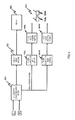
- FIG.1 is a block diagram showing a conventional stereoscopic display system, and a case will be described where 60-Hz left and right video signals are input.
- Left and right video signals of 60 Hz are input into stereoscopic video processing section 101 and converted into signals of 120 Hz cycle before being input into display drive section 102.
- display drive section 102 left and right video signals of 120 Hz are converted into a form that can be displayed by display 103 and input into display 103.
- left and right images are alternately displayed on display 103 in a 120 Hz cycle.
- left-side glass position control circuit 104L and right-side glass position control circuit 104R control left-side liquid crystal glass shutter 105L and right-side liquid crystal glass shutter 105R of stereoscopic observation glasses 105, respectively, based on the 120 Hz-cycle in stereoscopic video processing section 101.
- Glass position control circuits 104L and 104R control glass shutters 105L and 105R so that glass shutters 105L and 105R are opened and closed in synchronization with left and right alternate output images.
- Left and right images through glass shutters 105L and 105R are input into the left and right eyes of a person, respectively, to generate, as a result, a visual stereoscopic image in the head of the person.
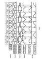
- FIG.2 is a control timing chart in a conventional stereoscopic display apparatus.
- display 103 is a CRT display.
- FIG.2A shows scanning timing of left and right video signals in display 103
- FIG.2B shows opening/closing timing of glass shutters 105L and 105R
- FIG.2C shows changes in luminous intensity of a fluorescent lamp near an apparatus over time
- FIG.2D shows luminous intensity of the fluorescent lamp passing through glass shutters 105L and 105R.
- the waveform of the luminous intensity of a fluorescent lamp has a full-wave rectification waveform.
- the waveform is repeated in a cycle of 100 Hz.
- Results of integration with components of the luminous intensity waveform of the fluorescent lamp of 100 Hz and the shutter opening/closing timing are the waveforms of light passing glass shutters 105L and 105R in FIG.2D .
- these waveforms have a cycle of 20 Hz.
- the frequency components of these waveforms are perceived by eyes as flicker, causing disturbance.
- this method adds right-side glass pulse width control circuit 141R and left-side glass pulse width control circuit 141L.
- the duration of an open period in which glasses are in an open state is basically coordinated with the fluorescent lamp cycle period (10 msec) of 100 Hz, by left-side glass pulse width control circuit 141L and right-side glass pulse width control circuit 141R.
- the duration of a closed period in which glasses are in a closed state is coordinated with the remaining time (6.7 msec) of the cycle period (16.7 msec) of the glasses of 60 Hz. Accordingly, the open period of glasses matches the cycle length of the luminous intensity waveform of a fluorescent lamp of 100 Hz, so that flicker does not occur.
- a stereoscopic display apparatus includes a display controller that causes a display section to display left-eye video and right-eye video based on an input left-eye video signal and right -eye video signal and a shutter control section that controls an open/closed state of left and right shutters of stereoscopic image observation glasses in an opening/closing cycle in accordance with a display cycle of the left-eye video and the right-eye video, wherein the shutter control section controls a duty ratio of an open period of each of the left and right shutters to a greater value than 50% and the display controller causes the display section to display video on a side whose shutter is in the open state of the left-eye video and the right-eye video only while the shutter control section exercises control so that one of the left and right shutters is in the closed state.
- a stereoscopic display apparatus includes a liquid crystal panel that modulates light entering from a rear side in accordance with an input left-eye video signal and right-eye video signal to display left-eye video and right-eye video, a backlight that radiates the liquid crystal panel with the light from the back side, a backlight control section that controls a light-emitting state of the backlight, and a shutter control section that controls an open/closed state of left and right shutters of stereoscopic image observation glasses in an opening/closing cycle in accordance with a display cycle of the left-eye video and the right-eye video, wherein the shutter control section controls a duty ratio of an open period of each of the left and right shutters to a greater value than 50% and the backlight control section exercises control so that the backlight is turned on only while the shutter control section exercises control so that one of the left and right shutters is in the closed state.
- a stereoscopic display apparatus includes a liquid crystal panel that modulates light entering from a rear side in accordance with an input left-eye video signal and right-eye video signal to display left-eye video and right-eye video, a backlight that radiates the liquid crystal panel with the light from the back side, a backlight control section that controls a light-emitting state of the backlight, a shutter control section that controls an open/closed state of left and right shutters of stereoscopic image observation glasses in an opening/closing cycle in accordance with a display cycle of the left-eye video and the right-eye video, and a flicker detection section that detects whether or not there is flicker due to interference of a brightness fluctuation cycle of ambient light of a local apparatus and the opening/closing cycle, wherein if the flicker is detected by the flicker detection section, the shutter control section controls a duty ratio of an open period of each of the left and right shutters to a greater value than 50% and if the flicker is
- a stereoscopic display apparatus includes a liquid crystal panel that modulates light entering from a rear side in accordance with an input left-eye video signal and right-eye video signal to display left-eye video and right-eye video, a backlight that radiates the liquid crystal panel with the light from the back side, a backlight control section that controls a light-emitting state of the backlight, and a shutter control section that controls an open/closed state of left and right shutters of stereoscopic image observation glasses in an opening/closing cycle in accordance with a display cycle of the left-eye video and the right-eye video, wherein an open period duration of each of the left and right shutters substantially matches a brightness fluctuation cycle of ambient light of a local apparatus and the backlight control section exercises control so that the backlight is turned on only while the shutter control section exercises control so that one of the left and right shutters is in the closed state.
- a stereoscopic display apparatus includes a liquid crystal panel that modulates light entering from a rear side in accordance with an input left-eye video signal and right-eye video signal to display left-eye video and right-eye video, a backlight that radiates the liquid crystal panel with the light from the back side, a backlight control section that controls a light-emitting state of the backlight, and a shutter control section that controls an open/closed state of left and right shutters of stereoscopic image observation glasses in an opening/closing cycle in accordance with a display cycle of the left-eye video and the right-eye video, wherein an open period duration of each of the left and right shutters substantially matches 1/2 of a cycle of a commercial power supply voltage supplied to a local apparatus and the backlight control section exercises control so that the backlight is turned on only while the shutter control section exercises control so that one of the left and right shutters is in the closed state.
- a stereoscopic display system includes the stereoscopic display apparatus and stereoscopic image observation glasses in which an open/closed state of left and right shutters is controlled by the stereoscopic display apparatus according to the left-eye video and the right-eye video.
- a stereoscopic display apparatus and a stereoscopic display system it is possible to provide a stereoscopic display apparatus and stereoscopic display system that are capable of reducing flicker due to the influence of a fluorescent lamp while preventing an increase in crosstalk.
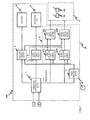
- FIG.4 is a block diagram showing the configuration of the stereoscopic display system according to Embodiment 1.
- Stereoscopic display system 100 includes stereoscopic display apparatus 10 and stereoscopic image observation glasses 5 in which an open/closed state of left and right shutters 5L and 5R is controlled by stereoscopic display apparatus 10 in accordance with the left-eye video and right-eye video.
- Stereoscopic display apparatus 10 includes stereoscopic video processing section 1, liquid crystal drive section 2, liquid crystal panel 31, backlight 32, shutter control section 4, and backlight control section 6.
- Stereoscopic video processing section 1 has left and right video signals having a basic vertical synchronous frequency input thereinto. Then, stereoscopic video processing section 1 divides left and right video signals into a left-eye video signal and a right-eye video signal using a frequency N times (N is a positive integer equal to 1 or greater) the basic vertical synchronous frequency and outputs the left-eye video signal and the right-eye video signal.
- N is a positive integer equal to 1 or greater
- the input left and right video signals (the left-eye video signal and the right-eye video signal) of 60 Hz are input, converted into signals of a 120 Hz cycle, and output to liquid crystal drive section 2, shutter control section 4, and backlight control section 6.
- Liquid crystal drive section 2 converts left and right video signals of 120 Hz into a form that can be displayed on liquid crystal panel 31. Liquid crystal drive section 2 inputs the left and right video signals into liquid crystal panel 31.
- Liquid crystal panel 31 modulates light entering from the rear side in accordance with the input left-eye video signal and right-eye video signal to display the left-eye video and the right-eye video in turn.
- Liquid crystal panel 31 of various drive methods such as the IPS (In Plane Switching) method, VA (Vertical Alignment) method, and TN (Twisted Nematic) method are applicable.
- Backlight 32 radiates liquid crystal panel 31 with light from the rear side.
- Backlight 32 to emit light by surface emission using a plurality of light-emitting diodes, arranged two-dimensionally, can be used.
- backlight 32 surface-emitting light by arranging a plurality of fluorescent tubes may also be used.
- Backlight 32 may also be of an edge type in which a light-emitting diode or a fluorescent tube is arranged at an edge thereof.
- Backlight 32 emits light based on a light emission control signal from backlight control section 6, based on the 120-Hz cycle output from stereoscopic video processing section 1.
- Shutter control section 4 controls the open/closed state of the left and right shutters of stereoscopic image observation glasses 5 in the opening/closing cycle in accordance with the display cycle of the left-eye video and right-eye video.
- shutter control section 4 controls the open/closed state in accordance with the display cycle of 120 Hz of the left-eye video and right-eye video and thus exercises control in the opening/closing cycle of 60 Hz.
- shutter control section 4 has left-side glass position control circuit 40L, right-side glass position control circuit 40R, left-side glass pulse width control circuit 41L, and right-side glass pulse width control circuit 41R.
- Left and right glass pulse width control circuits 41L and 41R decide the pulse duration of the open period of each of left and right shutters 5L and 5R based on the 120-Hz cycle in stereoscopic video processing section 1.
- Left and right glass position control circuits 40L and 40R have an output signal of glass pulse width control circuits 41L and 41R input thereinto, and decide the phase in the shutter open period. Then, the open/closed state of the left and right shutters 5L and 5R is controlled based on the output signal of glass position control circuits 40L and 40R.
- the pulse width (open period duration) of the shutter that makes flicker less likely is set by shutter control section 4 so that even a fluorescent lamp in a region where the commercial power supply frequency is 50 Hz does not flicker. If the input left and right video signals are 60 Hz and the full-wave rectified cycle of a fluorescent lamp is perfectly 100 Hz, the pulse width is set to 10 msec.
- backlight control section 6 decides the lighting period ("on" period) of the backlight based on the signal pulse width output by glass pulse width control circuits 41L and 41R and the type of backlight 32.
- Glass position control circuit 40L exercises control based on output of backlight control section 6 so that left-side shutter 5L is always in a closed period while backlight 32 is turned on in accordance with a right-eye video signal.
- Glass position control circuit 40R exercises control based on output of backlight control section 6 so that right-side shutter 5R is always in a closed period while backlight 32 is turned on corresponds to a left-eye video signal.
- FIG.5 shows a control timing chart of stereoscopic display system 100.
- FIG.5A shows scanning timing of left and right video signals in liquid crystal panel 31
- FIG.5B shows timing of light emission on/off control of backlight 32 by backlight control section 6 and a light emission period of backlight 32
- FIG.5C shows opening/closing timing of shutters 5L and 5R
- FIG.5D shows changes in luminous intensity of a fluorescent lamp near the apparatus over time
- FIG.5E shows the luminous intensity of the fluorescent lamp passing through shutters 5L and 5R.
- the power supply frequency is 50 Hz
- the luminous intensity of the fluorescent lamp has, as shown in FIG.5D , 100 Hz (10 msec) as the cycle of the waveform peak of luminous intensity.
- the duration of the open period of left and right shutters 5L and 5R of glasses is set to, as described above, 10 msec.
- left-eye shutter 5L is in a closed state while backlight 32 is turned on in accordance with a right-eye video signal
- right-eye shutter 5R is in a closed state while backlight 32 is turned on in accordance with a left-eye video signal.
- shutter control section 4 is configured to control the open/closed state of left and right shutters 5L and 5R so that the open period of each of left and right shutters 5L and 5R becomes 10 msec. That is, the open period duration of each of left and right shutters 5L and 5R substantially matches the cycle in which the brightness of ambient light fluctuates, in stereoscopic display apparatus 10.
- substantially matches means, for example, 90% of match or greater. By this means, it is possible to minimize flicker.
- the open period duration of each of left and right shutters 5L and 5R substantially matches 1/2 of the cycle of the commercial power supply voltage supplied to stereoscopic display apparatus 10.
- shutter control section 4 can provide a greater effect of reducing flicker than a conventional stereoscopic display apparatus by controlling the duty ratio of the open period for both left and right shutters 5L and 5R to a greater value than 50%. If the duty ratio of the open period for both left and right shutters 5L and 5R is greater than 50%, the open periods of shutters overlap.
- backlight control section exercises control such that backlight 32 is turned on only while shutter control section 4 exercises control so that one of left and right shutters 5L and 5R is in the closed state, which makes it possible to alleviate an occurrence of crosstalk.
- FIG.6 shows a control timing chart of stereoscopic display system 100 when a fluorescent tube is used as backlight 32.
- backlight control section 6 controls a light-emitting state of backlight 32 to prevent afterglow after backlight 32 is turned off from leaking while both shutters 5R and 5L are in the open state.
- Embodiment 2 of the present invention will be described with reference to the drawings.
- Embodiment 2 is mainly different from Embodiment 1 in that a flicker detection section to detect flicker is included.
- FIG.7 is a block diagram showing the configuration of stereoscopic display system 200 according to Embodiment 2.
- Stereoscopic display system 200 includes stereoscopic display apparatus 20 and stereoscopic image observation glasses 5 in which the open/closed state of left and right shutters 5L and 5R is controlled by stereoscopic display apparatus 20 in accordance with the left-eye video and right-eye video.
- Stereoscopic display apparatus 20 includes stereoscopic video processing section 1, liquid crystal drive section 2, liquid crystal panel 31, backlight 32, flicker detection section 7, shutter control section 8, and backlight control section 9.
- Flicker detection section 7 detects whether or not there is flicker due to interference of the brightness fluctuation cycle of ambient light of stereoscopic display apparatus 20 and the shutter opening/closing cycle. For example, if the amplitude of flicker is equal to a predetermined value or greater, it is determined that there is flicker, and, if the amplitude of flicker is the predetermined value or less, it is determined that there is not flicker.
- flicker detection section 7 has a synchronization signal of the frequency 120 Hz in left and right video signals and ambient light from a fluorescent lamp input thereinto to detect flicker of the fluorescent lamp in a region of the 50 Hz power supply frequency.
- shutter control section 8 controls the duty ratio of the open period for both left and right shutters 5L and 5R to a greater value than 50%. If flicker is not detected, shutter control section 8 controls the duty ratio of the open period of each of left and right shutters 5L and 5R to 50% or a lower value.
- backlight control section 9 exercises control such that the backlight is turned on only while shutter control section 8 exercises control so that one of left and right shutters 5L and 5R is in the closed state. In the present embodiment, if flicker is not detected by flicker detection section 7, backlight control section 9 exercises control so that backlight 32 is always turned on.
- FIG.8 shows a control timing chart of stereoscopic display system 200 when the power supply frequency is 60 Hz and flicker is not detected by flicker detection section 7.
- the pulse width of shutters 5R and 5L is adjusted to 1/120 sec or less (8.35 msec or less) and the on period of backlight 32 is adjusted so that the brightness can be maximized or crosstalk can be optimized.
- open periods of shutters 5L and 5R do not overlap so that crosstalk can be suppressed.
- the effect shown below can be obtained by switching control depending on whether or not flicker is detected. If flicker is detected, the shutter open period is increased to reduce flicker and also lighting timing of the backlight is controlled to prevent an occurrence of crosstalk. On the other hand, if flicker is not detected, an occurrence of crosstalk can be prevented by reducing the shutter open period and also brightness can be increased by causing the backlight to light at all times or responsiveness can be enhanced by raising the temperature of liquid crystal panel 31.
- backlight control section 8 exercises control so that backlight 32 is always turned on, but the present embodiment is not limited to this. If flicker is not detected by flicker detection section 7, backlight control section 9 exercises control such that the backlight is turned on only while shutter control section 8 exercises control so that one of left and right shutters 5L and 5R is in the open state. By this means, power consumption can be reduced.
- the method of detecting whether or not there is flicker is not limited to the above method.
- whether or not there is flicker may be determined such that it is determined that there is flicker when the power supply frequency of a stereoscopic display apparatus is 50 Hz or it is determined that there is not flicker when the power supply frequency is 60 Hz.
- Embodiment 3 of the present invention will be described with reference to the drawings.
- Embodiment 3 is different from Embodiments 1 and 2 in that flicker is further reduced when the full-wave rectified amplitude of light emission brightness of a fluorescent lamp is asymmetric.
- the configuration of the block diagram is almost the same as in Embodiment 2.
- flicker may not be sufficiently eliminated by Embodiment 1 or 2 if, for example, when the power supply frequency is 50 Hz, the full-wave rectified light emission of a fluorescent lamp does not have the 100 Hz cycle, but as a result of different frequencies in the first and second crests due to a rectifier circuit, the light emission has 50 Hz, or the basic frequency of input left and right video signals is slightly shifted from 60 Hz.
- the flicker detection section detects the cycle of flicker caused by interference of the brightness fluctuation cycle of ambient light of the local apparatus and the shutter opening/closing cycle. Then, the shutter control section controls the duration of the open period or the duration of the closed period of the left and right shutters based on the cycle of flicker.
- FIG.9 shows a control timing chart when brightness of the first crest and that of the second crest in a fluorescent lamp of the power supply frequency of 50 Hz are different
- FIG.9D shows luminous intensity of a fluorescent lamp.
- shutter control section 9 controls the open/closed state of left and right shutters 5L and 5R so that flicker becomes smaller. More specifically, flicker can further be improved by exercising control in accordance with the flicker cycle whose open period of shutters 5L and 5R is detected.
- the liquid crystal panel is an example of the display section.
- the backlight and backlight control section are examples of the display controller. If, for example, a stereoscopic display apparatus includes a display controller capable of controlling display timing of video to be displayed on a display section, an organic EL panel or a plasma display panel may be applied as the display section.
- the present invention is suitable as a stereoscopic display apparatus and a stereoscopic display system capable of reducing crosstalk and reducing flicker.
Landscapes
- Engineering & Computer Science (AREA)
- Multimedia (AREA)
- Signal Processing (AREA)
- Physics & Mathematics (AREA)
- General Physics & Mathematics (AREA)
- Optics & Photonics (AREA)
- Liquid Crystal Display Device Control (AREA)
- Testing, Inspecting, Measuring Of Stereoscopic Televisions And Televisions (AREA)
- Control Of Indicators Other Than Cathode Ray Tubes (AREA)
Applications Claiming Priority (2)
| Application Number | Priority Date | Filing Date | Title |
|---|---|---|---|
| JP2009251688 | 2009-11-02 | ||
| PCT/JP2010/006443 WO2011052236A1 (fr) | 2009-11-02 | 2010-11-01 | Appareil d'affichage tridimensionnel et système d'affichage tridimensionnel |
Publications (1)
| Publication Number | Publication Date |
|---|---|
| EP2498505A1 true EP2498505A1 (fr) | 2012-09-12 |
Family
ID=43921668
Family Applications (1)
| Application Number | Title | Priority Date | Filing Date |
|---|---|---|---|
| EP10826371A Withdrawn EP2498505A1 (fr) | 2009-11-02 | 2010-11-01 | Appareil d'affichage tridimensionnel et système d'affichage tridimensionnel |
Country Status (5)
| Country | Link |
|---|---|
| US (1) | US20110234777A1 (fr) |
| EP (1) | EP2498505A1 (fr) |
| JP (1) | JP5275461B2 (fr) |
| CN (1) | CN102227914A (fr) |
| WO (1) | WO2011052236A1 (fr) |
Families Citing this family (15)
| Publication number | Priority date | Publication date | Assignee | Title |
|---|---|---|---|---|
| JP5261533B2 (ja) * | 2010-09-14 | 2013-08-14 | パナソニック株式会社 | 情報表示装置、再生装置、および立体映像表示装置 |
| JP5661116B2 (ja) * | 2010-10-04 | 2015-01-28 | パナソニックIpマネジメント株式会社 | 映像表示装置 |
| WO2012081181A1 (fr) * | 2010-12-13 | 2012-06-21 | パナソニック株式会社 | Dispositif de lunettes et procédé de commande du dispositif de lunettes |
| US9426453B2 (en) * | 2011-03-04 | 2016-08-23 | Dolby Laboratories Licensing Corporation | Methods and apparatus for 3D shutter glasses synchronization |
| KR101906424B1 (ko) * | 2011-11-15 | 2018-12-10 | 엘지디스플레이 주식회사 | 이원 방식 홀로그래피 입체 영상 표시장치 |
| CN102547341A (zh) * | 2011-12-20 | 2012-07-04 | 四川长虹电器股份有限公司 | 一种调整电视机3d眼镜镜片开通时间的方法 |
| WO2013092198A1 (fr) * | 2011-12-20 | 2013-06-27 | Sony Corporation | Lecture de trame de télévision de manière synchrone comprenant un cycle de ligne |
| US9413982B2 (en) | 2012-02-28 | 2016-08-09 | Hewlett-Packard Development Company, L.P. | System and method for video frame sequence control |
| CN102663981A (zh) * | 2012-04-19 | 2012-09-12 | 深圳市华星光电技术有限公司 | 立体显示装置及其显示控制方法 |
| JP5950692B2 (ja) * | 2012-05-25 | 2016-07-13 | 三菱電機株式会社 | 立体画像表示装置 |
| WO2015097742A1 (fr) * | 2013-12-24 | 2015-07-02 | 株式会社 東芝 | Dispositif d'affichage vidéo en 3d |
| US9513507B2 (en) * | 2013-12-30 | 2016-12-06 | Shenzhen China Star Optoelectronics Technology Co., Ltd. | Three-dimensional liquid crystal display device, and shutter glass and control method for the same |
| US10459224B2 (en) * | 2014-09-29 | 2019-10-29 | Honeywell International Inc. | High transmittance eyewear for head-up displays |
| US9606355B2 (en) | 2014-09-29 | 2017-03-28 | Honeywell International Inc. | Apparatus and method for suppressing double images on a combiner head-up display |
| CN107272319A (zh) * | 2016-04-07 | 2017-10-20 | 中强光电股份有限公司 | 投影装置以及影像投影方法 |
Family Cites Families (20)
| Publication number | Priority date | Publication date | Assignee | Title |
|---|---|---|---|---|
| JPS62133891A (ja) | 1985-12-06 | 1987-06-17 | Victor Co Of Japan Ltd | 画像再生装置 |
| JPS6486694A (en) * | 1987-09-28 | 1989-03-31 | Sharp Kk | Stereoscopic video reproducing system |
| US5402191A (en) * | 1992-12-09 | 1995-03-28 | Imax Corporation | Method and apparatus for presenting stereoscopic images |
| JP3066298B2 (ja) | 1995-11-15 | 2000-07-17 | 三洋電機株式会社 | 立体画像観察用眼鏡の制御方法 |
| TW432354B (en) * | 1999-03-16 | 2001-05-01 | Asustek Comp Inc | The control device of LCD shutter glass |
| KR100381963B1 (ko) * | 2000-12-26 | 2003-04-26 | 삼성전자주식회사 | 감소된 플리커를 갖는 액정 표시 장치 및 그것의 플리커저감 방법 |
| TW548960B (en) * | 2001-01-23 | 2003-08-21 | Vrex Inc | Method and apparatus of flicker reduction for LC shutter glasses |
| JP4354449B2 (ja) * | 2005-10-26 | 2009-10-28 | オリンパス株式会社 | 表示画像撮像方法および装置 |
| US20100060723A1 (en) * | 2006-11-08 | 2010-03-11 | Nec Corporation | Display system |
| JP4438826B2 (ja) * | 2007-06-04 | 2010-03-24 | セイコーエプソン株式会社 | プロジェクタ及びプロジェクタ用光源装置の駆動方法 |
| CN101415126A (zh) * | 2007-10-18 | 2009-04-22 | 深圳Tcl新技术有限公司 | 一种产生三维图像效果的方法及数字视频装置 |
| CN101878654B (zh) * | 2007-11-28 | 2013-02-13 | 皇家飞利浦电子股份有限公司 | 立体可视化 |
| JP5111100B2 (ja) * | 2007-12-28 | 2012-12-26 | キヤノン株式会社 | 画像処理装置、画像処理方法、プログラム及び記憶媒体 |
| TWI383709B (zh) * | 2008-02-21 | 2013-01-21 | Chunghwa Picture Tubes Ltd | 光源驅動模組及電路 |
| JP4518283B2 (ja) * | 2008-03-19 | 2010-08-04 | セイコーエプソン株式会社 | 放電灯点灯装置及びその制御方法並びにプロジェクタ |
| JP2009251688A (ja) | 2008-04-01 | 2009-10-29 | Canon Inc | 構造化データ処理装置、方法及びプログラム |
| KR101362771B1 (ko) * | 2008-09-17 | 2014-02-14 | 삼성전자주식회사 | 입체 영상 표시 방법 및 장치 |
| JP2011053554A (ja) * | 2009-09-03 | 2011-03-17 | Toshiba Mobile Display Co Ltd | 有機el表示装置 |
| US20110090324A1 (en) * | 2009-10-15 | 2011-04-21 | Bit Cauldron Corporation | System and method of displaying three dimensional images using crystal sweep with freeze tag |
| JP5214020B2 (ja) * | 2009-12-07 | 2013-06-19 | パナソニック株式会社 | 立体表示システム |
-
2010
- 2010-11-01 EP EP10826371A patent/EP2498505A1/fr not_active Withdrawn
- 2010-11-01 CN CN2010800033433A patent/CN102227914A/zh active Pending
- 2010-11-01 WO PCT/JP2010/006443 patent/WO2011052236A1/fr not_active Ceased
- 2010-11-01 US US13/132,037 patent/US20110234777A1/en not_active Abandoned
- 2010-11-01 JP JP2011517129A patent/JP5275461B2/ja not_active Expired - Fee Related
Non-Patent Citations (1)
| Title |
|---|
| See references of WO2011052236A1 * |
Also Published As
| Publication number | Publication date |
|---|---|
| JP5275461B2 (ja) | 2013-08-28 |
| US20110234777A1 (en) | 2011-09-29 |
| JPWO2011052236A1 (ja) | 2013-03-14 |
| CN102227914A (zh) | 2011-10-26 |
| WO2011052236A1 (fr) | 2011-05-05 |
Similar Documents
| Publication | Publication Date | Title |
|---|---|---|
| EP2498505A1 (fr) | Appareil d'affichage tridimensionnel et système d'affichage tridimensionnel | |
| TWI428895B (zh) | 背光控制裝置及相關方法 | |
| RU2675047C2 (ru) | Блок фоновой подсветки, способ управления блоком фоновой подсветки и жидкокристаллический дисплей | |
| CN105489171B (zh) | 一种液晶显示装置及其背光控制方法 | |
| US8466869B2 (en) | Display apparatus that controls a length of an emission period or luminance of a display area according to temperature of a liquid crystal panel | |
| CN101369407A (zh) | 场序制彩色led背光源技术的控制方法 | |
| US20120188348A1 (en) | Video display device and video view system | |
| TW201117166A (en) | Image display apparatus and method | |
| US9509983B2 (en) | Image display viewing system and image display device | |
| WO2006006315A1 (fr) | Dispositif et méthode d'affichage, support d'enregistrement et programme | |
| JP5214020B2 (ja) | 立体表示システム | |
| US10578904B2 (en) | Field sequential type image display apparatus and image display method | |
| US20120069164A1 (en) | Image display device, image display system, image presenting method, and computer program | |
| TWI430251B (zh) | 色序法顯示器之色彩校正系統及其方法 | |
| US20110304709A1 (en) | Video display apparatus and video viewing system | |
| US8907885B2 (en) | Backlight control apparatus and associated method | |
| KR20120070196A (ko) | 액정 표시장치와 이의 구동방법 | |
| JP2006235461A (ja) | 液晶表示装置 | |
| KR102570515B1 (ko) | 타이밍 컨트롤러 및 이를 포함하는 표시장치 | |
| CN1981321A (zh) | 液晶显示装置及其光源的驱动方法 | |
| JP2012147142A (ja) | 立体映像表示システム及び立体映像表示方法並びに立体映像表示装置、照明装置 | |
| KR20120012877A (ko) | Led 광원의 구동 장치 | |
| JP2008065228A (ja) | 発光装置および液晶表示装置 | |
| TWI466088B (zh) | 顯示裝置 | |
| KR101811059B1 (ko) | 입체영상 표시장치 |
Legal Events
| Date | Code | Title | Description |
|---|---|---|---|
| PUAI | Public reference made under article 153(3) epc to a published international application that has entered the european phase |
Free format text: ORIGINAL CODE: 0009012 |
|
| 17P | Request for examination filed |
Effective date: 20120313 |
|
| AK | Designated contracting states |
Kind code of ref document: A1 Designated state(s): AL AT BE BG CH CY CZ DE DK EE ES FI FR GB GR HR HU IE IS IT LI LT LU LV MC MK MT NL NO PL PT RO RS SE SI SK SM TR |
|
| DAX | Request for extension of the european patent (deleted) | ||
| STAA | Information on the status of an ep patent application or granted ep patent |
Free format text: STATUS: THE APPLICATION HAS BEEN WITHDRAWN |
|
| 18W | Application withdrawn |
Effective date: 20140205 |