EP2500187A2 - Pneu à insert de paroi latérale thermoplastique - Google Patents
Pneu à insert de paroi latérale thermoplastique Download PDFInfo
- Publication number
- EP2500187A2 EP2500187A2 EP12159980A EP12159980A EP2500187A2 EP 2500187 A2 EP2500187 A2 EP 2500187A2 EP 12159980 A EP12159980 A EP 12159980A EP 12159980 A EP12159980 A EP 12159980A EP 2500187 A2 EP2500187 A2 EP 2500187A2
- Authority
- EP
- European Patent Office
- Prior art keywords
- tire
- insert
- thermoplastic
- ply
- sidewall
- Prior art date
- Legal status (The legal status is an assumption and is not a legal conclusion. Google has not performed a legal analysis and makes no representation as to the accuracy of the status listed.)
- Withdrawn
Links
- 229920001169 thermoplastic Polymers 0.000 title claims abstract description 46
- 239000004416 thermosoftening plastic Substances 0.000 title claims abstract description 45
- 238000004519 manufacturing process Methods 0.000 claims abstract description 4
- -1 polyethylene Polymers 0.000 claims description 15
- 239000000853 adhesive Substances 0.000 claims description 14
- 230000001070 adhesive effect Effects 0.000 claims description 14
- 238000000034 method Methods 0.000 claims description 13
- 239000004593 Epoxy Substances 0.000 claims description 4
- 239000004954 Polyphthalamide Substances 0.000 claims description 4
- 229920000728 polyester Polymers 0.000 claims description 4
- 229920001955 polyphenylene ether Polymers 0.000 claims description 4
- 229920006375 polyphtalamide Polymers 0.000 claims description 4
- 239000004952 Polyamide Substances 0.000 claims description 3
- 239000004698 Polyethylene Substances 0.000 claims description 3
- 239000004743 Polypropylene Substances 0.000 claims description 3
- 229920002647 polyamide Polymers 0.000 claims description 3
- 229920000573 polyethylene Polymers 0.000 claims description 3
- 229920001155 polypropylene Polymers 0.000 claims description 3
- 229920001971 elastomer Polymers 0.000 description 46
- 239000005060 rubber Substances 0.000 description 42
- 239000011324 bead Substances 0.000 description 30
- PPBRXRYQALVLMV-UHFFFAOYSA-N Styrene Chemical compound C=CC1=CC=CC=C1 PPBRXRYQALVLMV-UHFFFAOYSA-N 0.000 description 18
- 239000000203 mixture Substances 0.000 description 18
- KAKZBPTYRLMSJV-UHFFFAOYSA-N Butadiene Chemical compound C=CC=C KAKZBPTYRLMSJV-UHFFFAOYSA-N 0.000 description 16
- NINIDFKCEFEMDL-UHFFFAOYSA-N Sulfur Chemical compound [S] NINIDFKCEFEMDL-UHFFFAOYSA-N 0.000 description 15
- 239000011593 sulfur Substances 0.000 description 14
- 229910052717 sulfur Inorganic materials 0.000 description 14
- 239000000463 material Substances 0.000 description 12
- 150000003961 organosilicon compounds Chemical class 0.000 description 9
- 125000004432 carbon atom Chemical group C* 0.000 description 8
- 239000005062 Polybutadiene Substances 0.000 description 7
- 239000012815 thermoplastic material Substances 0.000 description 7
- NLHHRLWOUZZQLW-UHFFFAOYSA-N Acrylonitrile Chemical compound C=CC#N NLHHRLWOUZZQLW-UHFFFAOYSA-N 0.000 description 5
- 229920000297 Rayon Polymers 0.000 description 5
- 239000003795 chemical substances by application Substances 0.000 description 5
- 229920001577 copolymer Polymers 0.000 description 5
- 238000007720 emulsion polymerization reaction Methods 0.000 description 5
- 239000000945 filler Substances 0.000 description 5
- 238000002156 mixing Methods 0.000 description 5
- 229920002857 polybutadiene Polymers 0.000 description 5
- 239000002964 rayon Substances 0.000 description 5
- 238000004073 vulcanization Methods 0.000 description 5
- RRHGJUQNOFWUDK-UHFFFAOYSA-N Isoprene Chemical compound CC(=C)C=C RRHGJUQNOFWUDK-UHFFFAOYSA-N 0.000 description 4
- 239000004677 Nylon Substances 0.000 description 4
- XLOMVQKBTHCTTD-UHFFFAOYSA-N Zinc monoxide Chemical compound [Zn]=O XLOMVQKBTHCTTD-UHFFFAOYSA-N 0.000 description 4
- 239000000654 additive Substances 0.000 description 4
- 239000006229 carbon black Substances 0.000 description 4
- 235000019241 carbon black Nutrition 0.000 description 4
- 150000001875 compounds Chemical class 0.000 description 4
- 238000010276 construction Methods 0.000 description 4
- 239000000806 elastomer Substances 0.000 description 4
- 229920001778 nylon Polymers 0.000 description 4
- 239000003921 oil Substances 0.000 description 4
- 235000019198 oils Nutrition 0.000 description 4
- 229920000642 polymer Polymers 0.000 description 4
- 229920001897 terpolymer Polymers 0.000 description 4
- 230000000930 thermomechanical effect Effects 0.000 description 4
- VYPSYNLAJGMNEJ-UHFFFAOYSA-N Silicium dioxide Chemical compound O=[Si]=O VYPSYNLAJGMNEJ-UHFFFAOYSA-N 0.000 description 3
- 229910000831 Steel Inorganic materials 0.000 description 3
- 239000003963 antioxidant agent Substances 0.000 description 3
- MTAZNLWOLGHBHU-UHFFFAOYSA-N butadiene-styrene rubber Chemical compound C=CC=C.C=CC1=CC=CC=C1 MTAZNLWOLGHBHU-UHFFFAOYSA-N 0.000 description 3
- 229920003193 cis-1,4-polybutadiene polymer Polymers 0.000 description 3
- 150000001993 dienes Chemical class 0.000 description 3
- HQQADJVZYDDRJT-UHFFFAOYSA-N ethene;prop-1-ene Chemical group C=C.CC=C HQQADJVZYDDRJT-UHFFFAOYSA-N 0.000 description 3
- 238000010528 free radical solution polymerization reaction Methods 0.000 description 3
- 239000000446 fuel Substances 0.000 description 3
- 238000002844 melting Methods 0.000 description 3
- 230000008018 melting Effects 0.000 description 3
- 239000000178 monomer Substances 0.000 description 3
- 230000000704 physical effect Effects 0.000 description 3
- 230000003014 reinforcing effect Effects 0.000 description 3
- 229920005989 resin Polymers 0.000 description 3
- 239000011347 resin Substances 0.000 description 3
- 239000010959 steel Substances 0.000 description 3
- ZGHFDIIVVIFNPS-UHFFFAOYSA-N 3-Methyl-3-buten-2-one Chemical compound CC(=C)C(C)=O ZGHFDIIVVIFNPS-UHFFFAOYSA-N 0.000 description 2
- HGINCPLSRVDWNT-UHFFFAOYSA-N Acrolein Chemical compound C=CC=O HGINCPLSRVDWNT-UHFFFAOYSA-N 0.000 description 2
- OKTJSMMVPCPJKN-UHFFFAOYSA-N Carbon Chemical compound [C] OKTJSMMVPCPJKN-UHFFFAOYSA-N 0.000 description 2
- 239000004215 Carbon black (E152) Substances 0.000 description 2
- ZRALSGWEFCBTJO-UHFFFAOYSA-N Guanidine Chemical compound NC(N)=N ZRALSGWEFCBTJO-UHFFFAOYSA-N 0.000 description 2
- 229920002472 Starch Polymers 0.000 description 2
- 229920010741 Ultra High Molecular Weight Polyethylene (UHMWPE) Polymers 0.000 description 2
- 125000003545 alkoxy group Chemical group 0.000 description 2
- 239000004760 aramid Substances 0.000 description 2
- 229920003235 aromatic polyamide Polymers 0.000 description 2
- RTACIUYXLGWTAE-UHFFFAOYSA-N buta-1,3-diene;2-methylbuta-1,3-diene;styrene Chemical compound C=CC=C.CC(=C)C=C.C=CC1=CC=CC=C1 RTACIUYXLGWTAE-UHFFFAOYSA-N 0.000 description 2
- 229920005549 butyl rubber Polymers 0.000 description 2
- 229920003211 cis-1,4-polyisoprene Polymers 0.000 description 2
- 235000014113 dietary fatty acids Nutrition 0.000 description 2
- 239000012990 dithiocarbamate Substances 0.000 description 2
- 239000000839 emulsion Substances 0.000 description 2
- FJKIXWOMBXYWOQ-UHFFFAOYSA-N ethenoxyethane Chemical compound CCOC=C FJKIXWOMBXYWOQ-UHFFFAOYSA-N 0.000 description 2
- 239000000194 fatty acid Substances 0.000 description 2
- 229930195729 fatty acid Natural products 0.000 description 2
- 150000004665 fatty acids Chemical class 0.000 description 2
- 239000000499 gel Substances 0.000 description 2
- 238000010438 heat treatment Methods 0.000 description 2
- 229930195733 hydrocarbon Natural products 0.000 description 2
- 150000002430 hydrocarbons Chemical class 0.000 description 2
- 239000004615 ingredient Substances 0.000 description 2
- 229920001084 poly(chloroprene) Polymers 0.000 description 2
- 229920001707 polybutylene terephthalate Polymers 0.000 description 2
- 229920000139 polyethylene terephthalate Polymers 0.000 description 2
- 239000005020 polyethylene terephthalate Substances 0.000 description 2
- 229920001195 polyisoprene Polymers 0.000 description 2
- 230000002787 reinforcement Effects 0.000 description 2
- 238000010058 rubber compounding Methods 0.000 description 2
- 239000008107 starch Substances 0.000 description 2
- 235000019698 starch Nutrition 0.000 description 2
- 229920003051 synthetic elastomer Polymers 0.000 description 2
- 239000005061 synthetic rubber Substances 0.000 description 2
- 125000000391 vinyl group Chemical group [H]C([*])=C([H])[H] 0.000 description 2
- 239000001993 wax Substances 0.000 description 2
- 239000011787 zinc oxide Substances 0.000 description 2
- PMJHHCWVYXUKFD-SNAWJCMRSA-N (E)-1,3-pentadiene Chemical compound C\C=C\C=C PMJHHCWVYXUKFD-SNAWJCMRSA-N 0.000 description 1
- CBXRMKZFYQISIV-UHFFFAOYSA-N 1-n,1-n,1-n',1-n',2-n,2-n,2-n',2-n'-octamethylethene-1,1,2,2-tetramine Chemical compound CN(C)C(N(C)C)=C(N(C)C)N(C)C CBXRMKZFYQISIV-UHFFFAOYSA-N 0.000 description 1
- HECLRDQVFMWTQS-RGOKHQFPSA-N 1755-01-7 Chemical compound C1[C@H]2[C@@H]3CC=C[C@@H]3[C@@H]1C=C2 HECLRDQVFMWTQS-RGOKHQFPSA-N 0.000 description 1
- LLMLGZUZTFMXSA-UHFFFAOYSA-N 2,3,4,5,6-pentachlorobenzenethiol Chemical compound SC1=C(Cl)C(Cl)=C(Cl)C(Cl)=C1Cl LLMLGZUZTFMXSA-UHFFFAOYSA-N 0.000 description 1
- SDJHPPZKZZWAKF-UHFFFAOYSA-N 2,3-dimethylbuta-1,3-diene Chemical compound CC(=C)C(C)=C SDJHPPZKZZWAKF-UHFFFAOYSA-N 0.000 description 1
- OVSKIKFHRZPJSS-UHFFFAOYSA-N 2,4-D Chemical compound OC(=O)COC1=CC=C(Cl)C=C1Cl OVSKIKFHRZPJSS-UHFFFAOYSA-N 0.000 description 1
- SMZOUWXMTYCWNB-UHFFFAOYSA-N 2-(2-methoxy-5-methylphenyl)ethanamine Chemical compound COC1=CC=C(C)C=C1CCN SMZOUWXMTYCWNB-UHFFFAOYSA-N 0.000 description 1
- NIXOWILDQLNWCW-UHFFFAOYSA-N 2-Propenoic acid Natural products OC(=O)C=C NIXOWILDQLNWCW-UHFFFAOYSA-N 0.000 description 1
- 229910001369 Brass Inorganic materials 0.000 description 1
- 229920000049 Carbon (fiber) Polymers 0.000 description 1
- BWGNESOTFCXPMA-UHFFFAOYSA-N Dihydrogen disulfide Chemical compound SS BWGNESOTFCXPMA-UHFFFAOYSA-N 0.000 description 1
- 244000043261 Hevea brasiliensis Species 0.000 description 1
- VQTUBCCKSQIDNK-UHFFFAOYSA-N Isobutene Chemical group CC(C)=C VQTUBCCKSQIDNK-UHFFFAOYSA-N 0.000 description 1
- 241000254043 Melolonthinae Species 0.000 description 1
- CERQOIWHTDAKMF-UHFFFAOYSA-N Methacrylic acid Chemical compound CC(=C)C(O)=O CERQOIWHTDAKMF-UHFFFAOYSA-N 0.000 description 1
- VVQNEPGJFQJSBK-UHFFFAOYSA-N Methyl methacrylate Chemical compound COC(=O)C(C)=C VVQNEPGJFQJSBK-UHFFFAOYSA-N 0.000 description 1
- UTGQNNCQYDRXCH-UHFFFAOYSA-N N,N'-diphenyl-1,4-phenylenediamine Chemical compound C=1C=C(NC=2C=CC=CC=2)C=CC=1NC1=CC=CC=C1 UTGQNNCQYDRXCH-UHFFFAOYSA-N 0.000 description 1
- CHJJGSNFBQVOTG-UHFFFAOYSA-N N-methyl-guanidine Natural products CNC(N)=N CHJJGSNFBQVOTG-UHFFFAOYSA-N 0.000 description 1
- 239000006057 Non-nutritive feed additive Substances 0.000 description 1
- 229920002292 Nylon 6 Polymers 0.000 description 1
- 229920002302 Nylon 6,6 Polymers 0.000 description 1
- 229920005683 SIBR Polymers 0.000 description 1
- 229920000026 Si 363 Polymers 0.000 description 1
- XUIMIQQOPSSXEZ-UHFFFAOYSA-N Silicon Chemical compound [Si] XUIMIQQOPSSXEZ-UHFFFAOYSA-N 0.000 description 1
- 235000021355 Stearic acid Nutrition 0.000 description 1
- ATJFFYVFTNAWJD-UHFFFAOYSA-N Tin Chemical compound [Sn] ATJFFYVFTNAWJD-UHFFFAOYSA-N 0.000 description 1
- HCHKCACWOHOZIP-UHFFFAOYSA-N Zinc Chemical compound [Zn] HCHKCACWOHOZIP-UHFFFAOYSA-N 0.000 description 1
- 239000012190 activator Substances 0.000 description 1
- 230000000996 additive effect Effects 0.000 description 1
- 150000001299 aldehydes Chemical class 0.000 description 1
- 150000001336 alkenes Chemical class 0.000 description 1
- 125000005370 alkoxysilyl group Chemical group 0.000 description 1
- 125000000217 alkyl group Chemical group 0.000 description 1
- 150000001412 amines Chemical class 0.000 description 1
- 125000003118 aryl group Chemical group 0.000 description 1
- 238000005452 bending Methods 0.000 description 1
- 230000015572 biosynthetic process Effects 0.000 description 1
- 239000010951 brass Substances 0.000 description 1
- 229920005557 bromobutyl Polymers 0.000 description 1
- WFYPICNXBKQZGB-UHFFFAOYSA-N butenyne Chemical group C=CC#C WFYPICNXBKQZGB-UHFFFAOYSA-N 0.000 description 1
- DKVNPHBNOWQYFE-UHFFFAOYSA-N carbamodithioic acid Chemical compound NC(S)=S DKVNPHBNOWQYFE-UHFFFAOYSA-N 0.000 description 1
- 239000004917 carbon fiber Substances 0.000 description 1
- 229920005556 chlorobutyl Polymers 0.000 description 1
- 239000002131 composite material Substances 0.000 description 1
- 239000000470 constituent Substances 0.000 description 1
- 125000000000 cycloalkoxy group Chemical group 0.000 description 1
- 125000000113 cyclohexyl group Chemical group [H]C1([H])C([H])([H])C([H])([H])C([H])(*)C([H])([H])C1([H])[H] 0.000 description 1
- 230000003247 decreasing effect Effects 0.000 description 1
- 230000003111 delayed effect Effects 0.000 description 1
- 230000001419 dependent effect Effects 0.000 description 1
- CJSBUWDGPXGFGA-UHFFFAOYSA-N dimethyl-butadiene Natural products CC(C)=CC=C CJSBUWDGPXGFGA-UHFFFAOYSA-N 0.000 description 1
- SWSQBOPZIKWTGO-UHFFFAOYSA-N dimethylaminoamidine Natural products CN(C)C(N)=N SWSQBOPZIKWTGO-UHFFFAOYSA-N 0.000 description 1
- 150000002019 disulfides Chemical class 0.000 description 1
- 150000004659 dithiocarbamates Chemical class 0.000 description 1
- 239000013536 elastomeric material Substances 0.000 description 1
- 150000002170 ethers Chemical class 0.000 description 1
- 125000002534 ethynyl group Chemical class [H]C#C* 0.000 description 1
- 239000011152 fibreglass Substances 0.000 description 1
- 150000002357 guanidines Chemical class 0.000 description 1
- 229920005555 halobutyl Polymers 0.000 description 1
- 125000004968 halobutyl group Chemical group 0.000 description 1
- 150000002576 ketones Chemical class 0.000 description 1
- 239000004816 latex Substances 0.000 description 1
- 229920000126 latex Polymers 0.000 description 1
- 239000002184 metal Substances 0.000 description 1
- 229910052751 metal Inorganic materials 0.000 description 1
- VNWKTOKETHGBQD-UHFFFAOYSA-N methane Chemical compound C VNWKTOKETHGBQD-UHFFFAOYSA-N 0.000 description 1
- 239000004200 microcrystalline wax Substances 0.000 description 1
- 235000019808 microcrystalline wax Nutrition 0.000 description 1
- 229920003052 natural elastomer Polymers 0.000 description 1
- 229920001194 natural rubber Polymers 0.000 description 1
- QIQXTHQIDYTFRH-UHFFFAOYSA-N octadecanoic acid Chemical compound CCCCCCCCCCCCCCCCCC(O)=O QIQXTHQIDYTFRH-UHFFFAOYSA-N 0.000 description 1
- OQCDKBAXFALNLD-UHFFFAOYSA-N octadecanoic acid Natural products CCCCCCCC(C)CCCCCCCCC(O)=O OQCDKBAXFALNLD-UHFFFAOYSA-N 0.000 description 1
- JRZJOMJEPLMPRA-UHFFFAOYSA-N olefin Natural products CCCCCCCC=C JRZJOMJEPLMPRA-UHFFFAOYSA-N 0.000 description 1
- PMJHHCWVYXUKFD-UHFFFAOYSA-N penta-1,3-diene Chemical compound CC=CC=C PMJHHCWVYXUKFD-UHFFFAOYSA-N 0.000 description 1
- 125000001997 phenyl group Chemical group [H]C1=C([H])C([H])=C(*)C([H])=C1[H] 0.000 description 1
- 230000036314 physical performance Effects 0.000 description 1
- 239000000049 pigment Substances 0.000 description 1
- 239000004014 plasticizer Substances 0.000 description 1
- 230000000379 polymerizing effect Effects 0.000 description 1
- 229920000098 polyolefin Polymers 0.000 description 1
- 229920001296 polysiloxane Polymers 0.000 description 1
- 239000005077 polysulfide Substances 0.000 description 1
- 229920001021 polysulfide Polymers 0.000 description 1
- 150000008117 polysulfides Polymers 0.000 description 1
- 239000010734 process oil Substances 0.000 description 1
- 238000010074 rubber mixing Methods 0.000 description 1
- JPPLPDOXWBVPCW-UHFFFAOYSA-N s-(3-triethoxysilylpropyl) octanethioate Chemical compound CCCCCCCC(=O)SCCC[Si](OCC)(OCC)OCC JPPLPDOXWBVPCW-UHFFFAOYSA-N 0.000 description 1
- 229910052710 silicon Inorganic materials 0.000 description 1
- 239000010703 silicon Substances 0.000 description 1
- 239000000377 silicon dioxide Substances 0.000 description 1
- 125000006850 spacer group Chemical group 0.000 description 1
- 239000008117 stearic acid Substances 0.000 description 1
- QAZLUNIWYYOJPC-UHFFFAOYSA-M sulfenamide Chemical group [Cl-].COC1=C(C)C=[N+]2C3=NC4=CC=C(OC)C=C4N3SCC2=C1C QAZLUNIWYYOJPC-UHFFFAOYSA-M 0.000 description 1
- 229920001059 synthetic polymer Polymers 0.000 description 1
- 239000004753 textile Substances 0.000 description 1
- 150000003557 thiazoles Chemical class 0.000 description 1
- 150000003568 thioethers Chemical class 0.000 description 1
- 150000003585 thioureas Chemical class 0.000 description 1
- 229960002447 thiram Drugs 0.000 description 1
- VTHOKNTVYKTUPI-UHFFFAOYSA-N triethoxy-[3-(3-triethoxysilylpropyltetrasulfanyl)propyl]silane Chemical compound CCO[Si](OCC)(OCC)CCCSSSSCCC[Si](OCC)(OCC)OCC VTHOKNTVYKTUPI-UHFFFAOYSA-N 0.000 description 1
- 235000015112 vegetable and seed oil Nutrition 0.000 description 1
- 239000008158 vegetable oil Substances 0.000 description 1
- 229920001567 vinyl ester resin Polymers 0.000 description 1
- 239000012991 xanthate Substances 0.000 description 1
- 229910052725 zinc Inorganic materials 0.000 description 1
- 239000011701 zinc Substances 0.000 description 1
Images

Classifications
-
- B—PERFORMING OPERATIONS; TRANSPORTING
- B60—VEHICLES IN GENERAL
- B60C—VEHICLE TYRES; TYRE INFLATION; TYRE CHANGING; CONNECTING VALVES TO INFLATABLE ELASTIC BODIES IN GENERAL; DEVICES OR ARRANGEMENTS RELATED TO TYRES
- B60C9/00—Reinforcements or ply arrangement of pneumatic tyres
- B60C9/02—Carcasses
- B60C9/14—Carcasses built-up with sheets, webs, or films of homogeneous material, e.g. synthetics, sheet metal, rubber
-
- B—PERFORMING OPERATIONS; TRANSPORTING
- B60—VEHICLES IN GENERAL
- B60C—VEHICLE TYRES; TYRE INFLATION; TYRE CHANGING; CONNECTING VALVES TO INFLATABLE ELASTIC BODIES IN GENERAL; DEVICES OR ARRANGEMENTS RELATED TO TYRES
- B60C17/00—Tyres characterised by means enabling restricted operation in damaged or deflated condition; Accessories therefor
- B60C17/0009—Tyres characterised by means enabling restricted operation in damaged or deflated condition; Accessories therefor comprising sidewall rubber inserts, e.g. crescent shaped inserts
- B60C17/0018—Tyres characterised by means enabling restricted operation in damaged or deflated condition; Accessories therefor comprising sidewall rubber inserts, e.g. crescent shaped inserts two or more inserts in each sidewall portion
Definitions
- the present invention is directed to a pneumatic tire in accordance with claim 1 and to a method in accordance with claim 9.
- the tire is a runflat tire.
- a pneumatic tire preferably a runflat tire, comprising a sidewall insert, the sidewall insert comprising an axially layered thermoplastic.
- Tires containing the thermoplastic inserts of this invention comprise a toroidally-shaped carcass and an outer, circumferential tread designed to be ground-contacting, wherein said carcass comprises two spaced-apart inextensible bead portions, two spaced-apart sidewalls each individually extending radially inward from and connecting said tread to said bead portions and preferably at least one cord reinforced ply extending from bead to bead and through the sidewalls.
- a substantially crescent-shaped rubber insert is juxtapositioned to and axially inward of at least one of said carcass plies in one or each of said sidewalls of the tire.
- the runflat tire with a thermoplastic insert is lighter than prior art runflat tires with conventional inserts made of compounded rubber.
- Such rubber inserts have a high carbon black content to ensure a sufficient stiffness to support a tire during a deflation episode.
- a runflat tire with a thermoplastic insert has sufficient stiffness, but at lower overall tire weight.
- the insert has a maximum thickness at a location about midway between the bead portions and the tread in the sidewall region of the tire.
- a significant function of the insert in the sidewall portion of the tire is to stiffen/support the sidewall structure when the tire is operated without inflation pressure.
- the shape of the insert is described as preferably being substantially crescent in shape. This is intended to also include an entrunkated crescent shape, particularly where the entrunkated portion of the crescent-shaped insert is juxtapositioned to the tire's bead portion.
- said tire carcass may have from one to three plies comprising a first axially inner ply and optionally one or two additional plies as a second ply and third ply, respectively.
- Each additional ply is positioned sequentially axially outward from said first ply in the sidewall region of the tire.
- said tire contains one ply in its carcass wherein said insert is juxtapositioned to and axially inward of said ply in the sidewall region of the tire.
- said tire contains, in its carcass, an axially inner first ply and a second ply axially outward from the first ply; wherein said insert is juxtapositioned to and axially inward of said first ply, in the sidewall region of the tire.
- said tire contains, in its carcass, an axially inner first ply and an axially outer second ply; wherein said insert is juxtapositioned to and interposed between said first and second ply, in the sidewall region of the tire.
- said tire contains, in its carcass, an axially inner first ply and an axially outer second ply; wherein one of said inserts is juxtapositioned to and interposed between said first and second ply, in the sidewall region of the tire, and another of said inserts is juxtapositioned to and axially inward of said first ply, in the sidewall region of the tire.
- said tire contains, in its carcass, an axially inner first ply, a second ply axially outward from said first ply and a third ply axially outward from said second ply; wherein said insert is juxtapositioned to and axially inward of said first ply, in the sidewall region of the tire.
- said tire contains, in its carcass, an axially inner first ply, a second ply axially outward from said first ply and a third ply axially outward from said second ply; wherein said insert is juxtapositioned to and interposed between (a) said first and second plies and/or (b) said second and third plies, in the sidewall region of the tire.
- said tire contains, in its carcass, an axially inner first ply, a second ply axially outward from said first ply and a third ply axially outward from said second ply; wherein said insert is juxtapositioned to and interposed between (a) said first and second plies and/or (b) said second and third plies, in the sidewall region of the tire and, also, an insert juxtapositioned to and axially inward of the innermost of said plies.
- the innermost ply, or plies has synthetic or textile cord reinforcement of polyester, nylon, rayon or aramid, preferably nylon; while the outermost ply preferably has aramid, rayon, carbon fiber, fiberglass or metal cord reinforcement, preferably brass and/or zinc-coated steel cords.
- the first ply has reinforcing cords of rayon and the second and additional plies are cords of rayon.
- the outermost ply preferably has cords of a higher modulus (i.e., steel cords) and the innermost ply, or plies, have cords of a lower modulus (i.e., nylon or rayon).
- a higher modulus i.e., steel cords
- the innermost ply, or plies have cords of a lower modulus (i.e., nylon or rayon).
- At least one ply preferably the innermost ply, extends from bead core to bead cord and wraps around the bead core.
- FIG.-1 shows the fragmentary cross-section of a runflat tire 1, its tread 2, bead portion 3, sidewall or sidewall region 4, inextensible wire bead core 5, rubber chafer 6, rubber toeguard 7, rubber composition innerliner 8, belt structure 9 underlying a portion of the tread 2, carcass ply 10, carcass ply turnup 11, thermoplastic insert 12 and apex 13.
- Thermoplastic insert 12 comprises axially-layered thermoplastic layers 22, as will be discussed in more detail.
- a similar construction is used on the section of the tire opposite the radial centerline of the tire (not shown). The tire axial direction is indicated by an arrow.
- the cords for use in the carcass plies may comprise from one (monofilament) to multiple twisted filaments.
- the number of total filaments in the cord may range from 1 to 13.
- the cords, particularly metallic cords, of the carcass ply are generally oriented such that the tire according to the present invention is what is commonly referred to as a radial.
- the cords of the carcass ply intersect the equatorial plane (EP) of the tire at an angle in the range of from 75 ° to 105°.
- the cords intersect at an angle of from 82 ° to 98°.
- a more preferred range is from 89 °to 91 °.
- the first and second reinforcing ply structure each may comprise a single ply layer; however, any number of carcass plies may be used.
- the first ply structure has a pair of turnup ends respectively which wrap about each bead core 5 of the bead portion 3 of the carcass.
- the ends 11 of ply 10 are in proximity to the bead core 5 and terminate radially adjacent on either side of the bead core 5, above the bead core 5 or can be wrapped around the bead core 5 and terminates radially below the turnup end 11 of ply 10 as shown.
- the turnup ends 11 of ply 10 wrap about the second ply ends and the bead core 5.
- the turnup ends of the first ply 11 terminates radially a distance above the nominal rim diameter of the tire 1 in proximity to the radial location of the maximum section width of the tire.
- the turnup ends are located within 20 percent of the section height of the tire from the radial location of the maximum section width, most preferably terminating at the radial location of the maximum section width.
- the bead core 5 is preferably constructed of a single or monofilament steel wire continuously wrapped. Located within the bead region 3 and the radially inner portions of the sidewall portions 4 are high modulus elastomeric apex inserts disposed between ply 10 and the turnup ends 11, respectively. The apex 13 extends from the radially outer portion of bead portions respectively, up into the sidewall portion gradually decreasing in cross-sectional width. The apex 13 terminates at a radially outer end.
- the insert 12 may extend from each bead region radially to the edge of the tread, usually to just beneath the reinforcing belt structures 9. As illustrated in FIG.-1, the sidewall portions include a thermoplastic insert 12. Additional inserts (not shown) may be included between additional plies (not shown).
- the inserts 12 each have a thickness at its maximum thickness of at least three percent of the maximum section height "SH" at a location approximately radially aligned to the maximum section width of the tire.
- the overall cross-sectional thickness of the combination of elastomeric inserts preceding from the bead portions to the radial location of the maximum section width (SW) is preferably of constant thickness.
- the overall sidewall and carcass thickness is preferably at least 11.5 mm at the maximum section width location and increases to an overall thickness in the region where it merges into the shoulder near the lateral tread edges.
- the overall thickness of the sidewall in the shoulder region of the tire is at least one hundred percent (100%) of the overall sidewall thickness at the maximum section width (SW). This ratio means that the sidewall can be made substantially thinner than the predecessor-type runflat tires.
- the tire of the present invention has at least one ply having a turnup end 11 (wrapped around the bead core 5) while another ply can simply be terminated adjacent to the bead core 5 without actually wrapping around the bead core 5.
- the insert 12 is made of thermoplastic material.
- the insert 12 is designed to prevent the tire's sidewall from collapsing when operating under no inflation pressure.
- the material shape and cross-sectional profile is modified to insure the ride performance and sidewall spring rate is acceptable.
- the cross-sectional area of the insert can be reduced without compromising performance characteristics by utilizing stiffer materials in the insert. Thus, weight can be reduced by using stiffer thermoplastic materials in the insert.
- the second insert and third insert can be of the same or different material physical properties relative to the first insert 12. This means that the combination of a hard second insert, and/or third insert, if used, with a softer first insert 12 is contemplated as well as the combination of a hard first insert 12 with a softer second and/or third insert.
- the second insert and third insert, if used, are made of thermoplastic or elastomeric material. These inserts can be used in multiples of inserts interposed between adjacent plies when more than two plies are used in the carcass structure.
- the second and third inserts when used, act as a spacer between the adjacent plies.
- the cords of the plies particularly the radially outer ply is placed in tension when the tire is operated uninflated.
- compositions for the inserts utilized in this invention for the aforesaid pneumatic tire construction are preferably characterized by physical properties which enhance their utilization in the invention which are, collectively, believed to be a departure from properties of conventional rubber compositions normally used in pneumatic tire sidewalls, particularly the combination of inserts 12 and with plies 10 having a combination of either dissimilar or similar high stiffness yet essentially low hysteresis properties.
- the aforesaid inserts 12 are designed to have a high degree of stiffness yet also having lower weight than for an inserts not containing the thermoplastic.
- thermoplastic inserts are constructed from multiple, relatively thin layers of thermoplastic material.
- the thermoplastic layers each have a thickness in a range of 0.1 to 1 mm.
- the multiple layers of thermoplastic are layered sequentially in such a way as to form the desired cross-sectional thicknesses and shape suitable for used as a runflat insert.
- the multiple layers of thermoplastic may be layered using manual or automatic (continuous) methods.
- the thermoplastic insert is constructed using a method as illustrated in FIG. - 2.
- innerliner material 26 (corresponding to the innerliner 8 in FIG. - 1) has been built onto tire drum 30.
- Thermoplastic material in the form of a continuous tape is transferred onto surface 28 of innerliner material 26 by unwinding from spool 20 in the direction of arrow 32.
- Tape 22 is layered to form partially built insert 24 by sequential application of tape 22 during rotation of tire drum 30 and spool 20.
- Insert regions 36A,B are indicated by the areas between the dashed lines 37A and 37B, respectively.
- Tape 22 is disposed in regions 36A,B of surface 28; regions 36 correspond to the desired location of the inserts 12 (FIG. - 1).
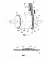
- a partially built insert 24 is shown in cross-section in FIG. - 3, with a plurality of layers of tape 22 disposed on surface 28 of innerliner material 26 after sequential rotations of tire drum 30.
- the arrow indicates the tire axial direction.
- the various layers of tape 22 are stacked and overlapped in such a manner as to form the desired cross-sectional thicknesses and shape of the partially built insert 24.
- the relative overlap of sequential layers of tape 22 may be controlled by indexing spool 20 along its axle 34.
- tape 22 is cut from spool 20.
- the remaining tire components (sidewall, beads, tread, etc., not shown) are built onto the tire building drum 30 in the conventional manner.
- the layers of tape 22 are seen to be axially-layered with respect to the axial direction of the tire 1.
- the layers of tape 22 are fused by application of heat during cure of tire 1 to form insert 12, or by action of an adhesive applied to tape 22.
- insert 12 from thermoplastic tape layers 22 facilitates use of a thermoplastic insert in a runflat tire.
- Construction of a thermoplastic insert from a monolithic, preshaped thermoplastic insert material is difficult due to the high modulus of the material. Bending such a monolithic material for use during tire building requires thermal softening of the thermoplastic, which adds a level of complexity in processing and operator handling due to the high temperature.
- the relatively thin tape 22 allows easy handling and application of the thermoplastic during tire building without need for thermal softening.
- the insert 12 comprises a plurality of axially layered thermoplastic layers. In one embodiment, the insert comprises at least 10 axially layered thermoplastic layers.
- Suitable thermoplastic materials for use as the tape 22 and insert 12 include polyolefin such as polyethylene and polypropylene; polyamides such as nylon 6, nylon 6,6; nylon 6,12; polyesters such as polyethylene terephthalate (PET) and polybutylene terephthalate (PBT); polyphenylene ether (PPE); and polyphthalamide (PPA).
- Suitable thermoplastics preferably have a melting temperature greater than the temperatures experienced during a runflat event by the tire. In one embodiment, the thermoplastic has a melting temperature greater than 160°C. In one embodiment, the thermoplastic has a melting temperature greater than 130°C.
- the thermoplastic material may be treated on its surface with an adhesive to promote adhesion between the layers of tape 22 and the adhesion between the tape 22 and adjacent rubber components of the tire.
- the tape 22 is dipped in an RFL (resorcinol-formaldehyde-latex) type adhesive as is known in the rubber compounding art.
- the tape 22 is dipped in an epoxy-based adhesive.
- the tape 22 is dipped in a combination of RFL and epoxy-based adhesives. The adhesive, if used, is then disposed between the layers of tape 22 in the insert 12.
- the tire components other than the thermoplastic insert may be made from rubber compositions with rubbers or elastomers containing olefinic unsaturation.
- rubber or elastomer containing olefinic unsaturation is intended to include both natural rubber and its various raw and reclaim forms as well as various synthetic rubbers.
- the terms “rubber” and “elastomer” may be used interchangeably, unless otherwise prescribed.
- the terms “rubber composition,” “compounded rubber” and “rubber compound” are used interchangeably to refer to rubber which has been blended or mixed with various ingredients and materials.
- Representative synthetic polymers are the homopolymerization products of butadiene and its homologues and derivatives, for example, methylbutadiene, dimethylbutadiene and pentadiene as well as copolymers such as those formed from butadiene or its homologues or derivatives with other unsaturated monomers.
- acetylenes for example, vinyl acetylene
- olefins for example, isobutylene, which copolymerizes with isoprene to form butyl rubber
- vinyl compounds for example, acrylic acid, acrylonitrile (which polymerize with butadiene to form NBR), methacrylic acid and styrene, the latter compound polymerizing with butadiene to form SBR, as well as vinyl esters and various unsaturated aldehydes, ketones and ethers, e.g., acrolein, methyl isopropenyl ketone and vinylethyl ether.
- synthetic rubbers include neoprene (polychloroprene), polybutadiene (including cis-1,4-polybutadiene), polyisoprene (including cis-1,4-polyisoprene), butyl rubber, halobutyl rubber such as chlorobutyl rubber or bromobutyl rubber, styrene/isoprene/butadiene rubber, copolymers of 1,3-butadiene or isoprene with monomers such as styrene, acrylonitrile and methyl methacrylate, as well as ethylene/propylene terpolymers, also known as ethylene/propylene/diene monomer (EPDM), and in particular, ethylene/propylene/ dicyclopentadiene terpolymers.
- neoprene polychloroprene
- polybutadiene including cis-1,4-polybutadiene
- Rubbers which may be used include alkoxy-silyl end functionalized solution polymerized polymers (SBR, PBR, IBR and SIBR), silicon-coupled and tin-coupled star-branched polymers.
- SBR alkoxy-silyl end functionalized solution polymerized polymers
- PBR polybutadiene
- IBR IBR
- SIBR silicon-coupled star-branched polymers.
- the preferred rubber or elastomers are polybutadiene and SBR.
- the rubber is preferably of at least two of diene based rubbers.
- a combination of two or more rubbers is preferred such as cis 1,4-polyisoprene rubber (natural or synthetic, although natural is preferred), 3,4-polyisoprene rubber, styrene/isoprene/butadiene rubber, emulsion and solution polymerization derived styrene/butadiene rubbers, cis 1,4-polybutadiene rubbers and emulsion polymerization prepared butadiene/acrylonitrile copolymers.
- an emulsion polymerization derived styrene/butadiene might be used having a relatively conventional styrene content of about 20 to about 28 percent bound styrene or, for some applications, an E-SBR having a medium to relatively high bound styrene content, namely, a bound styrene content of about 30 to about 45 percent.
- E-SBR emulsion polymerization prepared E-SBR
- styrene and 1,3-butadiene are copolymerized as an aqueous emulsion.
- the bound styrene content can vary, for example, from 5 to 50 percent.
- the E-SBR may also contain acrylonitrile to form a terpolymer rubber, as E-SBAR, in amounts, for example, of 2 to 30 weight percent bound acrylonitrile in the terpolymer.
- Emulsion polymerization prepared styrene/butadiene/acrylonitrile copolymer rubbers containing 2 to 40 weight percent bound acrylonitrile in the copolymer are also contemplated as diene based rubbers for use in this invention.
- the solution polymerization prepared SBR typically has a bound styrene content in a range of 5 to 50, preferably 9 to 36 percent.
- cis 1,4-polybutadiene rubber may be used.
- BR cis 1,4-polybutadiene rubber
- Such BR can be prepared, for example, by organic solution polymerization of 1,3-butadiene.
- the BR may be conveniently characterized, for example, by having at least a 90 percent cis 1,4-content.
- the rubber composition may also include up to 70 phr of processing oil.
- Suitable process oils include aromatic, paraffinic, napthenic, vegetable oils, and low PCA oils, such as MES, TDAE, SRAE and heavy naphthenic oils.
- the vulcanizable rubber composition may include from 10 to 150 phr of silica.
- silicas such as, only for example herein silicas commercially available from PPG Industries under the Hi-Sil trademark with designations 210 and 243; silicas available from Rhodia, with, for example, designations of Z1165MP and Z165GR and silicas available from Degussa AG with, for example, designations VN2 and VN3.
- the vulcanizable rubber composition may include from 1 to 100 phr of carbon black, crosslinked particulate polymer gel, ultra high molecular weight polyethylene (UHMWPE) or plasticized starch.
- UHMWPE ultra high molecular weight polyethylene
- carbon blacks can be used as a conventional filler.
- Representative examples of such carbon blacks include N110, N121, N134, N220, N231, N234, N242, N293, N299, N315, N326, N330, N332, N339, N343, N347, N351, N358, N375, N539, N550, N582, N630, N642, N650, N683, N754, N762, N765, N774, N787, N907, N908, N990 and N991.
- fillers may be used in the rubber composition including, but not limited to, particulate fillers including ultra high molecular weight polyethylene (UHMWPE), particulate polymer gels and plasticized starch composite filler.
- UHMWPE ultra high molecular weight polyethylene
- particulate polymer gels and plasticized starch composite filler.
- the rubber composition for use in the tire tread may contain a conventional sulfur containing organosilicon compound.
- suitable sulfur containing organosilicon compounds are of the formula: Z-Alk-S n -Alk-Z II in which Z is selected from the group consisting of where R 1 is an alkyl group of 1 to 4 carbon atoms, cyclohexyl or phenyl; R 2 is alkoxy of 1 to 8 carbon atoms, or cycloalkoxy of 5 to 8 carbon atoms; Alk is a divalent hydrocarbon of 1 to 18 carbon atoms and n is an integer of 2 to 8.
- the sulfur containing organosilicon compounds are the 3,3'-bis(trimethoxy or triethoxy silylpropyl) sulfides. In one embodiment, the sulfur containing organosilicon compounds are 3,3'-bis(triethoxysilylpropyl) disulfide and 3,3'-bis(triethoxysilylpropyl) tetrasulfide. Therefore, as to formula II, Z may be where R 2 is an alkoxy of 2 to 4 carbon atoms, alternatively 2 carbon atoms; alk is a divalent hydrocarbon of 2 to 4 carbon atoms, alternatively with 3 carbon atoms; and n is an integer of from 2 to 5, alternatively 2 or 4.
- suitable sulfur containing organosilicon compounds include compounds disclosed in US-B- 6,608,125 .
- suitable sulfur containing organosilicon compounds include those disclosed in US-A- 2003/0130535 .
- the sulfur containing organosilicon compound is Si-363 from Degussa.
- the amount of the sulfur containing organosilicon compound in a rubber composition will vary depending on the level of other additives that are used. Generally speaking, the amount of the compound will range from 0.5 to 20 phr.
- the rubber composition would be compounded by methods generally known in the rubber compounding art, such as mixing the various sulfur-vulcanizable constituent rubbers with various commonly used additive materials such as, for example, sulfur donors, curing aids, such as activators and retarders and processing additives, such as oils, resins including tackifying resins and plasticizers, fillers, pigments, fatty acid, zinc oxide, waxes, antioxidants and antiozonants and peptizing agents.
- additives mentioned above are selected and commonly used in conventional amounts.
- sulfur donors include elemental sulfur (free sulfur), an amine disulfide, polymeric polysulfide and sulfur olefin adducts.
- the sulfur-vulcanizing agent is elemental sulfur.
- the sulfur-vulcanizing agent may be used in an amount ranging from 0.5 to 8 phr.
- Typical amounts of tackifier resins, if used, comprise about 0.5 to about 10 phr.
- Typical amounts of processing aids comprise 1 to 50 phr.
- Typical amounts of antioxidants comprise 1 to 5 phr.
- Representative antioxidants may be, for example, diphenyl-p-phenylenediamine.
- Typical amounts of antiozonants comprise about 1 to 5 phr.
- Typical amounts of fatty acids, if used, which can include stearic acid comprise 0.5 to 3 phr.
- Typical amounts of zinc oxide comprise 2 to 5 phr.
- Typical amounts of waxes comprise 1 to 5 phr. Often microcrystalline waxes are used.
- Typical amounts of peptizers comprise 0.1 to 1 phr.
- Typical peptizers may be, for example, pentachlorothiophenol and dibenzamidodiphenyl disulfide.
- Accelerators are used to control the time and/or temperature required for vulcanization and to improve the properties of the vulcanizate.
- a single accelerator system may be used, i.e., primary accelerator.
- the primary accelerator(s) may be used in total amounts ranging from 0.5 to 4.
- combinations of a primary and a secondary accelerator might be used with the secondary accelerator being used in smaller amounts, such as from about 0.05 to about 3 phr, in order to activate and to improve the properties of the vulcanizate.
- delayed action accelerators may be used which are not affected by normal processing temperatures but produce a satisfactory cure at ordinary vulcanization temperatures.
- Vulcanization retarders might also be used.
- Suitable types of accelerators that may be used in the present invention are amines, disulfides, guanidines, thioureas, thiazoles, thiurams, sulfenamides, dithiocarbamates and xanthates.
- the primary accelerator is a sulfenamide.
- the secondary accelerator may be a guanidine, dithiocarbamate or thiuram compound.
- the mixing of the rubber composition can be accomplished by methods known to those having skill in the rubber mixing art.
- the ingredients are typically mixed in at least two stages, namely, at least one non-productive stage followed by a productive mix stage.
- the final curatives including sulfur-vulcanizing agents are typically mixed in the final stage which is conventionally called the "productive" mix stage in which the mixing typically occurs at a temperature, or ultimate temperature, lower than the mix temperature(s) than the preceding non-productive mix stage(s).
- the rubber composition may be subjected to a thermomechanical mixing step.
- the thermomechanical mixing step generally comprises a mechanical working in a mixer or extruder for a period of time suitable in order to produce a rubber temperature between 140°C and 190°C.
- the appropriate duration of the thermomechanical working varies as a function of the operating conditions, and the volume and nature of the components.
- the thermomechanical working may be from 1 to 20 minutes.
- the pneumatic tire of the present invention may be a race tire, passenger tire, aircraft tire, agricultural, earthmover, off-the-road, or truck tire.
- the tire is a passenger or a runflat tire.
- the tire is a radial tire.
- Vulcanization of the pneumatic tire of the present invention is generally carried out at conventional temperatures ranging from about 100°C to 200°C. Any of the usual vulcanization processes may be used such as heating in a press or mold, heating with superheated steam or hot air.
- runflat tire containing the inserts of this invention can be built, shaped, molded and cured by various methods that will be readily apparent to those having skill in the art.
Landscapes
- Engineering & Computer Science (AREA)
- Mechanical Engineering (AREA)
- Tires In General (AREA)
- Laminated Bodies (AREA)
Applications Claiming Priority (1)
| Application Number | Priority Date | Filing Date | Title |
|---|---|---|---|
| US13/050,207 US20120234450A1 (en) | 2011-03-17 | 2011-03-17 | Runflat tire with thermoplastic sidewall insert |
Publications (2)
| Publication Number | Publication Date |
|---|---|
| EP2500187A2 true EP2500187A2 (fr) | 2012-09-19 |
| EP2500187A3 EP2500187A3 (fr) | 2012-11-21 |
Family
ID=45929393
Family Applications (1)
| Application Number | Title | Priority Date | Filing Date |
|---|---|---|---|
| EP12159980A Withdrawn EP2500187A3 (fr) | 2011-03-17 | 2012-03-16 | Pneu à insert de paroi latérale thermoplastique |
Country Status (2)
| Country | Link |
|---|---|
| US (1) | US20120234450A1 (fr) |
| EP (1) | EP2500187A3 (fr) |
Cited By (1)
| Publication number | Priority date | Publication date | Assignee | Title |
|---|---|---|---|---|
| EP3643537A4 (fr) * | 2017-06-19 | 2021-03-03 | Bridgestone Corporation | Pneu à roulage à plat |
Families Citing this family (4)
| Publication number | Priority date | Publication date | Assignee | Title |
|---|---|---|---|---|
| WO2013133666A1 (fr) * | 2012-03-08 | 2013-09-12 | 코오롱인더스트리 주식회사 | Film pour chemisage interne de pneu, procédé de fabrication d'un film pour chemisage interne de pneu, pneu et procédé pour fabriquer un pneu |
| JP6377390B2 (ja) * | 2014-04-04 | 2018-08-22 | 株式会社ブリヂストン | ランフラットラジアルタイヤ |
| JP7020612B2 (ja) * | 2017-10-06 | 2022-02-16 | 株式会社ブリヂストン | タイヤ用ビード部材、及びタイヤ |
| JP2020066397A (ja) * | 2018-10-26 | 2020-04-30 | 株式会社ブリヂストン | ランフラットタイヤ |
Citations (1)
| Publication number | Priority date | Publication date | Assignee | Title |
|---|---|---|---|---|
| US20030130535A1 (en) | 2001-08-06 | 2003-07-10 | Degussa Ag, | Organosilicon compounds |
Family Cites Families (5)
| Publication number | Priority date | Publication date | Assignee | Title |
|---|---|---|---|---|
| JP3532036B2 (ja) * | 1996-07-23 | 2004-05-31 | 横浜ゴム株式会社 | 空気入りタイヤ |
| US6453961B1 (en) * | 2000-06-01 | 2002-09-24 | The Goodyear Tire & Rubber Company | Variable-stiffness wedge insert for runflat tire |
| JP5374920B2 (ja) * | 2008-05-14 | 2013-12-25 | 横浜ゴム株式会社 | 空気入りタイヤ |
| JP5326604B2 (ja) * | 2009-01-26 | 2013-10-30 | 横浜ゴム株式会社 | 空気入りタイヤ |
| JP4636194B2 (ja) * | 2009-05-18 | 2011-02-23 | 横浜ゴム株式会社 | 空気入りタイヤ及びその製造方法 |
-
2011
- 2011-03-17 US US13/050,207 patent/US20120234450A1/en not_active Abandoned
-
2012
- 2012-03-16 EP EP12159980A patent/EP2500187A3/fr not_active Withdrawn
Patent Citations (1)
| Publication number | Priority date | Publication date | Assignee | Title |
|---|---|---|---|---|
| US20030130535A1 (en) | 2001-08-06 | 2003-07-10 | Degussa Ag, | Organosilicon compounds |
Cited By (1)
| Publication number | Priority date | Publication date | Assignee | Title |
|---|---|---|---|---|
| EP3643537A4 (fr) * | 2017-06-19 | 2021-03-03 | Bridgestone Corporation | Pneu à roulage à plat |
Also Published As
| Publication number | Publication date |
|---|---|
| EP2500187A3 (fr) | 2012-11-21 |
| US20120234450A1 (en) | 2012-09-20 |
Similar Documents
| Publication | Publication Date | Title |
|---|---|---|
| EP2329965B1 (fr) | Pneu | |
| EP2565056B1 (fr) | Pneu doté d'un capuchon à double bande de roulement | |
| EP2565057B1 (fr) | Pneu ayant une bande de roulement à double couche | |
| EP1911608B1 (fr) | Pneu à insert de paroi latérale | |
| CN100513475C (zh) | 胎侧部件含有高强度玻璃泡的泄气保用轮胎 | |
| EP2565053B1 (fr) | Pneu | |
| US20100154948A1 (en) | Tire tread with groove reinforcement | |
| KR20110073307A (ko) | 탄소 나노튜브를 함유하는 구성요소를 가진 타이어 | |
| US20020036043A1 (en) | Runflat tire having a rubberized insert containing 1,6-bis(N,N'-dibenzylthiocarbamoyldithio)-hexane | |
| US12018154B2 (en) | Rubber composition offering high stiffness and low hysteresis | |
| US20210309838A1 (en) | Rubber composition and a rubber product | |
| EP2500187A2 (fr) | Pneu à insert de paroi latérale thermoplastique | |
| US8388784B2 (en) | Method for retreading a tire | |
| EP2199114B1 (fr) | Pneu avec toile | |
| US20090156740A1 (en) | Tire with component containing polymeric nanofiber | |
| EP3040212B1 (fr) | Pneumatique | |
| EP2380757A2 (fr) | Pneu avec une bande de roulement comportant des fibres | |
| EP4183595B1 (fr) | Pneu ayant une conception d'épaulement améliorée | |
| EP2730608B1 (fr) | Pneu avec toile et flanc | |
| US7441575B2 (en) | Tire with component having nanozeolite | |
| EP2733167B1 (fr) | Composition de caoutchouc et pneu | |
| EP2202060B1 (fr) | Laminé en caoutchouc et procédé de réparation de pneu | |
| US20100154950A1 (en) | Retread cushion laminate |
Legal Events
| Date | Code | Title | Description |
|---|---|---|---|
| PUAI | Public reference made under article 153(3) epc to a published international application that has entered the european phase |
Free format text: ORIGINAL CODE: 0009012 |
|
| AK | Designated contracting states |
Kind code of ref document: A2 Designated state(s): AL AT BE BG CH CY CZ DE DK EE ES FI FR GB GR HR HU IE IS IT LI LT LU LV MC MK MT NL NO PL PT RO RS SE SI SK SM TR |
|
| AX | Request for extension of the european patent |
Extension state: BA ME |
|
| PUAL | Search report despatched |
Free format text: ORIGINAL CODE: 0009013 |
|
| AK | Designated contracting states |
Kind code of ref document: A3 Designated state(s): AL AT BE BG CH CY CZ DE DK EE ES FI FR GB GR HR HU IE IS IT LI LT LU LV MC MK MT NL NO PL PT RO RS SE SI SK SM TR |
|
| AX | Request for extension of the european patent |
Extension state: BA ME |
|
| RIC1 | Information provided on ipc code assigned before grant |
Ipc: B60C 13/00 20060101AFI20121017BHEP Ipc: B60C 9/14 20060101ALI20121017BHEP Ipc: B60C 17/00 20060101ALI20121017BHEP |
|
| STAA | Information on the status of an ep patent application or granted ep patent |
Free format text: STATUS: THE APPLICATION IS DEEMED TO BE WITHDRAWN |
|
| 18D | Application deemed to be withdrawn |
Effective date: 20130920 |