EP2500206A2 - Accumulateur d'énergie électrique pour véhicule doté d'un entraînement électrique - Google Patents
Accumulateur d'énergie électrique pour véhicule doté d'un entraînement électrique Download PDFInfo
- Publication number
- EP2500206A2 EP2500206A2 EP12152393A EP12152393A EP2500206A2 EP 2500206 A2 EP2500206 A2 EP 2500206A2 EP 12152393 A EP12152393 A EP 12152393A EP 12152393 A EP12152393 A EP 12152393A EP 2500206 A2 EP2500206 A2 EP 2500206A2
- Authority
- EP
- European Patent Office
- Prior art keywords
- electrical energy
- vehicle
- energy store
- energy storage
- ultracapacitors
- Prior art date
- Legal status (The legal status is an assumption and is not a legal conclusion. Google has not performed a legal analysis and makes no representation as to the accuracy of the status listed.)
- Withdrawn
Links
Images

Classifications
-
- H—ELECTRICITY
- H02—GENERATION; CONVERSION OR DISTRIBUTION OF ELECTRIC POWER
- H02J—ELECTRIC POWER NETWORKS; CIRCUIT ARRANGEMENTS OR SYSTEMS FOR SUPPLYING OR DISTRIBUTING ELECTRIC POWER; SYSTEMS FOR STORING ELECTRIC ENERGY
- H02J7/00—Circuit arrangements for charging or discharging batteries or for supplying loads from batteries
- H02J7/34—Parallel operation in networks using both storage and other DC sources, e.g. providing buffering
- H02J7/345—Parallel operation in networks using both storage and other DC sources, e.g. providing buffering using capacitors as storage or buffering devices
-
- B—PERFORMING OPERATIONS; TRANSPORTING
- B60—VEHICLES IN GENERAL
- B60L—PROPULSION OF ELECTRICALLY-PROPELLED VEHICLES; SUPPLYING ELECTRIC POWER FOR AUXILIARY EQUIPMENT OF ELECTRICALLY-PROPELLED VEHICLES; ELECTRODYNAMIC BRAKE SYSTEMS FOR VEHICLES IN GENERAL; MAGNETIC SUSPENSION OR LEVITATION FOR VEHICLES; MONITORING OPERATING VARIABLES OF ELECTRICALLY-PROPELLED VEHICLES; ELECTRIC SAFETY DEVICES FOR ELECTRICALLY-PROPELLED VEHICLES
- B60L50/00—Electric propulsion with power supplied within the vehicle
- B60L50/40—Electric propulsion with power supplied within the vehicle using propulsion power supplied by capacitors
-
- B—PERFORMING OPERATIONS; TRANSPORTING
- B60—VEHICLES IN GENERAL
- B60L—PROPULSION OF ELECTRICALLY-PROPELLED VEHICLES; SUPPLYING ELECTRIC POWER FOR AUXILIARY EQUIPMENT OF ELECTRICALLY-PROPELLED VEHICLES; ELECTRODYNAMIC BRAKE SYSTEMS FOR VEHICLES IN GENERAL; MAGNETIC SUSPENSION OR LEVITATION FOR VEHICLES; MONITORING OPERATING VARIABLES OF ELECTRICALLY-PROPELLED VEHICLES; ELECTRIC SAFETY DEVICES FOR ELECTRICALLY-PROPELLED VEHICLES
- B60L50/00—Electric propulsion with power supplied within the vehicle
- B60L50/50—Electric propulsion with power supplied within the vehicle using propulsion power supplied by batteries or fuel cells
- B60L50/60—Electric propulsion with power supplied within the vehicle using propulsion power supplied by batteries or fuel cells using power supplied by batteries
- B60L50/61—Electric propulsion with power supplied within the vehicle using propulsion power supplied by batteries or fuel cells using power supplied by batteries by batteries charged by engine-driven generators, e.g. series hybrid electric vehicles
-
- B—PERFORMING OPERATIONS; TRANSPORTING
- B60—VEHICLES IN GENERAL
- B60L—PROPULSION OF ELECTRICALLY-PROPELLED VEHICLES; SUPPLYING ELECTRIC POWER FOR AUXILIARY EQUIPMENT OF ELECTRICALLY-PROPELLED VEHICLES; ELECTRODYNAMIC BRAKE SYSTEMS FOR VEHICLES IN GENERAL; MAGNETIC SUSPENSION OR LEVITATION FOR VEHICLES; MONITORING OPERATING VARIABLES OF ELECTRICALLY-PROPELLED VEHICLES; ELECTRIC SAFETY DEVICES FOR ELECTRICALLY-PROPELLED VEHICLES
- B60L50/00—Electric propulsion with power supplied within the vehicle
- B60L50/50—Electric propulsion with power supplied within the vehicle using propulsion power supplied by batteries or fuel cells
- B60L50/60—Electric propulsion with power supplied within the vehicle using propulsion power supplied by batteries or fuel cells using power supplied by batteries
- B60L50/64—Constructional details of batteries specially adapted for electric vehicles
-
- B—PERFORMING OPERATIONS; TRANSPORTING
- B60—VEHICLES IN GENERAL
- B60L—PROPULSION OF ELECTRICALLY-PROPELLED VEHICLES; SUPPLYING ELECTRIC POWER FOR AUXILIARY EQUIPMENT OF ELECTRICALLY-PROPELLED VEHICLES; ELECTRODYNAMIC BRAKE SYSTEMS FOR VEHICLES IN GENERAL; MAGNETIC SUSPENSION OR LEVITATION FOR VEHICLES; MONITORING OPERATING VARIABLES OF ELECTRICALLY-PROPELLED VEHICLES; ELECTRIC SAFETY DEVICES FOR ELECTRICALLY-PROPELLED VEHICLES
- B60L50/00—Electric propulsion with power supplied within the vehicle
- B60L50/50—Electric propulsion with power supplied within the vehicle using propulsion power supplied by batteries or fuel cells
- B60L50/60—Electric propulsion with power supplied within the vehicle using propulsion power supplied by batteries or fuel cells using power supplied by batteries
- B60L50/66—Arrangements of batteries
-
- B—PERFORMING OPERATIONS; TRANSPORTING
- B60—VEHICLES IN GENERAL
- B60L—PROPULSION OF ELECTRICALLY-PROPELLED VEHICLES; SUPPLYING ELECTRIC POWER FOR AUXILIARY EQUIPMENT OF ELECTRICALLY-PROPELLED VEHICLES; ELECTRODYNAMIC BRAKE SYSTEMS FOR VEHICLES IN GENERAL; MAGNETIC SUSPENSION OR LEVITATION FOR VEHICLES; MONITORING OPERATING VARIABLES OF ELECTRICALLY-PROPELLED VEHICLES; ELECTRIC SAFETY DEVICES FOR ELECTRICALLY-PROPELLED VEHICLES
- B60L58/00—Methods or circuit arrangements for monitoring or controlling batteries or fuel cells, specially adapted for electric vehicles
- B60L58/10—Methods or circuit arrangements for monitoring or controlling batteries or fuel cells, specially adapted for electric vehicles for monitoring or controlling batteries
-
- H—ELECTRICITY
- H02—GENERATION; CONVERSION OR DISTRIBUTION OF ELECTRIC POWER
- H02J—ELECTRIC POWER NETWORKS; CIRCUIT ARRANGEMENTS OR SYSTEMS FOR SUPPLYING OR DISTRIBUTING ELECTRIC POWER; SYSTEMS FOR STORING ELECTRIC ENERGY
- H02J7/00—Circuit arrangements for charging or discharging batteries or for supplying loads from batteries
- H02J7/60—Circuit arrangements for charging or discharging batteries or for supplying loads from batteries including safety or protection arrangements
- H02J7/663—Circuit arrangements for charging or discharging batteries or for supplying loads from batteries including safety or protection arrangements using battery or load disconnect circuits
-
- B—PERFORMING OPERATIONS; TRANSPORTING
- B60—VEHICLES IN GENERAL
- B60L—PROPULSION OF ELECTRICALLY-PROPELLED VEHICLES; SUPPLYING ELECTRIC POWER FOR AUXILIARY EQUIPMENT OF ELECTRICALLY-PROPELLED VEHICLES; ELECTRODYNAMIC BRAKE SYSTEMS FOR VEHICLES IN GENERAL; MAGNETIC SUSPENSION OR LEVITATION FOR VEHICLES; MONITORING OPERATING VARIABLES OF ELECTRICALLY-PROPELLED VEHICLES; ELECTRIC SAFETY DEVICES FOR ELECTRICALLY-PROPELLED VEHICLES
- B60L2200/00—Type of vehicles
- B60L2200/40—Working vehicles
- B60L2200/42—Fork lift trucks
-
- H—ELECTRICITY
- H02—GENERATION; CONVERSION OR DISTRIBUTION OF ELECTRIC POWER
- H02J—ELECTRIC POWER NETWORKS; CIRCUIT ARRANGEMENTS OR SYSTEMS FOR SUPPLYING OR DISTRIBUTING ELECTRIC POWER; SYSTEMS FOR STORING ELECTRIC ENERGY
- H02J7/00—Circuit arrangements for charging or discharging batteries or for supplying loads from batteries
- H02J7/40—Circuit arrangements for charging or discharging batteries or for supplying loads from batteries characterised by the exchange of charge or discharge related data
- H02J7/443—Circuit arrangements for charging or discharging batteries or for supplying loads from batteries characterised by the exchange of charge or discharge related data using passive battery identification means, e.g. resistors or capacitors
-
- H—ELECTRICITY
- H02—GENERATION; CONVERSION OR DISTRIBUTION OF ELECTRIC POWER
- H02J—ELECTRIC POWER NETWORKS; CIRCUIT ARRANGEMENTS OR SYSTEMS FOR SUPPLYING OR DISTRIBUTING ELECTRIC POWER; SYSTEMS FOR STORING ELECTRIC ENERGY
- H02J7/00—Circuit arrangements for charging or discharging batteries or for supplying loads from batteries
- H02J7/485—Circuit arrangements for charging or discharging batteries or for supplying loads from batteries with provisions for charging different types of batteries
-
- Y—GENERAL TAGGING OF NEW TECHNOLOGICAL DEVELOPMENTS; GENERAL TAGGING OF CROSS-SECTIONAL TECHNOLOGIES SPANNING OVER SEVERAL SECTIONS OF THE IPC; TECHNICAL SUBJECTS COVERED BY FORMER USPC CROSS-REFERENCE ART COLLECTIONS [XRACs] AND DIGESTS
- Y02—TECHNOLOGIES OR APPLICATIONS FOR MITIGATION OR ADAPTATION AGAINST CLIMATE CHANGE
- Y02T—CLIMATE CHANGE MITIGATION TECHNOLOGIES RELATED TO TRANSPORTATION
- Y02T10/00—Road transport of goods or passengers
- Y02T10/60—Other road transportation technologies with climate change mitigation effect
- Y02T10/62—Hybrid vehicles
-
- Y—GENERAL TAGGING OF NEW TECHNOLOGICAL DEVELOPMENTS; GENERAL TAGGING OF CROSS-SECTIONAL TECHNOLOGIES SPANNING OVER SEVERAL SECTIONS OF THE IPC; TECHNICAL SUBJECTS COVERED BY FORMER USPC CROSS-REFERENCE ART COLLECTIONS [XRACs] AND DIGESTS
- Y02—TECHNOLOGIES OR APPLICATIONS FOR MITIGATION OR ADAPTATION AGAINST CLIMATE CHANGE
- Y02T—CLIMATE CHANGE MITIGATION TECHNOLOGIES RELATED TO TRANSPORTATION
- Y02T10/00—Road transport of goods or passengers
- Y02T10/60—Other road transportation technologies with climate change mitigation effect
- Y02T10/70—Energy storage systems for electromobility, e.g. batteries
Definitions
- the invention relates to an electrical energy storage device for a vehicle with at least one electric drive.
- the invention relates to an electrical energy storage device for a vehicle with at least one electric drive, for example a hybrid drive, wherein the electrical energy storage device has a plurality of ultracapacitors.
- traction drive In internal combustion engine operated industrial trucks can be provided for the traction drive mechanical power transmission with a hydrodynamic converter gear or a hydrostatic transmission.
- electric power transmission for the traction drive is known in which one of the internal combustion engine, e.g. a diesel engine, driven generator feeds an electrical DC link, from which a traction drive motor is fed.
- the traction drive motor is a three-phase motor, for example asynchronous motor, which is fed via an inverter from the DC link.
- Such an internal combustion engine-electric truck provides simple conditions to integrate an electrical energy storage, eg for storing the braking energy.
- an electrical energy storage eg for storing the braking energy.
- the electrical energy storage can consist for example of ultracapacitors or batteries.
- the DC link has a capacitor as an input filter.
- Industrial trucks with a combustion engine-electric drive system described above with an additional electrical energy storage can also be operated in a simple way as hybrid trucks by high power requirements in addition to the engine, for example, to supply the traction drive motor or via the motor operated as a generator to support the engine Drive from other units, such as a hydraulic pump supplying the working hydraulic, electrical energy is removed from the electrical energy storage.
- the internal combustion engine can then be designed smaller in performance accordingly.
- an additional electrical energy storage can also be an industrial truck with an internal combustion engine drive system and a hydrostatic drive or hydrodynamic traction drive are designed as a hybrid vehicle when an additional electric motor is used as a drive motor or to support the engine as the electric drive.
- an ultracapacitors or double-layer capacitors using energy storage Since the ultracapacitors only a max. Allow cell voltage of about 2.7 V, several ultracapacitors must be connected in series to obtain a suitable electrical energy storage.
- the currently used electrical energy storage which consist of arranged in a housing ultracapacitors, are often insufficient of the protective devices. Due to the series connection of the ultracapacitors and the desired high energy density arise on the one hand high voltages and hazards, if it comes to short circuits, but also already inadmissible high currents.
- the overall system does not become too complex by additional protective measures to be taken for the energy storage, which require additional space and increase the overall cost, and make service and repair of the energy storage device more difficult.
- the electrical energy storage should thus be as easy as possible to handle for maintenance and service. Also, repairs should be easy and safe to carry out.
- the present invention is therefore an object of the invention to provide an electrical energy storage device for a vehicle with at least electric drive, in particular hybrid drive, and a corresponding vehicle available, wherein the electrical energy storage has a plurality of ultracapacitors, which avoid the aforementioned dangers and as cost effective as possible and efficient in operation.
- the electrical energy store has a plurality of ultracapacitors and a contactor or a switch, which can be switched via a control line and / or a control signal and can separate at least one of the power terminals of the electrical energy store.
- the dangers can be avoided by the high energy density of the equipped with ultra-capacitors electrical energy storage in the charged state.
- the electrical energy storage can be installed as a module in any position in the vehicle. Through the contactor is achieved that the electrical energy storage itself, as well as the vehicle is protected in the event of short circuits.
- a controller is integrated, which detects functional parameters of the ultracapacitors such as temperature and / or voltage and / or currents.
- the controller can at detected short circuits and / or exceeding of allowable limits for temperature and / or currents and / or currents of the ultracapacitors disconnect the contactor.
- It can be a data bus controller, in particular a CAN controller, integrated and via this function parameters can be read and control commands are received.
- a voltage supply in particular for the controller, is provided via a low-voltage connection.
- control functions of controllers may be independent of the circuit of the contactor and / or the state of charge of the ultracapacitors.
- the temperature of the ultracapacitors can be further monitored if a follow-up function is provided for monitoring the temperature sensors, further function parameter values or also for controlling a cooling fan for cooling the energy store.
- the externally visible LED indicates a charged electrical energy storage and thus increases the safety for service personnel.
- the contactor can switch both poles of the power connections.
- a discharge function is provided, which in an inactive energy storage after a defined period of time to a complete discharge of Ultracapacitors leads.
- the ultracapacitors may be double-layer capacitors.
- the object is also achieved by a vehicle with at least an electric drive, in particular a hybrid drive, with a previously described electrical energy store for the storage of electrical energy, in particular of recuperation energy, such as electrical braking resulting electrical energy.
- the vehicle has the advantages already described.
- a vehicle control and / or an emergency stop switch of the vehicle and / or a switch lock the contactor on or off.
- the contactor at the start of the vehicle can be switched by the switching key and in the parked state, a voltage separation or potential separation can be achieved.
- the circuit can be analogous via its own control line or alternatively via a data bus signal.
- the vehicle is an industrial truck.
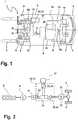
- FIG. 1 is an internal combustion engine-electrically powered truck 1 in the form of a counterbalanced forklift shown as an example of a vehicle with at least electric drive in a plan view with the main units of the drive, in which an inventive electrical energy storage 17 is used.
- the truck 1 has a vehicle frame 2, which is provided in the load-facing area with two drive wheels 3 and in the area facing away from the load with steered wheels 4.
- a mast 5 is arranged on which a trained as a load lifting device 6 is arranged movable up and down.
- the truck 1 is provided with a counterweight 7.
- the truck 1 is provided with an internal combustion engine-electric drive system comprising an electric traction drive unit.
- the traction drive unit has a power supply unit that is powered by an internal combustion engine 8, e.g. a diesel engine, and a synchronous generator 9 connected and driven with the engine 8.
- the electrical energy generated by the synchronous generator 9 is supplied via a rectifier 11 of the power electronics 10 integrated in a housing 12, by means of which at least one is arranged in or on a drive axle 14 electric traction drive motor 13, for example, an asynchronous three-phase motor, is supplied with electrical energy.
- the traction drive motor 13 is connected to the drive wheels 3 with the interposition of a differential gear 31 and two reduction gear 30.
- a dual-motor axle can also be provided, in each of which a traction drive motor with the interposition of a reduction gear is in communication with the corresponding drive wheel 3.
- the internal combustion engine 8, the generator 9 and the housing 12 and the drive axle 14 are in this case arranged together with other components, not shown, in a unit space 33 of the truck 1.
- the internal combustion engine 8 is provided with a liquid cooling.
- the liquid cooling has a heat exchanger 15 which is arranged, for example, in the region of the counterweight 7 and which is connected to the internal combustion engine 8 in cooling circuits 16.
- the heat exchanger 15 is traversed by means of a cooling fan 20 of air to increase the deliverable from the cooling liquid to the ambient heat amount of heat.
- the truck 1 is a hybrid vehicle in which power is generated during braking via the traction drive motor 13, which is stored in the electrical energy storage 17 and, e.g. is supplied to the traction drive motor 13 via the power electronics 10 in addition to the power generated by the engine 8 and the synchronous generator 9 at high power requirements.
- the internal combustion engine 8 can be made smaller and still a large power, e.g. can be achieved during short acceleration of the truck 1.
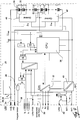
- Fig. 2 schematically shows the structure of the drive system of the truck 1 from the Fig. 1 ,
- the internal combustion engine 8 drives the generator 9 designed as a synchronous generator and the three-phase current generated by the generator 9 is rectified in the rectifier 11 and supplied to the power electronics 10 arranged in the housing 12.
- An inverter 18 as the first inverter 19 forms from the DC voltage of the formed as a DC intermediate circuit DC link 21 three-phase three-phase variable frequency, with which the traction drive motor 13 is fed, which drives the drive wheels 3 via the differential gear 31.
- a arranged in the housing 12 capacitor 22 serves as an input filter, which also forms the input filter of a DC-DC converter 23, which is integrated as a second converter or actuator 24 in the housing 12 and the electrical energy storage 17 is connected.
- the Fig. 3 shows a perspective view of an electrical energy storage 17.
- a housing 25 all components and components of the electrical energy storage described are summarized, in particular, the controller and the data bus controller.
- the housing 25 has on its upper side as well as underside cooling ribs 26.
- the cooling capacity can be increased by an integrated cooling, such as a fan or a heat exchanger with a liquid cooling, wherein, for example, the fan or the heat exchanger can also be integrated into the housing.
- the housing 25 has connections 27 for a CAN bus, the power connections and other lines.
- the Fig. 4 shows a circuit diagram of the electrical energy storage 17 of Fig. 1 and Fig. 3 ,
- a contactor 28 may interrupt the positive lead 29 of power terminals 34.
- Units of ultracapacitors 35 are connected in series. Temperatures of the ultracapacitors 35 are supplied to a controller 36, which is connected via a CAN data bus transceiver 37 to a vehicle controller and can exchange information about the operating state of the electrical energy store 17 with this.
- the contactor 28 Via a signal line 38, the contactor 28 can be released from a switching or ignition lock or an emergency stop switch, so that the contactor 28 can only turn on when this signal is present.
- a further data line 39 an actuation of the contactor 28 by the switching mechanism or the emergency stop switch.
- the energy store 17 is further provided with a total voltage measurement U cap and a current measurement I cap by the controller 36.
- a plurality of temperature sensors 40 are provided which are in communication with the controller 36 and are distributed uniformly in the energy store 17.
- the controller 36 and the CAN data bus transceiver 37 are provided with a low voltage terminal 41 that enables the connection of a switching power supply 43 to the vehicle battery of the vehicle. To avoid discharging the vehicle battery, the switching power supply 43 can be switched off by the controller 36.
- the energy store 17 is furthermore provided with a connection 42 for a fan for external cooling of the energy store 17.
- the energy storage 17 is provided with a tracking function for monitoring the temperature sensors 40 and for possibly necessary control of the fan connected to the terminal 42.
- the controller 36 may further enable or disable the equalization circuit of each ultracapacitor 35. As a result, any operating strategies can be run, which serves the balancing and ensuring a uniform aging of the ultracapacitors 35.
- control circuit with the monitoring circuit by potential-separating coupling elements and the switching power supply 43 is constructed separately from the vehicle electrical system potential.
- the energy store 17 makes it possible, by means of the integrated contactor 28, for the energy store 17 to be disconnected from the vehicle drive train by a forced opening of the contactor 28 in the event of short circuits and / or limit values exceeding voltages or currents.
- the electrical energy storage device 17 has the ability to self-diagnose and is easy to integrate into a vehicle system.
- Two coding bridges which can be integrated in the cable set, make it possible to connect up to four identical electrical energy stores in series. In the installed state, it is possible by means of the cable bridges to allocate the error messages precisely to individual electrical energy stores, so that e.g. a service technician can see exactly what electrical energy storage is affected in the event of a fault.
Landscapes
- Engineering & Computer Science (AREA)
- Power Engineering (AREA)
- Transportation (AREA)
- Mechanical Engineering (AREA)
- Life Sciences & Earth Sciences (AREA)
- Sustainable Development (AREA)
- Sustainable Energy (AREA)
- Electric Propulsion And Braking For Vehicles (AREA)
Applications Claiming Priority (2)
| Application Number | Priority Date | Filing Date | Title |
|---|---|---|---|
| DE102011011621 | 2011-02-17 | ||
| DE102011013836A DE102011013836A1 (de) | 2011-02-17 | 2011-03-14 | Elektrischer Energiespeicher für Fahrzeug mit elektrischem Antrieb |
Publications (2)
| Publication Number | Publication Date |
|---|---|
| EP2500206A2 true EP2500206A2 (fr) | 2012-09-19 |
| EP2500206A3 EP2500206A3 (fr) | 2018-01-17 |
Family
ID=46605039
Family Applications (1)
| Application Number | Title | Priority Date | Filing Date |
|---|---|---|---|
| EP12152393.0A Withdrawn EP2500206A3 (fr) | 2011-02-17 | 2012-01-25 | Accumulateur d'énergie électrique pour véhicule doté d'un entraînement électrique |
Country Status (2)
| Country | Link |
|---|---|
| EP (1) | EP2500206A3 (fr) |
| DE (1) | DE102011013836A1 (fr) |
Cited By (1)
| Publication number | Priority date | Publication date | Assignee | Title |
|---|---|---|---|---|
| WO2019040526A1 (fr) * | 2017-08-22 | 2019-02-28 | Maxwell Technologies, Inc. | Système et procédé pour fournir un support de tension transitoire bidirectionnel et de l'énergie |
Families Citing this family (2)
| Publication number | Priority date | Publication date | Assignee | Title |
|---|---|---|---|---|
| CN112531470B (zh) * | 2020-12-11 | 2023-01-03 | 中车大连电力牵引研发中心有限公司 | 高压转换开关箱 |
| DE102022100297A1 (de) | 2022-01-07 | 2023-07-13 | Jungheinrich Aktiengesellschaft | Flurförderzeug, Traktionsbatterie und Verfahren zum Betreiben eines Flurförderzeugs |
Family Cites Families (6)
| Publication number | Priority date | Publication date | Assignee | Title |
|---|---|---|---|---|
| JPH10337084A (ja) * | 1997-05-30 | 1998-12-18 | Aisin Seiki Co Ltd | スイッチングモジュ−ルの過熱保護装置 |
| US7427450B2 (en) * | 2004-12-10 | 2008-09-23 | General Motors Corporation | Hybrid fuel cell system with battery capacitor energy storage system |
| DE102007043071A1 (de) * | 2007-09-10 | 2009-03-12 | Robert Bosch Gmbh | Energiespeichermodul für ein elektrisches Energieversorgungsnetz eines Kraftfahrzeugs |
| DE102008012418A1 (de) * | 2008-02-29 | 2009-09-03 | Volkswagen Ag | Hochvoltsystem in einem Kraftfahrzeug und Verfahren zur Überprüfung der Kontaktierung einer Hochvoltbatterie mit den Hochvoltleitungen eines Hochvoltsystems |
| KR101128423B1 (ko) * | 2008-04-28 | 2012-03-23 | 에스케이이노베이션 주식회사 | 전기자동차용 2차 전지의 안전 스위치 및 이를 이용한전기자동차용 2차 전지의 충방전 시스템 |
| DE102011107057A1 (de) * | 2011-05-02 | 2012-11-08 | Still Gmbh | Elektrischer Energiespeicher für Fahrzeug mit elektrischem Antrieb |
-
2011
- 2011-03-14 DE DE102011013836A patent/DE102011013836A1/de not_active Withdrawn
-
2012
- 2012-01-25 EP EP12152393.0A patent/EP2500206A3/fr not_active Withdrawn
Non-Patent Citations (1)
| Title |
|---|
| None |
Cited By (4)
| Publication number | Priority date | Publication date | Assignee | Title |
|---|---|---|---|---|
| WO2019040526A1 (fr) * | 2017-08-22 | 2019-02-28 | Maxwell Technologies, Inc. | Système et procédé pour fournir un support de tension transitoire bidirectionnel et de l'énergie |
| CN111164848A (zh) * | 2017-08-22 | 2020-05-15 | 麦斯韦尔技术股份有限公司 | 用于提供双向瞬态电压支持和电力的系统和方法 |
| US10797503B2 (en) | 2017-08-22 | 2020-10-06 | Maxwell Technologies, Inc. | System and method for providing bidirectional transient voltage support and power |
| CN111164848B (zh) * | 2017-08-22 | 2025-09-05 | 麦斯韦尔技术股份有限公司 | 用于提供双向瞬态电压支持和电力的系统和方法 |
Also Published As
| Publication number | Publication date |
|---|---|
| EP2500206A3 (fr) | 2018-01-17 |
| DE102011013836A1 (de) | 2012-08-23 |
Similar Documents
| Publication | Publication Date | Title |
|---|---|---|
| EP2477839B1 (fr) | Procédé et dispositif pour faire fonctionner un véhicule hybride en cas de défaillance d'un système d'alimentation en énergie | |
| DE102012110524B4 (de) | Elektrisches Ladesystem und Elektrofahrzeug | |
| DE102004057693B4 (de) | Vorrichtung zur schnellen Entladung eines Kondensators | |
| WO2012052176A2 (fr) | Système de gestion de batterie pour système d'alimentation électrique comprenant une zone basse tension et une zone haute tension | |
| EP2539989B1 (fr) | Système d'entraînement et machine de travail | |
| DE102012204866A1 (de) | Verfahren und Vorrichtung zur Diagnose einer Entladeschaltung eines elektrischen Systems | |
| WO2011135036A2 (fr) | Système de véhicule modulaire | |
| EP3320204B1 (fr) | Intégration d'une commande de courant de démarrage et d'un sectionneur de réseau de bord | |
| DE102015004701A1 (de) | Elektrofahrzeug mit Schnellladefunktion | |
| EP2433830A1 (fr) | Procédé de commande pour la préparation d'énergie électrique à partir d'une machine synchrone triphasée entraînée | |
| DE102011006395A1 (de) | Verfahren zum Betrieb des Bordnetzes in Hybrid- oder Elektrofahrzeugen bei einem Ausfall von einem oder mehreren Elementen eines Überwachungssystems der Traktionsbatterie | |
| AT523261B1 (de) | Akkumulatorsystem mit einem Leistungsakkumulator für fahrbare Arbeitsmaschinen | |
| DE102011013836A1 (de) | Elektrischer Energiespeicher für Fahrzeug mit elektrischem Antrieb | |
| EP3990305A1 (fr) | Véhicule et procédé pour faire fonctionner un véhicule | |
| EP2612394A1 (fr) | Système d'accumulation d'énergie électrique | |
| WO2011023264A1 (fr) | Système d'accumulation d'énergie électrique | |
| DE102011017274B4 (de) | Verfahren, Energiespeichereinrichtungsmanagementsystem und Schaltungsanordnung zum Laden einer Fahrzeugbatterie bei ausgeschaltetem Bordnetz | |
| EP2500207A2 (fr) | Véhicule doté d'un entraînement électrique et d'un accumulateur d'énergie | |
| EP3536547B1 (fr) | Chariot de manutention fonctionnant sur batterie électrique pourvu de batterie tampon destinée à l'alimentation du réseau de bord | |
| EP1946433B1 (fr) | Onduleur a impulsions utilise dans le fonctionnement au gazogene d'urgence | |
| DE102022214148A1 (de) | Schaltvorrichtung, Schaltsystem, Antriebsstrang und Fahrzeug | |
| EP3972870A1 (fr) | Procédé servant à augmenter la capacité de fourniture d'un couple de freinage électrique d'au moins une machine électrique | |
| DE102011077306A1 (de) | Energiesystem für ein Fahrzeug, Verfahren zur Minderung der Ladung einer Batterie und Kraftfahrzeug | |
| EP3075593B1 (fr) | Procede de dechargement d'un accumulateur d'energie electrique de vehicule automobile | |
| DE102012015941B4 (de) | Kraftfahrzeug |
Legal Events
| Date | Code | Title | Description |
|---|---|---|---|
| PUAI | Public reference made under article 153(3) epc to a published international application that has entered the european phase |
Free format text: ORIGINAL CODE: 0009012 |
|
| AK | Designated contracting states |
Kind code of ref document: A2 Designated state(s): AL AT BE BG CH CY CZ DE DK EE ES FI FR GB GR HR HU IE IS IT LI LT LU LV MC MK MT NL NO PL PT RO RS SE SI SK SM TR |
|
| AX | Request for extension of the european patent |
Extension state: BA ME |
|
| PUAL | Search report despatched |
Free format text: ORIGINAL CODE: 0009013 |
|
| AK | Designated contracting states |
Kind code of ref document: A3 Designated state(s): AL AT BE BG CH CY CZ DE DK EE ES FI FR GB GR HR HU IE IS IT LI LT LU LV MC MK MT NL NO PL PT RO RS SE SI SK SM TR |
|
| AX | Request for extension of the european patent |
Extension state: BA ME |
|
| RIC1 | Information provided on ipc code assigned before grant |
Ipc: B60L 11/12 20060101ALI20171208BHEP Ipc: B60L 11/00 20060101ALI20171208BHEP Ipc: B60L 11/18 20060101AFI20171208BHEP Ipc: H02J 7/00 20060101ALI20171208BHEP Ipc: H02J 7/34 20060101ALI20171208BHEP |
|
| STAA | Information on the status of an ep patent application or granted ep patent |
Free format text: STATUS: REQUEST FOR EXAMINATION WAS MADE |
|
| 17P | Request for examination filed |
Effective date: 20180716 |
|
| RBV | Designated contracting states (corrected) |
Designated state(s): AL AT BE BG CH CY CZ DE DK EE ES FI FR GB GR HR HU IE IS IT LI LT LU LV MC MK MT NL NO PL PT RO RS SE SI SK SM TR |
|
| STAA | Information on the status of an ep patent application or granted ep patent |
Free format text: STATUS: THE APPLICATION IS DEEMED TO BE WITHDRAWN |
|
| 18D | Application deemed to be withdrawn |
Effective date: 20190801 |