EP2500207A2 - Véhicule doté d'un entraînement électrique et d'un accumulateur d'énergie - Google Patents
Véhicule doté d'un entraînement électrique et d'un accumulateur d'énergie Download PDFInfo
- Publication number
- EP2500207A2 EP2500207A2 EP12152394A EP12152394A EP2500207A2 EP 2500207 A2 EP2500207 A2 EP 2500207A2 EP 12152394 A EP12152394 A EP 12152394A EP 12152394 A EP12152394 A EP 12152394A EP 2500207 A2 EP2500207 A2 EP 2500207A2
- Authority
- EP
- European Patent Office
- Prior art keywords
- module
- electrical energy
- vehicle
- vehicle according
- energy storage
- Prior art date
- Legal status (The legal status is an assumption and is not a legal conclusion. Google has not performed a legal analysis and makes no representation as to the accuracy of the status listed.)
- Withdrawn
Links
Images

Classifications
-
- H—ELECTRICITY
- H02—GENERATION; CONVERSION OR DISTRIBUTION OF ELECTRIC POWER
- H02J—ELECTRIC POWER NETWORKS; CIRCUIT ARRANGEMENTS OR SYSTEMS FOR SUPPLYING OR DISTRIBUTING ELECTRIC POWER; SYSTEMS FOR STORING ELECTRIC ENERGY
- H02J7/00—Circuit arrangements for charging or discharging batteries or for supplying loads from batteries
- H02J7/34—Parallel operation in networks using both storage and other DC sources, e.g. providing buffering
- H02J7/345—Parallel operation in networks using both storage and other DC sources, e.g. providing buffering using capacitors as storage or buffering devices
-
- B—PERFORMING OPERATIONS; TRANSPORTING
- B60—VEHICLES IN GENERAL
- B60L—PROPULSION OF ELECTRICALLY-PROPELLED VEHICLES; SUPPLYING ELECTRIC POWER FOR AUXILIARY EQUIPMENT OF ELECTRICALLY-PROPELLED VEHICLES; ELECTRODYNAMIC BRAKE SYSTEMS FOR VEHICLES IN GENERAL; MAGNETIC SUSPENSION OR LEVITATION FOR VEHICLES; MONITORING OPERATING VARIABLES OF ELECTRICALLY-PROPELLED VEHICLES; ELECTRIC SAFETY DEVICES FOR ELECTRICALLY-PROPELLED VEHICLES
- B60L50/00—Electric propulsion with power supplied within the vehicle
- B60L50/40—Electric propulsion with power supplied within the vehicle using propulsion power supplied by capacitors
-
- B—PERFORMING OPERATIONS; TRANSPORTING
- B60—VEHICLES IN GENERAL
- B60L—PROPULSION OF ELECTRICALLY-PROPELLED VEHICLES; SUPPLYING ELECTRIC POWER FOR AUXILIARY EQUIPMENT OF ELECTRICALLY-PROPELLED VEHICLES; ELECTRODYNAMIC BRAKE SYSTEMS FOR VEHICLES IN GENERAL; MAGNETIC SUSPENSION OR LEVITATION FOR VEHICLES; MONITORING OPERATING VARIABLES OF ELECTRICALLY-PROPELLED VEHICLES; ELECTRIC SAFETY DEVICES FOR ELECTRICALLY-PROPELLED VEHICLES
- B60L50/00—Electric propulsion with power supplied within the vehicle
- B60L50/50—Electric propulsion with power supplied within the vehicle using propulsion power supplied by batteries or fuel cells
- B60L50/60—Electric propulsion with power supplied within the vehicle using propulsion power supplied by batteries or fuel cells using power supplied by batteries
- B60L50/61—Electric propulsion with power supplied within the vehicle using propulsion power supplied by batteries or fuel cells using power supplied by batteries by batteries charged by engine-driven generators, e.g. series hybrid electric vehicles
-
- B—PERFORMING OPERATIONS; TRANSPORTING
- B60—VEHICLES IN GENERAL
- B60L—PROPULSION OF ELECTRICALLY-PROPELLED VEHICLES; SUPPLYING ELECTRIC POWER FOR AUXILIARY EQUIPMENT OF ELECTRICALLY-PROPELLED VEHICLES; ELECTRODYNAMIC BRAKE SYSTEMS FOR VEHICLES IN GENERAL; MAGNETIC SUSPENSION OR LEVITATION FOR VEHICLES; MONITORING OPERATING VARIABLES OF ELECTRICALLY-PROPELLED VEHICLES; ELECTRIC SAFETY DEVICES FOR ELECTRICALLY-PROPELLED VEHICLES
- B60L50/00—Electric propulsion with power supplied within the vehicle
- B60L50/50—Electric propulsion with power supplied within the vehicle using propulsion power supplied by batteries or fuel cells
- B60L50/60—Electric propulsion with power supplied within the vehicle using propulsion power supplied by batteries or fuel cells using power supplied by batteries
- B60L50/64—Constructional details of batteries specially adapted for electric vehicles
-
- B—PERFORMING OPERATIONS; TRANSPORTING
- B60—VEHICLES IN GENERAL
- B60L—PROPULSION OF ELECTRICALLY-PROPELLED VEHICLES; SUPPLYING ELECTRIC POWER FOR AUXILIARY EQUIPMENT OF ELECTRICALLY-PROPELLED VEHICLES; ELECTRODYNAMIC BRAKE SYSTEMS FOR VEHICLES IN GENERAL; MAGNETIC SUSPENSION OR LEVITATION FOR VEHICLES; MONITORING OPERATING VARIABLES OF ELECTRICALLY-PROPELLED VEHICLES; ELECTRIC SAFETY DEVICES FOR ELECTRICALLY-PROPELLED VEHICLES
- B60L58/00—Methods or circuit arrangements for monitoring or controlling batteries or fuel cells, specially adapted for electric vehicles
- B60L58/10—Methods or circuit arrangements for monitoring or controlling batteries or fuel cells, specially adapted for electric vehicles for monitoring or controlling batteries
-
- H—ELECTRICITY
- H02—GENERATION; CONVERSION OR DISTRIBUTION OF ELECTRIC POWER
- H02J—ELECTRIC POWER NETWORKS; CIRCUIT ARRANGEMENTS OR SYSTEMS FOR SUPPLYING OR DISTRIBUTING ELECTRIC POWER; SYSTEMS FOR STORING ELECTRIC ENERGY
- H02J7/00—Circuit arrangements for charging or discharging batteries or for supplying loads from batteries
- H02J7/60—Circuit arrangements for charging or discharging batteries or for supplying loads from batteries including safety or protection arrangements
- H02J7/663—Circuit arrangements for charging or discharging batteries or for supplying loads from batteries including safety or protection arrangements using battery or load disconnect circuits
-
- B—PERFORMING OPERATIONS; TRANSPORTING
- B60—VEHICLES IN GENERAL
- B60L—PROPULSION OF ELECTRICALLY-PROPELLED VEHICLES; SUPPLYING ELECTRIC POWER FOR AUXILIARY EQUIPMENT OF ELECTRICALLY-PROPELLED VEHICLES; ELECTRODYNAMIC BRAKE SYSTEMS FOR VEHICLES IN GENERAL; MAGNETIC SUSPENSION OR LEVITATION FOR VEHICLES; MONITORING OPERATING VARIABLES OF ELECTRICALLY-PROPELLED VEHICLES; ELECTRIC SAFETY DEVICES FOR ELECTRICALLY-PROPELLED VEHICLES
- B60L2200/00—Type of vehicles
- B60L2200/40—Working vehicles
- B60L2200/42—Fork lift trucks
-
- B—PERFORMING OPERATIONS; TRANSPORTING
- B60—VEHICLES IN GENERAL
- B60L—PROPULSION OF ELECTRICALLY-PROPELLED VEHICLES; SUPPLYING ELECTRIC POWER FOR AUXILIARY EQUIPMENT OF ELECTRICALLY-PROPELLED VEHICLES; ELECTRODYNAMIC BRAKE SYSTEMS FOR VEHICLES IN GENERAL; MAGNETIC SUSPENSION OR LEVITATION FOR VEHICLES; MONITORING OPERATING VARIABLES OF ELECTRICALLY-PROPELLED VEHICLES; ELECTRIC SAFETY DEVICES FOR ELECTRICALLY-PROPELLED VEHICLES
- B60L2200/00—Type of vehicles
- B60L2200/40—Working vehicles
- B60L2200/44—Industrial trucks or floor conveyors
-
- B—PERFORMING OPERATIONS; TRANSPORTING
- B60—VEHICLES IN GENERAL
- B60L—PROPULSION OF ELECTRICALLY-PROPELLED VEHICLES; SUPPLYING ELECTRIC POWER FOR AUXILIARY EQUIPMENT OF ELECTRICALLY-PROPELLED VEHICLES; ELECTRODYNAMIC BRAKE SYSTEMS FOR VEHICLES IN GENERAL; MAGNETIC SUSPENSION OR LEVITATION FOR VEHICLES; MONITORING OPERATING VARIABLES OF ELECTRICALLY-PROPELLED VEHICLES; ELECTRIC SAFETY DEVICES FOR ELECTRICALLY-PROPELLED VEHICLES
- B60L2240/00—Control parameters of input or output; Target parameters
- B60L2240/40—Drive Train control parameters
- B60L2240/54—Drive Train control parameters related to batteries
- B60L2240/545—Temperature
-
- H—ELECTRICITY
- H02—GENERATION; CONVERSION OR DISTRIBUTION OF ELECTRIC POWER
- H02J—ELECTRIC POWER NETWORKS; CIRCUIT ARRANGEMENTS OR SYSTEMS FOR SUPPLYING OR DISTRIBUTING ELECTRIC POWER; SYSTEMS FOR STORING ELECTRIC ENERGY
- H02J7/00—Circuit arrangements for charging or discharging batteries or for supplying loads from batteries
- H02J7/40—Circuit arrangements for charging or discharging batteries or for supplying loads from batteries characterised by the exchange of charge or discharge related data
- H02J7/443—Circuit arrangements for charging or discharging batteries or for supplying loads from batteries characterised by the exchange of charge or discharge related data using passive battery identification means, e.g. resistors or capacitors
-
- H—ELECTRICITY
- H02—GENERATION; CONVERSION OR DISTRIBUTION OF ELECTRIC POWER
- H02J—ELECTRIC POWER NETWORKS; CIRCUIT ARRANGEMENTS OR SYSTEMS FOR SUPPLYING OR DISTRIBUTING ELECTRIC POWER; SYSTEMS FOR STORING ELECTRIC ENERGY
- H02J7/00—Circuit arrangements for charging or discharging batteries or for supplying loads from batteries
- H02J7/485—Circuit arrangements for charging or discharging batteries or for supplying loads from batteries with provisions for charging different types of batteries
-
- Y—GENERAL TAGGING OF NEW TECHNOLOGICAL DEVELOPMENTS; GENERAL TAGGING OF CROSS-SECTIONAL TECHNOLOGIES SPANNING OVER SEVERAL SECTIONS OF THE IPC; TECHNICAL SUBJECTS COVERED BY FORMER USPC CROSS-REFERENCE ART COLLECTIONS [XRACs] AND DIGESTS
- Y02—TECHNOLOGIES OR APPLICATIONS FOR MITIGATION OR ADAPTATION AGAINST CLIMATE CHANGE
- Y02P—CLIMATE CHANGE MITIGATION TECHNOLOGIES IN THE PRODUCTION OR PROCESSING OF GOODS
- Y02P90/00—Enabling technologies with a potential contribution to greenhouse gas [GHG] emissions mitigation
- Y02P90/60—Electric or hybrid propulsion means for production processes
-
- Y—GENERAL TAGGING OF NEW TECHNOLOGICAL DEVELOPMENTS; GENERAL TAGGING OF CROSS-SECTIONAL TECHNOLOGIES SPANNING OVER SEVERAL SECTIONS OF THE IPC; TECHNICAL SUBJECTS COVERED BY FORMER USPC CROSS-REFERENCE ART COLLECTIONS [XRACs] AND DIGESTS
- Y02—TECHNOLOGIES OR APPLICATIONS FOR MITIGATION OR ADAPTATION AGAINST CLIMATE CHANGE
- Y02T—CLIMATE CHANGE MITIGATION TECHNOLOGIES RELATED TO TRANSPORTATION
- Y02T10/00—Road transport of goods or passengers
- Y02T10/60—Other road transportation technologies with climate change mitigation effect
- Y02T10/62—Hybrid vehicles
-
- Y—GENERAL TAGGING OF NEW TECHNOLOGICAL DEVELOPMENTS; GENERAL TAGGING OF CROSS-SECTIONAL TECHNOLOGIES SPANNING OVER SEVERAL SECTIONS OF THE IPC; TECHNICAL SUBJECTS COVERED BY FORMER USPC CROSS-REFERENCE ART COLLECTIONS [XRACs] AND DIGESTS
- Y02—TECHNOLOGIES OR APPLICATIONS FOR MITIGATION OR ADAPTATION AGAINST CLIMATE CHANGE
- Y02T—CLIMATE CHANGE MITIGATION TECHNOLOGIES RELATED TO TRANSPORTATION
- Y02T10/00—Road transport of goods or passengers
- Y02T10/60—Other road transportation technologies with climate change mitigation effect
- Y02T10/70—Energy storage systems for electromobility, e.g. batteries
Definitions
- the invention relates to a vehicle with at least an electric drive, in particular a hybrid drive, with an electrical energy store which has a plurality of ultracapacitors which are integrated as a module in a housing.
- traction drive In internal combustion engine operated industrial trucks can be provided for the traction drive mechanical power transmission with a hydrodynamic converter gear or a hydrostatic transmission.
- electric power transmission for the traction drive is known in which one of the internal combustion engine, e.g. a diesel engine, driven generator feeds an electrical DC link, from which a traction drive motor is fed.
- the traction drive motor is a three-phase motor, for example, an asynchronous motor, which is fed via an inverter from the DC link.
- Such an internal combustion engine electric truck offers simple conditions to an electrical energy storage, e.g. to store the braking energy, to integrate.
- an electrical energy storage e.g. to store the braking energy
- the electrical energy storage may e.g. consist of ultracapacitors or batteries.
- Industrial trucks with a combustion engine-electric drive system described above with an additional electrical energy storage can also on simple way as hybrid trucks are operated by high power requirements in addition to the engine, for example, to supply the traction drive motor or via the motor operated as a generator to support the engine when driving other units, such as a hydraulic power supply hydraulic pump, electrical energy to the electrical energy storage is removed.
- the internal combustion engine can then be designed smaller in performance accordingly.
- an additional electrical energy storage can also be an industrial truck with an internal combustion engine drive system and a hydrostatic drive or hydrodynamic traction drive are designed as a hybrid vehicle when an additional electric motor is used as a drive motor or to support the engine as the electric drive.
- an ultracapacitors or double-layer capacitors using energy storage As an electrical energy storage is particularly suitable for short driving cycles, an ultracapacitors or double-layer capacitors using energy storage. Since the ultracapacitors only a max. Allow cell voltage of about 2.7 V, several ultracapacitors must be connected in series to obtain a suitable electrical energy storage.
- the present invention is therefore based on the object, a vehicle with electric drive and energy storage and in particular a system Provide vehicles and electrical energy storage available with which can be done in a cost effective manner and with little development effort to adapt to different performance requirements in the vehicles.
- the object is achieved by a vehicle with an at least electric drive, in particular a hybrid drive, with an electrical energy store, which has a plurality of ultracapacitors, which are integrated as a module in a housing.
- the electrical energy store is formed from a plurality of modules which are connected in parallel or in series.
- the power of the electrical energy store can be adapted to the requirements in a very simple manner.
- a large number of completely identical modules can be used. This results in economically favorable large quantities. It can e.g. several, especially four, modules are connected in series.
- the vehicle is a mobile work machine, in particular an industrial truck.
- each module has a coding, in particular none, one or two coding bridges, which are integrated in the cable set of the connecting cable.
- each module has a contactor or switch, which can be switched via a control line and / or a control signal and disconnect a power connection of the module.
- Each module can be installed in any position in the vehicle.
- the contactor ensures that the module, the electrical energy storage as a whole, as well as the vehicle are protected in the event of a short circuit.
- Each module may include a controller that detects functional parameters of the ultracapacitors such as temperature and / or voltage and / or currents.
- the controller can switch off the module in case of detected short circuits and / or exceeding admissible limit values for temperature and / or voltage and / or currents of the ultracapacitors.
- a data bus controller in particular a CAN controller and on this function parameters can be read and receive control commands and / or it can be a coding of the module.
- the control functions of controllers may be independent of the circuit of the contactor and / or the state of charge of the ultracapacitors.
- the temperature of the ultracapacitors can be further monitored if a follow-up function for monitoring the temperature sensors, further function parameter values, or for controlling a cooling fan for the cooling of the modules is provided.
- the ultracapacitors are double-layer capacitors.
- the object is also achieved by a system comprising at least two vehicles described above, wherein the vehicles are different in terms of the power requirements of the electrical energy storage and the electrical energy storage has a number of modules dependent on the required power.
- the vehicles are industrial trucks, in particular counterbalance forklifts, which differ in the empty weight and permissible load weight.
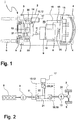
- FIG. 1 is an internal combustion engine-electrically powered truck 1 in the form of a counterbalance forklift shown as an example of a vehicle according to the invention with at least electric drive in a plan view with the main units of the drive and an electric energy storage 17.
- the truck 1 has a vehicle frame 2, which is provided in the load-facing area with two drive wheels 3 and in the area facing away from the load with steered wheels 4.
- a mast 5 is arranged on which a trained as a load lifting device 6 is arranged movable up and down.
- the truck 1 is provided with a counterweight 7.
- the truck 1 is provided with an internal combustion engine-electric drive system comprising an electric traction drive unit.
- the traction drive unit has a power supply unit that is powered by an internal combustion engine 8, e.g. a diesel engine, and a synchronous generator 9 connected and driven with the engine 8.
- the electrical energy generated by the synchronous generator 9 is supplied via a rectifier 11 of the power electronics 10 integrated in a housing 12, by means of which at least one arranged in or on a drive axle 14 electric traction motor 13, for example, an asynchronous three-phase motor, is supplied with electrical energy.
- the traction drive motor 13 is connected to the drive wheels 3 with the interposition of a differential gear 31 and two reduction gear 30.
- a dual-motor axle can also be provided, in each case one Traction drive motor with the interposition of a reduction gear with the corresponding drive wheel 3 is in communication.
- the internal combustion engine 8, the generator 9 and the housing 12 and the drive axle 14 are in this case arranged together with other components, not shown, in a unit space 33 of the truck 1.
- the internal combustion engine 8 is provided with a liquid cooling.
- the liquid cooling has a heat exchanger 15 which is arranged, for example, in the region of the counterweight 7 and which is connected to the internal combustion engine 8 in cooling circuits 16.
- the heat exchanger 15 is traversed by means of a cooling fan 20 of air to increase the deliverable from the cooling liquid to the ambient heat amount of heat.
- the truck 1 is a hybrid vehicle in which power is generated during braking via the traction drive motor 13, which is stored in the electrical energy storage 17 and, e.g. is supplied to the traction drive motor 13 via the power electronics 10 in addition to the power generated by the engine 8 and the synchronous generator 9 at high power requirements.
- the internal combustion engine 8 can be made smaller and still a large power, e.g. can be achieved during short acceleration of the truck 1.
- Fig. 2 schematically shows the structure of the drive system of the truck 1 from the Fig. 1 ,
- the internal combustion engine 8 drives the generator 9 designed as a synchronous generator.
- the three-phase current generated by the generator 9 is rectified in the rectifier 11 and supplied to the arranged in the housing 12 power electronics 10.
- An inverter 18 as the first converter 19 forms from the DC voltage of the intermediate circuit formed as a DC intermediate circuit 21 three-phase three-phase variable frequency, with which the traction drive motor 13 is fed, which drives the drive wheels 3 via the differential gear 31.
- a arranged in the housing 12 capacitor 22 serves as an input filter, which also forms the input filter of a DC-DC converter 23, which is integrated as a second inverter 24 or actuator in the housing 12 and the electrical energy storage 17 is connected.
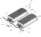
- the Fig. 3 shows a perspective view of an electrical energy storage 17, which is formed of several, in the illustrated embodiment of two series-connected modules 44.
- a housing 25 all the described components and components of a module 44 are summarized, in particular also the controller and the data bus controller.
- the housing 25 has on its upper side as well as underside cooling ribs 26.
- the cooling capacity can be increased by an integrated cooling, such as a fan or a heat exchanger with a liquid cooling, wherein, for example, the fan or the heat exchanger can also be integrated into the housing.
- the housing 25 of each module 44 has terminals 27 for a CAN bus, the power terminals and their leads 45, to which the modules 44 are connected in series.
- the Fig. 4 shows a circuit diagram of a module 44 of Fig. 3
- a contactor 28 may interrupt the positive lead 29 of power terminals 34.
- Units of ultracapacitors 35 are connected in series. Temperatures of the ultracapacitors 35 are supplied to a controller 36, which is connected via a CAN data bus transceiver 37 to a vehicle controller and can exchange information about the operating state of the electrical energy store 17 or of the modules 44 with the latter.
- the contactor 28 Via a signal line 38, the contactor 28 can be released from a switching or ignition lock or an emergency stop switch, so that the contactor 28 can only turn on when this signal is present.
- a further data line 39 an actuation of the contactor 28 by the switching mechanism or the emergency stop switch.
- the module 44 is further provided with a total voltage measurement U cap and a current measurement I cap by the controller 36.
- a plurality of temperature sensors 40 are provided, which are in communication with the controller 36, and are evenly distributed in the module 44.
- the controller 36 and the CAN data bus transceiver 37 are provided with a low voltage terminal 41, which allows the connection of a switching power supply 43 to the vehicle battery of the vehicle. To avoid discharging the vehicle battery, the switching power supply 43 can be switched off by the controller 36.
- the module 44 is further provided with a Terminal 42 provided for a fan for external cooling of the module 44.
- the module 44 In order to monitor the temperature when the vehicle is parked, the module 44 is provided with a tracking function for monitoring the temperature sensors 40 and for possibly necessary control of the fan 42 connected to the terminal.
- the controller 36 may further enable or disable the equalization circuit of each ultracapacitor 34. As a result, any operating strategies can be run, which serves the balancing and ensuring a uniform aging of the ultracapacitors 34.
- module 44 is that of the components in the FIG. 4 Links formed the ultracapacitors 34 control circuit with the monitoring circuit by potential-separating coupling elements and the switching power supply 43 from the vehicle electrical system potential built separately.
- the module 44 allows through the integrated contactor 28, that the energy storage 17 at short circuits and / or thresholds exceeding voltages or currents can be separated by a positive opening of the contactor 28 of the vehicle drive train.
- modules 44 may be used in series or in parallel to accommodate required voltages and power ratings. It results in the inventive electrical energy storage 17, consisting of several modules 44, a compact overall design and good handling for service personnel and in case of repair.
- the module 44 has the ability to self-diagnose and is easy to integrate into a vehicle system.
- the individual modules 44 are completely identical and are individualized and identified only by being connected to the respective connector. Depending on the method of coding, more than four modules can be interconnected. Identical modules 44 for different industrial trucks 1 within a system in the sense of a modular system can be used.
Landscapes
- Engineering & Computer Science (AREA)
- Power Engineering (AREA)
- Transportation (AREA)
- Mechanical Engineering (AREA)
- Life Sciences & Earth Sciences (AREA)
- Sustainable Development (AREA)
- Sustainable Energy (AREA)
- Electric Propulsion And Braking For Vehicles (AREA)
Applications Claiming Priority (2)
| Application Number | Priority Date | Filing Date | Title |
|---|---|---|---|
| DE102011011620 | 2011-02-17 | ||
| DE102011013837A DE102011013837A1 (de) | 2011-02-17 | 2011-03-14 | Fahrzeug mit elektrischem Antrieb und Energiespeicher |
Publications (2)
| Publication Number | Publication Date |
|---|---|
| EP2500207A2 true EP2500207A2 (fr) | 2012-09-19 |
| EP2500207A3 EP2500207A3 (fr) | 2018-02-07 |
Family
ID=46605040
Family Applications (1)
| Application Number | Title | Priority Date | Filing Date |
|---|---|---|---|
| EP12152394.8A Withdrawn EP2500207A3 (fr) | 2011-02-17 | 2012-01-25 | Véhicule doté d'un entraînement électrique et d'un accumulateur d'énergie |
Country Status (2)
| Country | Link |
|---|---|
| EP (1) | EP2500207A3 (fr) |
| DE (1) | DE102011013837A1 (fr) |
Cited By (1)
| Publication number | Priority date | Publication date | Assignee | Title |
|---|---|---|---|---|
| CN111404174A (zh) * | 2020-04-23 | 2020-07-10 | 安徽新力电气设备有限责任公司 | 超级电容器模组投切装置 |
Family Cites Families (3)
| Publication number | Priority date | Publication date | Assignee | Title |
|---|---|---|---|---|
| US6104967A (en) * | 1997-07-25 | 2000-08-15 | 3M Innovative Properties Company | Fault-tolerant battery system employing intra-battery network architecture |
| JP5301657B2 (ja) * | 2009-03-27 | 2013-09-25 | 株式会社日立製作所 | 蓄電装置 |
| US20100305792A1 (en) * | 2009-05-29 | 2010-12-02 | Ise Corporation | Dynamically Reconfigurable High Power Energy Storage for Hybrid Vehicles |
-
2011
- 2011-03-14 DE DE102011013837A patent/DE102011013837A1/de not_active Withdrawn
-
2012
- 2012-01-25 EP EP12152394.8A patent/EP2500207A3/fr not_active Withdrawn
Non-Patent Citations (1)
| Title |
|---|
| None |
Cited By (1)
| Publication number | Priority date | Publication date | Assignee | Title |
|---|---|---|---|---|
| CN111404174A (zh) * | 2020-04-23 | 2020-07-10 | 安徽新力电气设备有限责任公司 | 超级电容器模组投切装置 |
Also Published As
| Publication number | Publication date |
|---|---|
| DE102011013837A1 (de) | 2012-08-23 |
| EP2500207A3 (fr) | 2018-02-07 |
Similar Documents
| Publication | Publication Date | Title |
|---|---|---|
| EP3952053B1 (fr) | Procédé de fonctionnement d'un système de batterie | |
| DE112013006718B4 (de) | Antriebssteuervorrichtung für Schienenfahrzeug | |
| DE102012204866A1 (de) | Verfahren und Vorrichtung zur Diagnose einer Entladeschaltung eines elektrischen Systems | |
| DE102019207598A1 (de) | Stromversorgungssystem für fahrzeug | |
| WO2012052176A2 (fr) | Système de gestion de batterie pour système d'alimentation électrique comprenant une zone basse tension et une zone haute tension | |
| WO2010128066A2 (fr) | Système d'accumulation d'énergie | |
| DE102012201827A1 (de) | Verfahren und Vorrichtung zur Entladung eines Zwischenkreises eines Spannungsnetzes | |
| DE102013225540A1 (de) | Batterieladevorrichtung für ein motorfahrzeug | |
| EP1641650B1 (fr) | Limiteur de surtension concu pour un convertisseur de courant de traction | |
| DE102015004701A1 (de) | Elektrofahrzeug mit Schnellladefunktion | |
| DE102017204065A1 (de) | Antriebssystem für ein Fahrzeug und Verfahren zum Betrieb eines Antriebssystems | |
| EP4286215A1 (fr) | Technique de connexion variable d'un système d'accumulation d'énergie de traction | |
| DE102020007350A1 (de) | Verfahren zum Betreiben eines elektrischen Fahrzeuges und elektrisches Fahrzeug | |
| DE102012110236A1 (de) | Trennschaltvorrichtung für eine Energieversorgungseinheit eines Flurförderzeugs, Flurförderzeug sowie Steuerungsverfahren | |
| DE102018132549A1 (de) | Fahrzeugleistungssystem mit blockierung von gegen-elektromagnetischen feldern | |
| WO2020260007A1 (fr) | Véhicule et procédé pour faire fonctionner un véhicule | |
| WO2011023264A1 (fr) | Système d'accumulation d'énergie électrique | |
| WO2012028256A1 (fr) | Système d'accumulation d'énergie électrique | |
| EP2500206A2 (fr) | Accumulateur d'énergie électrique pour véhicule doté d'un entraînement électrique | |
| DE102011011798A1 (de) | Verfahren zum Betreiben eines Energiespeichers für ein Fahrzeug sowie entsprechender Energiespeicher, Spannungsversorgung und Fahrzeug | |
| EP2520455A2 (fr) | Accumulateur d'énergie électrique pour véhicule doté d'un entraînement électrique | |
| DE102011013837A1 (de) | Fahrzeug mit elektrischem Antrieb und Energiespeicher | |
| EP4385789A1 (fr) | Dispositif de sécurité et procédé de sécurité avec une unité de séparation pour la batterie d'un véhicule automobile à propulsion électrique | |
| DE102022214148A1 (de) | Schaltvorrichtung, Schaltsystem, Antriebsstrang und Fahrzeug | |
| DE19827455C2 (de) | Bremsanlage für ein Kraftfahrzeug |
Legal Events
| Date | Code | Title | Description |
|---|---|---|---|
| PUAI | Public reference made under article 153(3) epc to a published international application that has entered the european phase |
Free format text: ORIGINAL CODE: 0009012 |
|
| AK | Designated contracting states |
Kind code of ref document: A2 Designated state(s): AL AT BE BG CH CY CZ DE DK EE ES FI FR GB GR HR HU IE IS IT LI LT LU LV MC MK MT NL NO PL PT RO RS SE SI SK SM TR |
|
| AX | Request for extension of the european patent |
Extension state: BA ME |
|
| PUAL | Search report despatched |
Free format text: ORIGINAL CODE: 0009013 |
|
| AK | Designated contracting states |
Kind code of ref document: A3 Designated state(s): AL AT BE BG CH CY CZ DE DK EE ES FI FR GB GR HR HU IE IS IT LI LT LU LV MC MK MT NL NO PL PT RO RS SE SI SK SM TR |
|
| AX | Request for extension of the european patent |
Extension state: BA ME |
|
| RIC1 | Information provided on ipc code assigned before grant |
Ipc: B60L 11/00 20060101ALI20180103BHEP Ipc: B60L 11/12 20060101ALI20180103BHEP Ipc: B60L 11/18 20060101AFI20180103BHEP Ipc: H02J 7/00 20060101ALI20180103BHEP Ipc: H02J 7/34 20060101ALI20180103BHEP |
|
| STAA | Information on the status of an ep patent application or granted ep patent |
Free format text: STATUS: REQUEST FOR EXAMINATION WAS MADE |
|
| 17P | Request for examination filed |
Effective date: 20180730 |
|
| RBV | Designated contracting states (corrected) |
Designated state(s): AL AT BE BG CH CY CZ DE DK EE ES FI FR GB GR HR HU IE IS IT LI LT LU LV MC MK MT NL NO PL PT RO RS SE SI SK SM TR |
|
| STAA | Information on the status of an ep patent application or granted ep patent |
Free format text: STATUS: THE APPLICATION IS DEEMED TO BE WITHDRAWN |
|
| 18D | Application deemed to be withdrawn |
Effective date: 20190801 |