EP2500497B1 - Aktuator für Nutzfahrzeughaube - Google Patents
Aktuator für Nutzfahrzeughaube Download PDFInfo
- Publication number
- EP2500497B1 EP2500497B1 EP12159383.4A EP12159383A EP2500497B1 EP 2500497 B1 EP2500497 B1 EP 2500497B1 EP 12159383 A EP12159383 A EP 12159383A EP 2500497 B1 EP2500497 B1 EP 2500497B1
- Authority
- EP
- European Patent Office
- Prior art keywords
- hood
- actuator
- track
- rod
- work vehicle
- Prior art date
- Legal status (The legal status is an assumption and is not a legal conclusion. Google has not performed a legal analysis and makes no representation as to the accuracy of the status listed.)
- Active
Links
Images


Classifications
-
- E—FIXED CONSTRUCTIONS
- E05—LOCKS; KEYS; WINDOW OR DOOR FITTINGS; SAFES
- E05F—DEVICES FOR MOVING WINGS INTO OPEN OR CLOSED POSITION; CHECKS FOR WINGS; WING FITTINGS NOT OTHERWISE PROVIDED FOR, CONCERNED WITH THE FUNCTIONING OF THE WING
- E05F1/00—Closers or openers for wings, not otherwise provided for in this subclass
- E05F1/08—Closers or openers for wings, not otherwise provided for in this subclass spring-actuated, e.g. for horizontally sliding wings
- E05F1/10—Closers or openers for wings, not otherwise provided for in this subclass spring-actuated, e.g. for horizontally sliding wings for swinging wings, e.g. counterbalance
-
- E—FIXED CONSTRUCTIONS
- E05—LOCKS; KEYS; WINDOW OR DOOR FITTINGS; SAFES
- E05F—DEVICES FOR MOVING WINGS INTO OPEN OR CLOSED POSITION; CHECKS FOR WINGS; WING FITTINGS NOT OTHERWISE PROVIDED FOR, CONCERNED WITH THE FUNCTIONING OF THE WING
- E05F15/00—Power-operated mechanisms for wings
- E05F15/60—Power-operated mechanisms for wings using electrical actuators
- E05F15/603—Power-operated mechanisms for wings using electrical actuators using rotary electromotors
- E05F15/611—Power-operated mechanisms for wings using electrical actuators using rotary electromotors for swinging wings
- E05F15/616—Power-operated mechanisms for wings using electrical actuators using rotary electromotors for swinging wings operated by push-pull mechanisms
- E05F15/622—Power-operated mechanisms for wings using electrical actuators using rotary electromotors for swinging wings operated by push-pull mechanisms using screw-and-nut mechanisms
-
- E—FIXED CONSTRUCTIONS
- E05—LOCKS; KEYS; WINDOW OR DOOR FITTINGS; SAFES
- E05F—DEVICES FOR MOVING WINGS INTO OPEN OR CLOSED POSITION; CHECKS FOR WINGS; WING FITTINGS NOT OTHERWISE PROVIDED FOR, CONCERNED WITH THE FUNCTIONING OF THE WING
- E05F15/00—Power-operated mechanisms for wings
- E05F15/60—Power-operated mechanisms for wings using electrical actuators
- E05F15/603—Power-operated mechanisms for wings using electrical actuators using rotary electromotors
- E05F15/611—Power-operated mechanisms for wings using electrical actuators using rotary electromotors for swinging wings
- E05F15/63—Power-operated mechanisms for wings using electrical actuators using rotary electromotors for swinging wings operated by swinging arms
- E05F2015/631—Power-operated mechanisms for wings using electrical actuators using rotary electromotors for swinging wings operated by swinging arms the end of the arm sliding in a track; Slider arms therefor
-
- E—FIXED CONSTRUCTIONS
- E05—LOCKS; KEYS; WINDOW OR DOOR FITTINGS; SAFES
- E05Y—INDEXING SCHEME ASSOCIATED WITH SUBCLASSES E05D AND E05F, RELATING TO CONSTRUCTION ELEMENTS, ELECTRIC CONTROL, POWER SUPPLY, POWER SIGNAL OR TRANSMISSION, USER INTERFACES, MOUNTING OR COUPLING, DETAILS, ACCESSORIES, AUXILIARY OPERATIONS NOT OTHERWISE PROVIDED FOR, APPLICATION THEREOF
- E05Y2900/00—Application of doors, windows, wings or fittings thereof
- E05Y2900/50—Application of doors, windows, wings or fittings thereof for vehicles
- E05Y2900/518—Application of doors, windows, wings or fittings thereof for vehicles for working vehicles
-
- E—FIXED CONSTRUCTIONS
- E05—LOCKS; KEYS; WINDOW OR DOOR FITTINGS; SAFES
- E05Y—INDEXING SCHEME ASSOCIATED WITH SUBCLASSES E05D AND E05F, RELATING TO CONSTRUCTION ELEMENTS, ELECTRIC CONTROL, POWER SUPPLY, POWER SIGNAL OR TRANSMISSION, USER INTERFACES, MOUNTING OR COUPLING, DETAILS, ACCESSORIES, AUXILIARY OPERATIONS NOT OTHERWISE PROVIDED FOR, APPLICATION THEREOF
- E05Y2900/00—Application of doors, windows, wings or fittings thereof
- E05Y2900/50—Application of doors, windows, wings or fittings thereof for vehicles
- E05Y2900/53—Type of wing
- E05Y2900/536—Hoods
-
- E—FIXED CONSTRUCTIONS
- E05—LOCKS; KEYS; WINDOW OR DOOR FITTINGS; SAFES
- E05Y—INDEXING SCHEME ASSOCIATED WITH SUBCLASSES E05D AND E05F, RELATING TO CONSTRUCTION ELEMENTS, ELECTRIC CONTROL, POWER SUPPLY, POWER SIGNAL OR TRANSMISSION, USER INTERFACES, MOUNTING OR COUPLING, DETAILS, ACCESSORIES, AUXILIARY OPERATIONS NOT OTHERWISE PROVIDED FOR, APPLICATION THEREOF
- E05Y2900/00—Application of doors, windows, wings or fittings thereof
- E05Y2900/50—Application of doors, windows, wings or fittings thereof for vehicles
- E05Y2900/53—Type of wing
- E05Y2900/548—Trunk lids
Definitions
- the present invention relates generally to the field of cover or hood position control systems. It relates more particularly to cover or hood position control systems for use with work vehicles.
- Work vehicles such as wheel loaders, include an implement with which to perform work during operation of the work vehicle.
- the implement is typically located at one end of the work vehicle.
- Large covers or hoods are typically used to enclose the motor of the work vehicle, and are positioned at the opposite end of the work vehicle.
- actuators may be used instead of requiring manual raising/lowering of the covers or hoods.
- Conventional actuator constructions have opposed, fixed pinned connections securing the ends of the actuator between work vehicle structure and the cover or hood.
- the fixed pinned connection as used with a conventional hinged cover or hood, the angle of the actuator changes, depending upon the position of the hood. This change in actuator angle is due to the end of the actuator associated with the hood following the fixed pinned connection with the cover or hood, which pinned cover or hood connection sweeping an arc between an open and a closed position.
- An advantage of the present invention is a hood control system that operates substantially without changing its angular orientation, irrespective the position of the hood.
- FIG. 1 shows a work vehicle 10 provided with a frame 12 that rotatably carries a plurality of wheels 14.
- a manipulating structure 16 includes an arrangement of structural members and actuators controllable by an operator (not shown) located within a cab structure 20 to manipulate an implement 18 to perform work.
- Frame 12 structurally supports cab structure 20 to surround and protect the operator.
- a motor (not shown) that is surrounded by a housing or hood 22 that surrounds the motor when the hood is in a retracted position. Due to the enlarged hood's size and weight, in one embodiment, a hood opening device (not shown) may be operated by an electric motor.
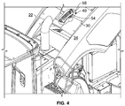
- hood 22 In combination with a pair of opposed pivots 24 and the hood opening device, hood 22 is urged into a rotational movement 26. As further shown in FIG. 1 , hood 22 is in a retracted position, resting on frame 12 which extends to a member such as a counterweight 28. FIG. 2 shows hood 22 in an open position.
- FIG. 2 further shows hood 22 including a metal substructure or metal frame 30.
- Metal frame 30 provides structural strength and stability to the hood to structurally support side panels 34.
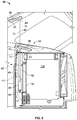
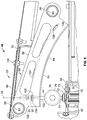
- FIGS. 3-5 show a position control system 40 to raise and lower hood 22.
- Position control system 40 includes a driving device 48 that is drivingly connected to an actuator 42 at one end and is secured by a pin connection 49 to frame structure 51 at the other end of the driving device.
- actuator 42 may be manufactured by Linak (rtm) of Louisville, Kentucky.
- Actuator 42 includes a rod 72 further including a rod adapter, such as a rod eye male adapter 74 having a first end 44 which interacts with a surface 54 associated with hood 22 while the hood is being raised or lowered. It is to be understood that other types and styles of rod adapters may also be used.
- a track 56 includes surface 54.
- Rod adapter 74 and first end 44 are urged into non-rotating movement along an axis 46 by driving device 48.
- rod 72, rod adapter 74 and first end 44 are maintained substantially coincident with axis 46. That is, while rod 72, rod adapter 74 and first end 44 are urged into movement to selectably raise or lower hood 22, the rod, rod adapter and first end are substantially maintained in alignment with axis 46, irrespective of the position of hood 22.
- the position control system may operate within a confined volume 43, which confined volume 43 represents a significantly reduced operating volume when compared to conventional actuator arrangements, permitting room under the hood for other uses.
- such confined volume 43 is centrally positioned about the centreline of the work vehicle and extending substantially vertically in the engine compartment 116, such as between structure defining or surrounding the engine compartment, such as a firewall 112 and cooling component 114 for cooling the fluid.
- FIGS. 6-9 show position control system 40 with hood 22 in a closed position 52 ( FIG. 6 ) and in an open position 50 ( FIG. 8 ).
- actuator 42 is substantially maintained in alignment with axis 46 via a fixed structure, such as a bracket 66 that extends to a flange 68 having an opening 70 through which the actuator extends.
- a non-abrasive retention material 71 such as a bulb seal, is secured along at least a portion of opening 70, and in another embodiment, the bulb seal is secured along the entire opening 70.
- other retention arrangements may be used, such as a clamp or structure extending from the actuator (not shown) that may be directly secured to the frame of the work vehicle.
- confined volume 43 is centrally positioned about the centreline of the work vehicle and extending substantially vertically in engine compartment 116, such as between structure defining or surrounding the engine compartment, such as a firewall 112 and cooling component 114 such as for cooling a fluid.
- confined volume 43 may be located in other positions.
- surface 54 interacts with, i.e. is brought into abutting contact with first end 44, which includes a roller device 76.
- Surface 54 is associated with a track 56 that includes a plate portion 58 having apertures 60 which are configured to receive corresponding rods or pipes 62 to secure the track to hood 22, such as by welding, mechanical fasteners or other suitable device, material or technique.
- a material strip 64 is secured along an edge of plate portion 58, such as by welding, the material strip extending substantially perpendicular to plate portion 58 and including surface 54.
- surface 54 may be directly formed or machined into hood 22.
- track 56 includes a pair of tracks, each including a respective surface 54.
- a pair of plate portions 58 are positioned parallel to each other, with corresponding material strips 64 extending in opposed directions, the material strips each including a corresponding surface 54 with which to interact with roller device 76.
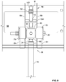
- FIG. 6 further shows positioned between plate portions 58 a slotted alignment plate 104 that include opposed tabs 108 which are received by corresponding slots 106 formed in the plate portions. Alignment plate 104 maintains the relative position and spacing of plate portions 58 with respect to each other.
- slot 110 of alignment plate 104 is configured to permit a threaded rod 102 to move within slot 110, depending upon the amount the hood is opened or closed, due to the path traced during the rotational movement of the hood about its pivot 24 ( FIG. 2 ). As further shown in FIG.
- nuts 91 and 92 may be moved along threaded rod 102 until brought into abutting contact with a surface of alignment plate 104 facing away from rod 72. Nuts 91, 92 may then be brought into contact with each other or jammed together to secure their relative position along threaded rod 102.
- the hood is urged downward and into contact with support structure of the frame of the work vehicle, thereby substantially preventing vibration or "rattling" of the hood when in closed position 52.
- roller device 76 is sufficiently retracted by actuator 42 so that the roller device 76 would no longer be in contact with surface 54 of material strip 64.
- FIG. 7 shows roller device 76 with hood 22 in a closed position (hood 22 and track 56 not shown for reasons of clarity in FIG. 7 ) and FIG. 9 shows roller device 76 with hood 22 in an open position.
- Roller device 76 includes a pair of rollers 75 configured to receive a fastener 82, such as a bolt 84, washers 86 and nuts 88, such as jam nuts.
- a fastener 82 such as a bolt 84
- washers 86 and nuts 88 such as jam nuts.
- guides 78 Positioned beneath the head of fastener 82 and also adjacent to nuts 88 are guides 78 that maintain the rollers in lateral alignment with material strip 64 track 56 by laterally surrounding the material strip 64 of track 56 as shown in FIG. 9 .
- block 80 Positioned between the pair of rollers 75 is a block 80 which is configured to receive bolt 84 and may be fixedly positioned along rod adapter 74 that is secured to the end of rod 72 by nuts 90, such as jam nuts. Further shown in FIG. 9 , block 80 is positioned between the pair of plate portions 58 of the track.
- block 80 is also configured to receive rod adapter 74 and may be fixedly positioned along rod adapter 74 by nuts 90, such as jam nuts.
- nuts 92 such as jam nuts, may be positioned to an opposite portion of block 80 to receive a threaded rod 102 opposite rod adapter 74.
- rod adapter 74 and threaded rod 102 may be parallel to each other.
- rod adapter 74 and threaded rod 102 may be coaxial. As further shown in FIGS.
- adjustment of components such as nuts 91 and flange nuts 92 relating to vertical adjustment of the roller device 76 as previously discussed, as well as other components of the position control system may be achieved through an opening 96 that may be accessed upon the removal of fasteners 100 securing panel 98 to hood 22.
- first end 44 positioned along rod adapter 74 that extends from the end of rod 72 of actuator 42, and including roller device 76 is brought into interaction, i.e. abutting contact, with surface 54 of track 56.
- roller device 76 is brought into abutting contact with surface 54 and urges hood 22, which hood rotates about pivots 24 toward open position 50.
- roller device 76 is lowered, and by force of gravity, similarly supports and permits lowering of the hood 22 toward closed position 52.
- the actuator 42 maintains a position that is substantially coincident with axis 46, which minimizes the amount of space required by the actuator, providing room for other components beneath the hood.
- the roller device may include opposed rollers that are positioned along both sides of the material strip of the track, such that two surfaces may be utilized, and that gravity would not be required to achieve a closed position of the hood or panel. That is, the driving device of the actuator could supply a retraction force that could be utilized to urge the hood or panel toward a closed position.
- the position control system of the present disclosure may be utilized with a hood or panel that does not have a pivot or hinge joint, in which case the first end of the actuator would be directly secured to the hood or panel.
Landscapes
- Superstructure Of Vehicle (AREA)
Claims (11)
- Positionssteuersystem mit:einem Betätigungselement (42), das eine Stange (72) umfasst, mit einem ersten Ende (44), einer Achse (46) und einer Antriebsvorrichtung (48), die ein anderes Ende (49) definiert, das an einer Rahmenstruktur (51) zu befestigen ist, zum Bewegen des ersten Endes des Betätigungselements in entgegengesetzten Richtungen, wobei das erste Ende des Betätigungselements dazu ausgestaltet ist, eine Haube (22) zwischen einer offenen Stellung (Fig. 3) und einer geschlossenen Stellung (Fig. 4) zu bewegen;einer Fläche (54), die der Haube (22) zugeordnet ist und die ausgestaltet ist, um als Reaktion darauf, dass das erste Ende des Betätigungselements die Haube (22) berührt und zwischen der offenen Stellung und der geschlossenen Stellung bewegt, mit dem ersten Ende (44) des Betätigungselements wechselzuwirken, d.h. in aneinander stoßenden Kontakt mit dem ersten Ende gebracht zu werden;wobei das erste Ende (44) des Betätigungselements (42) sich entlang der Achse (46) bewegt und im Wesentlichen zusammenfallend mit der Achse verbleibt, während das erste Ende (44) die Haube zwischen der offenen Stellung und der geschlossenen Stellung bewegt; undwobei die Haubenfläche (54) eine Laufbahn (56) umfasst und das erste Ende (44) eine Rollvorrichtung (76) umfasst, um mit der Laufbahn (56) wechselzuwirken;dadurch gekennzeichnet, dasssich die Stange (72) zu einem Stangenadapter (74), der das erste Ende (44) aufweist, erstreckt, wobei der Stangenadapter von der Antriebsvorrichtung (48) dazu gebracht wird, sich entlang der Achse (46) des Betätigungselements nicht drehbar zu bewegen, wobei das erste Ende des Stangenadapters des Betätigungselements an der Rollvorrichtung (76) befestigt ist, und wobei die Rollvorrichtung (76) ein Paar von Führungen (78) aufweist, die die Laufbahn (56) seitlich umgeben.
- System nach Anspruch 1, dadurch gekennzeichnet, dass die Antriebsvorrichtung (48) elektrisch angetrieben ist.
- System nach Anspruch 1, dadurch gekennzeichnet, dass sich das Betätigungselement (42) durch eine Öffnung (70) erstreckt, die in einer feststehenden Struktur ausgebildet ist, um das Betätigungselement im Wesentlichen zusammenfallend mit der Achse (46) festzuhalten.
- System nach Anspruch 3, dadurch gekennzeichnet, dass wenigstens ein Abschnitt der Öffnung (70) in der feststehenden Struktur eine Wulstdichtung aufweist.
- System nach Anspruch 1, dadurch gekennzeichnet, dass die Rollvorrichtung (76) ein Paar von Rollen (75, 76) umfasst.
- System nach Anspruch 5, dadurch gekennzeichnet, dass die Laufbahn (56) eine getrennte Laufbahn für jede Rolle des Paars von Rollen (75, 76) umfasst.
- System nach Anspruch 6, dadurch gekennzeichnet, dass der Stangenadapter (74) im Wesentlichen zentriert zwischen dem Paar von Rollen (75, 76) angeordnet ist.
- System nach Anspruch 5 oder 6, dadurch gekennzeichnet, dass die Laufbahn (56) eine Ausrichtplatte (104) aufweist, die zwischen den separaten Laufbahnen angeordnet ist.
- Arbeitsfahrzeug (10) mit:einem Motor, der durch Bedienersteuerung mit einer wählbaren Bewegung eines Rahmens (12) verknüpft ist;wobei der Rahmen strukturell eine Kabinenstruktur (20) trägt; undmit einem Hauben-Positionssteuersystem nach einem der vorangehenden Ansprüche, das am Rahmen (12) befestigt ist.
- Arbeitsfahrzeug nach Anspruch 9, dadurch gekennzeichnet, dass das Betätigungselement (42) innerhalb eines Motorraums zwischen einer Struktur, die den Motorraum begrenzt, und einer Kühlkomponente angeordnet ist.
- Arbeitsfahrzeug nach Anspruch 9 oder 10, dadurch gekennzeichnet, dass das System eine Ausrichtplatte (104) mit einer Fläche gegenüberliegend der Haubenfläche (54) zum Öffnen und Schließen der Haube (22) aufweist, wobei die Ausrichtplattenfläche derart gestaltet ist, dass sie mit einer Mutter (92) und einer Gewindestange (102), die sich entgegengesetzt und im Wesentlichen parallel zum Stangenadapter (74) erstreckt, wechselwirkt, um im Wesentlichen eine Vibration der Haube (22) in einer geschlossenen Stellung zu verhindern.
Applications Claiming Priority (1)
| Application Number | Priority Date | Filing Date | Title |
|---|---|---|---|
| US13/050,420 US8499871B2 (en) | 2011-03-17 | 2011-03-17 | Work vehicle hood actuator |
Publications (3)
| Publication Number | Publication Date |
|---|---|
| EP2500497A2 EP2500497A2 (de) | 2012-09-19 |
| EP2500497A3 EP2500497A3 (de) | 2014-06-11 |
| EP2500497B1 true EP2500497B1 (de) | 2017-08-02 |
Family
ID=45894176
Family Applications (1)
| Application Number | Title | Priority Date | Filing Date |
|---|---|---|---|
| EP12159383.4A Active EP2500497B1 (de) | 2011-03-17 | 2012-03-14 | Aktuator für Nutzfahrzeughaube |
Country Status (2)
| Country | Link |
|---|---|
| US (1) | US8499871B2 (de) |
| EP (1) | EP2500497B1 (de) |
Families Citing this family (3)
| Publication number | Priority date | Publication date | Assignee | Title |
|---|---|---|---|---|
| US8573687B2 (en) | 2010-08-27 | 2013-11-05 | L & P Property Management Company | Zero-wall clearance linkage mechanism for providing additional layout |
| KR101709094B1 (ko) * | 2012-10-25 | 2017-02-22 | 볼보 컨스트럭션 이큅먼트 에이비 | 소선회식 건설기계의 후드 개폐장치 |
| US10661839B2 (en) * | 2016-12-05 | 2020-05-26 | Cnh Industrial America Llc | Roller assembly for a hood actuation system |
Family Cites Families (17)
| Publication number | Priority date | Publication date | Assignee | Title |
|---|---|---|---|---|
| US2135613A (en) | 1936-09-30 | 1938-11-08 | Orlow Stephen De | Hood rest for automobiles |
| GB1399612A (en) * | 1973-08-03 | 1975-07-02 | Ford Motor Co | Trucks having cab tilting mechanisms |
| JPS584673A (ja) | 1981-06-30 | 1983-01-11 | Nissan Motor Co Ltd | 開閉体の開閉装置 |
| GB2129379B (en) * | 1982-08-19 | 1986-07-09 | Sanwa Seiki Mfg Co Ltd | Vehicle cab tilting system |
| JPS60183225A (ja) * | 1984-03-01 | 1985-09-18 | Ikuzo Aoki | 凹面カム |
| US4991675A (en) | 1988-10-11 | 1991-02-12 | Navistar International Transportation Corp. | Hood tilt mechanism |
| US5730239A (en) | 1995-10-31 | 1998-03-24 | Freightliner Corporation | Vehicle with torsion bar hood lift assist |
| US6213235B1 (en) * | 1998-10-08 | 2001-04-10 | Case Corporation | Hood lift mechanism |
| US7261286B2 (en) * | 2002-12-11 | 2007-08-28 | Barnes Group Inc. | Two stage hood lift spring assembly |
| US20040262828A1 (en) | 2003-06-24 | 2004-12-30 | Bauman Walter Douglas | Device to provide initial pop-up of an automotive deck lid via a gas spring |
| US6991055B2 (en) | 2003-07-01 | 2006-01-31 | General Motors Corporation | Motorized cover system and method of use thereof |
| JP4306485B2 (ja) | 2004-02-13 | 2009-08-05 | 日産自動車株式会社 | 跳ね上げ式フード |
| CA2524114A1 (en) * | 2004-10-22 | 2006-04-22 | Litens Automotive Partnership | Truck hood actuator |
| JP4601700B2 (ja) | 2008-02-01 | 2010-12-22 | 豊田合成株式会社 | フード跳ね上げ装置 |
| US8100212B2 (en) | 2008-03-24 | 2012-01-24 | Kubota Corporation | Tractor |
| KR100921062B1 (ko) | 2008-05-21 | 2009-10-08 | 현대자동차주식회사 | 액티브 후드 시스템의 리프트 장치 |
| JP4514813B2 (ja) | 2008-06-04 | 2010-07-28 | 太平洋工業株式会社 | ボンネット衝撃吸収装置 |
-
2011
- 2011-03-17 US US13/050,420 patent/US8499871B2/en not_active Expired - Fee Related
-
2012
- 2012-03-14 EP EP12159383.4A patent/EP2500497B1/de active Active
Non-Patent Citations (1)
| Title |
|---|
| None * |
Also Published As
| Publication number | Publication date |
|---|---|
| US8499871B2 (en) | 2013-08-06 |
| EP2500497A2 (de) | 2012-09-19 |
| EP2500497A3 (de) | 2014-06-11 |
| US20120235446A1 (en) | 2012-09-20 |
Similar Documents
| Publication | Publication Date | Title |
|---|---|---|
| EP2326466B1 (de) | Luftkissenplattform zum tragen eines manipulatorarms und verfahrbarer roboter | |
| KR101048145B1 (ko) | 도어용 그리퍼 | |
| EP2213408B1 (de) | Schraubenanzugsvorrichtung | |
| EP2500497B1 (de) | Aktuator für Nutzfahrzeughaube | |
| US8800705B2 (en) | Roll-out cab for off-road equipment | |
| US10899404B2 (en) | Door hoist apparatuses including multi-bar actuation assemblies with suction end effectors and methods using the same | |
| WO2013145360A1 (ja) | ブルドーザ | |
| WO2015078810A1 (en) | Traveling device and working machine | |
| EP2500243B1 (de) | Schwingungsdämpfervorrichtung | |
| JP6829635B2 (ja) | バッテリ取付構造 | |
| US10583866B2 (en) | Work vehicle | |
| US6848525B1 (en) | Lift for vehicle hoods and the like | |
| US11305394B2 (en) | Blade guard for saw of saw house and method | |
| CN214684932U (zh) | 箱形钢结构翻转工装 | |
| CA2373692A1 (en) | Simplified multi axis, lightweight, steerable power drive unit, for handling aircraft cargo | |
| EP3090928B1 (de) | Kabine für ein fahrzeug, insbesondere für einen landwirtschaftlichen traktor | |
| CN210713028U (zh) | 新型装载机驾驶室 | |
| CN218715200U (zh) | 一种覆盖件结构及泵车 | |
| JP6302389B2 (ja) | キャビン及び作業機 | |
| US12312768B2 (en) | Removable cab toe box for a work machine | |
| CN218226664U (zh) | 一种协作机器人 | |
| JP6300696B2 (ja) | 作業機のキャビン及びこのキャビンを備えた作業機 | |
| CN118809528A (zh) | 一种塞拉门拆装工装 | |
| JP2010047224A (ja) | 車両用キャビンドア開閉装置 | |
| CN119703528A (zh) | 一种小型协助平台式焊接工作站 |
Legal Events
| Date | Code | Title | Description |
|---|---|---|---|
| PUAI | Public reference made under article 153(3) epc to a published international application that has entered the european phase |
Free format text: ORIGINAL CODE: 0009012 |
|
| AK | Designated contracting states |
Kind code of ref document: A2 Designated state(s): AL AT BE BG CH CY CZ DE DK EE ES FI FR GB GR HR HU IE IS IT LI LT LU LV MC MK MT NL NO PL PT RO RS SE SI SK SM TR |
|
| AX | Request for extension of the european patent |
Extension state: BA ME |
|
| PUAL | Search report despatched |
Free format text: ORIGINAL CODE: 0009013 |
|
| RAP1 | Party data changed (applicant data changed or rights of an application transferred) |
Owner name: CNH INDUSTRIAL ITALIA S.P.A. |
|
| AK | Designated contracting states |
Kind code of ref document: A3 Designated state(s): AL AT BE BG CH CY CZ DE DK EE ES FI FR GB GR HR HU IE IS IT LI LT LU LV MC MK MT NL NO PL PT RO RS SE SI SK SM TR |
|
| AX | Request for extension of the european patent |
Extension state: BA ME |
|
| RIC1 | Information provided on ipc code assigned before grant |
Ipc: B62D 25/12 20060101ALI20140508BHEP Ipc: B62D 33/067 20060101ALI20140508BHEP Ipc: E05F 1/10 20060101AFI20140508BHEP Ipc: E05F 15/12 20060101ALI20140508BHEP |
|
| 17P | Request for examination filed |
Effective date: 20141211 |
|
| RBV | Designated contracting states (corrected) |
Designated state(s): AL AT BE BG CH CY CZ DE DK EE ES FI FR GB GR HR HU IE IS IT LI LT LU LV MC MK MT NL NO PL PT RO RS SE SI SK SM TR |
|
| REG | Reference to a national code |
Ref country code: DE Ref legal event code: R079 Ref document number: 602012035218 Country of ref document: DE Free format text: PREVIOUS MAIN CLASS: E05F0001100000 Ipc: E05F0015530000 |
|
| GRAP | Despatch of communication of intention to grant a patent |
Free format text: ORIGINAL CODE: EPIDOSNIGR1 |
|
| RIC1 | Information provided on ipc code assigned before grant |
Ipc: E05F 1/10 20060101ALI20170223BHEP Ipc: E05F 15/611 20150101ALI20170223BHEP Ipc: E05F 15/53 20150101AFI20170223BHEP |
|
| INTG | Intention to grant announced |
Effective date: 20170323 |
|
| GRAS | Grant fee paid |
Free format text: ORIGINAL CODE: EPIDOSNIGR3 |
|
| GRAA | (expected) grant |
Free format text: ORIGINAL CODE: 0009210 |
|
| AK | Designated contracting states |
Kind code of ref document: B1 Designated state(s): AL AT BE BG CH CY CZ DE DK EE ES FI FR GB GR HR HU IE IS IT LI LT LU LV MC MK MT NL NO PL PT RO RS SE SI SK SM TR |
|
| REG | Reference to a national code |
Ref country code: GB Ref legal event code: FG4D |
|
| REG | Reference to a national code |
Ref country code: CH Ref legal event code: EP Ref country code: AT Ref legal event code: REF Ref document number: 914669 Country of ref document: AT Kind code of ref document: T Effective date: 20170815 |
|
| REG | Reference to a national code |
Ref country code: IE Ref legal event code: FG4D |
|
| REG | Reference to a national code |
Ref country code: DE Ref legal event code: R096 Ref document number: 602012035218 Country of ref document: DE |
|
| REG | Reference to a national code |
Ref country code: NL Ref legal event code: MP Effective date: 20170802 |
|
| REG | Reference to a national code |
Ref country code: AT Ref legal event code: MK05 Ref document number: 914669 Country of ref document: AT Kind code of ref document: T Effective date: 20170802 |
|
| REG | Reference to a national code |
Ref country code: LT Ref legal event code: MG4D |
|
| REG | Reference to a national code |
Ref country code: FR Ref legal event code: PLFP Year of fee payment: 7 |
|
| PG25 | Lapsed in a contracting state [announced via postgrant information from national office to epo] |
Ref country code: LT Free format text: LAPSE BECAUSE OF FAILURE TO SUBMIT A TRANSLATION OF THE DESCRIPTION OR TO PAY THE FEE WITHIN THE PRESCRIBED TIME-LIMIT Effective date: 20170802 Ref country code: NO Free format text: LAPSE BECAUSE OF FAILURE TO SUBMIT A TRANSLATION OF THE DESCRIPTION OR TO PAY THE FEE WITHIN THE PRESCRIBED TIME-LIMIT Effective date: 20171102 Ref country code: NL Free format text: LAPSE BECAUSE OF FAILURE TO SUBMIT A TRANSLATION OF THE DESCRIPTION OR TO PAY THE FEE WITHIN THE PRESCRIBED TIME-LIMIT Effective date: 20170802 Ref country code: FI Free format text: LAPSE BECAUSE OF FAILURE TO SUBMIT A TRANSLATION OF THE DESCRIPTION OR TO PAY THE FEE WITHIN THE PRESCRIBED TIME-LIMIT Effective date: 20170802 Ref country code: HR Free format text: LAPSE BECAUSE OF FAILURE TO SUBMIT A TRANSLATION OF THE DESCRIPTION OR TO PAY THE FEE WITHIN THE PRESCRIBED TIME-LIMIT Effective date: 20170802 Ref country code: AT Free format text: LAPSE BECAUSE OF FAILURE TO SUBMIT A TRANSLATION OF THE DESCRIPTION OR TO PAY THE FEE WITHIN THE PRESCRIBED TIME-LIMIT Effective date: 20170802 Ref country code: SE Free format text: LAPSE BECAUSE OF FAILURE TO SUBMIT A TRANSLATION OF THE DESCRIPTION OR TO PAY THE FEE WITHIN THE PRESCRIBED TIME-LIMIT Effective date: 20170802 |
|
| PG25 | Lapsed in a contracting state [announced via postgrant information from national office to epo] |
Ref country code: PL Free format text: LAPSE BECAUSE OF FAILURE TO SUBMIT A TRANSLATION OF THE DESCRIPTION OR TO PAY THE FEE WITHIN THE PRESCRIBED TIME-LIMIT Effective date: 20170802 Ref country code: IS Free format text: LAPSE BECAUSE OF FAILURE TO SUBMIT A TRANSLATION OF THE DESCRIPTION OR TO PAY THE FEE WITHIN THE PRESCRIBED TIME-LIMIT Effective date: 20171202 Ref country code: RS Free format text: LAPSE BECAUSE OF FAILURE TO SUBMIT A TRANSLATION OF THE DESCRIPTION OR TO PAY THE FEE WITHIN THE PRESCRIBED TIME-LIMIT Effective date: 20170802 Ref country code: ES Free format text: LAPSE BECAUSE OF FAILURE TO SUBMIT A TRANSLATION OF THE DESCRIPTION OR TO PAY THE FEE WITHIN THE PRESCRIBED TIME-LIMIT Effective date: 20170802 Ref country code: GR Free format text: LAPSE BECAUSE OF FAILURE TO SUBMIT A TRANSLATION OF THE DESCRIPTION OR TO PAY THE FEE WITHIN THE PRESCRIBED TIME-LIMIT Effective date: 20171103 Ref country code: BG Free format text: LAPSE BECAUSE OF FAILURE TO SUBMIT A TRANSLATION OF THE DESCRIPTION OR TO PAY THE FEE WITHIN THE PRESCRIBED TIME-LIMIT Effective date: 20171102 Ref country code: LV Free format text: LAPSE BECAUSE OF FAILURE TO SUBMIT A TRANSLATION OF THE DESCRIPTION OR TO PAY THE FEE WITHIN THE PRESCRIBED TIME-LIMIT Effective date: 20170802 |
|
| PG25 | Lapsed in a contracting state [announced via postgrant information from national office to epo] |
Ref country code: RO Free format text: LAPSE BECAUSE OF FAILURE TO SUBMIT A TRANSLATION OF THE DESCRIPTION OR TO PAY THE FEE WITHIN THE PRESCRIBED TIME-LIMIT Effective date: 20170802 Ref country code: CZ Free format text: LAPSE BECAUSE OF FAILURE TO SUBMIT A TRANSLATION OF THE DESCRIPTION OR TO PAY THE FEE WITHIN THE PRESCRIBED TIME-LIMIT Effective date: 20170802 Ref country code: DK Free format text: LAPSE BECAUSE OF FAILURE TO SUBMIT A TRANSLATION OF THE DESCRIPTION OR TO PAY THE FEE WITHIN THE PRESCRIBED TIME-LIMIT Effective date: 20170802 |
|
| REG | Reference to a national code |
Ref country code: DE Ref legal event code: R097 Ref document number: 602012035218 Country of ref document: DE |
|
| PG25 | Lapsed in a contracting state [announced via postgrant information from national office to epo] |
Ref country code: EE Free format text: LAPSE BECAUSE OF FAILURE TO SUBMIT A TRANSLATION OF THE DESCRIPTION OR TO PAY THE FEE WITHIN THE PRESCRIBED TIME-LIMIT Effective date: 20170802 Ref country code: SM Free format text: LAPSE BECAUSE OF FAILURE TO SUBMIT A TRANSLATION OF THE DESCRIPTION OR TO PAY THE FEE WITHIN THE PRESCRIBED TIME-LIMIT Effective date: 20170802 Ref country code: SK Free format text: LAPSE BECAUSE OF FAILURE TO SUBMIT A TRANSLATION OF THE DESCRIPTION OR TO PAY THE FEE WITHIN THE PRESCRIBED TIME-LIMIT Effective date: 20170802 |
|
| PLBE | No opposition filed within time limit |
Free format text: ORIGINAL CODE: 0009261 |
|
| STAA | Information on the status of an ep patent application or granted ep patent |
Free format text: STATUS: NO OPPOSITION FILED WITHIN TIME LIMIT |
|
| 26N | No opposition filed |
Effective date: 20180503 |
|
| PG25 | Lapsed in a contracting state [announced via postgrant information from national office to epo] |
Ref country code: SI Free format text: LAPSE BECAUSE OF FAILURE TO SUBMIT A TRANSLATION OF THE DESCRIPTION OR TO PAY THE FEE WITHIN THE PRESCRIBED TIME-LIMIT Effective date: 20170802 |
|
| REG | Reference to a national code |
Ref country code: CH Ref legal event code: PL |
|
| PG25 | Lapsed in a contracting state [announced via postgrant information from national office to epo] |
Ref country code: MC Free format text: LAPSE BECAUSE OF FAILURE TO SUBMIT A TRANSLATION OF THE DESCRIPTION OR TO PAY THE FEE WITHIN THE PRESCRIBED TIME-LIMIT Effective date: 20170802 |
|
| REG | Reference to a national code |
Ref country code: BE Ref legal event code: MM Effective date: 20180331 |
|
| REG | Reference to a national code |
Ref country code: IE Ref legal event code: MM4A |
|
| PG25 | Lapsed in a contracting state [announced via postgrant information from national office to epo] |
Ref country code: LU Free format text: LAPSE BECAUSE OF NON-PAYMENT OF DUE FEES Effective date: 20180314 |
|
| PG25 | Lapsed in a contracting state [announced via postgrant information from national office to epo] |
Ref country code: IE Free format text: LAPSE BECAUSE OF NON-PAYMENT OF DUE FEES Effective date: 20180314 |
|
| PG25 | Lapsed in a contracting state [announced via postgrant information from national office to epo] |
Ref country code: BE Free format text: LAPSE BECAUSE OF NON-PAYMENT OF DUE FEES Effective date: 20180331 Ref country code: LI Free format text: LAPSE BECAUSE OF NON-PAYMENT OF DUE FEES Effective date: 20180331 Ref country code: CH Free format text: LAPSE BECAUSE OF NON-PAYMENT OF DUE FEES Effective date: 20180331 |
|
| PG25 | Lapsed in a contracting state [announced via postgrant information from national office to epo] |
Ref country code: MT Free format text: LAPSE BECAUSE OF NON-PAYMENT OF DUE FEES Effective date: 20180314 |
|
| PG25 | Lapsed in a contracting state [announced via postgrant information from national office to epo] |
Ref country code: TR Free format text: LAPSE BECAUSE OF FAILURE TO SUBMIT A TRANSLATION OF THE DESCRIPTION OR TO PAY THE FEE WITHIN THE PRESCRIBED TIME-LIMIT Effective date: 20170802 |
|
| PG25 | Lapsed in a contracting state [announced via postgrant information from national office to epo] |
Ref country code: PT Free format text: LAPSE BECAUSE OF FAILURE TO SUBMIT A TRANSLATION OF THE DESCRIPTION OR TO PAY THE FEE WITHIN THE PRESCRIBED TIME-LIMIT Effective date: 20170802 Ref country code: HU Free format text: LAPSE BECAUSE OF FAILURE TO SUBMIT A TRANSLATION OF THE DESCRIPTION OR TO PAY THE FEE WITHIN THE PRESCRIBED TIME-LIMIT; INVALID AB INITIO Effective date: 20120314 |
|
| PG25 | Lapsed in a contracting state [announced via postgrant information from national office to epo] |
Ref country code: CY Free format text: LAPSE BECAUSE OF FAILURE TO SUBMIT A TRANSLATION OF THE DESCRIPTION OR TO PAY THE FEE WITHIN THE PRESCRIBED TIME-LIMIT Effective date: 20170802 Ref country code: MK Free format text: LAPSE BECAUSE OF NON-PAYMENT OF DUE FEES Effective date: 20170802 |
|
| PG25 | Lapsed in a contracting state [announced via postgrant information from national office to epo] |
Ref country code: AL Free format text: LAPSE BECAUSE OF FAILURE TO SUBMIT A TRANSLATION OF THE DESCRIPTION OR TO PAY THE FEE WITHIN THE PRESCRIBED TIME-LIMIT Effective date: 20170802 |
|
| REG | Reference to a national code |
Ref country code: DE Ref legal event code: R082 Ref document number: 602012035218 Country of ref document: DE Representative=s name: KROHER STROBEL RECHTS- UND PATENTANWAELTE PART, DE |
|
| PGFP | Annual fee paid to national office [announced via postgrant information from national office to epo] |
Ref country code: GB Payment date: 20260319 Year of fee payment: 15 |
|
| PGFP | Annual fee paid to national office [announced via postgrant information from national office to epo] |
Ref country code: DE Payment date: 20260320 Year of fee payment: 15 |
|
| PGFP | Annual fee paid to national office [announced via postgrant information from national office to epo] |
Ref country code: IT Payment date: 20260320 Year of fee payment: 15 |
|
| PGFP | Annual fee paid to national office [announced via postgrant information from national office to epo] |
Ref country code: FR Payment date: 20260323 Year of fee payment: 15 |