EP2500501A2 - Agencement de cadre doté d'au moins un élément de raccordement de cadre - Google Patents
Agencement de cadre doté d'au moins un élément de raccordement de cadre Download PDFInfo
- Publication number
- EP2500501A2 EP2500501A2 EP12001332A EP12001332A EP2500501A2 EP 2500501 A2 EP2500501 A2 EP 2500501A2 EP 12001332 A EP12001332 A EP 12001332A EP 12001332 A EP12001332 A EP 12001332A EP 2500501 A2 EP2500501 A2 EP 2500501A2
- Authority
- EP
- European Patent Office
- Prior art keywords
- type
- frame
- frame connection
- joining element
- joining
- Prior art date
- Legal status (The legal status is an assumption and is not a legal conclusion. Google has not performed a legal analysis and makes no representation as to the accuracy of the status listed.)
- Withdrawn
Links
- 238000009413 insulation Methods 0.000 abstract description 2
- 239000002131 composite material Substances 0.000 abstract 1
- 238000000465 moulding Methods 0.000 description 2
- 238000003801 milling Methods 0.000 description 1
- 230000003287 optical effect Effects 0.000 description 1
- 230000035939 shock Effects 0.000 description 1
Images

Classifications
-
- E—FIXED CONSTRUCTIONS
- E06—DOORS, WINDOWS, SHUTTERS, OR ROLLER BLINDS IN GENERAL; LADDERS
- E06B—FIXED OR MOVABLE CLOSURES FOR OPENINGS IN BUILDINGS, VEHICLES, FENCES OR LIKE ENCLOSURES IN GENERAL, e.g. DOORS, WINDOWS, BLINDS, GATES
- E06B1/00—Border constructions of openings in walls, floors, or ceilings; Frames to be rigidly mounted in such openings
- E06B1/62—Tightening or covering joints between the border of openings and the frame or between contiguous frames
- E06B1/68—Tightening or covering joints between the border of openings and the frame or between contiguous frames by profiled external parts
-
- E—FIXED CONSTRUCTIONS
- E06—DOORS, WINDOWS, SHUTTERS, OR ROLLER BLINDS IN GENERAL; LADDERS
- E06B—FIXED OR MOVABLE CLOSURES FOR OPENINGS IN BUILDINGS, VEHICLES, FENCES OR LIKE ENCLOSURES IN GENERAL, e.g. DOORS, WINDOWS, BLINDS, GATES
- E06B1/00—Border constructions of openings in walls, floors, or ceilings; Frames to be rigidly mounted in such openings
- E06B1/02—Base frames, i.e. template frames for openings in walls or the like, provided with means for securing a further rigidly-mounted frame; Special adaptations of frames to be fixed therein
Definitions
- the present invention relates to a frame connection element according to the preamble of claim 1.
- Frame connection elements are used, for example, for widening window or door frames in order to adapt a given window or a given door to a predetermined wall opening.
- the frame connection elements are usually connected to the profile of a window frame. If the wall opening is comparatively large in comparison to a door to be installed or a window to be installed, there may be a need for several frame connection elements to be connected to one another.
- connection brackets are used to connect the frame connection elements with each other or with the profile of a window or door frame so far. Since this connection clip is detachably connected to a frame connection element, there is a risk that such a connection clip is lost.
- a frame connection element comprising a sandwich plate with two parallel spaced plastic plates and an insulating layer which is provided between the two spaced plastic plates, and a connecting means in that an integrally formed with a plastic plate connecting means is provided on at least one end face of at least one plastic plate and the connecting means is a joining element of the first kind for forming a snap connection with a joining element of the second kind.
- the joining element of the first type and / or the joining element of the second type are pin-shaped in cross-section.
- the joining element of the first type and the joining element of the second type may have an undercut and a snap hook.
- the joining element of the first type and / or the joining element of the second type are / is formed like a rail.
- the joining element of the first type forms an extension of the inner side surface of the at least one plastic plate.
- the joining element can be easily produced, for example by subsequent milling on an already manufactured sandwich panel.
- a cover element in particular a covering element made of plastic, is provided at least in sections on at least one end face of the sandwich panel.
- the cover serves to protect, for example, the insulation layer from external influences such as moisture or shock.
- the at least one plastic plate has a joining element of the first type on one end side and a joining element of the second type on the opposite end side, wherein the joining element of the second type is formed integrally with the plastic plate.
- the at least one plastic plate has a joining element of the first type on both end faces.
- This embodiment is particularly suitable for the use of a frame connection element between two profile strips of a door or window frame.
- the outer sides of the two frame connection elements or the frame connection element and the profile strip form a flat surface in the region of the snap connection.
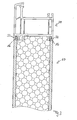
- a first embodiment of a frame assembly 10 is shown.
- the frame assembly comprises two parallel spaced plastic plates 12a and 12b. Between these two plastic plates 12a and 12b, an insulating layer 14 is arranged, so that the plastic plates 12a, 12b and the insulating layer 14 result in a sandwich plate.
- a connecting element 16 which is pin-shaped in cross section is provided, which is formed integrally with the corresponding plastic plate 12a, 12b.
- the connecting means 16 is a joining element of the first type for forming a snap connection with a joining element, not shown, of the second type.
- the joining element 16 has an undercut 18 and a snap hook 19. In the undercut 18, for example, a snap hook of a second joining element can be inserted. At the in Fig. 1 illustrated embodiment, a joining element of the first type 16 is provided on each end face.
- FIG. 2 shown frame connection element 100 differs from that in Fig. 1 shown frame connection element 10 characterized in that at one end face of a plastic plate 112a, 112b, a joining element of the first type 16 and on the opposite end face a joining element of the second type 20 are arranged. Both the joining element of the first type 16 and the wing element of the second type 20 are integrally formed with the plastic plates 112a and 112b.
- the joining element of the second type 20 comprises an undercut 22 and a snap hook 24. It is designed to form a snap connection with the joining element 16 of the first type.
- the joining element of the second type 20 is designed as an extension of the plastic plate 112a or 112b so that the outside of the joining element of the second type 20 and the outside of the plastic plate 112a or 112b forms a flat surface.
- the joining elements of the first type 16 and the second type 20 are essentially contoured and dimensioned such that when forming the snap connection between the joining element 16 of the first type 16 and the joining element of the second type 20, the outer sides of the plastic plates 112a and 112b to be joined form a flat surface.
- a joining element of the first type is arranged, is particularly suitable for use between two moldings of a window or door, as the moldings of two windows or doors usually a given shape exhibit. While the in Fig. 2 embodiment shown is particularly suitable to connect frame connection parts together.
- a frame connection element 10 is shown in conjunction with a profile strip 30 of a window or door frame.
- the profile strip has two joining elements of the second type 32, which form a snap connection with the joining elements of the first type 16 of the frame connection element 10.
- the plastic plate preferably has a thickness of about 3 to 6 mm.
- the illustrated joining elements of the first and second types 16, 20 and 32 are rail-like, in order to produce a stable connection between the two interconnected connection elements or between the connection element 10 and the profile strip 30.
Landscapes
- Engineering & Computer Science (AREA)
- Civil Engineering (AREA)
- Structural Engineering (AREA)
- Connection Of Plates (AREA)
- Joining Of Corner Units Of Frames Or Wings (AREA)
- Connector Housings Or Holding Contact Members (AREA)
Applications Claiming Priority (1)
| Application Number | Priority Date | Filing Date | Title |
|---|---|---|---|
| DE202011004097U DE202011004097U1 (de) | 2011-03-17 | 2011-03-17 | Rahmenanordnung mit wenigstens einem Rahmenanschlusselement |
Publications (2)
| Publication Number | Publication Date |
|---|---|
| EP2500501A2 true EP2500501A2 (fr) | 2012-09-19 |
| EP2500501A3 EP2500501A3 (fr) | 2014-06-11 |
Family
ID=44586378
Family Applications (1)
| Application Number | Title | Priority Date | Filing Date |
|---|---|---|---|
| EP12001332.1A Withdrawn EP2500501A3 (fr) | 2011-03-17 | 2012-02-29 | Agencement de cadre doté d'au moins un élément de raccordement de cadre |
Country Status (2)
| Country | Link |
|---|---|
| EP (1) | EP2500501A3 (fr) |
| DE (1) | DE202011004097U1 (fr) |
Families Citing this family (3)
| Publication number | Priority date | Publication date | Assignee | Title |
|---|---|---|---|---|
| AT13080U1 (de) * | 2012-01-11 | 2013-05-15 | Frinorm Ag | Rahmenverbreiterung |
| DE202012001582U1 (de) | 2012-02-17 | 2012-04-17 | Sls Kunststoffverarbeitungs Gmbh & Co. Kg | Rahmenanschlusselement |
| DE102021114500A1 (de) | 2021-06-07 | 2022-12-08 | Profine Gmbh | Zweiteiliges Bodenanschlussprofil |
Family Cites Families (3)
| Publication number | Priority date | Publication date | Assignee | Title |
|---|---|---|---|---|
| CO4870729A1 (es) * | 1998-02-09 | 1999-12-27 | Steven C Meyerson | Paneles de construccion |
| CH694435A5 (de) * | 2000-05-16 | 2005-01-14 | Dfs Technology & Service Ag | Rahmenverbreiterung für ein Fenster oder eine Tür sowie Fenster oder Tür mit dieser Rahmenverbreiterung. |
| DE202010001398U1 (de) * | 2010-01-27 | 2010-05-27 | Beck, Walter, Dipl.-Ing. | Profilsystem |
-
2011
- 2011-03-17 DE DE202011004097U patent/DE202011004097U1/de not_active Expired - Lifetime
-
2012
- 2012-02-29 EP EP12001332.1A patent/EP2500501A3/fr not_active Withdrawn
Non-Patent Citations (1)
| Title |
|---|
| None |
Also Published As
| Publication number | Publication date |
|---|---|
| DE202011004097U1 (de) | 2011-08-08 |
| EP2500501A3 (fr) | 2014-06-11 |
Similar Documents
| Publication | Publication Date | Title |
|---|---|---|
| EP1555376A1 (fr) | Profilé composite | |
| EP2581537B1 (fr) | Élément de fenêtre ou de porte | |
| DE202013103100U1 (de) | Flächenelement einer Brandschutzverglasung, insbesondere Glastür für Brandschutzzwecke zur Vermeidung des Durchtritts von Feuer und Rauch im Brandfall von einem Raum in einen anderen | |
| DE102006059854A1 (de) | Armiertes Kunststoffprofil für Fenster-, Türen- und Fassadenelemente | |
| EP2666948A1 (fr) | Agencement de cadre pour un panneau de porte sectionnelle | |
| EP2003280B1 (fr) | Vantail, de préférence pour une porte d'entrée de maison | |
| EP2500501A2 (fr) | Agencement de cadre doté d'au moins un élément de raccordement de cadre | |
| EP2803807B1 (fr) | Porte | |
| EP2762668B1 (fr) | Profil de raccordement | |
| DE202016101078U1 (de) | Geländer | |
| DE202016101405U1 (de) | Kastenfenster für ein Gebäude und Kastenrahmen | |
| DE102008020988A1 (de) | Wärmeisolierendes Rahmenprofil für die Herstellung von Tür- und Fensterrahmen | |
| DE102013112435A1 (de) | Verbundprofil und Verfahren zum Herstellen eines Verbundprofils | |
| EP2593319B1 (fr) | Vitre de fenêtre et procédé pour monter une vitre de fenêtre sur un véhicule | |
| DE102011008765A1 (de) | Profilanordnung, Rahmen und Rahmenanordnung | |
| DE202013100101U1 (de) | Wärmedämmleiste und Rahmenprofil für ein Fenster, eine Tür, eine Fassade oder ein Lichtdach | |
| DE20100618U1 (de) | Rahmenprofil | |
| DE202005007415U1 (de) | Fenstersprosse für Isolierglaseinheiten | |
| EP3574176B1 (fr) | Rail de guidage pour volets roulants, ecrans de protection solaire ou similaire, et procede de fabrication associe | |
| EP4424968B1 (fr) | Profilé composite, cadre et procédé de fabrication du profilé composite | |
| EP1681430A2 (fr) | Profilé composite pour cadres d'éléments de paroi, portes et fenêtres | |
| CH704434B1 (de) | Dämmelement zur Rahmenverbreiterung. | |
| DE102014112092A1 (de) | Tür, Fenster oder Fassadenelement mit einem Eckverbinder | |
| DE202012003181U1 (de) | Tür-oder Fensterprofil | |
| WO1990002237A1 (fr) | Ventail de fenetre ou de porte |
Legal Events
| Date | Code | Title | Description |
|---|---|---|---|
| PUAI | Public reference made under article 153(3) epc to a published international application that has entered the european phase |
Free format text: ORIGINAL CODE: 0009012 |
|
| AK | Designated contracting states |
Kind code of ref document: A2 Designated state(s): AL AT BE BG CH CY CZ DE DK EE ES FI FR GB GR HR HU IE IS IT LI LT LU LV MC MK MT NL NO PL PT RO RS SE SI SK SM TR |
|
| AX | Request for extension of the european patent |
Extension state: BA ME |
|
| PUAL | Search report despatched |
Free format text: ORIGINAL CODE: 0009013 |
|
| AK | Designated contracting states |
Kind code of ref document: A3 Designated state(s): AL AT BE BG CH CY CZ DE DK EE ES FI FR GB GR HR HU IE IS IT LI LT LU LV MC MK MT NL NO PL PT RO RS SE SI SK SM TR |
|
| AX | Request for extension of the european patent |
Extension state: BA ME |
|
| RIC1 | Information provided on ipc code assigned before grant |
Ipc: E06B 1/02 20060101ALI20140508BHEP Ipc: E06B 1/62 20060101AFI20140508BHEP |
|
| STAA | Information on the status of an ep patent application or granted ep patent |
Free format text: STATUS: THE APPLICATION IS DEEMED TO BE WITHDRAWN |
|
| 18D | Application deemed to be withdrawn |
Effective date: 20141212 |