EP2500502A2 - Kit de fabrication d'un rebord de fenêtre - Google Patents
Kit de fabrication d'un rebord de fenêtre Download PDFInfo
- Publication number
- EP2500502A2 EP2500502A2 EP12159449A EP12159449A EP2500502A2 EP 2500502 A2 EP2500502 A2 EP 2500502A2 EP 12159449 A EP12159449 A EP 12159449A EP 12159449 A EP12159449 A EP 12159449A EP 2500502 A2 EP2500502 A2 EP 2500502A2
- Authority
- EP
- European Patent Office
- Prior art keywords
- window
- guide element
- kit
- window sill
- sill
- Prior art date
- Legal status (The legal status is an assumption and is not a legal conclusion. Google has not performed a legal analysis and makes no representation as to the accuracy of the status listed.)
- Withdrawn
Links
- 238000010276 construction Methods 0.000 title description 2
- 239000011505 plaster Substances 0.000 claims abstract description 13
- 238000010422 painting Methods 0.000 claims abstract description 9
- 238000000034 method Methods 0.000 claims abstract description 8
- 229920001296 polysiloxane Polymers 0.000 claims abstract description 3
- 239000004575 stone Substances 0.000 claims abstract description 3
- 239000012720 thermal barrier coating Substances 0.000 claims description 5
- 229910052751 metal Inorganic materials 0.000 claims description 3
- 239000002184 metal Substances 0.000 claims description 3
- 238000007789 sealing Methods 0.000 claims description 3
- 239000000853 adhesive Substances 0.000 claims description 2
- 230000001070 adhesive effect Effects 0.000 claims description 2
- 238000003780 insertion Methods 0.000 claims description 2
- 230000037431 insertion Effects 0.000 claims description 2
- 238000009413 insulation Methods 0.000 claims description 2
- 230000003014 reinforcing effect Effects 0.000 claims description 2
- 238000004140 cleaning Methods 0.000 description 4
- 238000004519 manufacturing process Methods 0.000 description 2
- 238000004026 adhesive bonding Methods 0.000 description 1
- 239000002313 adhesive film Substances 0.000 description 1
- 229910052782 aluminium Inorganic materials 0.000 description 1
- XAGFODPZIPBFFR-UHFFFAOYSA-N aluminium Chemical compound [Al] XAGFODPZIPBFFR-UHFFFAOYSA-N 0.000 description 1
- 239000002969 artificial stone Substances 0.000 description 1
- 238000011109 contamination Methods 0.000 description 1
- 238000005336 cracking Methods 0.000 description 1
- 239000011888 foil Substances 0.000 description 1
- 239000011810 insulating material Substances 0.000 description 1
- 239000000463 material Substances 0.000 description 1
- 230000005855 radiation Effects 0.000 description 1
Images



Classifications
-
- E—FIXED CONSTRUCTIONS
- E06—DOORS, WINDOWS, SHUTTERS, OR ROLLER BLINDS IN GENERAL; LADDERS
- E06B—FIXED OR MOVABLE CLOSURES FOR OPENINGS IN BUILDINGS, VEHICLES, FENCES OR LIKE ENCLOSURES IN GENERAL, e.g. DOORS, WINDOWS, BLINDS, GATES
- E06B1/00—Border constructions of openings in walls, floors, or ceilings; Frames to be rigidly mounted in such openings
- E06B1/70—Sills; Thresholds
- E06B1/702—Window sills
- E06B1/705—End-caps therefor
-
- E—FIXED CONSTRUCTIONS
- E06—DOORS, WINDOWS, SHUTTERS, OR ROLLER BLINDS IN GENERAL; LADDERS
- E06B—FIXED OR MOVABLE CLOSURES FOR OPENINGS IN BUILDINGS, VEHICLES, FENCES OR LIKE ENCLOSURES IN GENERAL, e.g. DOORS, WINDOWS, BLINDS, GATES
- E06B1/00—Border constructions of openings in walls, floors, or ceilings; Frames to be rigidly mounted in such openings
- E06B1/62—Tightening or covering joints between the border of openings and the frame or between contiguous frames
- E06B1/68—Tightening or covering joints between the border of openings and the frame or between contiguous frames by profiled external parts
-
- E—FIXED CONSTRUCTIONS
- E06—DOORS, WINDOWS, SHUTTERS, OR ROLLER BLINDS IN GENERAL; LADDERS
- E06B—FIXED OR MOVABLE CLOSURES FOR OPENINGS IN BUILDINGS, VEHICLES, FENCES OR LIKE ENCLOSURES IN GENERAL, e.g. DOORS, WINDOWS, BLINDS, GATES
- E06B1/00—Border constructions of openings in walls, floors, or ceilings; Frames to be rigidly mounted in such openings
- E06B1/70—Sills; Thresholds
- E06B1/702—Window sills
Definitions
- the invention relates to a kit for producing a window sill following the window frame of a window, which is arranged in a window opening, for example a wall, with a thermal barrier coating and at least one plaster layer, and a method for assembling such a sill.
- Window sills are usually cut to the size of the shell of the respective window opening and then added to the window sill, with an attachment to the window sash or in the masonry of the window opening.
- the sill for example made of natural or artificial stone is usually provided with a cover, so that dirt in the subsequent plastering and painting work can be removed by peeling off the film.
- an additional work step is necessary for this, with the adhesive films being able to be removed with a longer residence time due to the influence of the UV radiation of the sunlight usually only with great effort.
- the cleaning effort in window sills from mostly multi-angled metal profiles is also very expensive.
- a sill known which consists of a substantially Z-shaped folded profile having a retaining leg for attachment to the window sill, a sloping outwardly sloping base leg and a drip at the front edge.
- attachable end profiles are provided, the sill is used for mounting with the attached end profiles between the reveal walls of the window opening.
- the parapet area of the window can be designed such that the window sill comes to rest on an insulating board.
- the insulating material has a certain strength, so that the windowsill is supported.
- the L-shaped end profiles are used in C-shaped receiving profiles, which must be secured in the end areas on the surface of the sill profile.
- the C-shaped receiving profile is an elastic sealing element which receives a web of the end profile.
- the applied now after the onset of the sill on the reveal walls of the window opening plaster layer can be subtracted flush with the end profile.
- the problem mentioned at the beginning with the contamination or a possible damage to the window sill or the window sill profile occurs at the same time on, which subsequently cleaning or repair work is necessary.
- the object of the invention is now, starting from the above prior art, to propose a kit for producing a sill or a method for mounting a sill, in which the work to be done at the construction site simplifies and the subsequent cleaning effort can be minimized.
- kits for producing a sill comprising a trough-like guide element, which has fastening means for fixing the guide element on the window sash and / or the wall, as well as a tailorable to the required length window sill element, which only after the completion of Plastering and any painting work can be inserted into the guide element.
- kit according to the invention thus initially only a guide element is attached and plastered, and also carried out any painting.
- outer boundary surfaces and boundary edges of the guide element can be used as plaster removal surfaces or plaster removal edges. Only after the completion of all plastering and painting the tailored to the required length window sill element is inserted into the guide element, so that subsequently no cleaning and repair work is necessary.
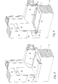
- the in the Fig. 1 and Fig. 2 illustrated first embodiment of the invention shows a kit 1 for the production of a window sill following the window frame 10 of a window, not shown, which is in a window opening, such as a wall, with a thermal barrier coating 11 and two plaster layers 12, 13 is arranged.
- a window opening such as a wall
- the kit 1 consists essentially of a trough-like guide element 2, in which the actual window sill element 3 is inserted after completion of all plastering and painting work.
- the sill element 3 is plate-shaped and may for example consist of artificial or natural stone.
- the guide element 2 has on the base profile fastening means 4 (for example, in the holes insertable screws or a bond) for fixing on the window stock 10. However, it is also possible to fasten the guide element 2 additionally or exclusively to the wall, for example by gluing it to the thermal barrier coating 11.
- Fig. 2 shows the kit 1 after completing the plastering and before inserting the window sill element 3.
- the guide element 2 has in the region of each window reveal 14 a guide rail 5 for the window sill element 3 (see detail in FIG Fig. 5 ), which is inserted into an undercut 15 of the body side heat-insulating layer 11.
- the trough-like guide element 2 consists essentially of a base profile 6 with a insulating layer 11 covering the sealing leg 19, and from the lateral guide rails 5, which can be plugged or clipped onto the base profile 6 (see Fig. 6 and Fig. 7 ).
- the base profile 6 has the attachment means 4 for attachment to the window stock 10 and may also have a retaining leg 20 which engages in a groove formed in the window sill profile.
- the truncated base profile 6 preferably extends over the entire length of the window sill, but may also consist only of lateral sections which are connected by foil material.
- the lateral guide rail 5 in addition to a U-shaped receptacle 7 for the sill element 3, a groove-shaped receptacle 8, which receives the end portion 9 of the base profile 6.
- the lateral guide rails 5 can be easily attached to the cut to the desired length base profile 6, wherein in the corner disturbing web portions of the base profile 6 are disengaged prior to assembly (see Fig. 6 and Fig. 7 ).
- the guide rail 5 can - as in Fig. 2 indicated by dashed lines - have an integrally molded or along the guide rail 5 movably fixed plaster legs 21, if necessary, with a reinforcing grid 22, to avoid cracking in this area of the plaster layers 12, 13. It is characterized relative movements between plaster and guide rail possible, such as in the AT 505.957 . Fig. 4 , described.
- Both the guide rails 5 and the base profile 6 can be present as rod goods and cut to the desired length on site.
- the kit 1 according to the invention may further comprise insulation elements 16 which can be inserted into the thermal barrier coating 11 of the window reveal 14 and which each have a preformed undercut 15 for receiving one of the lateral guide rails 5 of the guide element 2.
- insulation elements 16 which can be inserted into the thermal barrier coating 11 of the window reveal 14 and which each have a preformed undercut 15 for receiving one of the lateral guide rails 5 of the guide element 2. The production of the recess or undercut 15 is thereby simplified.
- the second embodiment according to FIG. 3 and FIG. 4 differs mainly by a window sill element 3 from a single or multiple folded, preferably coated metal profile, for example, aluminum, for fixing the side guide rails 5 and the base member. 6 additional groove-shaped receptacles 17 and 18 have (see Fig. 8 to Fig. 10 ).
- the window sill element 3 After inserting the window sill element 3 into the guide element 2, the window sill element 3 can be fastened or sealed to the guide element 2 at least in individual regions with a permanently elastic adhesive, for example silicone.
- a permanently elastic adhesive for example silicone.
Landscapes
- Engineering & Computer Science (AREA)
- Civil Engineering (AREA)
- Structural Engineering (AREA)
- Door And Window Frames Mounted To Openings (AREA)
Applications Claiming Priority (1)
| Application Number | Priority Date | Filing Date | Title |
|---|---|---|---|
| AT3902011A AT511098B1 (de) | 2011-03-18 | 2011-03-18 | Bausatz zur herstellung einer fensterbank |
Publications (2)
| Publication Number | Publication Date |
|---|---|
| EP2500502A2 true EP2500502A2 (fr) | 2012-09-19 |
| EP2500502A3 EP2500502A3 (fr) | 2014-07-02 |
Family
ID=45894183
Family Applications (1)
| Application Number | Title | Priority Date | Filing Date |
|---|---|---|---|
| EP12159449.3A Withdrawn EP2500502A3 (fr) | 2011-03-18 | 2012-03-14 | Kit de fabrication d'un rebord de fenêtre |
Country Status (2)
| Country | Link |
|---|---|
| EP (1) | EP2500502A3 (fr) |
| AT (1) | AT511098B1 (fr) |
Cited By (7)
| Publication number | Priority date | Publication date | Assignee | Title |
|---|---|---|---|---|
| WO2015058862A1 (fr) * | 2013-10-25 | 2015-04-30 | Armin Wigand | Ensemble appui de fenêtre |
| EP3153652A1 (fr) * | 2015-10-09 | 2017-04-12 | WEKU KG Fenster + Türen | Dispositif de rebord de fenêtre pour recouvrir une section de mur sous une fenêtre |
| CN106593192A (zh) * | 2017-01-11 | 2017-04-26 | 广东星艺装饰集团股份有限公司 | 窗台大理石防水结构 |
| DE202017006964U1 (de) | 2017-09-27 | 2019-01-08 | Andreas Brummer | Fensterbankbefestigungsvorrichtung zur Befestigung einer Fensterbank, Fensterbankauflagevorrichtung zur Auflage einer Fensterbank sowie Fensterbankmontagesystem zur Befestigung einer Fensterbank in einer Fensterlaibung |
| CN109386210A (zh) * | 2018-08-08 | 2019-02-26 | 浙江亚厦幕墙有限公司 | 一种石材窗台板的连接结构 |
| EP3992407A1 (fr) * | 2020-10-07 | 2022-05-04 | Günther Muller | Élément isolant |
| EP4715155A1 (fr) * | 2024-09-20 | 2026-03-25 | Daw Se | Section de rebord de fenêtre inférieure avec élément de réception avec bord de tirage pour recevoir un rebord de fenêtre |
Families Citing this family (1)
| Publication number | Priority date | Publication date | Assignee | Title |
|---|---|---|---|---|
| DE202017107600U1 (de) * | 2017-12-14 | 2019-04-29 | ST Extruded Products Germany GmbH | System zur Montage einer Fensterbank an einer Außenfassade |
Citations (2)
| Publication number | Priority date | Publication date | Assignee | Title |
|---|---|---|---|---|
| DE202008004201U1 (de) | 2008-03-26 | 2008-05-29 | Sto Ag | Fensterbank |
| AT505957A1 (de) | 2007-06-19 | 2009-05-15 | Ortner Jerome | Spreizvorrichtung zum einbau von zargen |
Family Cites Families (5)
| Publication number | Priority date | Publication date | Assignee | Title |
|---|---|---|---|---|
| DE1926880U (de) * | 1965-01-29 | 1965-11-11 | Peter Mueller | Dreiseitenrahmen mit dazugehoeriger einschiebesims. |
| DE6604587U (de) * | 1965-03-09 | 1970-01-22 | Uhl Kg Fa Geb | Aufschiebbares abschlussstueck fuer metallfensterbaenke |
| DE1931325U (de) * | 1965-12-03 | 1966-01-20 | Ver Deutsche Metallwerke Ag | Abschlussprofilstueck fuer fensterbaenke u. dgl. |
| DE9305774U1 (de) * | 1993-04-16 | 1993-07-08 | Erhardt, Gustav, 6967 Buchen | Fensterbank |
| DE29920777U1 (de) * | 1999-11-26 | 2000-01-27 | Menke Kunststoffe GmbH & Co. KG, 59581 Warstein | Fensteranordnung |
-
2011
- 2011-03-18 AT AT3902011A patent/AT511098B1/de active
-
2012
- 2012-03-14 EP EP12159449.3A patent/EP2500502A3/fr not_active Withdrawn
Patent Citations (2)
| Publication number | Priority date | Publication date | Assignee | Title |
|---|---|---|---|---|
| AT505957A1 (de) | 2007-06-19 | 2009-05-15 | Ortner Jerome | Spreizvorrichtung zum einbau von zargen |
| DE202008004201U1 (de) | 2008-03-26 | 2008-05-29 | Sto Ag | Fensterbank |
Cited By (9)
| Publication number | Priority date | Publication date | Assignee | Title |
|---|---|---|---|---|
| WO2015058862A1 (fr) * | 2013-10-25 | 2015-04-30 | Armin Wigand | Ensemble appui de fenêtre |
| EP3153652A1 (fr) * | 2015-10-09 | 2017-04-12 | WEKU KG Fenster + Türen | Dispositif de rebord de fenêtre pour recouvrir une section de mur sous une fenêtre |
| CN106593192A (zh) * | 2017-01-11 | 2017-04-26 | 广东星艺装饰集团股份有限公司 | 窗台大理石防水结构 |
| DE202017006964U1 (de) | 2017-09-27 | 2019-01-08 | Andreas Brummer | Fensterbankbefestigungsvorrichtung zur Befestigung einer Fensterbank, Fensterbankauflagevorrichtung zur Auflage einer Fensterbank sowie Fensterbankmontagesystem zur Befestigung einer Fensterbank in einer Fensterlaibung |
| DE102017122516A1 (de) | 2017-09-27 | 2019-03-28 | Andreas Brummer | Fensterbankbefestigungsvorrichtung zur Befestigung einer Fensterbank, Fensterbankauflagevorrichtung zur Auflage einer Fensterbank sowie Fensterbankmontagesystem zur Befestigung einer Fensterbank in einer Fensterlaibung |
| DE102017122516B4 (de) | 2017-09-27 | 2021-11-11 | Andreas Brummer | Fensterbankbefestigungsvorrichtung zur Befestigung einer Fensterbank, Fensterbankauflagevorrichtung zur Auflage einer Fensterbank sowie Fensterbankmontagesystem zur Befestigung einer Fensterbank in einer Fensterlaibung |
| CN109386210A (zh) * | 2018-08-08 | 2019-02-26 | 浙江亚厦幕墙有限公司 | 一种石材窗台板的连接结构 |
| EP3992407A1 (fr) * | 2020-10-07 | 2022-05-04 | Günther Muller | Élément isolant |
| EP4715155A1 (fr) * | 2024-09-20 | 2026-03-25 | Daw Se | Section de rebord de fenêtre inférieure avec élément de réception avec bord de tirage pour recevoir un rebord de fenêtre |
Also Published As
| Publication number | Publication date |
|---|---|
| AT511098B1 (de) | 2012-09-15 |
| AT511098A4 (de) | 2012-09-15 |
| EP2500502A3 (fr) | 2014-07-02 |
Similar Documents
| Publication | Publication Date | Title |
|---|---|---|
| AT511098B1 (de) | Bausatz zur herstellung einer fensterbank | |
| EP2093368B1 (fr) | Profilé de raccordement d'intrados pour composants limitrophes d'un enduit | |
| EP2116683A2 (fr) | Profil de raccordement pour des composants limités par un enduit sur des couches de matériaux isolants | |
| EP2511465A2 (fr) | Profilé de bordure et procédé de montage d'un rebord de fenêtre | |
| EP2853653A2 (fr) | Bande de crépissage, bande et rail de terminaison | |
| EP1674649B1 (fr) | Profilé de raccord à deux pièces pour éléments de construction voisins d'un crépi | |
| DE102014116372B4 (de) | Profilleiste zur Anbringung an einem unteren Rahmenschenkel eines Fenster- oder Türrahmens im Bereich des Übergangs zum Mauerwerk | |
| EP2762668B1 (fr) | Profil de raccordement | |
| DE102019008345A1 (de) | Führungsschiene einer Gebäudeöffnungsverschattungsvorrichtung, Anputzprofil für die Führungsschiene, sowie Verfahren zur Montage der Führungsschiene | |
| DE202009011103U1 (de) | Sockelprofilleiste für Dämmplatten | |
| DE102010009376A1 (de) | Putzabschlussprofil und Verfahren zur Herstellung eines Anschlusses zwischen zwei Wänden | |
| DE202012007697U1 (de) | Anputzleiste, Abschlussschiene und Putz-Eckleiste | |
| AT506968B1 (de) | Anschlussprofil für an dämmstofflagen mit putz angrenzende bauteile | |
| DE102015108708A1 (de) | Kombiniertes Dicht- und Dämmsystem | |
| EP3168403B1 (fr) | Système d'isolation et d'étanchéification combiné | |
| EP3653805B1 (fr) | Profil de raccordement | |
| AT506795A4 (de) | Anschlussprofil für an putz angrenzende bauteile | |
| DE102011002676A1 (de) | Flügel einer Tür, eines Fensters oder dergleiche, sowie Verfahren zur Herstellung eines Flügels einer Tür, eines Fensters oder dergleichen | |
| DE3717317A1 (de) | Fensterlaibungsverkleidung | |
| EP1548197A1 (fr) | Dispositif et procédé pour l'étanchéification de joints de constructions, en particulier pour des joints d'expansion de façade | |
| DE102016002529A1 (de) | Einbaufähiges Fensterbankmodul | |
| DE102017122516B4 (de) | Fensterbankbefestigungsvorrichtung zur Befestigung einer Fensterbank, Fensterbankauflagevorrichtung zur Auflage einer Fensterbank sowie Fensterbankmontagesystem zur Befestigung einer Fensterbank in einer Fensterlaibung | |
| EP2932007B1 (fr) | Rebord de fenêtre et pièce terminale associée | |
| EP2829680A1 (fr) | Profil destiné au montage d'un rebord de fenêtre et kit de montage à isolation thermique de celui-ci | |
| AT12374U1 (de) | Fugendichtband |
Legal Events
| Date | Code | Title | Description |
|---|---|---|---|
| PUAI | Public reference made under article 153(3) epc to a published international application that has entered the european phase |
Free format text: ORIGINAL CODE: 0009012 |
|
| AK | Designated contracting states |
Kind code of ref document: A2 Designated state(s): AL AT BE BG CH CY CZ DE DK EE ES FI FR GB GR HR HU IE IS IT LI LT LU LV MC MK MT NL NO PL PT RO RS SE SI SK SM TR |
|
| AX | Request for extension of the european patent |
Extension state: BA ME |
|
| 111Z | Information provided on other rights and legal means of execution |
Free format text: AL AT BE BG CH CY CZ DE DK EE ES FI FR GB GR HR HU IE IS IT LT LU LV MC MK MT NL NO PL PT RO RS SE SI SK SM TR Effective date: 20130314 |
|
| RAP1 | Party data changed (applicant data changed or rights of an application transferred) |
Owner name: AF TEC BETEILIGUNGS GMBH |
|
| RIN1 | Information on inventor provided before grant (corrected) |
Inventor name: MICK, STEFAN Inventor name: KASSMANNHUBER, PETER |
|
| PUAL | Search report despatched |
Free format text: ORIGINAL CODE: 0009013 |
|
| AK | Designated contracting states |
Kind code of ref document: A3 Designated state(s): AL AT BE BG CH CY CZ DE DK EE ES FI FR GB GR HR HU IE IS IT LI LT LU LV MC MK MT NL NO PL PT RO RS SE SI SK SM TR |
|
| AX | Request for extension of the european patent |
Extension state: BA ME |
|
| RIC1 | Information provided on ipc code assigned before grant |
Ipc: E06B 1/70 20060101AFI20140527BHEP Ipc: E06B 1/68 20060101ALI20140527BHEP |
|
| STAA | Information on the status of an ep patent application or granted ep patent |
Free format text: STATUS: THE APPLICATION IS DEEMED TO BE WITHDRAWN |
|
| 18D | Application deemed to be withdrawn |
Effective date: 20150106 |