EP2116683A2 - Profil de raccordement pour des composants limités par un enduit sur des couches de matériaux isolants - Google Patents
Profil de raccordement pour des composants limités par un enduit sur des couches de matériaux isolants Download PDFInfo
- Publication number
- EP2116683A2 EP2116683A2 EP09159605A EP09159605A EP2116683A2 EP 2116683 A2 EP2116683 A2 EP 2116683A2 EP 09159605 A EP09159605 A EP 09159605A EP 09159605 A EP09159605 A EP 09159605A EP 2116683 A2 EP2116683 A2 EP 2116683A2
- Authority
- EP
- European Patent Office
- Prior art keywords
- profile
- strip
- component
- connection profile
- connection
- Prior art date
- Legal status (The legal status is an assumption and is not a legal conclusion. Google has not performed a legal analysis and makes no representation as to the accuracy of the status listed.)
- Granted
Links
Images


Classifications
-
- E—FIXED CONSTRUCTIONS
- E06—DOORS, WINDOWS, SHUTTERS, OR ROLLER BLINDS IN GENERAL; LADDERS
- E06B—FIXED OR MOVABLE CLOSURES FOR OPENINGS IN BUILDINGS, VEHICLES, FENCES OR LIKE ENCLOSURES IN GENERAL, e.g. DOORS, WINDOWS, BLINDS, GATES
- E06B1/00—Border constructions of openings in walls, floors, or ceilings; Frames to be rigidly mounted in such openings
- E06B1/62—Tightening or covering joints between the border of openings and the frame or between contiguous frames
-
- E—FIXED CONSTRUCTIONS
- E04—BUILDING
- E04F—FINISHING WORK ON BUILDINGS, e.g. STAIRS, FLOORS
- E04F13/00—Coverings or linings, e.g. for walls or ceilings
- E04F13/02—Coverings or linings, e.g. for walls or ceilings of plastic materials hardening after applying, e.g. plaster
- E04F13/04—Bases for plaster
- E04F13/06—Edge-protecting borders
- E04F13/068—Edge-protecting borders combined with mesh material or the like to allow plaster to bond therewith
-
- E—FIXED CONSTRUCTIONS
- E04—BUILDING
- E04G—SCAFFOLDING; FORMS; SHUTTERING; BUILDING IMPLEMENTS OR AIDS, OR THEIR USE; HANDLING BUILDING MATERIALS ON THE SITE; REPAIRING, BREAKING-UP OR OTHER WORK ON EXISTING BUILDINGS
- E04G21/00—Preparing, conveying, or working-up building materials or building elements in situ; Other devices or measures for constructional work
- E04G21/24—Safety or protective measures preventing damage to building parts or finishing work during construction
- E04G21/30—Safety or protective measures preventing damage to building parts or finishing work during construction against mechanical damage or dirt, e.g. guard covers of stairs
-
- E—FIXED CONSTRUCTIONS
- E04—BUILDING
- E04F—FINISHING WORK ON BUILDINGS, e.g. STAIRS, FLOORS
- E04F13/00—Coverings or linings, e.g. for walls or ceilings
- E04F13/02—Coverings or linings, e.g. for walls or ceilings of plastic materials hardening after applying, e.g. plaster
- E04F13/04—Bases for plaster
- E04F13/06—Edge-protecting borders
- E04F2013/063—Edge-protecting borders for corners
-
- E—FIXED CONSTRUCTIONS
- E06—DOORS, WINDOWS, SHUTTERS, OR ROLLER BLINDS IN GENERAL; LADDERS
- E06B—FIXED OR MOVABLE CLOSURES FOR OPENINGS IN BUILDINGS, VEHICLES, FENCES OR LIKE ENCLOSURES IN GENERAL, e.g. DOORS, WINDOWS, BLINDS, GATES
- E06B1/00—Border constructions of openings in walls, floors, or ceilings; Frames to be rigidly mounted in such openings
- E06B1/62—Tightening or covering joints between the border of openings and the frame or between contiguous frames
- E06B2001/624—Tightening or covering joints between the border of openings and the frame or between contiguous frames with parts to be embedded in the stucco layer or otherwise linked to this layer
Definitions
- the invention relates to a connection profile for insulating material layers with plaster adjacent components, such as window or door frames, with a base profile which is fixed to the component and having a retaining web, wherein the base profile in the installed position of a holding web of the base profile and at least partially from the component limited, preferably U-shaped receiving space forms.
- connection profile When installing the connection profile, the base profile is first glued to the component and then an insulating layer is used, which is aligned at the edge of the retaining bar. Thereafter, the outer profile is inserted with its mounting legs in the U-shaped receiving space, which is formed by the holding web and the adjacent region of the component. Subsequently, the Einsputzschenkel is fixed by means of an adhesive tape arranged on the back of the insulating layer. After installation of the connection profile whose outer leg can compensate for both movements in the plane of the component and tensile movements in a direction away from the fixture.
- the fastening leg and / or the spring element are made elastic by material selection or shaping in order to react elastically to relative movements between the components.
- a sealing strip for adhering to a frame part has become known, in which the Foam strip is arranged in the compressed state closed in a substantially U-shaped channel of the sealing strip.
- the channel is closed in the direction of the installation part by a dimensionally stable cover strip, which is held at the edge in a releasable form-fit engagement connection to the end region of the channel walls.
- the dimensionally stable cover strip can be removed by means of a film passing through the engagement compound after installation of the sealing strip, so that the sealing strip is released and deployed between the base of the sealing strip and connected to the insert by an adhesive strip, dimensionally stable cover strip.
- the disadvantage is the relatively complicated structure and the component side not unproblematic handling.
- a two-part soffit connection profile which has a base profile which can be fastened to the component, and an outer profile which can be fixed movably by the base profile and which has a plastering leg.
- the outer profile consists of a flexible material and is rolled up in front of the intended fixation on the base profile, wherein the outer profile has a mounting leg, which can be inserted after attachment of the base profile on the component between an integrally formed on the base profile, resilient retaining web and the component itself.
- the base profile may also consist of a flexible material and be rolled up before being mounted for storage and transport.
- the object of the invention is to provide a soffit connection profile, with which when using an insulating layer on the one hand a permanent seal between the facade and the adjacent components can be achieved and on the other hand relative movements between plaster and component can be compensated to a sufficient extent. Furthermore, the connection profile should be easy to produce and easy to assemble.
- an elastic sealing strip or an expanding sealing strip can be used, which rests sealingly after its deployment on the component and the retaining web of the base profile.
- the elastic or expanding sealing tape - in contrast to the execution according to EP 0 530 653 A1 - Used on site by hand in a receiving space, which is produced only by gluing the base profile to the base part.
- the elastic or expandable sealing strip is preferably in the form of rolled goods and can be adapted to the respective profile length without significant waste, and can be pressed into the receiving space of the base profile seamlessly.
- the holding web of the base profile on a groove-shaped receptacle which receives a mounting leg of an outer profile the cleaning strip largely covers the elastic or expanding sealing tape on the visible side.
- the profile profile very simply designed outer profile is preferably present as a roll, this can be used seamlessly in the groove-shaped receptacle of the base profile, so that little waste accumulates and butt joints (except in the corners of the window and door frames) can be avoided.
- the outer profile is inserted according to a second advantageous embodiment of the invention only after the completion of all plastering work in the base profile.
- the retaining web of the base profile on a groove-shaped receptacle which receives a mounting leg of the outer profile, wherein a cover strip of the outer profile on the visible side at least largely covers the elastic or expanding sealing tape.
- the outer profile on the cover strip or instead of the cover strip have a voltage applied to the component sealing lip
- an elastic sealing strip which has, for example, a hollow chamber into the receiving space of the base element, which rests elastically on the component and on the retaining web of the base profile after insertion by its restoring force.
- the elastic sealing strip can be introduced as single or multi-component foam in the receiving space.
- the retaining web emanating from a foot part can have a retaining edge projecting in the direction of the component for fixing the elastic or expanding sealing band.
- connection profile When inserting the individual elements of the insulating material layer usually a gap of irregular height to the connection profile is unavoidable, so that leaks and cold spots in the connection area can arise here.
- at least one sealing element which is elastically deformable and closes the gap between the connection profile and the insulating material layer, can now be arranged between the connection profile and the front and / or side surfaces of the insulating material layer facing the connection profile.
- the sealing lips consist of a material which is softer compared to the base profile, for example of TPE, and can be produced by coextrusion.
- the end profile facing the connection profile and / or side surfaces of the insulating material layer can have at least one elastically deformable sealing element, which can be fastened to these end and / or side surfaces or integrated into the end and / or side surfaces.
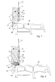
- connection profile 1 In the Fig. 1 to Fig. 4 the installation sequence of the first embodiment of the connection profile 1 according to the invention is shown (two-part profile).
- the base profile 2 of the connection profile 1 with its foot part 30 is glued to a window or door frame 10.
- the base profile 2 has a substantially U-shaped receiving space 6 for an expanding sealing strip, wherein the receiving space 6 is bounded by a holding web 5 and at least partially directly from the component 10.
- the holding web 5 has a groove-shaped receptacle 8, which is for receiving the outer profile 3 (s. FIG. 3 and FIG. 4 ) serves.
- the groove-shaped receptacle 8 of the retaining leg 5 consists of a first leg 15 and a second leg 17, the free end serves as a trigger edge 18 for a filler 13, which is applied to the insulating element 11 of an insulating layer.
- second leg 17 of the receptacle 8 has a Einputzschenkel 19, which forms an angle of approximately 90 ° with the holding web 5.
- Fig. 1 Thus shows the first step of the assembly, in which the base profile 2 glued to the component 10 and an insulating element 11 used, and the filler 13 is applied.
- an expanding sealing tape 7 on site (on site) used which was unwound from a sealing tape roll and cut to the required length.
- the sealing element 7 bears against the component 10 and the retaining web 5 of the base profile 2 in a sealing manner.
- An additional anchoring of the sealing strip 7 is effected by a holding edge 16 or a shoulder which is formed on the first leg 15 of the receptacle 8 (s. Fig. 2 ).
- the expanding sealing strip 7 without interruption in the receiving spaces 6 of two at a corner of the component 10 abutting base profiles 2 continue to lead, whereby the corner areas of window and door sashes (except for one butt joint per fitting) are optimally sealed ,
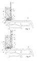
- the outer profile 3 is inserted into the groove-shaped receptacle 8, wherein the receptacle 8 accommodates a mounting leg 9 of the outer profile 3 and the cleaning strip 4 largely covers the expanding sealing strip 7 on the visible side. Seen from the outside, only a small gap remains visible between the cleaning strip 4 and the component 10, wherein the cleaning strip 4 may also rest on the component 10 or at this point a sealing lip may be provided.
- the last step is according to Fig. 4 applied a layer of noble plaster 12 and removed on the cleaning strip 4.
- the outer profile 3 After inserting the expanding sealing strip 7 in the receiving space 6, the outer profile 3 is inserted into the groove-shaped receptacle 8, wherein according to the invention on the cleaning strip 4 of the outer profile 3, a second, detachable protective leg 24 is disposed with an adhesive film 25.
- the outer profile 3 together with the protective leg 24 is present as a rolled product and can be used without significant waste while avoiding butt joints in the groove-shaped receptacle 8 of the base profile 2.
- After the application of the plaster layer 12 and the second protective leg 24 can be separated at its predetermined breaking point for cleaning strip 4, so that according to the installation situation Fig. 4 arrives. Subsequent movements between plaster 13 and component 10 can be absorbed by the relatively large volume expanding sealing strip 7.
- the sealing tape may for example consist of an impregnated, open-cell polyurethane foam.
- connection profile 1 In the Fig. 6 to Fig. 11 the installation sequence of the second embodiment of the connection profile 1 according to the invention is shown (two-part profile).
- the base profile 2 of the connection profile 1 is glued with its foot part 30 on a window or door frame 10.
- the base profile 2 has - first embodiment variant - a substantially U-shaped receiving space 6 for an elastic or expanding sealing tape.
- the holding web 5 has a groove-shaped receptacle 8, which is for receiving the outer profile 3 (s. Fig. 9 ) serves.
- the groove-shaped receptacle 8 of the retaining leg 5 consists of a first leg 15 and a second leg 17, the free end has a trigger edge 18 for a filler 13, which is applied to the insulating element 11 of an insulating layer. Furthermore, the free end of the leg points 17 a cleaning strip 28 on which the noble plaster 12 (s. Fig. 7 ) can be deducted.
- Fig. 6 Thus shows the first step of the assembly, in which the base profile 2 glued to the component 10 and an insulating element 11 used, and the filler 13 is applied.
- a layer of noble plaster 12 is applied and removed from the cleaning strip 28.
- Fig. 8 used as a third step, for example, an expanding sealing strip 7, which was unwound from a sealing tape roll and cut to the required length.
- the sealing element 7 bears elastically and sealingly on the component 10 and on the retaining web 5 of the base profile 2.
- An additional anchoring of the sealing strip 7 is effected by a retaining edge 16 or a shoulder which is formed on the first leg 15 of the groove-shaped receptacle 8 (s. Fig. 8 ).
- an elastic sealing strip 7 ' for example, a hollow chamber seal or a tubular seal, are used, the cross section is compressed upon insertion into the receiving space 6. After insertion, the sealing tape 7 'unfolds and fills the receiving space 6.
- the outer profile 3 is inserted into the groove-shaped receptacle 8, wherein the receptacle 8 receives a mounting leg 9 of the outer profile 3 and a cover strip 26 of the outer profile 3, the sealing tape 7 on the visible side at least largely covers.
- the mounting leg 9 is fixed for example by a locking element 14 in the receptacle 8.
- the outer profile 3 After inserting the expanding or elastic sealing strip 7, 7 'in the receiving space 6, the outer profile 3 is inserted into the groove-shaped receptacle 8.
- the outer profile 3 with the sealing lip 27 is present as a rolled product and can be used without substantial waste while avoiding butt joints in the groove-shaped receptacle 8 of the base profile 2.
- the sealing tape may for example consist of an impregnated, open-cell polyurethane foam or be designed as a tubular hollow chamber seal.
- the holding web 5 of the base profile 2 is made in two parts and allows a relative movement of the two parts in the direction of the profile axis.
- the compound 29 of the two parts of the holding web 5 is designed for example as a sliding connection.
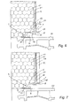
- connection profile 1 In the FIGS. 12 to 15 subvariants of a third embodiment of the connection profile 1 according to the invention are shown (one-piece profile).
- the base profile 2 of the connection profile for example, by means of adhesive tape 37 glued to a window or door frame 10.
- the base profile 2 here also has a substantially U-shaped receiving space 6 for an elastic or expanding sealing strip 7, the receiving space 6 being bounded by a holding web 5 and at least partially directly by the component 10.
- the outgoing from a foot part 30 retaining web 5 has a projecting member 10 holding edge 16 for fixing the on-site in the receiving space 6 retractable, elastic or expanding sealing strip 7, 7 'on.
- a trigger edge 18 is provided for a filler 13, which is applied to the insulation layer 11. Furthermore, the free end of the retaining bar 5 has a cleaning strip 28, on which the noble plaster 12 can be removed.
- the side facing away from the component 10 of the holding web 5 has a Einputzschenkel 19, which forms an angle of about 90 ° with the holding web 5.
- connection profile 1 When inserting the individual elements of the Dämmstofflage 11 undesirable column S1, S2 with irregular gap width between the front and side surfaces 35, 36 of the insulating elements 11 and the associated parts (base part 2 or Einputzschenkel 19) of the connection profile 1 occur.
- the problem is solved in that between the connection profile 1 and the connection profile facing end and / or side surfaces 35, 36 of the insulating material 11 at least one sealing element 31, 32, 33, 34 is arranged, which is elastically deformable and the gap between the connection profile 1 and 11 Dämmstofflage closes. By this measure, cold bridges are effectively avoided in this area.
- sealing elements 31, 32, 33, 34 can in a similar manner also in the two-part embodiments according to Fig. 1 to Fig. 11 be used.
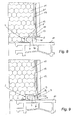
- an elastically deformable sealing lip 31 (see Fig. 14 ), for example made of TPE, be formed, which projects in the direction of Dämmstofflage 11.
- the sealing lip 31 gives way elastically and, even when the profile longitudinal axis variable gap height is sealingly against the end face 35 of the insulating material 11 at.
- an elastic sealing lip 34 may be formed, which is aligned with the side surface 36 of the insulating material layer 11 (see FIGS. 12 to 15 ).
- the end profile 31 facing the connection profile 1 and / or side surfaces 35, 36 of the insulating material layer 11 may have at least one elastically deformable sealing element 33, which is fastened to these surfaces 35, 36 or integrated in these. So shows, for example Fig. 15 a variant in which the sealing strip 33 is adhered to the end face 35 of the insulating material layer 11.
- a layer of noble plaster 12 is applied and peeled off at a cleaning bar 28 of the holding web 5.
- a detachable protective leg 22 is attached to the retaining bar 5, preferably on the cleaning strip 28 for the fine plaster, with an adhesive surface 23 for receiving a cover.
- the last step used is the expanding sealing strip 7, which is unwound from a sealing tape roll and cut to the required length.
- the sealing element 7 bears elastically and sealingly on the component 10 and on the retaining web 5 of the base profile 2. An additional anchoring of the sealing strip 7 takes place through the retaining edge 16 on the holding web. 5
- an elastic sealing band 7 ' (such as in Fig. 11 shown), for example, a hollow chamber seal or a tubular seal, are used, the cross section is compressed upon insertion into the receiving space 6. After insertion, the sealing tape 7 'unfolds and fills the receiving space 6. Furthermore, it is also possible to introduce a one- or multi-component foam in the receiving space 6.
- the sealing strip 7 can for example consist of an impregnated, open-cell polyurethane foam or designed as a tubular hollow chamber seal 7 '.
Landscapes
- Engineering & Computer Science (AREA)
- Architecture (AREA)
- Civil Engineering (AREA)
- Structural Engineering (AREA)
- Mechanical Engineering (AREA)
- Building Environments (AREA)
- Door And Window Frames Mounted To Openings (AREA)
- Securing Of Glass Panes Or The Like (AREA)
Priority Applications (1)
| Application Number | Priority Date | Filing Date | Title |
|---|---|---|---|
| EP12176567.1A EP2514903A3 (fr) | 2008-05-08 | 2009-05-07 | Profil de raccordement pour des composants limités par un enduit sur des couches de matériaux isolants |
Applications Claiming Priority (4)
| Application Number | Priority Date | Filing Date | Title |
|---|---|---|---|
| AT7432008A AT506771B1 (de) | 2008-05-08 | 2008-05-08 | Zweiteiliges anschlussprofil für an putz angrenzende bauteile |
| AT12452008A AT506795B1 (de) | 2008-08-11 | 2008-08-11 | Anschlussprofil für an putz angrenzende bauteile |
| AT13842008A AT506957B1 (de) | 2008-09-04 | 2008-09-04 | Anschlussprofil für an dämmstofflagen mit putz angrenzende bauteile |
| AT13852008A AT506968B1 (de) | 2008-09-04 | 2008-09-04 | Anschlussprofil für an dämmstofflagen mit putz angrenzende bauteile |
Related Child Applications (2)
| Application Number | Title | Priority Date | Filing Date |
|---|---|---|---|
| EP12176567.1A Division EP2514903A3 (fr) | 2008-05-08 | 2009-05-07 | Profil de raccordement pour des composants limités par un enduit sur des couches de matériaux isolants |
| EP12176567.1 Division-Into | 2012-07-16 |
Publications (3)
| Publication Number | Publication Date |
|---|---|
| EP2116683A2 true EP2116683A2 (fr) | 2009-11-11 |
| EP2116683A3 EP2116683A3 (fr) | 2010-11-03 |
| EP2116683B1 EP2116683B1 (fr) | 2012-12-12 |
Family
ID=40911016
Family Applications (2)
| Application Number | Title | Priority Date | Filing Date |
|---|---|---|---|
| EP20090159605 Active EP2116683B1 (fr) | 2008-05-08 | 2009-05-07 | Profil de raccordement pour des composants limités par un enduit sur des couches de matériaux isolants |
| EP12176567.1A Withdrawn EP2514903A3 (fr) | 2008-05-08 | 2009-05-07 | Profil de raccordement pour des composants limités par un enduit sur des couches de matériaux isolants |
Family Applications After (1)
| Application Number | Title | Priority Date | Filing Date |
|---|---|---|---|
| EP12176567.1A Withdrawn EP2514903A3 (fr) | 2008-05-08 | 2009-05-07 | Profil de raccordement pour des composants limités par un enduit sur des couches de matériaux isolants |
Country Status (1)
| Country | Link |
|---|---|
| EP (2) | EP2116683B1 (fr) |
Cited By (11)
| Publication number | Priority date | Publication date | Assignee | Title |
|---|---|---|---|---|
| ITAN20130240A1 (it) * | 2013-12-12 | 2015-06-13 | Luigi Verdini | Profilo di partenza antimuffa per sistemi termoisolanti |
| DE102014101463A1 (de) * | 2014-02-06 | 2015-08-06 | Hanse Haus Gmbh | Rahmenanordnung zur Abdichtung eines Fensters in einer Wandöffnung |
| EP2762668A3 (fr) * | 2013-02-01 | 2015-10-07 | Af Tec Beteiligungs Gmbh | Profil de raccordement |
| EP3037616A2 (fr) | 2014-08-25 | 2016-06-29 | Anna Raml | Profile de jonction pour elements de construction juxtaposes sur un enduit |
| EP3040494A1 (fr) | 2014-08-28 | 2016-07-06 | Anna Raml | Profile de jonction pour elements de construction juxtaposes sur un enduit |
| EP3399130A1 (fr) * | 2017-04-28 | 2018-11-07 | Af Tec Beteiligungs Gmbh | Profilé de raccordement pour composants adjacents au crépi |
| EP3473782A1 (fr) | 2017-10-17 | 2019-04-24 | all-tech Profile GmbH | Profilé de raccordement pour composants adjacents au crépi |
| EP3260289B1 (fr) | 2016-06-09 | 2020-09-02 | Odenwald-Chemie GmbH | Élément composite |
| DE102020120016A1 (de) | 2020-07-29 | 2022-02-03 | Zahner Holding GmbH | Putzprofilleiste |
| ES2900948A1 (es) * | 2020-09-18 | 2022-03-18 | Univ Sevilla | Premarco de autosellado |
| AT527680A4 (de) * | 2024-04-08 | 2025-05-15 | Mick Mag Christian | Anputzdichtleiste |
Families Citing this family (5)
| Publication number | Priority date | Publication date | Assignee | Title |
|---|---|---|---|---|
| AT14775U1 (de) | 2014-10-30 | 2016-05-15 | Mick Christian Mag | Anschlussprofil |
| AT15354U1 (de) | 2016-08-08 | 2017-07-15 | Christian Mick Mag | Anschlussprofilleiste |
| AT522244B1 (de) | 2019-02-19 | 2020-09-15 | AF Tec Beteiligungs GmbH | Anschlussprofil für an putz angrenzende bauteile |
| AT528000B1 (de) | 2024-07-10 | 2025-09-15 | K Uni Kunststoffproduktions U Handels Gmbh | Anschlussprofil für an putz angrenzende bauteile mit dichtschlaufe |
| AT528007B1 (de) | 2024-07-10 | 2025-09-15 | K Uni Kunststoffproduktions U Handels Gmbh | Anschlussprofil für an putz angrenzende bauteile mit selbstvernetzenden und/oder aushärtenden dichtmittel |
Citations (3)
| Publication number | Priority date | Publication date | Assignee | Title |
|---|---|---|---|---|
| EP0530653A1 (fr) | 1991-08-31 | 1993-03-10 | Illbruck Bau-Produkte GmbH & Co. KG | Profilé d'étanchéité |
| EP1674649A1 (fr) | 2004-12-23 | 2006-06-28 | Peter Kassmannhuber | Profilé de raccord à deux pièces pour éléments de construction voisins d'un crépi |
| AT8398U1 (de) | 2005-06-23 | 2006-07-15 | Peter Kassmannhuber | Zweiteiliges laibungsanschlussprofil |
Family Cites Families (8)
| Publication number | Priority date | Publication date | Assignee | Title |
|---|---|---|---|---|
| DE1911710U (de) * | 1965-01-07 | 1965-03-11 | Aluminiumwerke Wutoschingen G | Dichtlippe fuer fenster- und tuerrahmen. |
| DE29607602U1 (de) * | 1996-04-29 | 1996-07-04 | KBE-Vertriebsgesellschaft für Kunststoffprodukte GmbH, 66763 Dillingen | Abdichtleiste zur Abdichtung und Abdeckung von äußeren und inneren Fugen an Bauwerken |
| DE19638930C1 (de) * | 1996-09-23 | 1998-07-02 | Eibel Karl Heinz | Profilsatz zum Überbrücken von Fugen oder Öffnungen |
| AT6229U1 (de) * | 2002-07-18 | 2003-06-25 | Peter Kassmannhuber | Laibungsanschlussprofil |
| AT6500U1 (de) * | 2002-12-19 | 2003-11-25 | Peter Kassmannhuber | Laibungsanschlussprofil |
| AT7272U1 (de) * | 2004-01-21 | 2004-12-27 | Peter Kassmannhuber | Laibungsanschlussprofil für an putz angrenzende bauteile |
| AT7692U1 (de) * | 2004-06-04 | 2005-07-25 | Peter Kassmannhuber | Anschlussprofil für eine putzschicht an die führungsschiene eines rollladens |
| DE202006009790U1 (de) * | 2006-06-21 | 2006-10-12 | Kassmannhuber, Peter | Zweiteiliges Laibungsanschlussprofil |
-
2009
- 2009-05-07 EP EP20090159605 patent/EP2116683B1/fr active Active
- 2009-05-07 EP EP12176567.1A patent/EP2514903A3/fr not_active Withdrawn
Patent Citations (3)
| Publication number | Priority date | Publication date | Assignee | Title |
|---|---|---|---|---|
| EP0530653A1 (fr) | 1991-08-31 | 1993-03-10 | Illbruck Bau-Produkte GmbH & Co. KG | Profilé d'étanchéité |
| EP1674649A1 (fr) | 2004-12-23 | 2006-06-28 | Peter Kassmannhuber | Profilé de raccord à deux pièces pour éléments de construction voisins d'un crépi |
| AT8398U1 (de) | 2005-06-23 | 2006-07-15 | Peter Kassmannhuber | Zweiteiliges laibungsanschlussprofil |
Cited By (17)
| Publication number | Priority date | Publication date | Assignee | Title |
|---|---|---|---|---|
| EP2762668A3 (fr) * | 2013-02-01 | 2015-10-07 | Af Tec Beteiligungs Gmbh | Profil de raccordement |
| ITAN20130240A1 (it) * | 2013-12-12 | 2015-06-13 | Luigi Verdini | Profilo di partenza antimuffa per sistemi termoisolanti |
| DE102014101463A1 (de) * | 2014-02-06 | 2015-08-06 | Hanse Haus Gmbh | Rahmenanordnung zur Abdichtung eines Fensters in einer Wandöffnung |
| DE102014101463B4 (de) * | 2014-02-06 | 2016-11-17 | Hanse Haus Gmbh | Rahmenanordnung zur Abdichtung eines Fensters in einer Wandöffnung |
| EP3037616A2 (fr) | 2014-08-25 | 2016-06-29 | Anna Raml | Profile de jonction pour elements de construction juxtaposes sur un enduit |
| EP3040494A1 (fr) | 2014-08-28 | 2016-07-06 | Anna Raml | Profile de jonction pour elements de construction juxtaposes sur un enduit |
| EP3260289B1 (fr) | 2016-06-09 | 2020-09-02 | Odenwald-Chemie GmbH | Élément composite |
| EP3260289B2 (fr) † | 2016-06-09 | 2023-08-09 | Odenwald-Chemie GmbH | Élément composite |
| EP3399130A1 (fr) * | 2017-04-28 | 2018-11-07 | Af Tec Beteiligungs Gmbh | Profilé de raccordement pour composants adjacents au crépi |
| EP3473782A1 (fr) | 2017-10-17 | 2019-04-24 | all-tech Profile GmbH | Profilé de raccordement pour composants adjacents au crépi |
| DE102020120016A1 (de) | 2020-07-29 | 2022-02-03 | Zahner Holding GmbH | Putzprofilleiste |
| ES2900948A1 (es) * | 2020-09-18 | 2022-03-18 | Univ Sevilla | Premarco de autosellado |
| WO2022058636A1 (fr) * | 2020-09-18 | 2022-03-24 | Universidad De Sevilla | Précadre à auto-scellement |
| AT527680A4 (de) * | 2024-04-08 | 2025-05-15 | Mick Mag Christian | Anputzdichtleiste |
| AT527680B1 (de) * | 2024-04-08 | 2025-05-15 | Mick Mag Christian | Anputzdichtleiste |
| EP4632170A1 (fr) | 2024-04-08 | 2025-10-15 | Christian Mick | Baguette d'étanchéité en plâtre |
| DE202025107689U1 (de) | 2024-04-08 | 2026-01-19 | Christian Mick | Anputzdichtleiste |
Also Published As
| Publication number | Publication date |
|---|---|
| EP2514903A2 (fr) | 2012-10-24 |
| EP2116683A3 (fr) | 2010-11-03 |
| EP2116683B1 (fr) | 2012-12-12 |
| EP2514903A3 (fr) | 2013-11-13 |
Similar Documents
| Publication | Publication Date | Title |
|---|---|---|
| EP2116683B1 (fr) | Profil de raccordement pour des composants limités par un enduit sur des couches de matériaux isolants | |
| EP2093368B1 (fr) | Profilé de raccordement d'intrados pour composants limitrophes d'un enduit | |
| AT507300B1 (de) | Anschlussprofil für an dämmstofflagen mit putz angrenzende bauteile | |
| AT506957B1 (de) | Anschlussprofil für an dämmstofflagen mit putz angrenzende bauteile | |
| EP2116682A2 (fr) | Profil de raccordement pour composants limitrophes sur un enduit | |
| EP3663498B1 (fr) | Baguette de recouvrement | |
| EP3399130B1 (fr) | Profilé de raccordement pour composants adjacents au crépi | |
| AT501439B1 (de) | Laibungsanschlussprofil für an putz und an eine dämmschicht angrenzende bauteile | |
| EP1674649B1 (fr) | Profilé de raccord à deux pièces pour éléments de construction voisins d'un crépi | |
| AT501438B1 (de) | Laibungsanschlussprofil für an putz angrenzende bauteile | |
| AT6500U1 (de) | Laibungsanschlussprofil | |
| AT506795B1 (de) | Anschlussprofil für an putz angrenzende bauteile | |
| AT506968B1 (de) | Anschlussprofil für an dämmstofflagen mit putz angrenzende bauteile | |
| DE102008057798B4 (de) | Zweiteiliges Laibungsanschlussprofil | |
| AT506771B1 (de) | Zweiteiliges anschlussprofil für an putz angrenzende bauteile | |
| AT8398U1 (de) | Zweiteiliges laibungsanschlussprofil | |
| AT516185B1 (de) | Anschlussprofil für an Putz angrenzende Bauteile | |
| DE102007003510A1 (de) | Profilleistenanordnung an einem Blindstock | |
| AT7692U1 (de) | Anschlussprofil für eine putzschicht an die führungsschiene eines rollladens | |
| DE202006009790U1 (de) | Zweiteiliges Laibungsanschlussprofil | |
| EP3653805B1 (fr) | Profil de raccordement | |
| EP1548197A1 (fr) | Dispositif et procédé pour l'étanchéification de joints de constructions, en particulier pour des joints d'expansion de façade | |
| AT6229U1 (de) | Laibungsanschlussprofil | |
| EP4227483A1 (fr) | Moulure | |
| EP1557520A2 (fr) | Profilé de raccord pour plâtre sur éléments de construction voisins |
Legal Events
| Date | Code | Title | Description |
|---|---|---|---|
| PUAI | Public reference made under article 153(3) epc to a published international application that has entered the european phase |
Free format text: ORIGINAL CODE: 0009012 |
|
| AK | Designated contracting states |
Kind code of ref document: A2 Designated state(s): AT BE BG CH CY CZ DE DK EE ES FI FR GB GR HR HU IE IS IT LI LT LU LV MC MK MT NL NO PL PT RO SE SI SK TR |
|
| PUAL | Search report despatched |
Free format text: ORIGINAL CODE: 0009013 |
|
| AK | Designated contracting states |
Kind code of ref document: A3 Designated state(s): AT BE BG CH CY CZ DE DK EE ES FI FR GB GR HR HU IE IS IT LI LT LU LV MC MK MT NL NO PL PT RO SE SI SK TR |
|
| 17P | Request for examination filed |
Effective date: 20110427 |
|
| 17Q | First examination report despatched |
Effective date: 20120313 |
|
| GRAP | Despatch of communication of intention to grant a patent |
Free format text: ORIGINAL CODE: EPIDOSNIGR1 |
|
| GRAS | Grant fee paid |
Free format text: ORIGINAL CODE: EPIDOSNIGR3 |
|
| GRAA | (expected) grant |
Free format text: ORIGINAL CODE: 0009210 |
|
| AK | Designated contracting states |
Kind code of ref document: B1 Designated state(s): AT BE BG CH CY CZ DE DK EE ES FI FR GB GR HR HU IE IS IT LI LT LU LV MC MK MT NL NO PL PT RO SE SI SK TR |
|
| AX | Request for extension of the european patent |
Extension state: AL BA RS |
|
| REG | Reference to a national code |
Ref country code: GB Ref legal event code: FG4D Free format text: NOT ENGLISH |
|
| REG | Reference to a national code |
Ref country code: CH Ref legal event code: EP |
|
| REG | Reference to a national code |
Ref country code: AT Ref legal event code: REF Ref document number: 588421 Country of ref document: AT Kind code of ref document: T Effective date: 20121215 |
|
| REG | Reference to a national code |
Ref country code: CH Ref legal event code: NV Representative=s name: ISLER AND PEDRAZZINI AG, CH |
|
| REG | Reference to a national code |
Ref country code: IE Ref legal event code: FG4D Free format text: LANGUAGE OF EP DOCUMENT: GERMAN |
|
| REG | Reference to a national code |
Ref country code: DE Ref legal event code: R096 Ref document number: 502009005642 Country of ref document: DE Effective date: 20130207 |
|
| REG | Reference to a national code |
Ref country code: CH Ref legal event code: PVP Ref country code: CH Ref legal event code: PUE Owner name: AF TEC BETEILIGUNGS GMBH, AT Free format text: FORMER OWNER: KASSMANNHUBER, PETER, AT |
|
| REG | Reference to a national code |
Ref country code: DE Ref legal event code: R082 Ref document number: 502009005642 Country of ref document: DE Representative=s name: KATSCHER HABERMANN PATENTANWAELTE, DE |
|
| PG25 | Lapsed in a contracting state [announced via postgrant information from national office to epo] |
Ref country code: NO Free format text: LAPSE BECAUSE OF FAILURE TO SUBMIT A TRANSLATION OF THE DESCRIPTION OR TO PAY THE FEE WITHIN THE PRESCRIBED TIME-LIMIT Effective date: 20130312 Ref country code: FI Free format text: LAPSE BECAUSE OF FAILURE TO SUBMIT A TRANSLATION OF THE DESCRIPTION OR TO PAY THE FEE WITHIN THE PRESCRIBED TIME-LIMIT Effective date: 20121212 Ref country code: ES Free format text: LAPSE BECAUSE OF FAILURE TO SUBMIT A TRANSLATION OF THE DESCRIPTION OR TO PAY THE FEE WITHIN THE PRESCRIBED TIME-LIMIT Effective date: 20130323 Ref country code: LT Free format text: LAPSE BECAUSE OF FAILURE TO SUBMIT A TRANSLATION OF THE DESCRIPTION OR TO PAY THE FEE WITHIN THE PRESCRIBED TIME-LIMIT Effective date: 20121212 Ref country code: SE Free format text: LAPSE BECAUSE OF FAILURE TO SUBMIT A TRANSLATION OF THE DESCRIPTION OR TO PAY THE FEE WITHIN THE PRESCRIBED TIME-LIMIT Effective date: 20121212 |
|
| REG | Reference to a national code |
Ref country code: NL Ref legal event code: VDEP Effective date: 20121212 |
|
| RAP2 | Party data changed (patent owner data changed or rights of a patent transferred) |
Owner name: AF TEC BETEILIGUNGS GMBH |
|
| RIN2 | Information on inventor provided after grant (corrected) |
Inventor name: KASSMANNHUBER, PETER Inventor name: MICK, STEFAN |
|
| REG | Reference to a national code |
Ref country code: AT Ref legal event code: PC Ref document number: 588421 Country of ref document: AT Kind code of ref document: T Owner name: AF TEC BETEILIGUNGS GMBH, AT Effective date: 20130328 |
|
| REG | Reference to a national code |
Ref country code: DE Ref legal event code: R082 Ref document number: 502009005642 Country of ref document: DE Representative=s name: KATSCHER HABERMANN PATENTANWAELTE, DE Effective date: 20130327 Ref country code: DE Ref legal event code: R081 Ref document number: 502009005642 Country of ref document: DE Owner name: AF TEC BETEILIGUNGS GMBH, AT Free format text: FORMER OWNER: PETER KASSMANNHUBER,STEFAN MICK, , AT Effective date: 20130327 Ref country code: DE Ref legal event code: R082 Ref document number: 502009005642 Country of ref document: DE Representative=s name: PATENTANWAELTE KATSCHER HABERMANN, DE Effective date: 20130327 Ref country code: DE Ref legal event code: R081 Ref document number: 502009005642 Country of ref document: DE Owner name: AF TEC BETEILIGUNGS GMBH, AT Free format text: FORMER OWNERS: KASSMANNHUBER, PETER, ROTHENTHURN, AT; MICK, STEFAN, MAG., RADENTHEIN, AT Effective date: 20130327 |
|
| REG | Reference to a national code |
Ref country code: LT Ref legal event code: MG4D |
|
| PG25 | Lapsed in a contracting state [announced via postgrant information from national office to epo] |
Ref country code: GR Free format text: LAPSE BECAUSE OF FAILURE TO SUBMIT A TRANSLATION OF THE DESCRIPTION OR TO PAY THE FEE WITHIN THE PRESCRIBED TIME-LIMIT Effective date: 20130313 Ref country code: LV Free format text: LAPSE BECAUSE OF FAILURE TO SUBMIT A TRANSLATION OF THE DESCRIPTION OR TO PAY THE FEE WITHIN THE PRESCRIBED TIME-LIMIT Effective date: 20121212 Ref country code: SI Free format text: LAPSE BECAUSE OF FAILURE TO SUBMIT A TRANSLATION OF THE DESCRIPTION OR TO PAY THE FEE WITHIN THE PRESCRIBED TIME-LIMIT Effective date: 20121212 |
|
| REG | Reference to a national code |
Ref country code: FR Ref legal event code: TP Owner name: AF TEC BETEILIGUNGS GMBH, AT Effective date: 20130502 Ref country code: FR Ref legal event code: GC Effective date: 20130502 |
|
| PG25 | Lapsed in a contracting state [announced via postgrant information from national office to epo] |
Ref country code: BG Free format text: LAPSE BECAUSE OF FAILURE TO SUBMIT A TRANSLATION OF THE DESCRIPTION OR TO PAY THE FEE WITHIN THE PRESCRIBED TIME-LIMIT Effective date: 20130312 Ref country code: EE Free format text: LAPSE BECAUSE OF FAILURE TO SUBMIT A TRANSLATION OF THE DESCRIPTION OR TO PAY THE FEE WITHIN THE PRESCRIBED TIME-LIMIT Effective date: 20121212 Ref country code: IS Free format text: LAPSE BECAUSE OF FAILURE TO SUBMIT A TRANSLATION OF THE DESCRIPTION OR TO PAY THE FEE WITHIN THE PRESCRIBED TIME-LIMIT Effective date: 20130412 Ref country code: SK Free format text: LAPSE BECAUSE OF FAILURE TO SUBMIT A TRANSLATION OF THE DESCRIPTION OR TO PAY THE FEE WITHIN THE PRESCRIBED TIME-LIMIT Effective date: 20121212 |
|
| PG25 | Lapsed in a contracting state [announced via postgrant information from national office to epo] |
Ref country code: RO Free format text: LAPSE BECAUSE OF FAILURE TO SUBMIT A TRANSLATION OF THE DESCRIPTION OR TO PAY THE FEE WITHIN THE PRESCRIBED TIME-LIMIT Effective date: 20121212 Ref country code: NL Free format text: LAPSE BECAUSE OF FAILURE TO SUBMIT A TRANSLATION OF THE DESCRIPTION OR TO PAY THE FEE WITHIN THE PRESCRIBED TIME-LIMIT Effective date: 20121212 Ref country code: PT Free format text: LAPSE BECAUSE OF FAILURE TO SUBMIT A TRANSLATION OF THE DESCRIPTION OR TO PAY THE FEE WITHIN THE PRESCRIBED TIME-LIMIT Effective date: 20130412 Ref country code: PL Free format text: LAPSE BECAUSE OF FAILURE TO SUBMIT A TRANSLATION OF THE DESCRIPTION OR TO PAY THE FEE WITHIN THE PRESCRIBED TIME-LIMIT Effective date: 20121212 |
|
| PLBE | No opposition filed within time limit |
Free format text: ORIGINAL CODE: 0009261 |
|
| STAA | Information on the status of an ep patent application or granted ep patent |
Free format text: STATUS: NO OPPOSITION FILED WITHIN TIME LIMIT |
|
| PG25 | Lapsed in a contracting state [announced via postgrant information from national office to epo] |
Ref country code: DK Free format text: LAPSE BECAUSE OF FAILURE TO SUBMIT A TRANSLATION OF THE DESCRIPTION OR TO PAY THE FEE WITHIN THE PRESCRIBED TIME-LIMIT Effective date: 20121212 |
|
| 26N | No opposition filed |
Effective date: 20130913 |
|
| PG25 | Lapsed in a contracting state [announced via postgrant information from national office to epo] |
Ref country code: HR Free format text: LAPSE BECAUSE OF FAILURE TO SUBMIT A TRANSLATION OF THE DESCRIPTION OR TO PAY THE FEE WITHIN THE PRESCRIBED TIME-LIMIT Effective date: 20121212 Ref country code: CY Free format text: LAPSE BECAUSE OF FAILURE TO SUBMIT A TRANSLATION OF THE DESCRIPTION OR TO PAY THE FEE WITHIN THE PRESCRIBED TIME-LIMIT Effective date: 20121212 |
|
| BERE | Be: lapsed |
Owner name: MICK, STEFAN Effective date: 20130531 Owner name: KASSMANNHUBER, PETER Effective date: 20130531 |
|
| PG25 | Lapsed in a contracting state [announced via postgrant information from national office to epo] |
Ref country code: MC Free format text: LAPSE BECAUSE OF FAILURE TO SUBMIT A TRANSLATION OF THE DESCRIPTION OR TO PAY THE FEE WITHIN THE PRESCRIBED TIME-LIMIT Effective date: 20121212 |
|
| REG | Reference to a national code |
Ref country code: DE Ref legal event code: R097 Ref document number: 502009005642 Country of ref document: DE Effective date: 20130913 |
|
| GBPC | Gb: european patent ceased through non-payment of renewal fee |
Effective date: 20130507 |
|
| REG | Reference to a national code |
Ref country code: IE Ref legal event code: MM4A |
|
| PG25 | Lapsed in a contracting state [announced via postgrant information from national office to epo] |
Ref country code: BE Free format text: LAPSE BECAUSE OF NON-PAYMENT OF DUE FEES Effective date: 20130531 |
|
| PG25 | Lapsed in a contracting state [announced via postgrant information from national office to epo] |
Ref country code: GB Free format text: LAPSE BECAUSE OF NON-PAYMENT OF DUE FEES Effective date: 20130507 Ref country code: IE Free format text: LAPSE BECAUSE OF NON-PAYMENT OF DUE FEES Effective date: 20130507 |
|
| PG25 | Lapsed in a contracting state [announced via postgrant information from national office to epo] |
Ref country code: MT Free format text: LAPSE BECAUSE OF FAILURE TO SUBMIT A TRANSLATION OF THE DESCRIPTION OR TO PAY THE FEE WITHIN THE PRESCRIBED TIME-LIMIT Effective date: 20121212 |
|
| PG25 | Lapsed in a contracting state [announced via postgrant information from national office to epo] |
Ref country code: TR Free format text: LAPSE BECAUSE OF FAILURE TO SUBMIT A TRANSLATION OF THE DESCRIPTION OR TO PAY THE FEE WITHIN THE PRESCRIBED TIME-LIMIT Effective date: 20121212 |
|
| PG25 | Lapsed in a contracting state [announced via postgrant information from national office to epo] |
Ref country code: HU Free format text: LAPSE BECAUSE OF FAILURE TO SUBMIT A TRANSLATION OF THE DESCRIPTION OR TO PAY THE FEE WITHIN THE PRESCRIBED TIME-LIMIT; INVALID AB INITIO Effective date: 20090507 Ref country code: LU Free format text: LAPSE BECAUSE OF NON-PAYMENT OF DUE FEES Effective date: 20130507 Ref country code: MK Free format text: LAPSE BECAUSE OF FAILURE TO SUBMIT A TRANSLATION OF THE DESCRIPTION OR TO PAY THE FEE WITHIN THE PRESCRIBED TIME-LIMIT Effective date: 20121212 |
|
| REG | Reference to a national code |
Ref country code: DE Ref legal event code: R082 Ref document number: 502009005642 Country of ref document: DE Representative=s name: PATENTANWAELTE KATSCHER HABERMANN, DE Ref country code: DE Ref legal event code: R081 Ref document number: 502009005642 Country of ref document: DE Owner name: AF TEC BETEILIGUNGS GMBH, AT Free format text: FORMER OWNER: AF TEC BETEILIGUNGS GMBH, FEISTRITZ AN DER DRAU, AT |
|
| REG | Reference to a national code |
Ref country code: FR Ref legal event code: PLFP Year of fee payment: 8 |
|
| REG | Reference to a national code |
Ref country code: FR Ref legal event code: PLFP Year of fee payment: 9 |
|
| REG | Reference to a national code |
Ref country code: FR Ref legal event code: PLFP Year of fee payment: 10 |
|
| REG | Reference to a national code |
Ref country code: CH Ref legal event code: PCOW Free format text: NEW ADDRESS: ROOSEVELTPLATZ 10, 1090 WIEN (AT) Ref country code: CH Ref legal event code: PVP Ref country code: CH Ref legal event code: PVPA |
|
| P01 | Opt-out of the competence of the unified patent court (upc) registered |
Effective date: 20230512 |
|
| PGFP | Annual fee paid to national office [announced via postgrant information from national office to epo] |
Ref country code: FR Payment date: 20230523 Year of fee payment: 15 Ref country code: CH Payment date: 20230602 Year of fee payment: 15 |
|
| PGFP | Annual fee paid to national office [announced via postgrant information from national office to epo] |
Ref country code: CZ Payment date: 20240509 Year of fee payment: 16 |
|
| PGFP | Annual fee paid to national office [announced via postgrant information from national office to epo] |
Ref country code: IT Payment date: 20240529 Year of fee payment: 16 |
|
| REG | Reference to a national code |
Ref country code: CH Ref legal event code: PL |
|
| PG25 | Lapsed in a contracting state [announced via postgrant information from national office to epo] |
Ref country code: CH Free format text: LAPSE BECAUSE OF NON-PAYMENT OF DUE FEES Effective date: 20240531 |
|
| PG25 | Lapsed in a contracting state [announced via postgrant information from national office to epo] |
Ref country code: FR Free format text: LAPSE BECAUSE OF NON-PAYMENT OF DUE FEES Effective date: 20240531 |
|
| PGFP | Annual fee paid to national office [announced via postgrant information from national office to epo] |
Ref country code: DE Payment date: 20250528 Year of fee payment: 17 |
|
| PGFP | Annual fee paid to national office [announced via postgrant information from national office to epo] |
Ref country code: AT Payment date: 20250528 Year of fee payment: 17 |
|
| PG25 | Lapsed in a contracting state [announced via postgrant information from national office to epo] |
Ref country code: CZ Free format text: LAPSE BECAUSE OF NON-PAYMENT OF DUE FEES Effective date: 20250507 |
|
| PG25 | Lapsed in a contracting state [announced via postgrant information from national office to epo] |
Ref country code: IT Free format text: LAPSE BECAUSE OF NON-PAYMENT OF DUE FEES Effective date: 20250507 |