EP2500635A2 - Fixation permettant le remplacement des OLEDs diodes lumineuses organiques - Google Patents
Fixation permettant le remplacement des OLEDs diodes lumineuses organiques Download PDFInfo
- Publication number
- EP2500635A2 EP2500635A2 EP12160113A EP12160113A EP2500635A2 EP 2500635 A2 EP2500635 A2 EP 2500635A2 EP 12160113 A EP12160113 A EP 12160113A EP 12160113 A EP12160113 A EP 12160113A EP 2500635 A2 EP2500635 A2 EP 2500635A2
- Authority
- EP
- European Patent Office
- Prior art keywords
- oled
- bracket
- holder
- groove
- oleds
- Prior art date
- Legal status (The legal status is an assumption and is not a legal conclusion. Google has not performed a legal analysis and makes no representation as to the accuracy of the status listed.)
- Withdrawn
Links
- 238000012423 maintenance Methods 0.000 title description 5
- 230000000694 effects Effects 0.000 description 3
- 239000013013 elastic material Substances 0.000 description 3
- 238000003780 insertion Methods 0.000 description 3
- 230000037431 insertion Effects 0.000 description 3
- 239000000463 material Substances 0.000 description 3
- 239000002184 metal Substances 0.000 description 3
- 230000010354 integration Effects 0.000 description 2
- 239000000725 suspension Substances 0.000 description 2
- 229910000639 Spring steel Inorganic materials 0.000 description 1
- 238000007792 addition Methods 0.000 description 1
- 239000000853 adhesive Substances 0.000 description 1
- 238000004026 adhesive bonding Methods 0.000 description 1
- 230000001070 adhesive effect Effects 0.000 description 1
- 239000002131 composite material Substances 0.000 description 1
- 239000004020 conductor Substances 0.000 description 1
- 230000007547 defect Effects 0.000 description 1
- 230000002950 deficient Effects 0.000 description 1
- 238000006073 displacement reaction Methods 0.000 description 1
- 229920001971 elastomer Polymers 0.000 description 1
- 239000000806 elastomer Substances 0.000 description 1
- 239000012777 electrically insulating material Substances 0.000 description 1
- 230000005611 electricity Effects 0.000 description 1
- 210000003746 feather Anatomy 0.000 description 1
- 239000011888 foil Substances 0.000 description 1
- 239000011521 glass Substances 0.000 description 1
- 230000005484 gravity Effects 0.000 description 1
- 238000005286 illumination Methods 0.000 description 1
- 238000009434 installation Methods 0.000 description 1
- 238000010409 ironing Methods 0.000 description 1
- 239000004033 plastic Substances 0.000 description 1
- 229910001220 stainless steel Inorganic materials 0.000 description 1
- 239000010935 stainless steel Substances 0.000 description 1
- 239000000758 substrate Substances 0.000 description 1
- 229920001169 thermoplastic Polymers 0.000 description 1
- 229920001187 thermosetting polymer Polymers 0.000 description 1
- 239000004416 thermosoftening plastic Substances 0.000 description 1
- 239000012780 transparent material Substances 0.000 description 1
Images

Classifications
-
- F—MECHANICAL ENGINEERING; LIGHTING; HEATING; WEAPONS; BLASTING
- F21—LIGHTING
- F21V—FUNCTIONAL FEATURES OR DETAILS OF LIGHTING DEVICES OR SYSTEMS THEREOF; STRUCTURAL COMBINATIONS OF LIGHTING DEVICES WITH OTHER ARTICLES, NOT OTHERWISE PROVIDED FOR
- F21V19/00—Fastening of light sources or lamp holders
- F21V19/001—Fastening of light sources or lamp holders the light sources being semiconductors devices, e.g. LEDs
- F21V19/0015—Fastening arrangements intended to retain light sources
- F21V19/0025—Fastening arrangements intended to retain light sources the fastening means engaging the conductors of the light source, i.e. providing simultaneous fastening of the light sources and their electric connections
-
- F—MECHANICAL ENGINEERING; LIGHTING; HEATING; WEAPONS; BLASTING
- F21—LIGHTING
- F21V—FUNCTIONAL FEATURES OR DETAILS OF LIGHTING DEVICES OR SYSTEMS THEREOF; STRUCTURAL COMBINATIONS OF LIGHTING DEVICES WITH OTHER ARTICLES, NOT OTHERWISE PROVIDED FOR
- F21V19/00—Fastening of light sources or lamp holders
- F21V19/001—Fastening of light sources or lamp holders the light sources being semiconductors devices, e.g. LEDs
- F21V19/003—Fastening of light source holders, e.g. of circuit boards or substrates holding light sources
- F21V19/004—Fastening of light source holders, e.g. of circuit boards or substrates holding light sources by deformation of parts or snap action mountings, e.g. using clips
-
- F—MECHANICAL ENGINEERING; LIGHTING; HEATING; WEAPONS; BLASTING
- F21—LIGHTING
- F21V—FUNCTIONAL FEATURES OR DETAILS OF LIGHTING DEVICES OR SYSTEMS THEREOF; STRUCTURAL COMBINATIONS OF LIGHTING DEVICES WITH OTHER ARTICLES, NOT OTHERWISE PROVIDED FOR
- F21V19/00—Fastening of light sources or lamp holders
- F21V19/04—Fastening of light sources or lamp holders with provision for changing light source, e.g. turret
-
- F—MECHANICAL ENGINEERING; LIGHTING; HEATING; WEAPONS; BLASTING
- F21—LIGHTING
- F21S—NON-PORTABLE LIGHTING DEVICES; SYSTEMS THEREOF; VEHICLE LIGHTING DEVICES SPECIALLY ADAPTED FOR VEHICLE EXTERIORS
- F21S8/00—Lighting devices intended for fixed installation
- F21S8/04—Lighting devices intended for fixed installation intended only for mounting on a ceiling or the like overhead structures
- F21S8/06—Lighting devices intended for fixed installation intended only for mounting on a ceiling or the like overhead structures by suspension
-
- F—MECHANICAL ENGINEERING; LIGHTING; HEATING; WEAPONS; BLASTING
- F21—LIGHTING
- F21S—NON-PORTABLE LIGHTING DEVICES; SYSTEMS THEREOF; VEHICLE LIGHTING DEVICES SPECIALLY ADAPTED FOR VEHICLE EXTERIORS
- F21S8/00—Lighting devices intended for fixed installation
- F21S8/04—Lighting devices intended for fixed installation intended only for mounting on a ceiling or the like overhead structures
- F21S8/06—Lighting devices intended for fixed installation intended only for mounting on a ceiling or the like overhead structures by suspension
- F21S8/065—Lighting devices intended for fixed installation intended only for mounting on a ceiling or the like overhead structures by suspension multi-branched, e.g. a chandelier
-
- F—MECHANICAL ENGINEERING; LIGHTING; HEATING; WEAPONS; BLASTING
- F21—LIGHTING
- F21V—FUNCTIONAL FEATURES OR DETAILS OF LIGHTING DEVICES OR SYSTEMS THEREOF; STRUCTURAL COMBINATIONS OF LIGHTING DEVICES WITH OTHER ARTICLES, NOT OTHERWISE PROVIDED FOR
- F21V21/00—Supporting, suspending, or attaching arrangements for lighting devices; Hand grips
- F21V21/14—Adjustable mountings
- F21V21/26—Pivoted arms
- F21V21/28—Pivoted arms adjustable in more than one plane
-
- F—MECHANICAL ENGINEERING; LIGHTING; HEATING; WEAPONS; BLASTING
- F21—LIGHTING
- F21V—FUNCTIONAL FEATURES OR DETAILS OF LIGHTING DEVICES OR SYSTEMS THEREOF; STRUCTURAL COMBINATIONS OF LIGHTING DEVICES WITH OTHER ARTICLES, NOT OTHERWISE PROVIDED FOR
- F21V21/00—Supporting, suspending, or attaching arrangements for lighting devices; Hand grips
- F21V21/14—Adjustable mountings
- F21V21/30—Pivoted housings or frames
-
- F—MECHANICAL ENGINEERING; LIGHTING; HEATING; WEAPONS; BLASTING
- F21—LIGHTING
- F21Y—INDEXING SCHEME ASSOCIATED WITH SUBCLASSES F21K, F21L, F21S and F21V, RELATING TO THE FORM OR THE KIND OF THE LIGHT SOURCES OR OF THE COLOUR OF THE LIGHT EMITTED
- F21Y2105/00—Planar light sources
-
- F—MECHANICAL ENGINEERING; LIGHTING; HEATING; WEAPONS; BLASTING
- F21—LIGHTING
- F21Y—INDEXING SCHEME ASSOCIATED WITH SUBCLASSES F21K, F21L, F21S and F21V, RELATING TO THE FORM OR THE KIND OF THE LIGHT SOURCES OR OF THE COLOUR OF THE LIGHT EMITTED
- F21Y2115/00—Light-generating elements of semiconductor light sources
- F21Y2115/10—Light-emitting diodes [LED]
- F21Y2115/15—Organic light-emitting diodes [OLED]
-
- H—ELECTRICITY
- H01—ELECTRIC ELEMENTS
- H01R—ELECTRICALLY-CONDUCTIVE CONNECTIONS; STRUCTURAL ASSOCIATIONS OF A PLURALITY OF MUTUALLY-INSULATED ELECTRICAL CONNECTING ELEMENTS; COUPLING DEVICES; CURRENT COLLECTORS
- H01R35/00—Flexible or turnable line connectors, i.e. the rotation angle being limited
- H01R35/04—Turnable line connectors with limited rotation angle with frictional contact members
-
- Y—GENERAL TAGGING OF NEW TECHNOLOGICAL DEVELOPMENTS; GENERAL TAGGING OF CROSS-SECTIONAL TECHNOLOGIES SPANNING OVER SEVERAL SECTIONS OF THE IPC; TECHNICAL SUBJECTS COVERED BY FORMER USPC CROSS-REFERENCE ART COLLECTIONS [XRACs] AND DIGESTS
- Y02—TECHNOLOGIES OR APPLICATIONS FOR MITIGATION OR ADAPTATION AGAINST CLIMATE CHANGE
- Y02B—CLIMATE CHANGE MITIGATION TECHNOLOGIES RELATED TO BUILDINGS, e.g. HOUSING, HOUSE APPLIANCES OR RELATED END-USER APPLICATIONS
- Y02B20/00—Energy efficient lighting technologies, e.g. halogen lamps or gas discharge lamps
- Y02B20/30—Semiconductor lamps, e.g. solid state lamps [SSL] light emitting diodes [LED] or organic LED [OLED]
Definitions
- the invention relates to a holder for organic light-emitting diodes (OLED), which simplifies the maintenance of luminaires with OLED.
- OLED organic light-emitting diodes
- Organic light-emitting diodes have been known for some time. Unlike the conventional LED, they can basically be made with any size surface. A distinction is made between transparent and non-transparent OLEDs, depending on whether the support and both electrodes are transparent or only one transparent electrode is present. While transparent OLED emit light in both halves defined by them, intransparent OLED shine only in a half-space, wherein the non-transparent layer can be mirrored to improve the light output.
- Orbeos is a non-transparent mirrored OLED OLED, which is octagonal, has a circular luminous surface and is incorporated into circular fixtures of the luminaire.
- the invention therefore has the task of proposing a holder for OLED bulbs, the maintenance, in particular the installation and removal of the light source, is easily possible. At the same time, functionality and design freedom should be maintained.
- the holder according to the invention can accommodate an OLED so that it is held only at the edge and both surfaces remain free. Therefore, it is equally suitable for transparent as well as non-transparent OLEDs.
- the bracket comprises at least half the circumference of the OLED. If the OLED is inserted in the first position of the holding element in the groove of the bracket, it can not be removed without displacement of the holding element in the second position of the groove. This shift can take place either directly on the retaining element or indirectly through the OLED during insertion or withdrawal.
- OLEDs are available in varying degrees of development.
- the simple OLED, directly from the machine with reflective off-state (switched off state) and also in connection with a coupling-out foil and diffuse off-state is called a simple "panel". This can be supplemented by connected lines;
- the panel is connected to the electrical connections, to frame or other housings or brackets often called “module” in the market depending on the integration level.
- the highest level of integration may include electronics for constant current control. Since the OLED properties open up a broad spectrum of design of the luminaire, in particular a combination of OLED and mounting realized by the invention, simple interchangeability and in particular easy maintenance of the sensitive OLEDs are enormously important.
- the user can bring a simple panel, without electrical connections or other additions directly in function and this just as easily replace in the event of a defect or a change in the property (eg: off-state).
- a "plug &play" solution is virtually implemented and the user is not forced in the event of damage, the entire module and the associated additional components to exchange.
- the holder comes without the connection of electrical contacts or lines, because they are integrated via friction contacts, so that no replacement workers are required for replacement or maintenance.
- the diameter is a straight line passing through the center of gravity of the figure represented by the OLED.
- each diameter has the same length, one can see in squares one largest (diagonal) and one smallest (bisecting) diameter, in ellipses corresponding to the major and minor axes, etc.
- the bracket As a holding element, for example, radially in the bracket screwed from the outside grub screws come into consideration. Even levers that can be held in one or both positions, for example by friction or by spring force come into consideration. Preference is given to elastically deformable retaining elements.
- the bracket itself act as a holding element, if it consists of an elastic material and from the first position in which he holds the OLED, elastic in the second Position can be widened.
- the material for such a bracket may be, for example, a thermoplastic or thermosetting elastomer, a suitable metal such as spring steel or stainless steel, or a composite elastic material.
- the bracket can also be provided with a resilient hinge. The widening of the strap for insertion or removal of the OLED can then be done simply by light pressure on this in the direction of the plane of the bracket.
- the holder according to the invention is particularly suitable for OLED with a certain stiffness, z.
- supports frames or substrates made of glass, metal, rigid plastic.
- resilient elements such as leaf springs, optionally provided with cams, are inserted into the groove and fixed there.
- the insertion or removal of the OLED can take place in the same way as described above for the elastic strap.
- the bracket preferably in the groove, have contact elements which can interact with contacts on the circumference of the OLED.
- these are the described resilient elements.
- These resilient elements may be made of conductive material such as metal and connected to a power source.
- the bracket must be made of an electrically insulating material or insulated against the resilient elements.
- the holder according to the invention may preferably be provided with means that attach to a surface, for example a wall, a ceiling or the surface of a lamp body allow.
- These may be, for example, elements of a screw connection such as threaded pins or sleeves, tabs for gluing or screwing or the like.
- complex luminaires can be constructed with several OLEDs or the OLEDs can also be fastened to a wall or ceiling for illumination purposes.
- these means further comprise articulated connections, such as torsion, thrust and / or ball joints, so that the position of a holder fastened to a wall with OLED can be changed as desired by the user.
- Such joints can also be combined several times, for example in the manner of a gimbal, be provided.
- the means for powering the OLED with electricity such as ballasts with transformers, rectifiers and current limiters can be accommodated in the usual way in the luminaire body or in the wall or ceiling surface. It is also possible to mount them in the holder itself.
- the holder according to the invention can have further light sources, for example LEDs. These can be attached to the bracket. It is also possible to make the bracket hollow and made of transparent material and to attach the other bulbs inside the cavity.
- the holder according to the invention can be designed for OLEDs of different shapes, for example for circular or elliptical OLEDs or those in the form of regular hexagons or octagons.
- the regular hexagon or octagon the smallest diameter should be the distance between parallel sides.
- the bracket is then so large that it encompasses more than half of the corners.
- the bracket receives the shape of the OLED to be recorded, that is, for example, approximately a semicircle or a half ellipse.
- the OLED can lie along the full length of the groove with the edge in it. But it is also possible, for example, to insert an octagonal OLED in a semicircular bracket or a circular OLED in a bracket with the shape of an approximately half hexagon, the OLED is then held only with parts of the edge.
- the holder according to the invention does not have full-surface support or support elements, transparent to intransparent OLEDs can be easily exchanged, if desired.
- FIG. 4 a pendant luminaire with 6 OLED in holders according to FIG. 3 ,
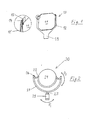
- FIG. 1 shows a holder 10 according to the invention according to a first embodiment with an inserted OLED 11.
- the holder comprises a bracket 12 which is adapted to the octagonal circumference of the OLED and surrounds six of the eight corners of the OLED.
- an outwardly facing projection 19 is attached, which serves to the holder with here Attach fasteners, not shown, such as screws or adhesive to a surface.
- Attach fasteners not shown, such as screws or adhesive to a surface.
- the strap end 12 ' can be seen the groove 13 in which the edge of the OLED 11 rests.
- the spring 14 is fixed in the end 12 'of the bracket and holds the corner of the OLED 11 firmly. As can be seen, when pulling out the OLED 11, the spring 14 in the groove 13 can escape so far outward that the OLED 11 can pass.
- the circular OLED 21 is held in the bracket 22, which here consists of an elastic material and a circular arc of about 190 ° follows.
- the distance between the ends of the bracket 22 in the first position shown is slightly smaller than the diameter of the OLED 21. Pulling the OLED 21 out of the bracket, then the bracket 22 widens in the second position and the edge of the OLED 21 can slide over the ends of the groove in the bracket 22.
- the bracket 22 is in turn connected via pivot joints 26 with a second bracket 27, which in turn is connected via a further pivot 25 with a base 29. This base 29 can now be used to attach to a surface.
- the holder By the hinge 25, the holder can thus be rotated in the direction described by the arrow P1, while the hinges 26 allow rotation in the direction indicated by the arrow P2 direction.
- the power supply to the bracket 22 and thus to the OLED 21 via sliding contacts in the hinges 25 and 26 takes place.
- FIG. 3 shows a further embodiment of the holder according to the invention with a bracket 32, in the groove 33, an OLED 31 is held.
- the bracket 32 is made of an inelastic material and has a spring 34 at at least one end 32 '.
- the mode of action of this spring is similar to that at FIG. 1 discussed spring.
- the bracket 32 is attached via the extension 39 to a base 38 which contains the operating devices for the OLED and are mounted on a wall can.
- FIG. 4 a complex suspension lamp 40 is shown.
- This comprises a lamp base body 41, which can be attached via a suspension 42 to the ceiling.
- holders 30 On the side surfaces of the lamp base body 41 are holders 30 according to FIG. 3 appropriate.
- Such a luminaire can be equipped, for example, with non-transparent OLEDs which only radiate downwards. It is also possible to make the brackets 30 so that the extension 39 is rotatable in the base 38.
Landscapes
- Engineering & Computer Science (AREA)
- General Engineering & Computer Science (AREA)
- Fastening Of Light Sources Or Lamp Holders (AREA)
- Non-Portable Lighting Devices Or Systems Thereof (AREA)
- Electroluminescent Light Sources (AREA)
Applications Claiming Priority (1)
| Application Number | Priority Date | Filing Date | Title |
|---|---|---|---|
| DE102011005808A DE102011005808A1 (de) | 2011-03-18 | 2011-03-18 | Wartungsfreundliche Halterung für organische Leuchtdioden |
Publications (2)
| Publication Number | Publication Date |
|---|---|
| EP2500635A2 true EP2500635A2 (fr) | 2012-09-19 |
| EP2500635A3 EP2500635A3 (fr) | 2014-12-31 |
Family
ID=45887995
Family Applications (1)
| Application Number | Title | Priority Date | Filing Date |
|---|---|---|---|
| EP12160113.2A Withdrawn EP2500635A3 (fr) | 2011-03-18 | 2012-03-19 | Fixation permettant le remplacement des OLEDs diodes lumineuses organiques |
Country Status (2)
| Country | Link |
|---|---|
| EP (1) | EP2500635A3 (fr) |
| DE (1) | DE102011005808A1 (fr) |
Cited By (3)
| Publication number | Priority date | Publication date | Assignee | Title |
|---|---|---|---|---|
| WO2014155247A1 (fr) * | 2013-03-27 | 2014-10-02 | Koninklijke Philips N.V. | Source de lumière à diode électroluminescente organique (delo) en installation rétroactive |
| CN105102877A (zh) * | 2013-03-27 | 2015-11-25 | 皇家飞利浦有限公司 | 改装有机发光二极管(oled)光源 |
| EP2921349B1 (fr) * | 2014-03-17 | 2021-05-12 | Valeo Vision | Module lumineux comportant plusieurs sources lumineuses surfaciques |
Families Citing this family (3)
| Publication number | Priority date | Publication date | Assignee | Title |
|---|---|---|---|---|
| DE102012210484B4 (de) * | 2012-06-21 | 2017-02-02 | Osram Oled Gmbh | Verfahren für ein schlüssiges Verbinden eines organischen optoelektronischen Bauelementes mit einem Verbindungsstück, Verbindungsstruktur für ein kraftschlüssiges Verbinden und optoelektronische Bauelementevorrichtung |
| DE102012109158B4 (de) | 2012-09-27 | 2017-08-03 | Osram Oled Gmbh | Leuchtelement |
| DE102015000416A1 (de) * | 2015-01-14 | 2015-12-17 | Diehl Aerospace Gmbh | Halterung starrer oder flexibler flächiger Leuchten |
Citations (2)
| Publication number | Priority date | Publication date | Assignee | Title |
|---|---|---|---|---|
| DE102008049056A1 (de) * | 2008-09-26 | 2010-04-08 | Fraunhofer-Gesellschaft zur Förderung der angewandten Forschung e.V. | Organisches photoelektrisches Bauelement und ein Verfahren zum Herstellen eines organischen photoelektrischen Bauelements |
| DE102009009612A1 (de) * | 2009-02-19 | 2010-08-26 | Hella Kgaa Hueck & Co. | Beleuchtungseinrichtung für ein Kraftfahrzeug |
Family Cites Families (8)
| Publication number | Priority date | Publication date | Assignee | Title |
|---|---|---|---|---|
| KR20050070543A (ko) * | 2003-12-30 | 2005-07-07 | 주식회사 팬택앤큐리텔 | 유기발광다이오드 디스플레이 장착구조 및 이를 구비한이동통신 단말기 |
| JP4507982B2 (ja) * | 2005-05-26 | 2010-07-21 | パナソニック電工株式会社 | 照明装置 |
| KR100653052B1 (ko) * | 2005-10-24 | 2006-12-01 | 삼성전자주식회사 | 표시 장치 |
| JP4950809B2 (ja) * | 2007-08-22 | 2012-06-13 | パナソニック株式会社 | 照明器具 |
| JP4867877B2 (ja) * | 2007-09-21 | 2012-02-01 | パナソニック電工株式会社 | 面発光照明器具 |
| JP2009194801A (ja) * | 2008-02-18 | 2009-08-27 | Seiko Epson Corp | 音声出力装置 |
| KR100927726B1 (ko) * | 2008-03-17 | 2009-11-18 | 삼성모바일디스플레이주식회사 | 유기 발광 표시 장치 |
| RU2536819C2 (ru) * | 2009-05-08 | 2014-12-27 | Конинклейке Филипс Электроникс Н.В. | Осветительное устройство |
-
2011
- 2011-03-18 DE DE102011005808A patent/DE102011005808A1/de not_active Ceased
-
2012
- 2012-03-19 EP EP12160113.2A patent/EP2500635A3/fr not_active Withdrawn
Patent Citations (2)
| Publication number | Priority date | Publication date | Assignee | Title |
|---|---|---|---|---|
| DE102008049056A1 (de) * | 2008-09-26 | 2010-04-08 | Fraunhofer-Gesellschaft zur Förderung der angewandten Forschung e.V. | Organisches photoelektrisches Bauelement und ein Verfahren zum Herstellen eines organischen photoelektrischen Bauelements |
| DE102009009612A1 (de) * | 2009-02-19 | 2010-08-26 | Hella Kgaa Hueck & Co. | Beleuchtungseinrichtung für ein Kraftfahrzeug |
Cited By (4)
| Publication number | Priority date | Publication date | Assignee | Title |
|---|---|---|---|---|
| WO2014155247A1 (fr) * | 2013-03-27 | 2014-10-02 | Koninklijke Philips N.V. | Source de lumière à diode électroluminescente organique (delo) en installation rétroactive |
| CN105102877A (zh) * | 2013-03-27 | 2015-11-25 | 皇家飞利浦有限公司 | 改装有机发光二极管(oled)光源 |
| US9874314B2 (en) | 2013-03-27 | 2018-01-23 | Oledworks Gmbh | Retrofit organic light emitting diode (OLED) light source |
| EP2921349B1 (fr) * | 2014-03-17 | 2021-05-12 | Valeo Vision | Module lumineux comportant plusieurs sources lumineuses surfaciques |
Also Published As
| Publication number | Publication date |
|---|---|
| DE102011005808A1 (de) | 2012-09-20 |
| EP2500635A3 (fr) | 2014-12-31 |
Similar Documents
| Publication | Publication Date | Title |
|---|---|---|
| EP1721102B1 (fr) | Lampe | |
| AT506521B1 (de) | Leuchtenprofil | |
| EP2500635A2 (fr) | Fixation permettant le remplacement des OLEDs diodes lumineuses organiques | |
| DE102008052869B4 (de) | Leuchte mit LED-Tragschiene | |
| EP2827056A1 (fr) | Lampe à diodes électroluminescentes à vocation générale | |
| DE102008064454A1 (de) | Elektrisches Installationsgerät | |
| EP2454521B1 (fr) | Luminaire électrique | |
| DE202015006290U1 (de) | Ein Garten- und Strandschirm mit Leuchten | |
| EP2539632A1 (fr) | Dissipateur thermique pour une source lumineuse | |
| DE202012005765U1 (de) | LED-Einbauleuchte | |
| EP2171352B1 (fr) | Ampoule | |
| DE202013100903U1 (de) | Durch eine beliebige Permutation kombinierbare Fahrzeuglampe | |
| DE102018101503B4 (de) | Elektrische Steckverbindung zum Verbinden eines Leuchtmittels mit einer elektrischen Anschlussleitung | |
| DE202016107013U1 (de) | Leuchteinheit, insbesondere für eine Schirmleuchte, und Leuchte, insbesondere Schirmleuchte, mit einer Leuchteinheit | |
| EP2531771A1 (fr) | Lampe à del | |
| EP3417204A1 (fr) | Kit de rééquipement à del pour systèmes d'éclairage extérieurs | |
| DE102013204041A1 (de) | LED-Leuchtmittel | |
| EP2258979B1 (fr) | Lampe à DEL | |
| DE202007005888U1 (de) | Leuchteneinrichtung | |
| EP2910843B1 (fr) | Lampe | |
| DE202015106675U1 (de) | LED-Wandleuchte | |
| WO2007076736A1 (fr) | Lampe | |
| DE102016107147B4 (de) | Schaltschrankleuchte mit verstellbarer Leuchtmittelplatine | |
| EP2483593A1 (fr) | Lampe dotée d'un substrat variable en tant que fond pour la source lumineuse | |
| DE202014103064U1 (de) | Leuchtenanordnung für Leuchten beispielsweise mit LEDs |
Legal Events
| Date | Code | Title | Description |
|---|---|---|---|
| PUAI | Public reference made under article 153(3) epc to a published international application that has entered the european phase |
Free format text: ORIGINAL CODE: 0009012 |
|
| AK | Designated contracting states |
Kind code of ref document: A2 Designated state(s): AL AT BE BG CH CY CZ DE DK EE ES FI FR GB GR HR HU IE IS IT LI LT LU LV MC MK MT NL NO PL PT RO RS SE SI SK SM TR |
|
| AX | Request for extension of the european patent |
Extension state: BA ME |
|
| PUAL | Search report despatched |
Free format text: ORIGINAL CODE: 0009013 |
|
| AK | Designated contracting states |
Kind code of ref document: A3 Designated state(s): AL AT BE BG CH CY CZ DE DK EE ES FI FR GB GR HR HU IE IS IT LI LT LU LV MC MK MT NL NO PL PT RO RS SE SI SK SM TR |
|
| AX | Request for extension of the european patent |
Extension state: BA ME |
|
| RIC1 | Information provided on ipc code assigned before grant |
Ipc: F21V 21/29 20060101ALI20141121BHEP Ipc: H05B 33/02 20060101ALI20141121BHEP Ipc: F21S 8/06 20060101ALI20141121BHEP Ipc: F21Y 105/00 20060101ALN20141121BHEP Ipc: F21V 21/30 20060101ALI20141121BHEP Ipc: F21V 19/04 20060101AFI20141121BHEP Ipc: H01L 51/50 20060101ALI20141121BHEP |
|
| 17P | Request for examination filed |
Effective date: 20150620 |
|
| RBV | Designated contracting states (corrected) |
Designated state(s): AL AT BE BG CH CY CZ DE DK EE ES FI FR GB GR HR HU IE IS IT LI LT LU LV MC MK MT NL NO PL PT RO RS SE SI SK SM TR |
|
| 17Q | First examination report despatched |
Effective date: 20161221 |
|
| GRAP | Despatch of communication of intention to grant a patent |
Free format text: ORIGINAL CODE: EPIDOSNIGR1 |
|
| STAA | Information on the status of an ep patent application or granted ep patent |
Free format text: STATUS: GRANT OF PATENT IS INTENDED |
|
| RIC1 | Information provided on ipc code assigned before grant |
Ipc: H05B 33/02 20060101ALI20180213BHEP Ipc: H01L 51/50 20060101ALI20180213BHEP Ipc: F21S 8/06 20060101ALI20180213BHEP Ipc: F21V 19/04 20060101AFI20180213BHEP Ipc: F21V 21/30 20060101ALI20180213BHEP Ipc: F21Y 105/00 20160101ALN20180213BHEP Ipc: F21V 21/29 20060101ALI20180213BHEP |
|
| INTG | Intention to grant announced |
Effective date: 20180306 |
|
| STAA | Information on the status of an ep patent application or granted ep patent |
Free format text: STATUS: THE APPLICATION IS DEEMED TO BE WITHDRAWN |
|
| 18D | Application deemed to be withdrawn |
Effective date: 20180717 |