EP2500998A2 - Elektrischer Anschlussstift für multipolare Sonde einer aktiven implantierbaren medizinischen Vorrichtung - Google Patents
Elektrischer Anschlussstift für multipolare Sonde einer aktiven implantierbaren medizinischen Vorrichtung Download PDFInfo
- Publication number
- EP2500998A2 EP2500998A2 EP12153640A EP12153640A EP2500998A2 EP 2500998 A2 EP2500998 A2 EP 2500998A2 EP 12153640 A EP12153640 A EP 12153640A EP 12153640 A EP12153640 A EP 12153640A EP 2500998 A2 EP2500998 A2 EP 2500998A2
- Authority
- EP
- European Patent Office
- Prior art keywords
- insulating
- cylindrical
- plug
- rings
- conductive
- Prior art date
- Legal status (The legal status is an assumption and is not a legal conclusion. Google has not performed a legal analysis and makes no representation as to the accuracy of the status listed.)
- Granted
Links
Images


Classifications
-
- A—HUMAN NECESSITIES
- A61—MEDICAL OR VETERINARY SCIENCE; HYGIENE
- A61N—ELECTROTHERAPY; MAGNETOTHERAPY; RADIATION THERAPY; ULTRASOUND THERAPY
- A61N1/00—Electrotherapy; Circuits therefor
- A61N1/02—Details
- A61N1/04—Electrodes
- A61N1/05—Electrodes for implantation or insertion into the body, e.g. heart electrode
-
- H—ELECTRICITY
- H01—ELECTRIC ELEMENTS
- H01R—ELECTRICALLY-CONDUCTIVE CONNECTIONS; STRUCTURAL ASSOCIATIONS OF A PLURALITY OF MUTUALLY-INSULATED ELECTRICAL CONNECTING ELEMENTS; COUPLING DEVICES; CURRENT COLLECTORS
- H01R24/00—Two-part coupling devices, or either of their cooperating parts, characterised by their overall structure
- H01R24/58—Contacts spaced along longitudinal axis of engagement
-
- H—ELECTRICITY
- H01—ELECTRIC ELEMENTS
- H01R—ELECTRICALLY-CONDUCTIVE CONNECTIONS; STRUCTURAL ASSOCIATIONS OF A PLURALITY OF MUTUALLY-INSULATED ELECTRICAL CONNECTING ELEMENTS; COUPLING DEVICES; CURRENT COLLECTORS
- H01R43/00—Apparatus or processes specially adapted for manufacturing, assembling, maintaining, or repairing of line connectors or current collectors or for joining electric conductors
- H01R43/16—Apparatus or processes specially adapted for manufacturing, assembling, maintaining, or repairing of line connectors or current collectors or for joining electric conductors for manufacturing contact members, e.g. by punching and by bending
-
- A—HUMAN NECESSITIES
- A61—MEDICAL OR VETERINARY SCIENCE; HYGIENE
- A61N—ELECTROTHERAPY; MAGNETOTHERAPY; RADIATION THERAPY; ULTRASOUND THERAPY
- A61N1/00—Electrotherapy; Circuits therefor
- A61N1/18—Applying electric currents by contact electrodes
- A61N1/32—Applying electric currents by contact electrodes alternating or intermittent currents
- A61N1/36—Applying electric currents by contact electrodes alternating or intermittent currents for stimulation
- A61N1/372—Arrangements in connection with the implantation of stimulators
- A61N1/375—Constructional arrangements, e.g. casings
- A61N1/3752—Details of casing-lead connections
-
- H—ELECTRICITY
- H01—ELECTRIC ELEMENTS
- H01R—ELECTRICALLY-CONDUCTIVE CONNECTIONS; STRUCTURAL ASSOCIATIONS OF A PLURALITY OF MUTUALLY-INSULATED ELECTRICAL CONNECTING ELEMENTS; COUPLING DEVICES; CURRENT COLLECTORS
- H01R2107/00—Four or more poles
-
- H—ELECTRICITY
- H01—ELECTRIC ELEMENTS
- H01R—ELECTRICALLY-CONDUCTIVE CONNECTIONS; STRUCTURAL ASSOCIATIONS OF A PLURALITY OF MUTUALLY-INSULATED ELECTRICAL CONNECTING ELEMENTS; COUPLING DEVICES; CURRENT COLLECTORS
- H01R2201/00—Connectors or connections adapted for particular applications
- H01R2201/12—Connectors or connections adapted for particular applications for medicine and surgery
-
- Y—GENERAL TAGGING OF NEW TECHNOLOGICAL DEVELOPMENTS; GENERAL TAGGING OF CROSS-SECTIONAL TECHNOLOGIES SPANNING OVER SEVERAL SECTIONS OF THE IPC; TECHNICAL SUBJECTS COVERED BY FORMER USPC CROSS-REFERENCE ART COLLECTIONS [XRACs] AND DIGESTS
- Y10—TECHNICAL SUBJECTS COVERED BY FORMER USPC
- Y10T—TECHNICAL SUBJECTS COVERED BY FORMER US CLASSIFICATION
- Y10T29/00—Metal working
- Y10T29/49—Method of mechanical manufacture
- Y10T29/49002—Electrical device making
- Y10T29/49117—Conductor or circuit manufacturing
- Y10T29/49204—Contact or terminal manufacturing
- Y10T29/49208—Contact or terminal manufacturing by assembling plural parts
Definitions
- the invention relates generally to "active implantable medical devices" as defined by Council Directive 90/385 / EEC of 20 June 1990.
- This definition includes, in particular, cardiac implants responsible for monitoring cardiac activity and generating pacing, defibrillation and / or resynchronization pulses in the event of a rhythm disorder detected by the device. It also includes neurological devices, cochlear implants, diffusion pumps for medical substances, implanted biological sensors, etc.
- These devices comprise a housing generally designated “generator”, electrically and mechanically connected to one or more “probes” provided with (s) electrodes intended to come into contact with the tissues on which it is desired to apply stimulation pulses and / or collect an electrical signal: myocardium, nerve, muscle, ...
- IS-1 and IS-4" standards define a certain number of dimensional and electrical characteristics relating to stimulation pulse delivery probes.
- the so-called "DF-1” and "DF-4" standards define the dimensional and electrical connection system.
- the invention more particularly relates to a multi-pin electrical connection plug for a probe such as, for example, a single-core probe provided with both stimulation and shock electrodes.
- connection plug of the "isodiameter" type that is to say of uniform cylindrical shape, intended to be inserted into a homologous generator cavity.
- the EP 1 641 084 A1 (ELA Medical) describes such an isodiameter connection plug whose outer cylindrical surface has a stack of annular electrical contact zones, made by conductive cylindrical rings, and insulating cylindrical zones for electrically isolating the conductive rings.
- each electrical contact in the generator cavity must be isolated from the others and from the non-cavity environment by joints. Initially provided on the probe, these joints are now placed in the cavity because, particularly for defibrillation probes, quite considerable voltages run through the contact elements. It is therefore essential that the connection plugs of multipole probes are dimensionally stable over time and respect with precise tolerances the geometric description of the standards imposed. These requirements make it possible to ensure that the contact zones and the insulating zones coincide with the corresponding zones of the cavities of the generators both during insertion of the connection plugs in the cavities and during the life of the medical device in question.
- connection form described in EP 1 641 084 A1 mentioned above is not totally satisfactory because it does not guarantee perfect coaxiality of the different zones.
- the contact zones and the insulating zones are defined by cylindrical elementary parts whose axial and angular alignment is obtained by longitudinal rods fitted into bores of homologous section made in each of the elementary parts.
- the minimum functional clearance existing between the rods and the bores to allow the stacking of the elementary parts induces a coaxiality defect of the assembly, detrimental to the electrical contact and the sealing of the connection plug inside the the generator cavity.
- the US 2005/221671 A1 proposes, to solve this difficulty, an electrical connector plug for an implantable active medical device multipin probe, said plug having a cylindrical outer surface comprising a plurality of axially distributed annular electrical contact zones formed of conductive cylindrical rings, the electrical contact zones. being separated alternately by a plurality of intersecting insulating cylindrical zones.
- the connection plug further comprises a generally cylindrical insulating monoblock central core having a plurality of coaxial cylindrical centering side surfaces, a conductive ring being provided on at least one lateral centering surface.
- the desired coaxiality of the conductive rings results from that of the centering surfaces, obtained during the manufacture of the central monoblock core.
- the monobloc character, therefore without any functional play, of the central core guarantees the long-term stability of the coaxiality of the rings.
- the described structure requires welding of the wire "blind" in a through hole of the conductive ring, so without the possibility of visual control of the integrity of the weld throughout the entire it.
- the correct positioning of the various rings namely the conductive rings provided with their welded wire and the insulating rings
- the central core comprises a plurality of housings receiving a corresponding plurality of intermediate conductive terminals on which are welded connecting son, the lugs being welded to respective conductive rings.
- the intermediate lugs have an insertion groove of the connecting wire, aligned in the axis of the core or transversely to this axis.
- the conductive rings are brought into position on the respective electrical contact areas by threading them along the central core.
- the lateral centering surfaces comprise a longitudinal positioning shoulder of the conductive rings.
- the shoulders of the lateral surfaces play somehow the role of abutment for the conductive rings. This gives a very good precision in the implementation of the rings.
- the central core In order to facilitate the introduction of the rings on the core, it is advantageous, according to the invention, for the central core to have a longitudinal flat for introduction of the conductive rings on the lateral centering surfaces by reversible elastic deformation. It is therefore sufficient to give the rings, by simple pressure, a slightly oval shape to introduce them on the core, possibly passing above the positioning shoulders, and to slide axially to their location, then release the pressure exerted so that they regain their original annular shape and come to rest on the lateral surfaces of centering.
- the insulating insulating zones are advantageously constituted by insulating rings.
- the insulating rings are threaded onto the central core alternately with the conductive rings. It is also possible to overmold an insulating ring on a conductive ring.
- the insulating insulating zones are made by overmolding or injection of an insulating material. This method consists in filling the spaces created between the conductive rings to produce an isodiameter part which complies in particular with the ISO 27186 standard.
- the central core is made by molding an insulating material, such as polyetheretherketone (PEEK) or Tecothane (registered trademark).
- PEEK polyetheretherketone
- Tecothane registered trademark
- the central core allows a so-called “natural” release, following the opening axis of the mold, without drawers or wedges.
- This molding process makes it possible to obtain very precise dimensional characteristics concerning in particular the centering surfaces and their coaxiality.
- the same mold can be used to make a large number of parts. This results in excellent reproducibility of dimensions from one room to another.
- the advantage of the molding method does not mean that the core can also be manufactured by machining or any other way of producing insulating parts.
- the invention provides that means for holding conductive connection wires along the cylindrical central core are provided on the lateral centering surfaces.
- the holding means comprise a longitudinal notch formed on the lateral centering surfaces and intended to apply a connecting wire against the cylindrical core.
- the holding means further comprise at least one second lateral centering surface intended to retain a connecting wire in at least one longitudinal slot.
- the lateral centering surfaces have a dual function, that of ensuring the proper centering of the conductive rings and that of keeping in place the connecting son.
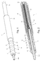
- a multipole probe 1 of a medical device of the implantable type for example a pacemaker, defibrillator or resynchronizer.
- the probe 1 comprises a probe body 20 in which are arranged various connecting conductors extending, via a connection plug 10, between an electric pulse generator (not shown) and the poles of the probe 1 placed at the distal end of the body 20.
- various connecting conductors extending, via a connection plug 10, between an electric pulse generator (not shown) and the poles of the probe 1 placed at the distal end of the body 20.
- four connecting conductors are shown, including a hollow conductor 24, for example a spirally wound cable, electrically connected to an axial pin 104 providing axial electrical contact with the generator, and having at its center a light communicating with a corresponding light 14 Provided in the axial pin 104.
- This arrangement allows the introduction of a mandrel for guiding the probe by the practitioner at the time of implantation in the patient or for the passage of a fixing system of the probe by screw .
- the hollow conductor 24 is housed inside a flexible sheath 30 made of insulating material such as a silicone whose fatigue resistance properties are excellent.
- the sheath 30 is provided externally with a coating of low friction material, for example polyurethane.
- the sheath 30 contains, in the nonlimiting example of the Figure 2 , three other connecting conductors that are the son 21, 22, 23 whose proximal ends are respectively connected to three annular electrical contact zones 11, 12, 13 distributed axially along the connection plug.
- the latter is of the multipole cylindrical type, plug in a single gesture into a homologous cavity of the generator. This mode of plugging simultaneously ensures the electrical connection of the various electrodes located at the poles of the probe 1 to the corresponding terminals of the generator.
- Such a multipole connection plug is particularly described in the EP 1 641 084 A1 supra.
- Card 10 of Figures 1 and 2 form an "isodiameter" assembly, that is to say in which the annular electrical contact zones 11, 12, 13 and intersipating insulating zones 31, 32, 33, 34 separating alternately the contact zones have a cylindrical outer surface smooth.
- the zones 11, 12, 13 are formed by cylindrical conductive rings 101, 102, 103 to which the connecting wires 21, 22, 23 are connected in a manner to be explained later.
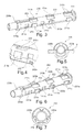
- connection plug 10 is organized around a central core 200 hollow hollow cylindrical general shape of which an embodiment is shown on the Figure 3 .
- the core 200 may advantageously be made by natural molding of an insulating material such as PEEK (polyetheretherketone) or Tecothane (registered trademark).
- Recesses generically noted 270 on the Figure 3 are provided on the body of the core 200 to simplify the demolding.
- the central core 200 is mainly characterized by the presence of coaxial lateral surfaces 211a, 211b, 212a, 212b, 213a, 213b, making it possible to obtain in a very simple and inexpensive manner a perfect coaxiality of the annular conductive rings 101, 102 , 103 when, when the plug 10 is mounted, these are placed on the lateral surfaces.
- the curvature of the lateral surfaces and the internal curvature of the rings must be identical.
- the Figure 4 is a more detailed view of the side surfaces 213a, 213b.
- the electrical connection between the connecting wires 21, 22, 23 and the annular conducting rings 101, 102, 103 can be made in the following manner.
- the connecting wires 21, 22, 23 are connected to intermediate conductive lugs, generically referenced 240, intended to be disposed inside housings 201, 202, 203 provided on the central core 200 and which can be seen more in detail about Figures 3, 4, 6 , 10 .
- the pods 240 are made of a biocompatible conductive material, for example 316 SS or MP35N stainless steel.
- the connecting wires 21, 22, 23 are preferably protected by an insulating protective sheath made of ethylene tetrafluoroethylene (ETFE) or polytetrafluoroethylene (PTFE), the wires being then stripped at their end connected to the intermediate lug 240.
- ETFE ethylene tetrafluoroethylene
- PTFE polytetrafluoroethylene
- the pods 240 can be machined.
- the outer curvature of the lug 240 must be compatible with the inner curvature of the rings.
- FIG. 8a, 8b Two versions of the 240 pod are proposed.
- the version of Figures 8a, 8b allows for direct alignment of the connecting wire 23 in the axis of the core 200.
- the intermediate lug 240 has an insertion groove 241.
- the son 21, 22 are placed transversely, which forces them to bend and fold to realign them in the axis of the core 200 and redirect them to the body 20 probe.
- the electrical connection between the wires 21, 22, 23 of connection and the intermediate lug 240 may be performed by laser welding, electric welding or any other technology capable of interconnecting two metal parts.
- the lugs 240 provided with their respective connecting wire are placed in the housings 201, 202, 203.
- the son 21, 22 which extend transversely to the axis of the core 200 are introduced into the slots formed on the side surfaces 211 b and 212a, then bent and folded so that they extend along the core 200, parallel to its axis, as shown in FIG. Figure 11 .
- This assembly operation can be performed, under binocular, using the holding tool shown in FIG. Figure 5 , where the central core 200 is placed in horizontal support on a recessed plate 2 by lateral wings 230a, 230b disposed at the end on the core.
- the core 200 is provided with means making it possible to hold the connection wires 21, 22 in the position they occupy on the ground.
- Figure 11 namely against the core and parallel to its axis.
- These holding means comprise, in general, longitudinal notches provided on the lateral centering surfaces.
- the sectional view of the Figure 12 shows longitudinal notches 253a, 253b formed in the lateral surfaces 213a, 213b centering, these notches being intended to apply and respectively maintain the son 21, 22 of connection against the central core 200.
- the connecting wire 22 is also held by the longitudinal notch 252a of the lateral surface 212a.
- second lateral centering surfaces are provided on the central core 200 to retain the son 21, 22 of connection in the longitudinal notches after they were introduced.
- the second lateral retaining surfaces of the wire 22 are referenced 261a, 262a.
- Other side surfaces of this type, not visible in the drawings, are present symmetrically to retain the wire 21 in the corresponding notches.
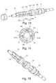
- the annular conductive rings 101, 102, 103 are then implemented by sliding them along the axis of the core 200 to bring them opposite the lug 240 to which they must be electrically connected.
- the Figure 14 shows in a sectional view the final disposition of the conductive ring 103 around the core 200.
- the central core 200 equipped with the set of conductive rings is represented on the Figure 15 .
- the rings 101, 102, 103 are then welded to the intermediate lugs 240 by laser, electrical or any other technology welding. This operation can be carried out ring after ring or on the three rings placed at first in a positioning tool.
- the welded connection must not affect the surface condition and cylindricity of the rings. For this, one can, for example, perform a weld on the side of the ring, inclining the assembly formed by the core 200, the son 21, 22, 23 connected to the lugs 240 and the rings 101,102,103.
- This step is a perfectly controlled and controllable process, made simplified by the central core 200 which partly plays the role of internal tooling.
- the bushings have an outside diameter given by ISO 27 186. Their positioning is essential, as is their coaxiality. As already mentioned, the coaxiality is obtained thanks to the lateral centering surfaces on which the rings come to bear. As for the longitudinal positioning, it can be provided by shoulders 221a, 221b, 222a, 222b, 223a, 223b carried respectively by the side surfaces 211a, 211b, 212a, 212b, 213a, 2123b that can be seen on the Figure 6 and against which the rings 101, 102, 102 abut.
- the central core 200 has a longitudinal flat 270, shown in FIG. Figure 7 allowing an introduction of the conductive rings on the lateral centering surfaces by reversible elastic deformation.
- a conductive ring such as the ring 101 can in this way be brought into position by successively crossing the shoulders 223a, 223b, then the shoulders 222a, 222b.
- the last step is to fill the spaces 111, 112, 113, 114 of the Figure 2 existing between the rings 101, 102, 103 in order to achieve the interspaced insulating zones 31, 32, 33, 34 alternately separating the contact zones 11, 12, 13 shown in FIG. Figure 1 .
- the connection plug is perfectly isodiameter in accordance with the ISO 27 186, and that it ensures the tightness of the system, which results, as we have seen above, the quality of the contact of the plug 10 with seals arranged in the cavity of the generator provided to receive the card.
- the filling of the spaces 111, 112, 113, 114 can be made, for example, by over-molding or injection of glue or plastic, or any other insulating material.
- the Figures 17 and 18 show respectively a section of the connection plug 10 through the contact zone 13 and a section through the insulating zone 33 after overmolding with an insulating material 280.
- the desired isodiameter for the plug 10 is obtained by a stack of insulating rings, such as those referenced 121, 122 in the above-mentioned figure, and of conductive rings, the coaxiality of all the rings and rings being provided by the lateral centering surfaces described above, the connection between a conductive ring and a subset formed by a connecting wire and the corresponding lug being made before each insertion of an insulating ring.
- the second variant of the Figure 20 uses binomials consisting of an insulating ring overmolded on a conductive ring, such as the pairs of ring 121 / ring 101 and ring 122 / ring 102, each pair being connected by the conductive ring to a subset connecting wire / pod before the introduction of a new pair.
- the invention not only greatly simplifies the assembly of a multi-pin probe connection plug, but also to have a visual control at each step of the assembly. The operator therefore has better control at each stage of the process.
- connection plug according to the invention can both be made directly on an existing probe body or be connected to the posterior probe. This allows the need to subcontract the manufacture of the plug and adapt it to any probe body.
Landscapes
- Health & Medical Sciences (AREA)
- Engineering & Computer Science (AREA)
- Radiology & Medical Imaging (AREA)
- Heart & Thoracic Surgery (AREA)
- Biomedical Technology (AREA)
- Nuclear Medicine, Radiotherapy & Molecular Imaging (AREA)
- Cardiology (AREA)
- Life Sciences & Earth Sciences (AREA)
- Animal Behavior & Ethology (AREA)
- General Health & Medical Sciences (AREA)
- Public Health (AREA)
- Veterinary Medicine (AREA)
- Manufacturing & Machinery (AREA)
- Electrotherapy Devices (AREA)
- Coupling Device And Connection With Printed Circuit (AREA)
Applications Claiming Priority (1)
| Application Number | Priority Date | Filing Date | Title |
|---|---|---|---|
| FR1152166 | 2011-03-16 |
Publications (3)
| Publication Number | Publication Date |
|---|---|
| EP2500998A2 true EP2500998A2 (de) | 2012-09-19 |
| EP2500998A3 EP2500998A3 (de) | 2013-10-09 |
| EP2500998B1 EP2500998B1 (de) | 2014-06-11 |
Family
ID=45531820
Family Applications (1)
| Application Number | Title | Priority Date | Filing Date |
|---|---|---|---|
| EP12153640.3A Active EP2500998B1 (de) | 2011-03-16 | 2012-02-02 | Elektrischer Anschlussstift für multipolare Sonde einer aktiven implantierbaren medizinischen Vorrichtung |
Country Status (2)
| Country | Link |
|---|---|
| US (2) | US8641436B2 (de) |
| EP (1) | EP2500998B1 (de) |
Cited By (2)
| Publication number | Priority date | Publication date | Assignee | Title |
|---|---|---|---|---|
| WO2014053147A1 (en) * | 2012-10-01 | 2014-04-10 | Tyco Electronics Nederland B.V. | An electrical plug, an electrical jack, a jack and plug system and a method for producing an electrical plug |
| CN111790008A (zh) * | 2020-08-11 | 2020-10-20 | 广东工业大学 | 一种导电高分子基可降解心脏起搏器连接线及其制备方法 |
Families Citing this family (10)
| Publication number | Priority date | Publication date | Assignee | Title |
|---|---|---|---|---|
| US9421362B2 (en) * | 2011-10-28 | 2016-08-23 | Medtronic, Inc. | Modular lead end |
| JP6086584B2 (ja) * | 2012-12-26 | 2017-03-01 | 株式会社ヨコオ | 電気コネクタ |
| US9209544B2 (en) * | 2013-01-31 | 2015-12-08 | Heraeus Precious Metals Gmbh & Co. Kg | Lead connector with distal frame and method of manufacture |
| WO2017044904A1 (en) | 2015-09-11 | 2017-03-16 | Nalu Medical, Inc. | Apparatus for peripheral or spinal stimulation |
| DE102018124307A1 (de) * | 2018-10-02 | 2020-04-02 | Biotronik Se & Co. Kg | Stecker mit einem umspritzten, nicht drehbaren Steckeranschluss und vier Anschlüssen, insbesondere IS4-/DF4-Stecker |
| US11458300B2 (en) | 2018-12-28 | 2022-10-04 | Heraeus Medical Components Llc | Overmolded segmented electrode |
| WO2021003439A1 (en) | 2019-07-02 | 2021-01-07 | Nalu Medical, Inc. | Stimulation apparatus |
| US12478789B2 (en) | 2020-07-27 | 2025-11-25 | Heraeus Medical Components Llc | Lead connector with assembly frame and method of manufacture |
| KR102663858B1 (ko) * | 2023-10-11 | 2024-05-10 | 오션스바이오 주식회사 | 결합성 및 안전성이 향상된 커넥터가 구비된 신경자극기 |
| WO2025237657A1 (en) * | 2024-05-16 | 2025-11-20 | Biotronik Se & Co. Kg | Safe design of a plastic tube for implantable electrodes through a functional geometry for the alignment of electrical connector contacts, as well as a safe assembly and alignment of electrical connector contacts |
Citations (2)
| Publication number | Priority date | Publication date | Assignee | Title |
|---|---|---|---|---|
| US20050221671A1 (en) | 2004-03-30 | 2005-10-06 | Medtronic, Inc. | Novel medical electrical connector |
| EP1641084A1 (de) | 2004-09-20 | 2006-03-29 | Ela Medical | Elektrischer Steckverbinder, insbesondere für einstückige Defibrillationssonde |
Family Cites Families (8)
| Publication number | Priority date | Publication date | Assignee | Title |
|---|---|---|---|---|
| US6854994B2 (en) * | 2001-04-19 | 2005-02-15 | Medtronic, Inc. | Medical electrical lead connector arrangement including anti-rotation means |
| US6755694B2 (en) * | 2001-04-19 | 2004-06-29 | Medtronic, Inc. | Lead upsizing sleeve |
| US8000802B2 (en) * | 2002-04-22 | 2011-08-16 | Medtronic, Inc. | Implantable lead with coplanar contact coupling |
| EP1794848A4 (de) * | 2004-08-27 | 2010-11-24 | Pmi Ind Inc | Flexibler verbinder für einen implantierbaren kabelbaum |
| US7083474B1 (en) * | 2004-12-08 | 2006-08-01 | Pacesetter, Inc. | System for lead retention and sealing of an implantable medical device |
| US7617006B2 (en) * | 2006-04-28 | 2009-11-10 | Medtronic, Inc. | Medical electrical lead for spinal cord stimulation |
| DE102008008927A1 (de) | 2008-02-13 | 2009-08-20 | Biotronik Crm Patent Ag | Elektrodenleitung und Anschlussstück für elektromedizinische Implantate |
| EP2262442B1 (de) * | 2008-04-11 | 2015-03-25 | BAL Seal Engineering | Steckerkartuschenstapel für eine elektrische übertragung |
-
2012
- 2012-02-02 EP EP12153640.3A patent/EP2500998B1/de active Active
- 2012-03-16 US US13/423,030 patent/US8641436B2/en not_active Expired - Fee Related
-
2013
- 2013-12-23 US US14/139,365 patent/US9227049B2/en active Active
Patent Citations (2)
| Publication number | Priority date | Publication date | Assignee | Title |
|---|---|---|---|---|
| US20050221671A1 (en) | 2004-03-30 | 2005-10-06 | Medtronic, Inc. | Novel medical electrical connector |
| EP1641084A1 (de) | 2004-09-20 | 2006-03-29 | Ela Medical | Elektrischer Steckverbinder, insbesondere für einstückige Defibrillationssonde |
Non-Patent Citations (1)
| Title |
|---|
| "dispositifs médicaux implan- tables actifs", 20 June 1990, CONSEIL DES COMMUNAUTÉS EUROPÉENNES |
Cited By (2)
| Publication number | Priority date | Publication date | Assignee | Title |
|---|---|---|---|---|
| WO2014053147A1 (en) * | 2012-10-01 | 2014-04-10 | Tyco Electronics Nederland B.V. | An electrical plug, an electrical jack, a jack and plug system and a method for producing an electrical plug |
| CN111790008A (zh) * | 2020-08-11 | 2020-10-20 | 广东工业大学 | 一种导电高分子基可降解心脏起搏器连接线及其制备方法 |
Also Published As
| Publication number | Publication date |
|---|---|
| US9227049B2 (en) | 2016-01-05 |
| US8641436B2 (en) | 2014-02-04 |
| EP2500998B1 (de) | 2014-06-11 |
| US20120322318A1 (en) | 2012-12-20 |
| EP2500998A3 (de) | 2013-10-09 |
| US20140107751A1 (en) | 2014-04-17 |
Similar Documents
| Publication | Publication Date | Title |
|---|---|---|
| EP2500998B1 (de) | Elektrischer Anschlussstift für multipolare Sonde einer aktiven implantierbaren medizinischen Vorrichtung | |
| EP1641084B1 (de) | Elektrischer Steckverbinder, insbesondere für einstückige Defibrillationssonde | |
| EP3173126B1 (de) | Implantierbare kapsel, insbesondere autonome kapsel zur stimulation der herzfunktion, und entsprechendes montageverfahren | |
| EP2544312B1 (de) | Anschluss für multipolare Sonde | |
| EP2647406B1 (de) | Elektrischer Anschlussstift für multipolare Sonde einer aktiven implantierbaren medizinischen Vorrichtung | |
| US8091226B2 (en) | Integrated header connector system | |
| US20100038132A1 (en) | Molded header connected to a medical device by lateral deformation of a sleeve/feedthrough pin sub-assembly | |
| EP2674190B1 (de) | Elektrodenstruktur für eine multipolare Detektions-/Stimulationsmikrosonde zur Implantation in ein Herz- oder Hirngefäß | |
| FR2662310A1 (fr) | Connecteur conducteur et ensemble de connexion d'electrodes a distance pour dispositif implantable, notamment pour stimulateur cardiaque. | |
| US9401562B2 (en) | Down the bore with open windows and manufacturing thereof | |
| EP2947485B1 (de) | Optische verbindungseinheit mit verbesserter führung der optischen kontaktenden, entsprechende stecker und verbindungsverfahren | |
| EP3075411B1 (de) | Multielektrodensonde mit multiplex-steuerung, insbesondere zur herzstimulation, und entsprechendes anschlussverfahren | |
| EP3252874B1 (de) | Muffe für buchsenkontakt, stecker der eine solche muffe verwendet, und ihr herstellungsverfahren | |
| FR2738406A1 (fr) | Prise electrique pourvue d'un etrier | |
| US11219773B2 (en) | Electrical connector cap for an implantable lead, implantable lead for use with said electrical connector cap, and implantable lead assembly | |
| EP3069755B1 (de) | Aktive implantierbare medizinische vorrichtung, die eine kapsel ohne anschluss umfasst, die permanent mit einer mikrosonde verbunden ist | |
| EP1557194B1 (de) | Einstückige Defibrillationssonde | |
| FR2563948A1 (fr) | Perfectionnements aux connecteurs electriques et aux procedes de fabrication de ceux-ci | |
| EP1036572A1 (de) | In Koronarvenen implantierbare Leitung zur Stimulation eines linken Herzvorhofs | |
| FR2988613A1 (fr) | Embase pour un generateur d'impulsions implantable et procede pour sa production | |
| FR2682821A1 (fr) | Connecteur biomedical implantable, et procede pour realiser une liaison electrique au moyen d'un tel connecteur. | |
| HK40008039A (en) | Implantable lead assembly comprising an electrical connector cap for an implantable lead and said lead | |
| HK40008039B (en) | Implantable lead assembly comprising an electrical connector cap for an implantable lead and said lead | |
| EP0561984A1 (de) | Verbindereinheit zwischen einem testgerät und einem testobjekt | |
| FR2630864A1 (fr) | Connecteur electrique |
Legal Events
| Date | Code | Title | Description |
|---|---|---|---|
| PUAI | Public reference made under article 153(3) epc to a published international application that has entered the european phase |
Free format text: ORIGINAL CODE: 0009012 |
|
| AK | Designated contracting states |
Kind code of ref document: A2 Designated state(s): AL AT BE BG CH CY CZ DE DK EE ES FI FR GB GR HR HU IE IS IT LI LT LU LV MC MK MT NL NO PL PT RO RS SE SI SK SM TR |
|
| AX | Request for extension of the european patent |
Extension state: BA ME |
|
| PUAL | Search report despatched |
Free format text: ORIGINAL CODE: 0009013 |
|
| AK | Designated contracting states |
Kind code of ref document: A3 Designated state(s): AL AT BE BG CH CY CZ DE DK EE ES FI FR GB GR HR HU IE IS IT LI LT LU LV MC MK MT NL NO PL PT RO RS SE SI SK SM TR |
|
| AX | Request for extension of the european patent |
Extension state: BA ME |
|
| RIC1 | Information provided on ipc code assigned before grant |
Ipc: H01R 24/58 20110101ALI20130830BHEP Ipc: H01R 107/00 20060101AFI20130830BHEP |
|
| 17P | Request for examination filed |
Effective date: 20131029 |
|
| RBV | Designated contracting states (corrected) |
Designated state(s): AL AT BE BG CH CY CZ DE DK EE ES FI FR GB GR HR HU IE IS IT LI LT LU LV MC MK MT NL NO PL PT RO RS SE SI SK SM TR |
|
| GRAP | Despatch of communication of intention to grant a patent |
Free format text: ORIGINAL CODE: EPIDOSNIGR1 |
|
| INTG | Intention to grant announced |
Effective date: 20131220 |
|
| GRAS | Grant fee paid |
Free format text: ORIGINAL CODE: EPIDOSNIGR3 |
|
| GRAA | (expected) grant |
Free format text: ORIGINAL CODE: 0009210 |
|
| AK | Designated contracting states |
Kind code of ref document: B1 Designated state(s): AL AT BE BG CH CY CZ DE DK EE ES FI FR GB GR HR HU IE IS IT LI LT LU LV MC MK MT NL NO PL PT RO RS SE SI SK SM TR |
|
| REG | Reference to a national code |
Ref country code: GB Ref legal event code: FG4D Free format text: NOT ENGLISH |
|
| REG | Reference to a national code |
Ref country code: CH Ref legal event code: EP |
|
| REG | Reference to a national code |
Ref country code: IE Ref legal event code: FG4D Free format text: LANGUAGE OF EP DOCUMENT: FRENCH |
|
| REG | Reference to a national code |
Ref country code: AT Ref legal event code: REF Ref document number: 672635 Country of ref document: AT Kind code of ref document: T Effective date: 20140715 |
|
| REG | Reference to a national code |
Ref country code: DE Ref legal event code: R096 Ref document number: 602012002005 Country of ref document: DE Effective date: 20140724 |
|
| PG25 | Lapsed in a contracting state [announced via postgrant information from national office to epo] |
Ref country code: LT Free format text: LAPSE BECAUSE OF FAILURE TO SUBMIT A TRANSLATION OF THE DESCRIPTION OR TO PAY THE FEE WITHIN THE PRESCRIBED TIME-LIMIT Effective date: 20140611 Ref country code: NO Free format text: LAPSE BECAUSE OF FAILURE TO SUBMIT A TRANSLATION OF THE DESCRIPTION OR TO PAY THE FEE WITHIN THE PRESCRIBED TIME-LIMIT Effective date: 20140911 Ref country code: GR Free format text: LAPSE BECAUSE OF FAILURE TO SUBMIT A TRANSLATION OF THE DESCRIPTION OR TO PAY THE FEE WITHIN THE PRESCRIBED TIME-LIMIT Effective date: 20140912 Ref country code: FI Free format text: LAPSE BECAUSE OF FAILURE TO SUBMIT A TRANSLATION OF THE DESCRIPTION OR TO PAY THE FEE WITHIN THE PRESCRIBED TIME-LIMIT Effective date: 20140611 |
|
| REG | Reference to a national code |
Ref country code: NL Ref legal event code: VDEP Effective date: 20140611 |
|
| REG | Reference to a national code |
Ref country code: AT Ref legal event code: MK05 Ref document number: 672635 Country of ref document: AT Kind code of ref document: T Effective date: 20140611 |
|
| REG | Reference to a national code |
Ref country code: LT Ref legal event code: MG4D |
|
| PG25 | Lapsed in a contracting state [announced via postgrant information from national office to epo] |
Ref country code: HR Free format text: LAPSE BECAUSE OF FAILURE TO SUBMIT A TRANSLATION OF THE DESCRIPTION OR TO PAY THE FEE WITHIN THE PRESCRIBED TIME-LIMIT Effective date: 20140611 Ref country code: LV Free format text: LAPSE BECAUSE OF FAILURE TO SUBMIT A TRANSLATION OF THE DESCRIPTION OR TO PAY THE FEE WITHIN THE PRESCRIBED TIME-LIMIT Effective date: 20140611 Ref country code: RS Free format text: LAPSE BECAUSE OF FAILURE TO SUBMIT A TRANSLATION OF THE DESCRIPTION OR TO PAY THE FEE WITHIN THE PRESCRIBED TIME-LIMIT Effective date: 20140611 Ref country code: SE Free format text: LAPSE BECAUSE OF FAILURE TO SUBMIT A TRANSLATION OF THE DESCRIPTION OR TO PAY THE FEE WITHIN THE PRESCRIBED TIME-LIMIT Effective date: 20140611 |
|
| PG25 | Lapsed in a contracting state [announced via postgrant information from national office to epo] |
Ref country code: CZ Free format text: LAPSE BECAUSE OF FAILURE TO SUBMIT A TRANSLATION OF THE DESCRIPTION OR TO PAY THE FEE WITHIN THE PRESCRIBED TIME-LIMIT Effective date: 20140611 Ref country code: EE Free format text: LAPSE BECAUSE OF FAILURE TO SUBMIT A TRANSLATION OF THE DESCRIPTION OR TO PAY THE FEE WITHIN THE PRESCRIBED TIME-LIMIT Effective date: 20140611 Ref country code: PT Free format text: LAPSE BECAUSE OF FAILURE TO SUBMIT A TRANSLATION OF THE DESCRIPTION OR TO PAY THE FEE WITHIN THE PRESCRIBED TIME-LIMIT Effective date: 20141013 Ref country code: SK Free format text: LAPSE BECAUSE OF FAILURE TO SUBMIT A TRANSLATION OF THE DESCRIPTION OR TO PAY THE FEE WITHIN THE PRESCRIBED TIME-LIMIT Effective date: 20140611 Ref country code: ES Free format text: LAPSE BECAUSE OF FAILURE TO SUBMIT A TRANSLATION OF THE DESCRIPTION OR TO PAY THE FEE WITHIN THE PRESCRIBED TIME-LIMIT Effective date: 20140611 Ref country code: RO Free format text: LAPSE BECAUSE OF FAILURE TO SUBMIT A TRANSLATION OF THE DESCRIPTION OR TO PAY THE FEE WITHIN THE PRESCRIBED TIME-LIMIT Effective date: 20140611 |
|
| PG25 | Lapsed in a contracting state [announced via postgrant information from national office to epo] |
Ref country code: PL Free format text: LAPSE BECAUSE OF FAILURE TO SUBMIT A TRANSLATION OF THE DESCRIPTION OR TO PAY THE FEE WITHIN THE PRESCRIBED TIME-LIMIT Effective date: 20140611 Ref country code: IS Free format text: LAPSE BECAUSE OF FAILURE TO SUBMIT A TRANSLATION OF THE DESCRIPTION OR TO PAY THE FEE WITHIN THE PRESCRIBED TIME-LIMIT Effective date: 20141011 Ref country code: AT Free format text: LAPSE BECAUSE OF FAILURE TO SUBMIT A TRANSLATION OF THE DESCRIPTION OR TO PAY THE FEE WITHIN THE PRESCRIBED TIME-LIMIT Effective date: 20140611 Ref country code: NL Free format text: LAPSE BECAUSE OF FAILURE TO SUBMIT A TRANSLATION OF THE DESCRIPTION OR TO PAY THE FEE WITHIN THE PRESCRIBED TIME-LIMIT Effective date: 20140611 |
|
| REG | Reference to a national code |
Ref country code: DE Ref legal event code: R097 Ref document number: 602012002005 Country of ref document: DE |
|
| PLBE | No opposition filed within time limit |
Free format text: ORIGINAL CODE: 0009261 |
|
| STAA | Information on the status of an ep patent application or granted ep patent |
Free format text: STATUS: NO OPPOSITION FILED WITHIN TIME LIMIT |
|
| PG25 | Lapsed in a contracting state [announced via postgrant information from national office to epo] |
Ref country code: DK Free format text: LAPSE BECAUSE OF FAILURE TO SUBMIT A TRANSLATION OF THE DESCRIPTION OR TO PAY THE FEE WITHIN THE PRESCRIBED TIME-LIMIT Effective date: 20140611 |
|
| 26N | No opposition filed |
Effective date: 20150312 |
|
| REG | Reference to a national code |
Ref country code: DE Ref legal event code: R097 Ref document number: 602012002005 Country of ref document: DE Effective date: 20150312 |
|
| PG25 | Lapsed in a contracting state [announced via postgrant information from national office to epo] |
Ref country code: BE Free format text: LAPSE BECAUSE OF NON-PAYMENT OF DUE FEES Effective date: 20150228 |
|
| PG25 | Lapsed in a contracting state [announced via postgrant information from national office to epo] |
Ref country code: SI Free format text: LAPSE BECAUSE OF FAILURE TO SUBMIT A TRANSLATION OF THE DESCRIPTION OR TO PAY THE FEE WITHIN THE PRESCRIBED TIME-LIMIT Effective date: 20140611 |
|
| PG25 | Lapsed in a contracting state [announced via postgrant information from national office to epo] |
Ref country code: LU Free format text: LAPSE BECAUSE OF FAILURE TO SUBMIT A TRANSLATION OF THE DESCRIPTION OR TO PAY THE FEE WITHIN THE PRESCRIBED TIME-LIMIT Effective date: 20150202 |
|
| REG | Reference to a national code |
Ref country code: CH Ref legal event code: PL |
|
| PG25 | Lapsed in a contracting state [announced via postgrant information from national office to epo] |
Ref country code: LI Free format text: LAPSE BECAUSE OF NON-PAYMENT OF DUE FEES Effective date: 20150228 Ref country code: CH Free format text: LAPSE BECAUSE OF NON-PAYMENT OF DUE FEES Effective date: 20150228 Ref country code: MC Free format text: LAPSE BECAUSE OF FAILURE TO SUBMIT A TRANSLATION OF THE DESCRIPTION OR TO PAY THE FEE WITHIN THE PRESCRIBED TIME-LIMIT Effective date: 20140611 |
|
| REG | Reference to a national code |
Ref country code: IE Ref legal event code: MM4A |
|
| REG | Reference to a national code |
Ref country code: FR Ref legal event code: PLFP Year of fee payment: 5 |
|
| PG25 | Lapsed in a contracting state [announced via postgrant information from national office to epo] |
Ref country code: IE Free format text: LAPSE BECAUSE OF NON-PAYMENT OF DUE FEES Effective date: 20150202 |
|
| PG25 | Lapsed in a contracting state [announced via postgrant information from national office to epo] |
Ref country code: MT Free format text: LAPSE BECAUSE OF FAILURE TO SUBMIT A TRANSLATION OF THE DESCRIPTION OR TO PAY THE FEE WITHIN THE PRESCRIBED TIME-LIMIT Effective date: 20140611 |
|
| REG | Reference to a national code |
Ref country code: FR Ref legal event code: PLFP Year of fee payment: 6 |
|
| PG25 | Lapsed in a contracting state [announced via postgrant information from national office to epo] |
Ref country code: SM Free format text: LAPSE BECAUSE OF FAILURE TO SUBMIT A TRANSLATION OF THE DESCRIPTION OR TO PAY THE FEE WITHIN THE PRESCRIBED TIME-LIMIT Effective date: 20140611 Ref country code: BG Free format text: LAPSE BECAUSE OF FAILURE TO SUBMIT A TRANSLATION OF THE DESCRIPTION OR TO PAY THE FEE WITHIN THE PRESCRIBED TIME-LIMIT Effective date: 20140611 Ref country code: HU Free format text: LAPSE BECAUSE OF FAILURE TO SUBMIT A TRANSLATION OF THE DESCRIPTION OR TO PAY THE FEE WITHIN THE PRESCRIBED TIME-LIMIT; INVALID AB INITIO Effective date: 20120202 |
|
| PG25 | Lapsed in a contracting state [announced via postgrant information from national office to epo] |
Ref country code: CY Free format text: LAPSE BECAUSE OF FAILURE TO SUBMIT A TRANSLATION OF THE DESCRIPTION OR TO PAY THE FEE WITHIN THE PRESCRIBED TIME-LIMIT Effective date: 20140611 |
|
| PG25 | Lapsed in a contracting state [announced via postgrant information from national office to epo] |
Ref country code: TR Free format text: LAPSE BECAUSE OF FAILURE TO SUBMIT A TRANSLATION OF THE DESCRIPTION OR TO PAY THE FEE WITHIN THE PRESCRIBED TIME-LIMIT Effective date: 20140611 |
|
| REG | Reference to a national code |
Ref country code: FR Ref legal event code: PLFP Year of fee payment: 7 |
|
| PG25 | Lapsed in a contracting state [announced via postgrant information from national office to epo] |
Ref country code: MK Free format text: LAPSE BECAUSE OF FAILURE TO SUBMIT A TRANSLATION OF THE DESCRIPTION OR TO PAY THE FEE WITHIN THE PRESCRIBED TIME-LIMIT Effective date: 20140611 |
|
| PG25 | Lapsed in a contracting state [announced via postgrant information from national office to epo] |
Ref country code: AL Free format text: LAPSE BECAUSE OF FAILURE TO SUBMIT A TRANSLATION OF THE DESCRIPTION OR TO PAY THE FEE WITHIN THE PRESCRIBED TIME-LIMIT Effective date: 20140611 |
|
| P01 | Opt-out of the competence of the unified patent court (upc) registered |
Effective date: 20230714 |
|
| REG | Reference to a national code |
Ref country code: DE Ref legal event code: R082 Ref document number: 602012002005 Country of ref document: DE Representative=s name: GULDE & PARTNER PATENT- UND RECHTSANWALTSKANZL, DE |
|
| PGFP | Annual fee paid to national office [announced via postgrant information from national office to epo] |
Ref country code: GB Payment date: 20260219 Year of fee payment: 15 |
|
| PGFP | Annual fee paid to national office [announced via postgrant information from national office to epo] |
Ref country code: DE Payment date: 20260206 Year of fee payment: 15 |
|
| PGFP | Annual fee paid to national office [announced via postgrant information from national office to epo] |
Ref country code: IT Payment date: 20260210 Year of fee payment: 15 |
|
| PGFP | Annual fee paid to national office [announced via postgrant information from national office to epo] |
Ref country code: FR Payment date: 20260227 Year of fee payment: 15 |