EP2647406B1 - Elektrischer Anschlussstift für multipolare Sonde einer aktiven implantierbaren medizinischen Vorrichtung - Google Patents
Elektrischer Anschlussstift für multipolare Sonde einer aktiven implantierbaren medizinischen Vorrichtung Download PDFInfo
- Publication number
- EP2647406B1 EP2647406B1 EP12192673.7A EP12192673A EP2647406B1 EP 2647406 B1 EP2647406 B1 EP 2647406B1 EP 12192673 A EP12192673 A EP 12192673A EP 2647406 B1 EP2647406 B1 EP 2647406B1
- Authority
- EP
- European Patent Office
- Prior art keywords
- pin
- plug
- plug body
- sleeve
- rod
- Prior art date
- Legal status (The legal status is an assumption and is not a legal conclusion. Google has not performed a legal analysis and makes no representation as to the accuracy of the status listed.)
- Active
Links
Images
Classifications
-
- H—ELECTRICITY
- H01—ELECTRIC ELEMENTS
- H01R—ELECTRICALLY-CONDUCTIVE CONNECTIONS; STRUCTURAL ASSOCIATIONS OF A PLURALITY OF MUTUALLY-INSULATED ELECTRICAL CONNECTING ELEMENTS; COUPLING DEVICES; CURRENT COLLECTORS
- H01R13/00—Details of coupling devices of the kinds covered by groups H01R12/70 or H01R24/00 - H01R33/00
- H01R13/58—Means for relieving strain on wire connection, e.g. cord grip, for avoiding loosening of connections between wires and terminals within a coupling device terminating a cable
-
- A—HUMAN NECESSITIES
- A61—MEDICAL OR VETERINARY SCIENCE; HYGIENE
- A61N—ELECTROTHERAPY; MAGNETOTHERAPY; RADIATION THERAPY; ULTRASOUND THERAPY
- A61N1/00—Electrotherapy; Circuits therefor
- A61N1/18—Applying electric currents by contact electrodes
- A61N1/32—Applying electric currents by contact electrodes alternating or intermittent currents
- A61N1/36—Applying electric currents by contact electrodes alternating or intermittent currents for stimulation
- A61N1/372—Arrangements in connection with the implantation of stimulators
- A61N1/375—Constructional arrangements, e.g. casings
- A61N1/3752—Details of casing-lead connections
-
- H—ELECTRICITY
- H01—ELECTRIC ELEMENTS
- H01R—ELECTRICALLY-CONDUCTIVE CONNECTIONS; STRUCTURAL ASSOCIATIONS OF A PLURALITY OF MUTUALLY-INSULATED ELECTRICAL CONNECTING ELEMENTS; COUPLING DEVICES; CURRENT COLLECTORS
- H01R13/00—Details of coupling devices of the kinds covered by groups H01R12/70 or H01R24/00 - H01R33/00
- H01R13/40—Securing contact members in or to a base or case; Insulating of contact members
- H01R13/405—Securing in non-demountable manner, e.g. moulding, riveting
- H01R13/41—Securing in non-demountable manner, e.g. moulding, riveting by frictional grip in grommet, panel or base
-
- H—ELECTRICITY
- H01—ELECTRIC ELEMENTS
- H01R—ELECTRICALLY-CONDUCTIVE CONNECTIONS; STRUCTURAL ASSOCIATIONS OF A PLURALITY OF MUTUALLY-INSULATED ELECTRICAL CONNECTING ELEMENTS; COUPLING DEVICES; CURRENT COLLECTORS
- H01R24/00—Two-part coupling devices, or either of their cooperating parts, characterised by their overall structure
- H01R24/58—Contacts spaced along longitudinal axis of engagement
-
- H—ELECTRICITY
- H01—ELECTRIC ELEMENTS
- H01R—ELECTRICALLY-CONDUCTIVE CONNECTIONS; STRUCTURAL ASSOCIATIONS OF A PLURALITY OF MUTUALLY-INSULATED ELECTRICAL CONNECTING ELEMENTS; COUPLING DEVICES; CURRENT COLLECTORS
- H01R43/00—Apparatus or processes specially adapted for manufacturing, assembling, maintaining, or repairing of line connectors or current collectors or for joining electric conductors
- H01R43/26—Apparatus or processes specially adapted for manufacturing, assembling, maintaining, or repairing of line connectors or current collectors or for joining electric conductors for engaging or disengaging the two parts of a coupling device
-
- H—ELECTRICITY
- H01—ELECTRIC ELEMENTS
- H01R—ELECTRICALLY-CONDUCTIVE CONNECTIONS; STRUCTURAL ASSOCIATIONS OF A PLURALITY OF MUTUALLY-INSULATED ELECTRICAL CONNECTING ELEMENTS; COUPLING DEVICES; CURRENT COLLECTORS
- H01R13/00—Details of coupling devices of the kinds covered by groups H01R12/70 or H01R24/00 - H01R33/00
- H01R13/46—Bases; Cases
- H01R13/502—Bases; Cases composed of different pieces
-
- H—ELECTRICITY
- H01—ELECTRIC ELEMENTS
- H01R—ELECTRICALLY-CONDUCTIVE CONNECTIONS; STRUCTURAL ASSOCIATIONS OF A PLURALITY OF MUTUALLY-INSULATED ELECTRICAL CONNECTING ELEMENTS; COUPLING DEVICES; CURRENT COLLECTORS
- H01R2105/00—Three poles
-
- Y—GENERAL TAGGING OF NEW TECHNOLOGICAL DEVELOPMENTS; GENERAL TAGGING OF CROSS-SECTIONAL TECHNOLOGIES SPANNING OVER SEVERAL SECTIONS OF THE IPC; TECHNICAL SUBJECTS COVERED BY FORMER USPC CROSS-REFERENCE ART COLLECTIONS [XRACs] AND DIGESTS
- Y10—TECHNICAL SUBJECTS COVERED BY FORMER USPC
- Y10T—TECHNICAL SUBJECTS COVERED BY FORMER US CLASSIFICATION
- Y10T29/00—Metal working
- Y10T29/49—Method of mechanical manufacture
- Y10T29/49002—Electrical device making
- Y10T29/49117—Conductor or circuit manufacturing
- Y10T29/49204—Contact or terminal manufacturing
- Y10T29/49208—Contact or terminal manufacturing by assembling plural parts
Definitions
- the invention relates generally to "active implantable medical devices" as defined by Council Directive 90/385 / EEC of 20 June 1990.
- This definition includes, in particular, cardiac implants responsible for monitoring cardiac activity and generating pacing, defibrillation and / or resynchronization pulses in the event of a rhythm disorder detected by the device. It also includes neurological devices, cochlear implants, diffusion pumps for medical substances, implanted biological sensors, etc.
- These devices comprise a housing generally designated “generator”, electrically and mechanically connected to one or more “probes” provided with (s) electrodes intended to come into contact with the tissues on which it is desired to apply stimulation pulses and / or collect an electrical signal: myocardium, nerve, muscle ...
- IS-1 and IS-4" standards define a certain number of dimensional and electrical characteristics relating to stimulation pulse delivery (or resynchronization) probes.
- DF-1 and DF-4 standards define the dimensional and electrical characteristics of the system. connection.
- the invention more particularly relates to a multi-pin electrical connection plug for such a probe, for example a monocorps probe provided with both stimulation and shock electrodes.
- connection plug The EP 1 641 084 A1 (ELA Medical) describes an example of such a four-pole connection plug. More specifically, this known connection plug is of the isodiameter type, having at one of its ends an axial electrical contact pin and, on the same body of the plug, three annular electrical contact zones formed by conductive cylindrical rings. The annular electrical contact zones are alternately separated by intersecting insulating cylindrical zones in order to electrically isolate the electrical contact zones from each other.
- connection plug into the cavity of the connector head of the generator in a single gesture, simultaneously making all the necessary electrical connections between the generator and the poles of the probe.
- These probes are used in particular to allow the drive from the proximal end (where the plug is located) of a deployment mechanism of an anchoring screw at the distal end, by a so - called pin-driven manipulation , where the surgeon holds with one hand the proximal end of the probe body with its connector, and rotates with the other hand the pin ( pin ) protruding from this plug. Torque applied to the spindle is transmitted through the inner conductor to the deployment and drive mechanism of the anchor screw, thereby controlling penetration of the anchor screw into the cardiac wall.
- a pin-driven probe structure is for example described in US 7,241,180 B1 and US 2010/0211144 A1 .
- the US 2010/0211144 A1 proposes to achieve a mounting assembly of the spindle having two concentric elements, with a ring-shaped piece mounted around the shaft of the spindle (this part can be used as a bearing, if the spindle is rotatable) and other hand a circumferential collar surrounding the ring at its periphery and playing a coupler role with the plug body, where this collar is encapsulated or screwed during manufacture.
- This configuration allows to spare if necessary a degree of freedom in rotation between pin and plug body.
- it leads to a relatively complex and expensive manufacturing, requiring the production of parts with very strict tolerances to be able to meet the dimensional constraints imposed.
- the object of the invention is to provide a solution to these various problems, thanks to a simplified plug configuration, achievable by a simple manufacturing process and therefore inexpensive, while respecting the very strict constraints of dimensional tolerances and seal. It will be seen in particular that the industrial implementation of the plug according to the invention is facilitated by the use of very simple form parts (thus easy and inexpensive to machine) and by reducing the number of these parts to assemble.
- the particular configuration of the plug of the invention ensures a very good protection of the connection between the central pin and the inner conductor to which the latter is welded, with respect to the various stresses and the risks of breaking of this fatigue connection of the materials at the pin-driver interface.
- the invention is particularly advantageous in the context of a pin-driven type probe with moving axial spindle, it will be noted that it can be applied to both fixed axial pin probes, taking into account the advantages mentioned above, especially ease of industrial implementation.
- the invention proposes an electrical connection plug for a multipolar probe of an active implantable medical device as disclosed, for example, by the US 7,241,180 B1 mentioned above, ie a form having a cylindrical outer surface carrying a plurality of axially distributed annular contacts and bearing at its free end an axial contact, which plug comprises: an axial end pin made of conductive material, forming at its free end said axial contact and having at its end opposite end a mounting rod adapted to be connected to an inner central conductor of the probe; a plug body of insulating material, comprising a central bore housing the center conductor and the pin shaft and carrying on its outer surface the annular contacts, the plug body also housing connecting conductors to the respective annular contacts; and means for connecting the pin to the plug body, forming a bonding interface between the pin shaft and the inner wall of the bore of the plug body in the vicinity of its outlet.
- the means for connecting the pin to the plug body comprise: a holding bushing mounted on the spindle rod so that, axially, the end face of this bushing bears against a collar formed on the rod and, radially, the outer surface of this sleeve comes into direct contact with the inner wall of the bore of the plug body at the outlet thereof; a locking ring, secured to the pin of the spindle so that, axially, the holding sleeve is clamped between the neck of the rod and the locking ring, if necessary leaving a degree of freedom in rotation between sleeve and pin; and means for direct attachment of the sleeve to the plug body at the point of contact with the inner wall of the bore.
- the means for direct fastening of the sleeve to the plug body comprise a snap connection with notches cooperating with a homologous groove, which connection may optionally be subsequently welded or glued.
- the plug may further comprise a seal mounted on the pin of the pin so as to be caught axially between the locking ring and a shoulder vis-à-vis the central bore of the plug body.
- the sleeve is preferably made of a biocompatible polymer material.
- a multipolar "isodiameter" probe is shown, in this example a probe conforming to the IS-4 / DF-4 (ISO 27186) standard.
- This probe end is in the form of a plug to be inserted into a connector head of an implanted generator, for example a pacemaker, defibrillator and / or resynchronizer.
- an implanted generator for example a pacemaker, defibrillator and / or resynchronizer.
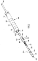
- the Figure 1 is an exploded view of this sheet showing the various elements that constitute it.
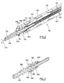
- the form is represented in assembled form, as it appears at the end of the manufacturing process, while the Figure 2 shows in more detail the internal structure of this same sheet with the configuration of the different parts in their final state, assembled.
- This plug comprises a plug body 100 carrying a plurality of annular contacts 110, 120, 130, the rest of the plug body being constituted by a piece 140 of insulating material.
- the assembly is of the "isodiameter" type, that is to say that it is in the form of a smooth cylindrical body, devoid of reliefs.
- This plug body 100 carries proximal side (left in the figure) an end axial pin 200 of conductive material, whose free end emerging proximal side of the plug is an axial contact 210.
- the plug is a quadrupole plug (three annular contacts and one axial contact).
- This configuration corresponds for example to a bipolar probe allowing on the one hand (according to the IS-4 standard) the collection of depolarization waves and the application of stimulation pulses between the axial electrode 210 and the annular electrode 110, and on the other hand (according to the DF-4 standard) the application of a defibrillation shock between the two annular electrodes 120 and 130.
- the electrodes 120 and / or 130, or other additional annular electrodes may be used for connection to a power supply and / or circuit control line embedded in the probe, a sensor located at the end of the probe such as an endocardial acceleration sensor, etc.
- the configuration illustrated is of course not limiting, and the invention is applicable to a plug carrying any number of annular contacts.
- the pin 200 has in its center a light 220 allowing the introduction of a mandrel for guiding the probe by the practitioner at the time of implantation in the patient.
- the pin 200 comprises a cylindrical mounting rod 230, whose end located distal side (right in the figure) is intended to be connected to an inner core conductor 240, at the proximal end 242 thereof.
- This conductor 240 is housed in a central bore 142 ( Figure 2 ) of the plug body 100, and it can optionally be rotatable within this bore.
- the conductor 240 is coated along its length with a sheath 250 of low friction material, for example PTFE.
- the central bore 142 opens on the proximal side at 144.
- the pin 200 is a one-piece element made of a conductive material, for example an MP35N stainless steel.
- the plug body 100 is made, as regards the insulating part 140, into a biocompatible polymer, for example an insulating material such as a polyetheretherketone (PEEK) or a thermoplastic aromatic polyurethane such as Tecothane (registered trademark), which are thermoplastic materials which can be easily overmolded with the annular contacts 110, 120, 130 (which are for example made of stainless steel MP35N), as well as with the connecting conductors to these rings, such as the conductor 132 visible Figure 2 .
- PEEK polyetheretherketone
- Tecothane registered trademark
- the link between the pin 200 and the plug body 100 is formed by an assembly consisting of a retaining sleeve 300 clamped between a collar 260 formed on the pin 200 between the free end 210 and the mounting rod 230, proximal side. , and a locking ring 400, distal side.
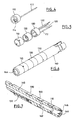
- These elements are represented in isolation Figure 3 mounted on pin 200.
- This configuration ensures virtually zero axial clearance between bushing 300 and the assembly formed by pin 200 and bushing 400 (bushing 400 being attached to spindle 200 so as to constitute a one-piece assembly with the latter), while providing, if necessary, a degree of freedom in rotation between pin 200 and ring 300, for a pin-driven type of probe (this possibility of rotation is illustrated by the arrow 270).
- the bushing 300 has a proximal shoulder 310 defining, distal side, a face 320 capable of coming into contact with a homologous shoulder 146 located at the outlet 144 of the internal lumen of the plug body, and proximal side a face 330 abutting against the collar 260 of the spindle 200.
- the sleeve 300 is directly secured to the plug body 100 at the point of its contact with the inner wall of the internal bore, which allows a very simple mounting ensuring compliance with dimensional tolerances and a perfect seal with in particular the central bore 142 of the plug body 100.
- sealing particularly in the case of a pin-driven type sensor , it is also possible to provide a sealing O-ring 500 (FIG. Figure 2 ), for example silicone, compressed between the distal face of the ring 400 and a shoulder 148 vis-à-vis the central bore 142 of the plug body.
- the ring 400 is made of a material that can be easily secured to the mounting plug 230 of the pin 200, for example stainless steel MP35N.
- the holding sleeve 300 for its part, is made of a material that can be easily secured to the insulating portion 140 of the plug body, for example PEEK or Tecothane.
- the first step is the realization of the plug body 100, overmolded with its annular contacts 110, 120, 130.
- the annular contacts are prepared in isolation, as illustrated Figure 4 , for example by welding inside a contact 110 a lug 114 on which is welded or crimped the corresponding conductor 112 (the contact 110 and the lug 114 may be, alternatively, two parts of one and the same piece) .
- the various annular contacts 110, 120, 130 provided with their respective conductors 112, 122, 132 are then positioned relative to each other according to the configuration that they must have on the plug body in its final state.
- the insulating part 140 of the plug body made of biocompatible polymer material, is overmolded with the contacts 110, 120, 130 as illustrated in FIG. 6, providing a central lumen 142.
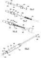
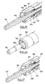
- the first step ( Figure 8 ) is to thread the holding sleeve 300 on the mounting rod 230 of the spindle 200, until the face 330 of this sleeve abuts against the collar 260.
- the locking ring 400 is then also threaded on the mounting rod 230 so as to press the ring 300 against the collar 260, then this ring is secured to the pin 200 in this position for example by laser welding (as illustrated in 410, Figure 9 ), gluing, screwing, crimping or other suitable securing means.
- the next step, illustrated Figure 9 consists, after having placed the optional seal 500 around the mounting rod 230 and against the ring 400, to weld the end 242 of the axial conductor 240 to the end of the mounting rod 230, for example by laser welding ( as shown in 270, Figure 10).
- the resulting subset is illustrated Figure 10 in its final state.
- the next step, illustrated Figure 10 consists in introducing (arrow 280) this subassembly into the inner lumen of the plug body 100 from the proximal end of the latter, until the face 320 of the retaining sleeve 300 proximal side comes into position. stop against the plastic material of the body 140.
- the axial conductor 240 is prepared at the same time as the plug body 100, and constitutes with it a clean set.
- the axial conductor 240 of the latter is then mounted on another assembly, which is that illustrated Figure 8 , comprising the spindle 200, the retaining sleeve 300 and the locking ring 400 assembled together, with possible insertion of the seal 500 on the spindle rod before welding.
- the axial conductor 240 is welded to the mounting rod 230, and the resulting configuration is then identical to that described above and illustrated. Figure 10 .
- the Figure 11 illustrates the final state of the form obtained after execution of the various process steps of the Figures 4 to 10 .
- the sleeve 300 and the polymer 140 of the plug body are made of identical or comparable materials (two biocompatible polymers), it is easy to achieve such a connection with all the guarantees of respect for dimensional tolerances and sealing, without implementation of particularly complex manufacturing techniques.
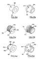
- the Figures 12a and 12b correspond to a first embodiment, which is the one illustrated on the Figures 1 to 11 as just described, with a smooth outer surface 350 inserted into a recess of conjugate shape located at the outlet of the plug body, where the ring is glued or welded.
- FIG. 13a and 13b A second embodiment is illustrated Figures 13a and 13b as well as in assembled form on Figures 15 and 16 .
- the outer surface of the bushing 300 is provided with a thread 360 cooperating with a homologous tapping 150 formed in the plug body 100 (FIG. Figure 15 ).
- a suitable tool for performing the screwing of the sleeve 300 in the plug body it may be further provided to glue or weld together.
- the outer surface 350 of the sleeve 300 is provided with notches 380 cooperating with a homologous groove 160 (FIG. 17) formed in the plug body. This allows an introduction of the sleeve 300 by snapping directly into the plug body, with if necessary bonding or welding of these two elements to strengthen the connection between them.
Landscapes
- Health & Medical Sciences (AREA)
- Engineering & Computer Science (AREA)
- Biomedical Technology (AREA)
- Nuclear Medicine, Radiotherapy & Molecular Imaging (AREA)
- Radiology & Medical Imaging (AREA)
- Life Sciences & Earth Sciences (AREA)
- Animal Behavior & Ethology (AREA)
- General Health & Medical Sciences (AREA)
- Public Health (AREA)
- Veterinary Medicine (AREA)
- Manufacturing & Machinery (AREA)
- Electrotherapy Devices (AREA)
Claims (4)
- Elektrischer Anschlussstecker für eine mehrpolige Sonde einer aktiven implantierbaren medizinischen Vorrichtung, wobei dieser Stecker eine zylindrische Außenfläche aufweist, die eine Vielzahl von axial verteilten Ringkontakten (110, 120, 130) trägt, und an seinem freien Ende einen axialen Kontakt (210) trägt, wobei dieser Stecker enthält:- einen axialen Endstift (200) aus leitendem Material, der an seinem freien Ende den axialen Kontakt (210) bildet und an seinem gegenüberliegenden Ende eine Montagestange (230) aufweist, die mit einem inneren zentralen Leiter (240) der Sonde verbunden werden kann;- einen Steckerkörper (140) aus Isoliermaterial, der eine zentrale Bohrung (142) enthält, die den zentralen Leiter und die Stange des Stifts aufnimmt, und an seiner Außenfläche die Ringkontakte (110, 120, 130) trägt, wobei der Steckerkörper ebenfalls Leiter (112, 122, 132) zur Verbindung mit den jeweiligen Ringkontakten aufnimmt; und- Einrichtungen zur Verbindung des Stifts mit dem Steckerkörper, die eine Verbindungsschnittstelle zwischen der Stange des Stifts und der Innenwand der Bohrung des Steckerkörpers in der Nähe ihrer Ausmündung formen,
wobei die Einrichtungen zur Verbindung des Stifts mit dem Steckerkörper enthalten:- eine Haltehülse (300), die so auf die Stange (230) des Stifts montiert ist, dass:· axial die Stirnseite (310) dieser Hülse gegen einen auf der Stange geformten Kragen (260) in Anlage kommt, und· radial die Außenfläche dieser Hülse in direkten Kontakt mit der Innenwand der Bohrung des Steckerkörpers (140) an deren Ausmündung kommt;- einen Arretierring (400), der fest mit der Stange (230) des Stifts verbunden ist, so dass die Haltehülse (300) sich axial zwischen dem Kragen der Stange und dem Arretierring eingeklemmt befindet, notfalls, indem ein Drehfreiheitsgrad zwischen Hülse und Stift gelassen wird; und- Einrichtungen zur direkten festen Verbindung der Hülse (300) mit dem Steckerkörper (140) an der Stelle ihres Kontakts mit der Innenwand der Bohrung,
dadurch gekennzeichnet, dass die Einrichtungen zur direkten festen Verbindung der Hülse mit dem Steckerkörper eine Einrastverbindung mit Rasten (380) enthalten, die mit einer entsprechenden Rille (160) zusammenwirken. - Anschlussstecker nach Anspruch 1, der außerdem eine Dichtung (500) enthält, die so auf die Stange des Stifts montiert ist, dass sie axial zwischen dem Arretierring (400) und einer gegenüberliegenden Schulter (148) der zentralen Bohrung (142) des Steckerkörpers eingeklemmt wird.
- Anschlussstecker nach Anspruch 1, wobei die Hülse (300) aus einem biokompatiblen Polymermaterial hergestellt ist.
- Anschlussstecker nach Anspruch 1, wobei die Einrastverbindung außerdem geschweißt oder geklebt ist.
Applications Claiming Priority (1)
| Application Number | Priority Date | Filing Date | Title |
|---|---|---|---|
| FR1253103 | 2012-04-04 |
Publications (2)
| Publication Number | Publication Date |
|---|---|
| EP2647406A1 EP2647406A1 (de) | 2013-10-09 |
| EP2647406B1 true EP2647406B1 (de) | 2014-10-29 |
Family
ID=47143779
Family Applications (1)
| Application Number | Title | Priority Date | Filing Date |
|---|---|---|---|
| EP12192673.7A Active EP2647406B1 (de) | 2012-04-04 | 2012-11-14 | Elektrischer Anschlussstift für multipolare Sonde einer aktiven implantierbaren medizinischen Vorrichtung |
Country Status (2)
| Country | Link |
|---|---|
| US (1) | US8911265B2 (de) |
| EP (1) | EP2647406B1 (de) |
Families Citing this family (9)
| Publication number | Priority date | Publication date | Assignee | Title |
|---|---|---|---|---|
| US9421362B2 (en) * | 2011-10-28 | 2016-08-23 | Medtronic, Inc. | Modular lead end |
| EP2876742A1 (de) * | 2013-11-21 | 2015-05-27 | Tyco Electronics Raychem GmbH | Stecker und Steckeranordnung mit einem Stecker |
| US9072909B1 (en) * | 2013-12-18 | 2015-07-07 | Medtronic, Inc. | Implantable medical electrical lead connectors, assemblies thereof, and methods of manufacture |
| US9101776B2 (en) * | 2013-12-18 | 2015-08-11 | Medtronic, Inc. | Implantable medical electrical lead connector assemblies and methods of manufacture |
| EP3459593B1 (de) * | 2017-09-20 | 2020-10-21 | Sorin CRM SAS | Implantierbare leitungsanordnung bestehend aus einer elektrische verbinderkappe für eine implantierbare leitung und der leitung |
| CN108211117B (zh) * | 2018-02-07 | 2024-04-26 | 宁波越凡医疗科技有限公司 | 一种具有按摩功能的止吐手环 |
| DE102018124307A1 (de) * | 2018-10-02 | 2020-04-02 | Biotronik Se & Co. Kg | Stecker mit einem umspritzten, nicht drehbaren Steckeranschluss und vier Anschlüssen, insbesondere IS4-/DF4-Stecker |
| US11331502B2 (en) | 2019-04-26 | 2022-05-17 | Medtronic, Inc. | Implantable medical leads and lead extensions having an encapsulation band |
| CN122422011A (zh) * | 2023-12-18 | 2026-07-17 | 索林Crm联合股份公司 | 用于操作导线装置的锁定装置 |
Family Cites Families (9)
| Publication number | Priority date | Publication date | Assignee | Title |
|---|---|---|---|---|
| US4898173A (en) * | 1988-04-22 | 1990-02-06 | Medtronic, Inc. | In-line pacemaker connector system |
| US6248080B1 (en) * | 1997-09-03 | 2001-06-19 | Medtronic, Inc. | Intracranial monitoring and therapy delivery control device, system and method |
| FR2875644B1 (fr) | 2004-09-20 | 2006-12-15 | Ela Medical Sa | Fiche de connexion electrique modulaire, notamment pour sonde de defibrillation monocorps |
| US7962213B2 (en) * | 2005-05-12 | 2011-06-14 | Cardiac Pacemakers, Inc. | Interconnected electrode assembly for a lead connector and method therefor |
| US7241180B1 (en) | 2006-01-31 | 2007-07-10 | Medtronic, Inc. | Medical electrical lead connector assembly |
| US8126557B2 (en) | 2009-02-13 | 2012-02-28 | Pacesetter, Inc. | Lead connector pin and body assembly and method of manufacture |
| US20110144722A1 (en) * | 2009-12-10 | 2011-06-16 | Pacesetter, Inc. | Mri-compatible implantable lead with improved lc resonant component |
| US8382529B2 (en) * | 2009-12-30 | 2013-02-26 | Cardiac Pacemakers, Inc. | Terminal connector assembly for a medical electrical lead |
| US8556664B2 (en) * | 2010-04-20 | 2013-10-15 | Apple Inc. | Plug assembly with core structural member |
-
2012
- 2012-11-14 EP EP12192673.7A patent/EP2647406B1/de active Active
-
2013
- 2013-04-04 US US13/857,033 patent/US8911265B2/en active Active
Also Published As
| Publication number | Publication date |
|---|---|
| EP2647406A1 (de) | 2013-10-09 |
| US20130267127A1 (en) | 2013-10-10 |
| US8911265B2 (en) | 2014-12-16 |
Similar Documents
| Publication | Publication Date | Title |
|---|---|---|
| EP2647406A1 (de) | Elektrischer Anschlussstift für multipolare Sonde einer aktiven implantierbaren medizinischen Vorrichtung | |
| EP2544312B1 (de) | Anschluss für multipolare Sonde | |
| EP2500998B1 (de) | Elektrischer Anschlussstift für multipolare Sonde einer aktiven implantierbaren medizinischen Vorrichtung | |
| EP3173126B1 (de) | Implantierbare kapsel, insbesondere autonome kapsel zur stimulation der herzfunktion, und entsprechendes montageverfahren | |
| EP1641084B1 (de) | Elektrischer Steckverbinder, insbesondere für einstückige Defibrillationssonde | |
| US7717754B2 (en) | Connector assembly with internal seals and manufacturing method | |
| CA2459335C (en) | Electronic lead for a medical implant device, method of making same, and method and apparatus for inserting same | |
| EP2674190B1 (de) | Elektrodenstruktur für eine multipolare Detektions-/Stimulationsmikrosonde zur Implantation in ein Herz- oder Hirngefäß | |
| US6327502B1 (en) | Implantable stimulator housing with electrode connector | |
| US20030036779A1 (en) | Multi-polar connector | |
| EP3075411B1 (de) | Multielektrodensonde mit multiplex-steuerung, insbesondere zur herzstimulation, und entsprechendes anschlussverfahren | |
| US20150306402A1 (en) | Down the bore with open windows and manufacturing thereof | |
| EP2664354A1 (de) | Ringelektrode zur Implantation in ein Herz- oder Hirngefäß und ein Verfahren zu deren Herstellung | |
| EP2384788B1 (de) | Schraubenloses Schnellverbindungssystem eines Sondenanschlusses an einen Generator eines implantierbaren Medizingeräts | |
| EP1177815A1 (de) | Aktive implantierbare medizinische Vorrichtung, insbesondere Herzschrittmacher, Defibrillator, und/oder Kardiovertierer, mit einem abnehmbaren Verbindungskopf | |
| EP2465425B1 (de) | Leitung für ein aktives implantierbares medizinisches Gerät, umfassend einen Chip, insbesondere zum Multiplexen | |
| US11219773B2 (en) | Electrical connector cap for an implantable lead, implantable lead for use with said electrical connector cap, and implantable lead assembly | |
| US20150165216A1 (en) | Implantable medical electrical lead connectors, assemblies thereof, and methods of manufacture | |
| EP2374498B1 (de) | Implantierbare medizinische Leitung und Herstellungsverfahren dafür | |
| EP1557194B1 (de) | Einstückige Defibrillationssonde | |
| FR3033705A1 (fr) | Dispositif medical implantable actif comprenant une capsule depourvue de connecteur, reliee de facon permanente a une microsonde | |
| FR3059476A1 (fr) | Dispositif de connexion electrique | |
| EP1036572B1 (de) | In Koronarvenen implantierbare Leitung zur Stimulation eines linken Herzvorhofs | |
| HK40008039B (en) | Implantable lead assembly comprising an electrical connector cap for an implantable lead and said lead |
Legal Events
| Date | Code | Title | Description |
|---|---|---|---|
| PUAI | Public reference made under article 153(3) epc to a published international application that has entered the european phase |
Free format text: ORIGINAL CODE: 0009012 |
|
| 17P | Request for examination filed |
Effective date: 20121114 |
|
| AK | Designated contracting states |
Kind code of ref document: A1 Designated state(s): AL AT BE BG CH CY CZ DE DK EE ES FI FR GB GR HR HU IE IS IT LI LT LU LV MC MK MT NL NO PL PT RO RS SE SI SK SM TR |
|
| AX | Request for extension of the european patent |
Extension state: BA ME |
|
| RBV | Designated contracting states (corrected) |
Designated state(s): AL AT BE BG CH CY CZ DE DK EE ES FI FR GB GR HR HU IE IS IT LI LT LU LV MC MK MT NL NO PL PT RO RS SE SI SK SM TR |
|
| RIN1 | Information on inventor provided before grant (corrected) |
Inventor name: VIATGE, HELENE Inventor name: DI MAIO, LUCIANO Inventor name: ROUSSIN, MYLENE |
|
| RIC1 | Information provided on ipc code assigned before grant |
Ipc: A61N 1/375 20060101AFI20131023BHEP Ipc: H01R 13/58 20060101ALI20131023BHEP Ipc: H01R 24/58 20110101ALI20131023BHEP Ipc: H01R 13/40 20060101ALI20131023BHEP Ipc: H01R 43/26 20060101ALI20131023BHEP Ipc: H01R 13/629 20060101ALI20131023BHEP |
|
| GRAP | Despatch of communication of intention to grant a patent |
Free format text: ORIGINAL CODE: EPIDOSNIGR1 |
|
| INTG | Intention to grant announced |
Effective date: 20140514 |
|
| GRAS | Grant fee paid |
Free format text: ORIGINAL CODE: EPIDOSNIGR3 |
|
| GRAA | (expected) grant |
Free format text: ORIGINAL CODE: 0009210 |
|
| AK | Designated contracting states |
Kind code of ref document: B1 Designated state(s): AL AT BE BG CH CY CZ DE DK EE ES FI FR GB GR HR HU IE IS IT LI LT LU LV MC MK MT NL NO PL PT RO RS SE SI SK SM TR |
|
| REG | Reference to a national code |
Ref country code: GB Ref legal event code: FG4D Free format text: NOT ENGLISH |
|
| REG | Reference to a national code |
Ref country code: CH Ref legal event code: EP |
|
| REG | Reference to a national code |
Ref country code: AT Ref legal event code: REF Ref document number: 693258 Country of ref document: AT Kind code of ref document: T Effective date: 20141115 |
|
| REG | Reference to a national code |
Ref country code: IE Ref legal event code: FG4D Free format text: LANGUAGE OF EP DOCUMENT: FRENCH |
|
| REG | Reference to a national code |
Ref country code: DE Ref legal event code: R096 Ref document number: 602012003569 Country of ref document: DE Effective date: 20141211 |
|
| REG | Reference to a national code |
Ref country code: AT Ref legal event code: MK05 Ref document number: 693258 Country of ref document: AT Kind code of ref document: T Effective date: 20141029 |
|
| REG | Reference to a national code |
Ref country code: NL Ref legal event code: VDEP Effective date: 20141029 |
|
| REG | Reference to a national code |
Ref country code: LT Ref legal event code: MG4D |
|
| PG25 | Lapsed in a contracting state [announced via postgrant information from national office to epo] |
Ref country code: LT Free format text: LAPSE BECAUSE OF FAILURE TO SUBMIT A TRANSLATION OF THE DESCRIPTION OR TO PAY THE FEE WITHIN THE PRESCRIBED TIME-LIMIT Effective date: 20141029 Ref country code: ES Free format text: LAPSE BECAUSE OF FAILURE TO SUBMIT A TRANSLATION OF THE DESCRIPTION OR TO PAY THE FEE WITHIN THE PRESCRIBED TIME-LIMIT Effective date: 20141029 Ref country code: FI Free format text: LAPSE BECAUSE OF FAILURE TO SUBMIT A TRANSLATION OF THE DESCRIPTION OR TO PAY THE FEE WITHIN THE PRESCRIBED TIME-LIMIT Effective date: 20141029 Ref country code: IS Free format text: LAPSE BECAUSE OF FAILURE TO SUBMIT A TRANSLATION OF THE DESCRIPTION OR TO PAY THE FEE WITHIN THE PRESCRIBED TIME-LIMIT Effective date: 20150228 Ref country code: PT Free format text: LAPSE BECAUSE OF FAILURE TO SUBMIT A TRANSLATION OF THE DESCRIPTION OR TO PAY THE FEE WITHIN THE PRESCRIBED TIME-LIMIT Effective date: 20150302 Ref country code: NO Free format text: LAPSE BECAUSE OF FAILURE TO SUBMIT A TRANSLATION OF THE DESCRIPTION OR TO PAY THE FEE WITHIN THE PRESCRIBED TIME-LIMIT Effective date: 20150129 Ref country code: NL Free format text: LAPSE BECAUSE OF FAILURE TO SUBMIT A TRANSLATION OF THE DESCRIPTION OR TO PAY THE FEE WITHIN THE PRESCRIBED TIME-LIMIT Effective date: 20141029 |
|
| PG25 | Lapsed in a contracting state [announced via postgrant information from national office to epo] |
Ref country code: SE Free format text: LAPSE BECAUSE OF FAILURE TO SUBMIT A TRANSLATION OF THE DESCRIPTION OR TO PAY THE FEE WITHIN THE PRESCRIBED TIME-LIMIT Effective date: 20141029 Ref country code: AT Free format text: LAPSE BECAUSE OF FAILURE TO SUBMIT A TRANSLATION OF THE DESCRIPTION OR TO PAY THE FEE WITHIN THE PRESCRIBED TIME-LIMIT Effective date: 20141029 Ref country code: GR Free format text: LAPSE BECAUSE OF FAILURE TO SUBMIT A TRANSLATION OF THE DESCRIPTION OR TO PAY THE FEE WITHIN THE PRESCRIBED TIME-LIMIT Effective date: 20150130 Ref country code: RS Free format text: LAPSE BECAUSE OF FAILURE TO SUBMIT A TRANSLATION OF THE DESCRIPTION OR TO PAY THE FEE WITHIN THE PRESCRIBED TIME-LIMIT Effective date: 20141029 Ref country code: PL Free format text: LAPSE BECAUSE OF FAILURE TO SUBMIT A TRANSLATION OF THE DESCRIPTION OR TO PAY THE FEE WITHIN THE PRESCRIBED TIME-LIMIT Effective date: 20141029 Ref country code: LV Free format text: LAPSE BECAUSE OF FAILURE TO SUBMIT A TRANSLATION OF THE DESCRIPTION OR TO PAY THE FEE WITHIN THE PRESCRIBED TIME-LIMIT Effective date: 20141029 Ref country code: CY Free format text: LAPSE BECAUSE OF FAILURE TO SUBMIT A TRANSLATION OF THE DESCRIPTION OR TO PAY THE FEE WITHIN THE PRESCRIBED TIME-LIMIT Effective date: 20141029 Ref country code: HR Free format text: LAPSE BECAUSE OF FAILURE TO SUBMIT A TRANSLATION OF THE DESCRIPTION OR TO PAY THE FEE WITHIN THE PRESCRIBED TIME-LIMIT Effective date: 20141029 |
|
| PG25 | Lapsed in a contracting state [announced via postgrant information from national office to epo] |
Ref country code: BE Free format text: LAPSE BECAUSE OF NON-PAYMENT OF DUE FEES Effective date: 20141130 |
|
| REG | Reference to a national code |
Ref country code: DE Ref legal event code: R097 Ref document number: 602012003569 Country of ref document: DE |
|
| PG25 | Lapsed in a contracting state [announced via postgrant information from national office to epo] |
Ref country code: DK Free format text: LAPSE BECAUSE OF FAILURE TO SUBMIT A TRANSLATION OF THE DESCRIPTION OR TO PAY THE FEE WITHIN THE PRESCRIBED TIME-LIMIT Effective date: 20141029 Ref country code: RO Free format text: LAPSE BECAUSE OF FAILURE TO SUBMIT A TRANSLATION OF THE DESCRIPTION OR TO PAY THE FEE WITHIN THE PRESCRIBED TIME-LIMIT Effective date: 20141029 Ref country code: CZ Free format text: LAPSE BECAUSE OF FAILURE TO SUBMIT A TRANSLATION OF THE DESCRIPTION OR TO PAY THE FEE WITHIN THE PRESCRIBED TIME-LIMIT Effective date: 20141029 Ref country code: EE Free format text: LAPSE BECAUSE OF FAILURE TO SUBMIT A TRANSLATION OF THE DESCRIPTION OR TO PAY THE FEE WITHIN THE PRESCRIBED TIME-LIMIT Effective date: 20141029 Ref country code: MC Free format text: LAPSE BECAUSE OF FAILURE TO SUBMIT A TRANSLATION OF THE DESCRIPTION OR TO PAY THE FEE WITHIN THE PRESCRIBED TIME-LIMIT Effective date: 20141029 Ref country code: SK Free format text: LAPSE BECAUSE OF FAILURE TO SUBMIT A TRANSLATION OF THE DESCRIPTION OR TO PAY THE FEE WITHIN THE PRESCRIBED TIME-LIMIT Effective date: 20141029 |
|
| REG | Reference to a national code |
Ref country code: IE Ref legal event code: MM4A |
|
| PLBE | No opposition filed within time limit |
Free format text: ORIGINAL CODE: 0009261 |
|
| STAA | Information on the status of an ep patent application or granted ep patent |
Free format text: STATUS: NO OPPOSITION FILED WITHIN TIME LIMIT |
|
| 26N | No opposition filed |
Effective date: 20150730 |
|
| REG | Reference to a national code |
Ref country code: FR Ref legal event code: PLFP Year of fee payment: 4 |
|
| PG25 | Lapsed in a contracting state [announced via postgrant information from national office to epo] |
Ref country code: IE Free format text: LAPSE BECAUSE OF NON-PAYMENT OF DUE FEES Effective date: 20141114 |
|
| PG25 | Lapsed in a contracting state [announced via postgrant information from national office to epo] |
Ref country code: SI Free format text: LAPSE BECAUSE OF FAILURE TO SUBMIT A TRANSLATION OF THE DESCRIPTION OR TO PAY THE FEE WITHIN THE PRESCRIBED TIME-LIMIT Effective date: 20141029 |
|
| PG25 | Lapsed in a contracting state [announced via postgrant information from national office to epo] |
Ref country code: BG Free format text: LAPSE BECAUSE OF FAILURE TO SUBMIT A TRANSLATION OF THE DESCRIPTION OR TO PAY THE FEE WITHIN THE PRESCRIBED TIME-LIMIT Effective date: 20141029 |
|
| REG | Reference to a national code |
Ref country code: CH Ref legal event code: PL |
|
| PG25 | Lapsed in a contracting state [announced via postgrant information from national office to epo] |
Ref country code: HU Free format text: LAPSE BECAUSE OF FAILURE TO SUBMIT A TRANSLATION OF THE DESCRIPTION OR TO PAY THE FEE WITHIN THE PRESCRIBED TIME-LIMIT; INVALID AB INITIO Effective date: 20121114 Ref country code: LI Free format text: LAPSE BECAUSE OF NON-PAYMENT OF DUE FEES Effective date: 20151130 Ref country code: LU Free format text: LAPSE BECAUSE OF NON-PAYMENT OF DUE FEES Effective date: 20141114 Ref country code: MT Free format text: LAPSE BECAUSE OF FAILURE TO SUBMIT A TRANSLATION OF THE DESCRIPTION OR TO PAY THE FEE WITHIN THE PRESCRIBED TIME-LIMIT Effective date: 20141029 Ref country code: TR Free format text: LAPSE BECAUSE OF FAILURE TO SUBMIT A TRANSLATION OF THE DESCRIPTION OR TO PAY THE FEE WITHIN THE PRESCRIBED TIME-LIMIT Effective date: 20141029 Ref country code: CH Free format text: LAPSE BECAUSE OF NON-PAYMENT OF DUE FEES Effective date: 20151130 |
|
| REG | Reference to a national code |
Ref country code: FR Ref legal event code: PLFP Year of fee payment: 5 |
|
| PG25 | Lapsed in a contracting state [announced via postgrant information from national office to epo] |
Ref country code: SM Free format text: LAPSE BECAUSE OF FAILURE TO SUBMIT A TRANSLATION OF THE DESCRIPTION OR TO PAY THE FEE WITHIN THE PRESCRIBED TIME-LIMIT Effective date: 20141029 |
|
| REG | Reference to a national code |
Ref country code: FR Ref legal event code: PLFP Year of fee payment: 6 |
|
| PG25 | Lapsed in a contracting state [announced via postgrant information from national office to epo] |
Ref country code: MK Free format text: LAPSE BECAUSE OF FAILURE TO SUBMIT A TRANSLATION OF THE DESCRIPTION OR TO PAY THE FEE WITHIN THE PRESCRIBED TIME-LIMIT Effective date: 20141029 |
|
| REG | Reference to a national code |
Ref country code: FR Ref legal event code: PLFP Year of fee payment: 7 |
|
| PG25 | Lapsed in a contracting state [announced via postgrant information from national office to epo] |
Ref country code: AL Free format text: LAPSE BECAUSE OF FAILURE TO SUBMIT A TRANSLATION OF THE DESCRIPTION OR TO PAY THE FEE WITHIN THE PRESCRIBED TIME-LIMIT Effective date: 20141029 |
|
| P01 | Opt-out of the competence of the unified patent court (upc) registered |
Effective date: 20230714 |
|
| PGFP | Annual fee paid to national office [announced via postgrant information from national office to epo] |
Ref country code: DE Payment date: 20251117 Year of fee payment: 14 |
|
| PGFP | Annual fee paid to national office [announced via postgrant information from national office to epo] |
Ref country code: GB Payment date: 20251126 Year of fee payment: 14 |
|
| PGFP | Annual fee paid to national office [announced via postgrant information from national office to epo] |
Ref country code: IT Payment date: 20251111 Year of fee payment: 14 |
|
| PGFP | Annual fee paid to national office [announced via postgrant information from national office to epo] |
Ref country code: FR Payment date: 20251127 Year of fee payment: 14 |
|
| REG | Reference to a national code |
Ref country code: DE Ref legal event code: R082 Ref document number: 602012003569 Country of ref document: DE Representative=s name: GULDE & PARTNER PATENT- UND RECHTSANWALTSKANZL, DE |