EP2501043A2 - Kapazitätempfindliches Schaltermodul - Google Patents
Kapazitätempfindliches Schaltermodul Download PDFInfo
- Publication number
- EP2501043A2 EP2501043A2 EP11172981A EP11172981A EP2501043A2 EP 2501043 A2 EP2501043 A2 EP 2501043A2 EP 11172981 A EP11172981 A EP 11172981A EP 11172981 A EP11172981 A EP 11172981A EP 2501043 A2 EP2501043 A2 EP 2501043A2
- Authority
- EP
- European Patent Office
- Prior art keywords
- plate
- key
- sensing switch
- capacitance sensing
- disposed
- Prior art date
- Legal status (The legal status is an assumption and is not a legal conclusion. Google has not performed a legal analysis and makes no representation as to the accuracy of the status listed.)
- Withdrawn
Links
- 239000011888 foil Substances 0.000 claims abstract description 19
- 238000009413 insulation Methods 0.000 claims abstract description 13
- 239000011521 glass Substances 0.000 claims description 23
- 239000004020 conductor Substances 0.000 claims description 7
- 239000004033 plastic Substances 0.000 claims description 4
- 238000010586 diagram Methods 0.000 description 6
- 239000002241 glass-ceramic Substances 0.000 description 6
- 239000003990 capacitor Substances 0.000 description 3
- 230000007613 environmental effect Effects 0.000 description 3
- 239000000463 material Substances 0.000 description 3
- 230000001960 triggered effect Effects 0.000 description 3
- 238000010411 cooking Methods 0.000 description 2
- 238000004880 explosion Methods 0.000 description 2
- 238000012986 modification Methods 0.000 description 2
- 230000004048 modification Effects 0.000 description 2
- 235000014347 soups Nutrition 0.000 description 2
- 239000013013 elastic material Substances 0.000 description 1
- 235000013305 food Nutrition 0.000 description 1
- 239000012774 insulation material Substances 0.000 description 1
- 239000002184 metal Substances 0.000 description 1
- 229910052755 nonmetal Inorganic materials 0.000 description 1
- 230000000007 visual effect Effects 0.000 description 1
Images


Classifications
-
- H—ELECTRICITY
- H03—ELECTRONIC CIRCUITRY
- H03K—PULSE TECHNIQUE
- H03K17/00—Electronic switching or gating, i.e. not by contact-making and –breaking
- H03K17/94—Electronic switching or gating, i.e. not by contact-making and –breaking characterised by the way in which the control signals are generated
- H03K17/96—Touch switches
- H03K17/962—Capacitive touch switches
-
- F—MECHANICAL ENGINEERING; LIGHTING; HEATING; WEAPONS; BLASTING
- F24—HEATING; RANGES; VENTILATING
- F24C—DOMESTIC STOVES OR RANGES ; DETAILS OF DOMESTIC STOVES OR RANGES, OF GENERAL APPLICATION
- F24C7/00—Stoves or ranges heated by electric energy
- F24C7/08—Arrangement or mounting of control or safety devices
- F24C7/082—Arrangement or mounting of control or safety devices on ranges, e.g. control panels, illumination
- F24C7/086—Arrangement or mounting of control or safety devices on ranges, e.g. control panels, illumination touch control
-
- H—ELECTRICITY
- H03—ELECTRONIC CIRCUITRY
- H03K—PULSE TECHNIQUE
- H03K17/00—Electronic switching or gating, i.e. not by contact-making and –breaking
- H03K17/94—Electronic switching or gating, i.e. not by contact-making and –breaking characterised by the way in which the control signals are generated
- H03K17/965—Switches controlled by moving an element forming part of the switch
-
- F—MECHANICAL ENGINEERING; LIGHTING; HEATING; WEAPONS; BLASTING
- F24—HEATING; RANGES; VENTILATING
- F24C—DOMESTIC STOVES OR RANGES ; DETAILS OF DOMESTIC STOVES OR RANGES, OF GENERAL APPLICATION
- F24C15/00—Details
- F24C15/10—Tops, e.g. hot plates; Rings
- F24C15/102—Tops, e.g. hot plates; Rings electrically heated
- F24C15/105—Constructive details concerning the regulation of the temperature
-
- H—ELECTRICITY
- H03—ELECTRONIC CIRCUITRY
- H03K—PULSE TECHNIQUE
- H03K2217/00—Indexing scheme related to electronic switching or gating, i.e. not by contact-making or -breaking covered by H03K17/00
- H03K2217/94—Indexing scheme related to electronic switching or gating, i.e. not by contact-making or -breaking covered by H03K17/00 characterised by the way in which the control signal is generated
- H03K2217/96—Touch switches
- H03K2217/9607—Capacitive touch switches
- H03K2217/960755—Constructional details of capacitive touch and proximity switches
-
- H—ELECTRICITY
- H03—ELECTRONIC CIRCUITRY
- H03K—PULSE TECHNIQUE
- H03K2217/00—Indexing scheme related to electronic switching or gating, i.e. not by contact-making or -breaking covered by H03K17/00
- H03K2217/94—Indexing scheme related to electronic switching or gating, i.e. not by contact-making or -breaking covered by H03K17/00 characterised by the way in which the control signal is generated
- H03K2217/965—Switches controlled by moving an element forming part of the switch
- H03K2217/9651—Switches controlled by moving an element forming part of the switch the moving element acting on a force, e.g. pressure sensitive element
Definitions
- the present invention relates to a capacitance sensing switch, and more particularly to a capacitance sensing switch used on a glass-ceramic cooktop.
- a glass-ceramic cooktop not only has a beautiful appearance but also is easily to clean the cooking surface. Therefore, the glass-ceramic cooktop has become a standard kitchen appliance for the purpose of cooking food.
- Fig. 1 illustrates a schematic diagram of a traditional glass-ceramic cooktop.
- the traditional glass-ceramic cooktop 100 includes a glass plate 101, five burners 102 on the top and installed into the glass plate 101, and a control region 103 formed in the glass plate 101.
- a plurality of capacitance sensing switch keys is formed in the control region 103 to control the five burners 102 respectively.
- a capacitance sensing switch key includes a capacitor. When a conductor, such as a finger, touches the capacitance sensing switch key, some charge stored in the capacitor of the capacitance sensing switch key is moved to the conductor, which results in the change of the capacitance of the capacitor.
- a micro-controller detects the capacitance change to trigger a corresponding operation.
- a capacitance sensing switch key is easily affected by environmental factors. For example, when burning soup in a burner, the spilled soup can touch a capacitance sensing switch key to trigger an unwanted operation to cause a dangerous situation.
- the glass plate 101 is an insulation material, these capacitance sensing switch keys 102 built in the glass plate 101 are insulated to each other. Therefore, when a user touches one of the capacitance sensing switch keys, only the charges stored in the touched capacitance sensing switch key are redistributed. The charges stored in other capacitance sensing switch keys are kept. Therefore, only the corresponding operation controlled by the touched capacitance sensing switch key is triggered.
- the capacitance sensing switch keys are built in a conductor plate, the capacitance sensing switch keys are conducted to each other. Therefore, when a user touches one of the capacitance sensing switch keys, the charges stored in all capacitance sensing switch keys are redistributed.
- the micro-controller can not determine which one of the capacitance sensing switch keys is touched, which will cause a mistake operation. That is, a glass plate has to be adopted to form a cooktop when a user wants to use the capacitance sensing switch keys to control the burners, which is not convenient for a kitchen designer.
- An object of the present invention is to provide a capacitance sensing switch module.
- the capacitance sensing switch module can be embedded in any plate to control the burners even though this plate is a conductor plate.
- An object of the present invention is to provide a key structure of a capacitance sensing switch module to remove the affection from environmental factors.
- the present invention provides a capacitance sensing switch module used to control burners of a cooktop.
- the capacitance sensing switch module includes a plate, at least one key, an insulating pad, a circuit board and at least one foil.
- the plate is disposed in a side of the cooktop.
- the plate has at least one hole passing through the plate.
- the key is disposed in the hole.
- the insulating pad is disposed between the key and the plate, the key and the plate are separated by the insulating pad.
- the circuit board is disposed under the plate.
- the foil is disposed on the circuit board and on the position corresponding to the key. There is an insulation gap between the foil and the key.
- the plate is a conductor plate.
- the insulation pad is a plastic pad or an elastic pad made by a rubber.
- the present invention also provides a cooktop.
- the cooktop includes a glass plate, at least one burner embedded in the glass plate, and a capacitance sensing switch module disposed in a side of the glass plate.
- the capacitance sensing switch module further includes a plate, at least one key, an insulating pad, a circuit board and at least one foil.
- the plate has at least one hole passing through the plate.
- the key is disposed in the hole.
- the insulating pad is disposed between the key and the plate, the key and the plate are separated by the insulating pad.
- the circuit board is disposed under the plate.
- the foil is disposed on the circuit board and on the position corresponding to the key. There is an insulation gap between the foil and the key.
- the capacitance sensing switch module of the present invention is an independent module and separated from the cooktop. Therefore, the appearance of the capacitance sensing switch module can be varied based on the usage environment and the user habit. That is, the capacitance sensing switch module can be customized. Moreover, the capacitance sensing switch module can maintain in a lower temperature even though the glass plate of the cooktop has a higher temperature because the capacitance sensing switch module is separated from the glass plate.
- Fig. 2A is a top view of a capacitance sensing switch module according to an embodiment of the present invention.
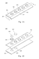
- Fig. 2B is an explosion diagram of a capacitance sensing switch module according to an embodiment of the present invention.
- Fig. 2C is a cross section view from an AA' line in the Fig. 2A . It is noticed that only one capacitance sensing switch key is illustrated in Fig. 2C . However, in another embodiment, the capacitance sensing switch module can have a lot of capacitance sensing switch keys. Please refer to Fig. 2A, 2B and 2C .
- the capacitance sensing switch module 200 includes a plate 201, a plurality of key 202, a plurality of insulating pad 203, a circuit board 204 and a plurality of foil 205.
- the material of the plate 201 is a metal.
- the material of the plate 201 can be a non-metal. Holes passing through the plate 201 are formed.
- the keys 202 and the insulating pads 203 are disposed in the holes respectively.
- the insulating pads 203 are disposed between the keys 202 and the plate 201, the key 202 and the plate 201 are separated by the insulating pad 203.
- the circuit board 204 is disposed under the plate 201.
- the foils 205 are disposed on the circuit board 204 and on the positions corresponding to the keys 202. There is an insulation gap 206 between the foil 205 and corresponding key 202.
- the keys 202 are connected to a control circuit formed in the circuit board 204 through the foils 205.
- a user can touch the capacitance sensing switch keys 202 to control the control circuit.
- a micro-controller (not shown in these Figs.) detects the capacitance change and generates a control signal to transfer to corresponding control circuit through the foil 205 to trigger a corresponding operation.
- the insulating pads 203 disposed between the keys 202 and the plate 201 can insulate the keys 202 from the plate 201. Therefore, when a user touches one of the capacitance sensing switch keys 202, only the charges stored in the touched capacitance sensing switch key 202 are redistributed. The charges stored in other capacitance sensing switch keys 202 are kept. Therefore, only the corresponding operation controlled by the touched capacitance sensing switch key 202 is triggered.
- the insulating pads 203 is a plastic pad or an elastic pad made by a rubber.
- the insulating pads 203 is totally or partially filled between the keys 202 and the plate 201.
- the insulating pads 203 is made by an elastic material.
- a micro-controller can detect a larger capacitance change value. That is, a larger change value of capacitance can be set as a threshold value to trigger the capacitance sensing switch. Such larger threshold value can prevent the control circuit be unwanted triggered by environmental factors.
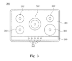
- Fig. 3 is a schematic diagram of a cooktop according to an embodiment of the present invention.
- the cooktop 300 includes a glass plate 301, a plurality of burners 302 embedded in the glass plate 301, and a capacitance sensing switch module 200 disposed in a side of the glass plate 301.
- the capacitance sensing switch module 200 includes keys 202 to control the burners 302 respectively.
- a user can touch the keys 202 to switch the operation of the burners. For example, a user uses his finger to touch the key 202, charges on this key 202 is redistributed through the user body to change the capacitance.
- a micro-controller detects the capacitance change and generates a signal to control the corresponding burner 302.
- the capacitance sensing switch module 200 of the present invention is an independent module and separated from the glass plate 301. Therefore, the appearance of the capacitance sensing switch module 200 can be varied based on the usage environment. Moreover, because the capacitance sensing switch module 200 is separated from the glass plate 301, even though the glass plate 301 has a higher temperature, the capacitance sensing switch module 200 can still maintain in a lower temperature.
- the material of the plate 301 of the capacitance sensing switch module 200 is not limited to a glass. Therefore, different color can be coated in the capacitance sensing switch module 200 to get a better visual feeling.
- keys 202 are embedded in the plate 301. Therefore, the capacitance sensing switch module 200 has a flat surface.
- the capacitance sensing switch module 200 is located in the front side of the glass plate 301.
- the capacitance sensing switch module 200 can be located in the right side or left side of the glass plate 301 or other designed position.
Landscapes
- Engineering & Computer Science (AREA)
- Chemical & Material Sciences (AREA)
- Combustion & Propulsion (AREA)
- Mechanical Engineering (AREA)
- General Engineering & Computer Science (AREA)
- Switches That Are Operated By Magnetic Or Electric Fields (AREA)
- Push-Button Switches (AREA)
- Electronic Switches (AREA)
Applications Claiming Priority (1)
| Application Number | Priority Date | Filing Date | Title |
|---|---|---|---|
| CN201110072136.XA CN102684665B (zh) | 2011-03-15 | 2011-03-15 | 电容式开关模块 |
Publications (2)
| Publication Number | Publication Date |
|---|---|
| EP2501043A2 true EP2501043A2 (de) | 2012-09-19 |
| EP2501043A3 EP2501043A3 (de) | 2017-05-31 |
Family
ID=44735796
Family Applications (1)
| Application Number | Title | Priority Date | Filing Date |
|---|---|---|---|
| EP11172981.0A Withdrawn EP2501043A3 (de) | 2011-03-15 | 2011-07-07 | Kapazitätempfindliches Schaltermodul |
Country Status (4)
| Country | Link |
|---|---|
| US (1) | US8729432B2 (de) |
| EP (1) | EP2501043A3 (de) |
| JP (1) | JP5332067B2 (de) |
| CN (1) | CN102684665B (de) |
Families Citing this family (8)
| Publication number | Priority date | Publication date | Assignee | Title |
|---|---|---|---|---|
| CN104038199A (zh) * | 2013-03-08 | 2014-09-10 | 台达电子工业股份有限公司 | 具有压电元件的开关控制模块及其所适用的电器装置 |
| US20150014784A1 (en) * | 2013-07-12 | 2015-01-15 | Delta Electronics, Inc. | Cascode switch device |
| US20150212543A1 (en) * | 2014-01-29 | 2015-07-30 | Htc Corporation | Electronic device |
| CN104808874B (zh) * | 2014-01-29 | 2018-03-06 | 宏达国际电子股份有限公司 | 电子装置 |
| FR3018171B1 (fr) * | 2014-03-10 | 2017-01-27 | Eurokera | Plan de travail en vitroceramique |
| CN109907850B (zh) * | 2017-12-13 | 2021-08-27 | 东莞市沃伦电子科技有限公司 | 可水洗触摸控制的护理装置 |
| US10935253B2 (en) | 2018-06-13 | 2021-03-02 | Electrolux Home Products, Inc. | Switch box for a cooktop appliance |
| CN110701644A (zh) * | 2019-10-16 | 2020-01-17 | 北京智米科技有限公司 | 操控显示面板及其制造方法以及电磁炉 |
Family Cites Families (16)
| Publication number | Priority date | Publication date | Assignee | Title |
|---|---|---|---|---|
| JPS62103932A (ja) * | 1985-10-29 | 1987-05-14 | シチズン時計株式会社 | タツチスイツチ構造 |
| JP2615560B2 (ja) | 1986-07-23 | 1997-05-28 | 日産自動車株式会社 | 表面硬化処理装置の異常検出方法 |
| JPS6333519U (de) * | 1986-08-21 | 1988-03-04 | ||
| JPH0612930B2 (ja) | 1986-10-16 | 1994-02-16 | 富士電機株式会社 | 無効電力補償用制御装置 |
| JPS6399727U (de) * | 1986-12-18 | 1988-06-28 | ||
| JP2005055043A (ja) * | 2003-08-01 | 2005-03-03 | Rinnai Corp | 加熱調理器 |
| JP2005308341A (ja) * | 2004-04-23 | 2005-11-04 | Rinnai Corp | コンロ |
| JP2006194481A (ja) * | 2005-01-12 | 2006-07-27 | Matsushita Electric Ind Co Ltd | ガスコンロ |
| CN100359450C (zh) * | 2005-04-08 | 2008-01-02 | 义隆电子股份有限公司 | 能够引发按键感觉的触控板 |
| JP2006322674A (ja) * | 2005-05-19 | 2006-11-30 | Rinnai Corp | コンロ |
| JP2006336101A (ja) * | 2005-06-06 | 2006-12-14 | Polymatech Co Ltd | 金属調加飾樹脂成形体およびキーシート並びに金属調加飾樹脂成形体の製造方法 |
| JP2007119250A (ja) * | 2005-10-26 | 2007-05-17 | Inventio Ag | エレベータ用の制御パネル、およびこの制御パネルを備えたエレベータ |
| CN200941352Y (zh) * | 2006-08-21 | 2007-08-29 | 松永国际科技股份有限公司 | 面板式按键开关 |
| DE102007035455A1 (de) * | 2007-07-26 | 2009-02-05 | Diehl Ako Stiftung & Co. Kg | Kapazitiver Berührungsschalter |
| JP4533446B2 (ja) * | 2008-06-04 | 2010-09-01 | 日本写真印刷株式会社 | 加飾シート、操作パネルの製造方法、操作パネルおよび電子機器 |
| JP5197490B2 (ja) * | 2009-05-29 | 2013-05-15 | 信越ポリマー株式会社 | 静電容量型入力デバイス |
-
2011
- 2011-03-15 CN CN201110072136.XA patent/CN102684665B/zh not_active Expired - Fee Related
- 2011-05-31 JP JP2011122248A patent/JP5332067B2/ja not_active Expired - Fee Related
- 2011-07-07 EP EP11172981.0A patent/EP2501043A3/de not_active Withdrawn
- 2011-08-24 US US13/216,254 patent/US8729432B2/en not_active Expired - Fee Related
Non-Patent Citations (1)
| Title |
|---|
| None |
Also Published As
| Publication number | Publication date |
|---|---|
| US20120234822A1 (en) | 2012-09-20 |
| CN102684665B (zh) | 2016-03-02 |
| US8729432B2 (en) | 2014-05-20 |
| JP5332067B2 (ja) | 2013-11-06 |
| JP2012195272A (ja) | 2012-10-11 |
| EP2501043A3 (de) | 2017-05-31 |
| CN102684665A (zh) | 2012-09-19 |
Similar Documents
| Publication | Publication Date | Title |
|---|---|---|
| US8729432B2 (en) | Capacitance sensing switch module | |
| US8168908B2 (en) | Capacitive touch switch | |
| KR200451671Y1 (ko) | 터치 센서 | |
| US9948297B2 (en) | Pressure dependent capacitive sensing circuit switch construction | |
| US7851720B2 (en) | Capacitive touch switch, circuit configuration for a capacitive touch switch and control device for an electronic domestic appliance with at least one capacitive touch switch | |
| EP2048780B1 (de) | Kapazitiver Berührungsschalter und Haushaltsgerät damit | |
| SI1704642T1 (sl) | Posluževalna priprava s kapacitivnim senzorskim elementom in električna priprava s takšno posluževalno pripravo | |
| US9973190B2 (en) | Capacitive proximity and/or contact switch | |
| US9571096B2 (en) | Touch panel based switch | |
| WO2012175336A3 (de) | Kapazitive bedien- und anzeigeeinrichtung für ein haushaltsgerät und haushaltsgerät mit einer solchen bedien- und anzeigeeinrichtung | |
| WO2021005274A8 (fr) | Dispositif de commande 3d pour interface tactile capacitive | |
| CN201555273U (zh) | 一种电磁炉的触摸控制装置 | |
| US20140160641A1 (en) | Electronic apparatus | |
| CN202026294U (zh) | 一种台灯触摸开关的结构 | |
| KR101385504B1 (ko) | 자석을 이용한 조그 스위치 | |
| CN113687740B (zh) | 电容式触摸感应板及具有其的电器 | |
| US9306562B2 (en) | Household appliance comprising touch sensors | |
| JP6333534B2 (ja) | 属性識別システム | |
| EP2874317A1 (de) | Kapazitive Steuerschnittstelle mit verbesserter Verwendungssicherheit | |
| JP7773339B2 (ja) | タッチキー、電子機器、および空気清浄機 | |
| CN104253602A (zh) | 电容式触摸感应按键及电子装置 | |
| CN205425052U (zh) | 按键触摸式电磁炉 | |
| US9054710B2 (en) | Touch keyboard with improved structure | |
| CN212305295U (zh) | 触摸按键结构及具有其的电器 | |
| TWI678653B (zh) | 具有觸控功能的電子裝置及其觸控模組 |
Legal Events
| Date | Code | Title | Description |
|---|---|---|---|
| PUAI | Public reference made under article 153(3) epc to a published international application that has entered the european phase |
Free format text: ORIGINAL CODE: 0009012 |
|
| 17P | Request for examination filed |
Effective date: 20110707 |
|
| AK | Designated contracting states |
Kind code of ref document: A2 Designated state(s): AL AT BE BG CH CY CZ DE DK EE ES FI FR GB GR HR HU IE IS IT LI LT LU LV MC MK MT NL NO PL PT RO RS SE SI SK SM TR |
|
| AX | Request for extension of the european patent |
Extension state: BA ME |
|
| PUAL | Search report despatched |
Free format text: ORIGINAL CODE: 0009013 |
|
| AK | Designated contracting states |
Kind code of ref document: A3 Designated state(s): AL AT BE BG CH CY CZ DE DK EE ES FI FR GB GR HR HU IE IS IT LI LT LU LV MC MK MT NL NO PL PT RO RS SE SI SK SM TR |
|
| AX | Request for extension of the european patent |
Extension state: BA ME |
|
| RIC1 | Information provided on ipc code assigned before grant |
Ipc: H03K 17/965 20060101ALI20170421BHEP Ipc: F24C 7/08 20060101ALI20170421BHEP Ipc: H03K 17/96 20060101AFI20170421BHEP |
|
| RBV | Designated contracting states (corrected) |
Designated state(s): AL AT BE BG CH CY CZ DE DK EE ES FI FR GB GR HR HU IE IS IT LI LT LU LV MC MK MT NL NO PL PT RO RS SE SI SK SM TR |
|
| STAA | Information on the status of an ep patent application or granted ep patent |
Free format text: STATUS: EXAMINATION IS IN PROGRESS |
|
| 17Q | First examination report despatched |
Effective date: 20180816 |
|
| GRAP | Despatch of communication of intention to grant a patent |
Free format text: ORIGINAL CODE: EPIDOSNIGR1 |
|
| STAA | Information on the status of an ep patent application or granted ep patent |
Free format text: STATUS: GRANT OF PATENT IS INTENDED |
|
| INTG | Intention to grant announced |
Effective date: 20190403 |
|
| RAP1 | Party data changed (applicant data changed or rights of an application transferred) |
Owner name: DELTA ELECTRONICS, INC. |
|
| STAA | Information on the status of an ep patent application or granted ep patent |
Free format text: STATUS: THE APPLICATION IS DEEMED TO BE WITHDRAWN |
|
| 18D | Application deemed to be withdrawn |
Effective date: 20190814 |