EP2501167A1 - Station de base radioélectrique et procédé de commande de communication - Google Patents
Station de base radioélectrique et procédé de commande de communication Download PDFInfo
- Publication number
- EP2501167A1 EP2501167A1 EP10828399A EP10828399A EP2501167A1 EP 2501167 A1 EP2501167 A1 EP 2501167A1 EP 10828399 A EP10828399 A EP 10828399A EP 10828399 A EP10828399 A EP 10828399A EP 2501167 A1 EP2501167 A1 EP 2501167A1
- Authority
- EP
- European Patent Office
- Prior art keywords
- base station
- radio
- radio base
- interference
- interference information
- Prior art date
- Legal status (The legal status is an assumption and is not a legal conclusion. Google has not performed a legal analysis and makes no representation as to the accuracy of the status listed.)
- Withdrawn
Links
- 238000004891 communication Methods 0.000 title claims abstract description 105
- 238000000034 method Methods 0.000 title claims description 11
- 238000012545 processing Methods 0.000 claims description 6
- 230000005540 biological transmission Effects 0.000 description 43
- 238000010586 diagram Methods 0.000 description 6
- 230000000694 effects Effects 0.000 description 2
- 230000006870 function Effects 0.000 description 2
- 238000010295 mobile communication Methods 0.000 description 2
- 238000012937 correction Methods 0.000 description 1
- 238000013461 design Methods 0.000 description 1
- 239000000284 extract Substances 0.000 description 1
- 230000007774 longterm Effects 0.000 description 1
- 230000004044 response Effects 0.000 description 1
Images


Classifications
-
- H—ELECTRICITY
- H04—ELECTRIC COMMUNICATION TECHNIQUE
- H04W—WIRELESS COMMUNICATION NETWORKS
- H04W88/00—Devices specially adapted for wireless communication networks, e.g. terminals, base stations or access point devices
- H04W88/08—Access point devices
-
- H—ELECTRICITY
- H04—ELECTRIC COMMUNICATION TECHNIQUE
- H04L—TRANSMISSION OF DIGITAL INFORMATION, e.g. TELEGRAPHIC COMMUNICATION
- H04L5/00—Arrangements affording multiple use of the transmission path
- H04L5/003—Arrangements for allocating sub-channels of the transmission path
- H04L5/0058—Allocation criteria
- H04L5/0062—Avoidance of ingress interference, e.g. ham radio channels
-
- H—ELECTRICITY
- H04—ELECTRIC COMMUNICATION TECHNIQUE
- H04B—TRANSMISSION
- H04B17/00—Monitoring; Testing
- H04B17/20—Monitoring; Testing of receivers
- H04B17/24—Monitoring; Testing of receivers with feedback of measurements to the transmitter
-
- H—ELECTRICITY
- H04—ELECTRIC COMMUNICATION TECHNIQUE
- H04B—TRANSMISSION
- H04B17/00—Monitoring; Testing
- H04B17/30—Monitoring; Testing of propagation channels
- H04B17/309—Measuring or estimating channel quality parameters
- H04B17/345—Interference values
-
- H—ELECTRICITY
- H04—ELECTRIC COMMUNICATION TECHNIQUE
- H04L—TRANSMISSION OF DIGITAL INFORMATION, e.g. TELEGRAPHIC COMMUNICATION
- H04L5/00—Arrangements affording multiple use of the transmission path
- H04L5/003—Arrangements for allocating sub-channels of the transmission path
- H04L5/0032—Distributed allocation, i.e. involving a plurality of allocating devices, each making partial allocation
- H04L5/0035—Resource allocation in a cooperative multipoint environment
-
- H—ELECTRICITY
- H04—ELECTRIC COMMUNICATION TECHNIQUE
- H04L—TRANSMISSION OF DIGITAL INFORMATION, e.g. TELEGRAPHIC COMMUNICATION
- H04L5/00—Arrangements affording multiple use of the transmission path
- H04L5/003—Arrangements for allocating sub-channels of the transmission path
- H04L5/0058—Allocation criteria
- H04L5/0073—Allocation arrangements that take into account other cell interferences
-
- H—ELECTRICITY
- H04—ELECTRIC COMMUNICATION TECHNIQUE
- H04W—WIRELESS COMMUNICATION NETWORKS
- H04W24/00—Supervisory, monitoring or testing arrangements
-
- H—ELECTRICITY
- H04—ELECTRIC COMMUNICATION TECHNIQUE
- H04W—WIRELESS COMMUNICATION NETWORKS
- H04W72/00—Local resource management
- H04W72/50—Allocation or scheduling criteria for wireless resources
- H04W72/54—Allocation or scheduling criteria for wireless resources based on quality criteria
- H04W72/541—Allocation or scheduling criteria for wireless resources based on quality criteria using the level of interference
-
- H—ELECTRICITY
- H04—ELECTRIC COMMUNICATION TECHNIQUE
- H04W—WIRELESS COMMUNICATION NETWORKS
- H04W72/00—Local resource management
- H04W72/20—Control channels or signalling for resource management
- H04W72/27—Control channels or signalling for resource management between access points
Definitions
- the present invention relates to a radio base station configured to perform processing for causing a different radio base station to control interference received from a radio terminal connected to the different radio base station, and to a communication control method for the radio base station.
- LTE Long Term Evolution
- one radio base station is assumed to control interference received from a radio terminal connected to a neighboring radio base station (interference in the uplink direction from a neighboring cell) by exchanging information on an interference condition called OI (Overload Indicator) between the radio base stations.
- OI Overload Indicator
- the one radio base station measures interference power in the uplink direction from the neighboring cell for each radio resource unit called a resource block (RB) and transmits ternary information indicating any of "small interference”, “large interference”, and "very large interference”, for instance, to the neighboring radio base station depending on the interference power.
- the neighboring radio base station that receives the ternary information can control transmission power (transmission power in the uplink direction) of the connected radio terminal by use of the ternary information.
- the neighboring radio base station controls the radio terminal upon receipt of the information indicating that the interference power is "very large” in such a manner as to lower the transmission power in the uplink direction, thereby reducing the interference power in the uplink direction on the one radio base station.
- an objective of the present invention is to provide a radio base station and a communication control method, which are capable of preventing reduction in channel capacity of a radio communication system as a whole.
- a radio base station configured to perform processing to cause a different radio base station (second radio base station 1B) to control interference received from a radio terminal (radio terminal 2B) connected to the different radio base station, comprises: an interference power measuring unit (interference power measuring unit 150) configured to measure interference power received from the radio terminal; a communication load measuring unit (communication loadmeasuring unit 152) configured to measure a radio communication load in the radio base station; an interference information generator (interference information generator 154) configured to generate interference information based on the radio communication load measured by the communication load measuring unit, the interference information being information related to the interference power measured by the interference power measuring unit; and a transmitter (transmission processor 156) configured to transmit the interference information generated by the interference information generator to the different radio base station.
- an interference power measuring unit interference power measuring unit 150
- a communication load measuring unit communication loadmeasuring unit 152
- an interference information generator interference information generator 154 configured to generate interference information based on the radio communication load measured by the communication load measuring unit, the interference information being information related to the interference power measured by
- the above-described radio base station not only measures the interference power received from the radio terminal connected to the different radio base station but also measures the radio communication load in the radio base station, then generates the interference information being the information related to the interference power based on the radio communication load, and transmits the information to the different radio base station.
- the different radio base station can control the transmission power of the radio terminal in consideration of the radio communication load in the radio base station which is the sender of the interference information.
- the interference information generator generates the interference information indicating smaller interference power as the radio communication load is smaller.
- the interference information generator generates the interference information based on a value obtained by multiplying a value indicating the radio communication load by a value indicating the interference power.
- the interference information generator generates the interference information indicating large interference when a value indicating the radio communication load is equal to or above a first threshold and a value indicating the interference power is equal to or above a second threshold.
- a fifth feature of the present invention is summarized as follows.
- the interference power measuring unit measures interference power of a radio resource in a predetermined frequency band, and the interference information generator generates interference information corresponding to the radio resource in the predetermined frequency band.
- the interference power measuring unit measures interference power for each minimum allocation unit in terms of the radio resource allocated to the radio terminal
- the interference information generator generates interference information for each minimum allocation unit in terms of the radio resource allocated to the radio terminal.
- a seventh feature of the present invention is summarized as follows.
- a communication control method for a radio base station configured to perform processing to cause a different radio base station to control interference received from a radio terminal connected to the different radio base station, comprises: a step of measuring, at the radio base station, interference power received from the radio terminal; a step of measuring, at the radio base station, a radio communication load in the radio base station; a step of generating, at the radio base station, interference information based on the measured radio communication load, the interference information being information related to the measured interference power; and a step of transmitting the generated interference information from the radio base station to the different radio base station.
- a communication control method for a radio base station configured to perform communication in an uplink while allocating a radio resource block to a radio terminal in a cell of the radio base station, comprises: an interference information transmitting step of transmitting interference information from the radio base station to a different radio base station, the interference information indicating an interfered radio resource block in the uplink, wherein the interference information is generated based on a radio communication load in the radio base station.
- Fig. 1 is an overall schematic configuration diagram of a radio communication system 10 according to an embodiment of the present invention.
- the radio communication system 10 includes a configuration based on LTE Release9 which is a 3.9-generation (3.9G) mobile communications system or on LTE-Advanced which is positioned as a 4th generation (4G) mobile communications system, for example.
- LTE Release9 which is a 3.9-generation (3.9G) mobile communications system
- LTE-Advanced which is positioned as a 4th generation (4G) mobile communications system, for example.
- the radio communication system 10 includes a first radio base station 1A which defines a cell 3A and a second radio base station 1B which defines a cell 3B.
- the cell 3B is a neighbor cell to the cell 3A.
- Each of the cell 3A and the cell 3B has a radius of several hundred [m], for example.
- a radio terminal 2A located in the cell 3A is connected to the first radio base station 1A while a radio terminal 2B located in the cell 3B is connected to the second ration base station 1B.
- the first radio base station 1A and the second radio base station 1B are installed in positions based on station layout design formed by a common carrier in consideration of intercell interference.
- the first radio base station 1A is connected to the second radio base station 1B by using an unillustrated dedicated line or the like to establish X2 connection which is a logical transmission path on a transport layer.
- the first radio base station 1A allocates one or more resource blocks (RB) each in an uplink direction and in a downlink direction, which represent radio resources in minimum allocation units, to the radio terminal 2A and performs radio communications with the radio terminal 2A.
- the second radio base station 1B allocates one or more resource blocks each in the uplink direction and in the downlink direction to the radio terminal 2B and performs radio communications with the radio terminal 2B.
- a frequency band of the resource block corresponding to an uplink (which is a link directed from the radio terminal 2A to the first radio base station 1A and will be hereinafter referred to as a "first uplink") used for radio communications when the first radio base station 1A and the radio terminal 2A are connected to each other and performing the radio communications is the same as a frequency band of the resource block corresponding to an uplink (which is a link directed from the radio terminal 2B to the second radio base station 1B and will be hereinafter referred to as a "second uplink”) used for radio communications when the second radio base station 1B and the radio terminal 2B are connected to each other and performing the radio communications, the first radio base station 1A performing the radio communications with the radio terminal 2A will be interfered with a radio signal transmitted from the radio terminal 2B to the second radio base station 1B by use of the second uplink.
- first uplink which is a link directed from the radio terminal 2A to the first radio base station 1A and will be hereinafter referred to as a "second up
- the first radio base station 1A requests the second radio base station 1B to control transmission power of the radio terminal 2B when the first radio base station 1A receives the interference from the radio terminal 2B.
- the second radio base station 1B reduces the interference by controlling the transmission power of the radio terminal 2B in response to the request.
- Fig. 2 is a block diagram showing a configuration of the first radio base station 1A.
- the first radio base station 1A includes a controller 102, a storage unit 103, a wired communication unit 104, a radio communication unit 105, and an antenna unit 107.
- the controller 102 is formed of a CPU, for example, and controls various functions included in the first radio base station 1A.
- the storage unit 103 is formed of a memory, for example, and stores a variety of information used for the control by the first radio base station 1A and the like.
- the wired communication unit 104 performs transmission and reception of data to and from the second radio base station 1B.
- the radio communication unit 105 is formed by use of a radio frequency (RF) circuit or a baseband (BB) circuit, for example, and performs transmission and reception of radio signals to and from the radio terminal 2A through the antenna unit 107. Moreover, the radio communication unit 105 performs coding and modulation of transmitted signals as well as demodulation and decoding of received signals. Furthermore, the radio communication unit 105 outputs reception data acquired by demodulation and decoding of the received signals, to the controller 102.
- RF radio frequency
- BB baseband
- the radio communication unit 105 includes an interference power measuring unit 150.
- the controller 102 includes a communication load measuring unit 152, an interference information generator 154, and a transmission processor 156.
- the interference power measuring unit 150 in the radio communication unit 105 measures power of the interference received by way of a radio signal transmitted from the radio terminal 2B to the second radio base station 1B using the second uplink while a radio signal transmitted from the radio terminal 2A using the first uplink is received. Specifically, the interference power measuring unit 150 measures the power in terms of a component of the radio signal transmitted from the radio terminal 2B to the second radio base station 1B using the second uplink out of the received radio signals for each of one or more resource blocks allocated to the radio terminal 2A.
- the communication load measuring unit 152 in the controller 102 calculates a ratio (a traffic amount ratio) of an actual traffic amount relative to a maximum processable traffic amount of the first radio base station 1A as a radio communication load in the first radio base station 1A. Specifically, the communication load measuring unit 152 measures an amount of transmission data outputted from the controller 102 to the radio communication unit 105. Moreover, the communication load measuring unit 152 calculates the traffic amount ratio by dividing the amount of transmission data thus measured by a predetermined maximum processable traffic amount in the downlink direction. Alternatively, the communication load measuring unit 152 measures an amount of reception data outputted from the radio communication unit 105 to the controller 102. Moreover, the communication load measuring unit 152 calculates the traffic amount ratio by dividing the amount of reception data thus measured by a predetermined maximum processable traffic amount in the uplink direction.
- the maximum processable traffic amount in the downlink direction and the maximum processable traffic amount in the uplink direction are stored in the storage unit 103.
- the communication load measuring unit 152 may perform correction in such a manner as to increase the calculated traffic amount ratio along with an increase in the required throughput and the required amount of data in the radio communications between the first radio base station 1A and the radio terminal 2A.
- the interference information generator 154 in the controller 102 multiplies each of interference power values for the respective resource blocks measured by the interference power measuring unit 150 by the traffic amount ratio measured by the communication load measuring unit 152.
- the interference information generator 154 generates binary interference information indicating either "0" or "1” as an OI (Overload Indicator). Specifically, in terms of each of the multiplied values of the respective resource blocks, the interference information generator 154 generates "1" indicating that the interference is large as the interference information when the multiplied value is equal to or above a first threshold or generates "0" indicating that the interference is small as the interference information when the multiplied value is below the first threshold.
- the first threshold is stored in the storage unit 103 in advance.
- the transmission processor 156 in the controller 102 extracts identification information on the radio terminal 2B being the sender of the radio signal as well as identification information on the second radio base station 1B being the destination included in reception data corresponding to the radio signal transmitted from the radio terminal 2B to the second radio base station 1B using the second uplink.
- the transmission processor 156 provides the interference information on each of the resource blocks generated by the interference information generator 154 with identification information on the resource block corresponding to the interference information and with the extracted identification information on the radio terminal 2B.
- the transmission processor 156 sets the destination of the interference information on each of the resource blocks to the extracted identification information on the second radio base station 1B, and transmits the interference information provided with the identification information on the resource block and the identification information on the radio terminal 2B to the second radio base station 1B through the wired communication unit 104.
- Fig. 3 is a block diagram showing a configuration of the second radio base station 1B.
- the second radio base station 1B includes a controller 112, a storage unit 113, a wired communication unit 114, a radio communication unit 115, and an antenna unit 117.
- the controller 112 is formed of a CPU, for example, and controls various functions included in the second radio base station 1B.
- the storage unit 113 is formed of a memory, for example, and stores a variety of information used for the control by the second radio base station 1B and the like.
- the wired communication unit 114 performs transmission and reception of the data to and from the first radio base station 1A.
- the radio communication unit 115 is formed by use of a radio frequency (RF) circuit or a baseband (BB) circuit, for example, and performs transmission and reception of radio signals to and from the radio terminal 2B through the antenna unit 117. Moreover, the radio communication unit 115 performs coding and modulation of transmitted signals as well as demodulation and decoding of received signals. Furthermore, the radio communication unit 115 outputs reception data acquired by demodulation and decoding of the received signals, to the controller 112.
- RF radio frequency
- BB baseband
- the controller 112 includes a reception processor 160 and a radio terminal transmission power controller 162.
- the reception processor 160 in the controller 112 receives the interference information on each of the resource blocks from the first radio base station 1A through the wired communication unit 114.
- the radio terminal transmission power controller 162 in the controller 112 controls the transmission power of the radio terminal 2B based on the interference information on each of the resource blocks received by the reception processor 160. Specifically, the radio terminal transmission power controller 162 determines the radio terminal 2B subject to control of the transmission power based on the identification information on the radio terminal 2B attached to each piece of the interference information on each of the resource blocks received by the reception processor 160. Next, the radio terminal transmission power controller 162 generates a transmission power reduction request including the identification information on the resource block attached to the interference information when the interference information is "1".
- the radio terminal transmission power controller 162 transmits the generated transmission power reduction request to the radio terminal 2B through the radio communication unit 115 and the antenna unit 117. Upon receipt of this transmission power reduction request, the radio terminal 2B reduces the transmission power for the resource block corresponding to the identification information on the resource block which is attached to the transmission power reduction request.
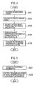
- Fig. 4 is a flowchart showing operations of the first radio base station 1A.
- the interference power measuring unit 150 in the radio communication unit 105 measures the power of the interference received by way of the radio signal transmitted from the radio terminal 2B to the second radio base station 1B using the second uplink while the radio signal transmitted from the radio terminal 2A using the first uplink is received for each of the resource blocks allocated to the radio terminal 2A.
- step S102 the communication load measuring unit 152 in the controller 102 calculates the ratio (the traffic amount ratio) of the actual traffic amount relative to the maximum processable traffic amount of the first radio base station 1A.
- step S103 the interference information generator 154 in the controller 102 multiplies the each of the interference power values for the respective resource blocks by the traffic amount ratio measured by the communication load measuring unit 152.
- step S104 the interference information generator 154 in the controller 102 generates the interference information on each of the resource blocks corresponding to the multiplied value for each of the resource blocks.
- step S105 the transmission processor 156 in the controller 102 transmits the interference information on each of the resource blocks to the second radio base station 1B.
- Fig. 5 is a flowchart showing operations of the second radio base station 1B.
- the reception processor 160 in the controller 112 receives the interference information on each of the resource blocks from the first radio base station 1A.
- step S202 the radio terminal transmission power controller 162 in the controller 112 controls the transmission power of the radio terminal 2B based on the received interference information on each of the resource blocks.
- the first radio base station 1A measures the power of the interference received by way of the radio signal transmitted from the radio terminal 2B to the second radio base station 1B using the second uplink for each of one or more resource blocks allocated to the radio terminal 2A, and calculates the traffic amount ratio of the first radio base station 1A. Moreover, the first radio base station 1A multiplies the interference power value for each of the resource blocks by the traffic amount ratio measured by the communication load measuring unit 152, generates the interference information on each of the resource blocks corresponding to the multiplied value for each of the resource blocks, and transmits the interference information to the second radio base station 1B.
- the second radio base station 1B receives the interference information on each of the resource blocks from the first radio base station 1A, and controls the transmission power of the radio terminal 2B based on the interference information on each of the resource blocks.
- the transmission power of the radio terminal 2B is controlled under the condition where not only the power of the interference but also the radio communication load in the first radio base station 1A are taken into account. Hence it is possible to prevent reduction in channel capacity of the radio communication system 10 as a whole due to excessive reduction in the transmission power of the radio terminal 2B.
- the first radio base station 1A generates the interference information by comparing the multiplied value of the traffic amount ratio and the interference power value in terms of the first radio base station 1A with the threshold.
- the method of generating the interference information in consideration of the radio communication load is not limited only to the foregoing.
- the interference information generator 154 in the controller 102 may generate "1" indicating that the interference is large as the interference information when the interference power value is equal to or above a third threshold and the traffic amount ratio is equal to or above a fourth threshold, or may generate "0" indicating that the interference is small as the interference information at least when the interference power value is below the third threshold or when the traffic amount ratio is below the fourth threshold.
- the third and fourth thresholds are stored in the storage unit 103.
- the interference information does not have to be composed of binary values.
- the interference information generator 154 in the controller 102 of the first radio base station 1A may generate the multiplied value of the interference power value and the traffic amount ratio as the interference information.
- Such interference information indicates that the interference is smaller as the traffic amount ratio is smaller, i.e., as the radio communication load in the first radio base station 1A is smaller.
- the radio terminal transmission power controller 162 in the controller 112 of the second radio base station 1B generates the transmission power reduction request in such a manner as to set a larger transmission power reduction ratio as the value of the interference information is greater, and transmits the request to the radio terminal 2B.
- the first radio base station 1A measures the interference power and further generates and transmits the interference information for each of the resource blocks. Instead, it is also possible to calculate an average value of the interference power of all the resource blocks allocated to the radio terminal 2A and to generate and transmit a single piece of the interference information corresponding to the average value of the interference power.
- the second radio base station 1B controls the transmission power of the radio terminal 2B based on the single piece of the interference information, or in other words, on the interference information corresponding to all the resource blocks allocated to the radio terminal 2A.
- the radio communication load is not limited to the traffic amount ratio at the first radio base station 1A.
- the radio communication load may also be a usage rate of the resource blocks at the first radio base station 1A, the bare traffic amount itself at the first radio base station 1A, a processing load associated with the radio communication by the first radio base station 1A, and so forth.
- the radio communication system 10 has the configuration based on LTE Release9 or LTE-Advanced.
- the system may have a configuration based on any other communication standards.
- the radio base station and the communication control method of the present invention can prevent reduction in channel capacity of a radio communication system as a whole, and are therefore useful as a radio base station and a communication control method.
Landscapes
- Engineering & Computer Science (AREA)
- Signal Processing (AREA)
- Computer Networks & Wireless Communication (AREA)
- Quality & Reliability (AREA)
- Physics & Mathematics (AREA)
- Electromagnetism (AREA)
- Mobile Radio Communication Systems (AREA)
Applications Claiming Priority (2)
| Application Number | Priority Date | Filing Date | Title |
|---|---|---|---|
| JP2009256482 | 2009-11-09 | ||
| PCT/JP2010/069916 WO2011055841A1 (fr) | 2009-11-09 | 2010-11-09 | Station de base radioélectrique et procédé de commande de communication |
Publications (1)
| Publication Number | Publication Date |
|---|---|
| EP2501167A1 true EP2501167A1 (fr) | 2012-09-19 |
Family
ID=43970073
Family Applications (1)
| Application Number | Title | Priority Date | Filing Date |
|---|---|---|---|
| EP10828399A Withdrawn EP2501167A1 (fr) | 2009-11-09 | 2010-11-09 | Station de base radioélectrique et procédé de commande de communication |
Country Status (6)
| Country | Link |
|---|---|
| US (1) | US9026166B2 (fr) |
| EP (1) | EP2501167A1 (fr) |
| JP (1) | JP5259833B2 (fr) |
| KR (1) | KR20120066071A (fr) |
| CN (1) | CN102598750A (fr) |
| WO (1) | WO2011055841A1 (fr) |
Cited By (1)
| Publication number | Priority date | Publication date | Assignee | Title |
|---|---|---|---|---|
| EP2538731A4 (fr) * | 2010-02-15 | 2016-06-08 | Kyocera Corp | Station de base radio et procédé de commande de communication |
Families Citing this family (4)
| Publication number | Priority date | Publication date | Assignee | Title |
|---|---|---|---|---|
| CN105580474B (zh) * | 2013-09-27 | 2019-03-26 | 日本电气株式会社 | 通信设备、通信系统和控制方法 |
| KR102277257B1 (ko) * | 2014-05-19 | 2021-07-14 | 엘지전자 주식회사 | 전이중 통신 방식 및 반이중 통신방식을 지원하는 시스템에서 통신을 수행하는 방법 및 이를 위한 장치 |
| TWI572221B (zh) * | 2014-12-01 | 2017-02-21 | 財團法人資訊工業策進會 | 中控伺服器及其負載平衡方法 |
| US10708907B2 (en) * | 2016-04-19 | 2020-07-07 | Qualcomm Incorporated | Interference management with adaptive resource block allocation |
Family Cites Families (9)
| Publication number | Priority date | Publication date | Assignee | Title |
|---|---|---|---|---|
| JPH0530022A (ja) | 1991-07-22 | 1993-02-05 | Nippon Telegr & Teleph Corp <Ntt> | Tdma無線通信装置 |
| US6985739B2 (en) * | 2000-12-15 | 2006-01-10 | Telefonaktiebolaget Lm Ericsson (Publ) | Admission and congestion control in a CDMA-based mobile radio communications system |
| US7236793B2 (en) * | 2001-01-31 | 2007-06-26 | Ipr Licensing, Inc. | Queuing far/far service requests in wireless network |
| EP1654821B1 (fr) | 2003-07-17 | 2011-08-24 | Interdigital Technology Corporation | Procede de signalisation pour la commande d'un reseau local sans fil (wlan) |
| DE60328235D1 (de) * | 2003-09-30 | 2009-08-13 | Mitsubishi Electric Corp | System für Mobilkommunikation zur Steuerung des Kommunikationsmodus |
| US8150412B2 (en) * | 2006-03-06 | 2012-04-03 | Alcatel Lucent | Interference mitigation in a wireless communication system |
| JP4848309B2 (ja) * | 2007-05-10 | 2011-12-28 | 株式会社エヌ・ティ・ティ・ドコモ | 基地局装置及び通信制御方法 |
| KR100897953B1 (ko) | 2007-07-11 | 2009-05-18 | 후지쯔 가부시끼가이샤 | 기지국 및 그 기지국에 있어서의 간섭 저감 방법 |
| JP2009256482A (ja) | 2008-04-17 | 2009-11-05 | Bridgestone Corp | 天然ゴム及びその製造方法、並びにゴム組成物及びタイヤ |
-
2010
- 2010-11-09 EP EP10828399A patent/EP2501167A1/fr not_active Withdrawn
- 2010-11-09 US US13/508,681 patent/US9026166B2/en not_active Expired - Fee Related
- 2010-11-09 CN CN2010800495822A patent/CN102598750A/zh active Pending
- 2010-11-09 JP JP2011539424A patent/JP5259833B2/ja not_active Expired - Fee Related
- 2010-11-09 KR KR20127012079A patent/KR20120066071A/ko not_active Ceased
- 2010-11-09 WO PCT/JP2010/069916 patent/WO2011055841A1/fr not_active Ceased
Non-Patent Citations (1)
| Title |
|---|
| See references of WO2011055841A1 * |
Cited By (1)
| Publication number | Priority date | Publication date | Assignee | Title |
|---|---|---|---|---|
| EP2538731A4 (fr) * | 2010-02-15 | 2016-06-08 | Kyocera Corp | Station de base radio et procédé de commande de communication |
Also Published As
| Publication number | Publication date |
|---|---|
| JP5259833B2 (ja) | 2013-08-07 |
| KR20120066071A (ko) | 2012-06-21 |
| US20120231746A1 (en) | 2012-09-13 |
| WO2011055841A1 (fr) | 2011-05-12 |
| JPWO2011055841A1 (ja) | 2013-03-28 |
| US9026166B2 (en) | 2015-05-05 |
| CN102598750A (zh) | 2012-07-18 |
Similar Documents
| Publication | Publication Date | Title |
|---|---|---|
| US8971952B2 (en) | Radio base station and communication control method | |
| US9148789B2 (en) | Inter-system interference control | |
| JP5466034B2 (ja) | 無線基地局及び通信制御方法 | |
| KR100957314B1 (ko) | 셀룰라 무선 이동 통신 시스템에서 역방향 트래픽 로드 제어 시스템 및 방법 | |
| US8929881B2 (en) | Radio communication system, small cell base station, radio terminal, transmission power control method, and allocation control method | |
| CN101981979B (zh) | 一种下行功率分配方法、装置和系统 | |
| JP5512793B2 (ja) | 基地局 | |
| US20130281143A1 (en) | Method and apparatus for interference-aware wireless communications | |
| JP5395910B2 (ja) | 無線通信システム、基地局及び通信制御方法 | |
| US9026166B2 (en) | Radio base station and communication control method | |
| US8483154B2 (en) | Subcarrier allocation method and apparatus thereof | |
| JP2011101344A (ja) | 無線基地局及び通信制御方法 | |
| JP2012231267A (ja) | 無線基地局及び通信制御方法 | |
| WO2012137928A1 (fr) | Système de communication sans fil, station de base de faible puissance, et procédé de commande de communication |
Legal Events
| Date | Code | Title | Description |
|---|---|---|---|
| PUAI | Public reference made under article 153(3) epc to a published international application that has entered the european phase |
Free format text: ORIGINAL CODE: 0009012 |
|
| 17P | Request for examination filed |
Effective date: 20120329 |
|
| AK | Designated contracting states |
Kind code of ref document: A1 Designated state(s): AL AT BE BG CH CY CZ DE DK EE ES FI FR GB GR HR HU IE IS IT LI LT LU LV MC MK MT NL NO PL PT RO RS SE SI SK SM TR |
|
| DAX | Request for extension of the european patent (deleted) | ||
| STAA | Information on the status of an ep patent application or granted ep patent |
Free format text: STATUS: THE APPLICATION HAS BEEN WITHDRAWN |
|
| 18W | Application withdrawn |
Effective date: 20160909 |