EP2503242A2 - Tête pour chambre de combustion avec fixation pour les joints d'étanchéité des brûleurs dans des turbines à gaz - Google Patents
Tête pour chambre de combustion avec fixation pour les joints d'étanchéité des brûleurs dans des turbines à gaz Download PDFInfo
- Publication number
- EP2503242A2 EP2503242A2 EP12002047A EP12002047A EP2503242A2 EP 2503242 A2 EP2503242 A2 EP 2503242A2 EP 12002047 A EP12002047 A EP 12002047A EP 12002047 A EP12002047 A EP 12002047A EP 2503242 A2 EP2503242 A2 EP 2503242A2
- Authority
- EP
- European Patent Office
- Prior art keywords
- burner
- combustion chamber
- seal
- base plate
- recess
- Prior art date
- Legal status (The legal status is an assumption and is not a legal conclusion. Google has not performed a legal analysis and makes no representation as to the accuracy of the status listed.)
- Granted
Links
- 238000002485 combustion reaction Methods 0.000 title claims abstract description 50
- 238000011144 upstream manufacturing Methods 0.000 claims abstract description 14
- 238000007789 sealing Methods 0.000 claims description 7
- 239000002184 metal Substances 0.000 claims description 4
- 230000008719 thickening Effects 0.000 description 11
- 239000000243 solution Substances 0.000 description 8
- 238000013459 approach Methods 0.000 description 6
- 238000009434 installation Methods 0.000 description 3
- 238000004519 manufacturing process Methods 0.000 description 3
- 238000000034 method Methods 0.000 description 3
- 238000013461 design Methods 0.000 description 2
- 238000005304 joining Methods 0.000 description 2
- 241001156002 Anthonomus pomorum Species 0.000 description 1
- 230000003750 conditioning effect Effects 0.000 description 1
- 230000001419 dependent effect Effects 0.000 description 1
- 238000011161 development Methods 0.000 description 1
- 230000002349 favourable effect Effects 0.000 description 1
- 238000003780 insertion Methods 0.000 description 1
- 230000037431 insertion Effects 0.000 description 1
- 238000003754 machining Methods 0.000 description 1
- 238000012423 maintenance Methods 0.000 description 1
- 238000003825 pressing Methods 0.000 description 1
- 238000012545 processing Methods 0.000 description 1
- 125000006850 spacer group Chemical group 0.000 description 1
- 238000012360 testing method Methods 0.000 description 1
Images

Classifications
-
- F—MECHANICAL ENGINEERING; LIGHTING; HEATING; WEAPONS; BLASTING
- F23—COMBUSTION APPARATUS; COMBUSTION PROCESSES
- F23R—GENERATING COMBUSTION PRODUCTS OF HIGH PRESSURE OR HIGH VELOCITY, e.g. GAS-TURBINE COMBUSTION CHAMBERS
- F23R3/00—Continuous combustion chambers using liquid or gaseous fuel
- F23R3/28—Continuous combustion chambers using liquid or gaseous fuel characterised by the fuel supply
- F23R3/283—Attaching or cooling of fuel injecting means including supports for fuel injectors, stems, or lances
-
- F—MECHANICAL ENGINEERING; LIGHTING; HEATING; WEAPONS; BLASTING
- F23—COMBUSTION APPARATUS; COMBUSTION PROCESSES
- F23R—GENERATING COMBUSTION PRODUCTS OF HIGH PRESSURE OR HIGH VELOCITY, e.g. GAS-TURBINE COMBUSTION CHAMBERS
- F23R3/00—Continuous combustion chambers using liquid or gaseous fuel
- F23R3/002—Wall structures
-
- F—MECHANICAL ENGINEERING; LIGHTING; HEATING; WEAPONS; BLASTING
- F23—COMBUSTION APPARATUS; COMBUSTION PROCESSES
- F23R—GENERATING COMBUSTION PRODUCTS OF HIGH PRESSURE OR HIGH VELOCITY, e.g. GAS-TURBINE COMBUSTION CHAMBERS
- F23R2900/00—Special features of, or arrangements for continuous combustion chambers; Combustion processes therefor
- F23R2900/00012—Details of sealing devices
Definitions
- the invention relates to a combustion chamber head of a gas turbine, in detail, the invention relates to a combustion chamber head according to the features of the preamble of claim 1.
- a gasket around a burner of a gas turbine is shown disposed upstream of a base plate of the combustor, projecting through it and a heat shield into the combustion chamber and performing the same function as described above.
- the seal can not leave their intended place, but only be moved along the burner in the axial direction.
- the actual sealing force which is absolutely necessary for the generation and maintenance of the sealing function, is usually not provided by gas turbine combustors by a spring element, but by the pressure difference between the combustion chamber outside and the combustion chamber inside, which acts on the effective surface of the seal.
- a device which is the seal Positioned near the sealing surface without pressing it.
- the axial positioning is adjusted by a spacer disc, which is located between the base plate of the combustion chamber and the seal.
- the radial positioning of the seal prior to installation of the Burner is ensured by the shape of the recess in the base plate of the combustion chamber.
- the positioning of the seal in the radial and axial direction is made possible by crescent-shaped brackets, which are held by the bolts of the heat shield.
- the in the DE 44 27 222 A1 used shims are adapted to the dimensions of the recess, which slows down the assembly.
- the in the DE 100 48 864 A1 proposed mounts position two seals, so that when attaching the nuts on the bolts of the heat shields three components must be held, which also makes the assembly difficult.
- the Indian US 5,419,115 A and the US 5,463,864 A provided joining process in the confined space of the combustion chamber head is a difficult to perform process step with a difficult-to-test result. Overall, all proposed Solutions through the many components to be manufactured and joined complicated, expensive and difficult.
- the invention has for its object to provide a combustion chamber head of the type mentioned, which has a simple design and simple, cost-effective manufacturability a simple design of the burner seal and is easy and inexpensive to install.
- the combustion chamber head has a base plate which is provided with a central recess, in which at least one burner is arranged.
- the base plate is connected at its radially inner and outer regions with walls of the combustion chamber, in particular an inner and an outer wall of an annular combustion chamber (combustion chamber housing).
- a burner sealing the burner to the edge of the recess is provided.
- the burner seal according to the invention arranged upstream of the base plate and against a formed on the base plate, the edge of the central recess forming collar for conditioning brought. This seals the burner seal against the base plate.
- the invention provides that a holding element of the burner seal is designed in the form of a ring and is arranged upstream of the burner seal.
- the annular retaining element is engaged with at least one shoulder of the base plate. This approach can be designed for example in the form of a thickening.
- the annular holding element is provided with at least one locking tab, which is in engagement with the attachment of the base plate (thickening).
- the tab is preferably arranged on the inner ring of the annular retaining element, according to the invention it is also possible to form the tab on the outer ring of the annular retaining element.
- this preferably has a recess into which the tab can be introduced, in particular by deformation of the tab.
- the burner seal is funnel-shaped on its upstream side.
- the seal as in DE 100 48 864 A1 Provide upstream of the base plate of the combustion chamber, which can be brought to bear on a recess for carrying out the burner seal collar of the base plate to the plant a holder of the burner seal is a simple sheet metal ring with, for example, three outward tabs, which in recesses in the thickenings of Engage the base plate of the combustion chamber.
- the burner seal at the upstream end has a feed funnel, which facilitates the assembly of the burner and fulfills no further function during operation.
- the tabs on the annular seal retainer may be attached to the inner or outer edge of the seal retainer.
- the annular holding element (sheet metal ring) is placed over the burner seal, that the tabs come to rest next to the recesses in the three recesses of the thicker portions of the base plate. Then the tabs of the annular support member are pressed by a correspondingly shaped tool in the direction of the base plate and the annular support member rotated by a small angle. As a result, the tabs engage in the recesses of the thickening (of the approach) of the base plate so that the annular retaining element can not turn back, but the tabs can spring back to their original shape without being under tension.
- An anti-rotation device for the burner seal itself is not necessary for general operating experience and is therefore not made possible by the here pitched assembly.
- the integrated feed hopper eliminates the need for an additional component for this function, which in turn would need to be reliably and operationally secured. The costs for the production and installation of an anti-rotation device are saved as this function is not necessary.
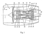
- the gas turbine engine 10 is an example of a turbomachine to which the invention may find application. However, it will be understood from the following that the invention can be used with other turbomachinery as well.
- the engine 10 is conventionally formed and includes in the flow direction one after another an air inlet 11, a fan 12 circulating in a housing, an intermediate pressure compressor 13, a high pressure compressor 14, combustion chambers 15, a high pressure turbine 16, an intermediate pressure turbine 17 and a low pressure turbine 18 and an exhaust nozzle 19, which are all arranged around a central engine axis 1.
- the intermediate pressure compressor 13 and the high pressure compressor 14 each include a plurality of stages, each of which includes a circumferentially extending array of fixed stationary vanes 20, commonly referred to as stator vanes, that radially inwardly from the engine casing 21 in an annular flow passage through the compressors 13, 14 protrude.
- the compressors further include an array of compressor blades 22 projecting radially outwardly from a rotatable drum or disc 26 coupled to hubs 27 of the high pressure turbine 16 and the intermediate pressure turbine 17, respectively.
- the turbine sections 16, 17, 18 have similar steps, comprising an array of fixed vanes 23 extending radially inward from the housing 21 into the housing annular flow channel through the turbines 16, 17, 18 protrude, and a subsequent arrangement of turbine blades 24 which project outwardly from a rotatable hub 27.
- the compressor drum or compressor disk 26 and the vanes 22 disposed thereon and the turbine rotor hub 27 and the turbine blades 24 disposed thereon rotate about the engine axis 1 during operation.
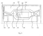
- the Fig. 2 shows in a simplified schematic representation of the area of a combustion chamber 108 of a gas turbine.
- This comprises an inner combustion chamber housing 109 and an outer combustion chamber housing 110.
- a combustion chamber head 107 is arranged, in which a burner 106 with arm and head is arranged.
- a compressor 103 is also connected to the drive shaft 102.
- the reference numeral 104 shows a side stream (bypass channel).
- the incoming air is passed through a compressor outlet guide 105 with diffuser.
- the flow exiting the combustion chamber 108 is performed by a turbine nozzle 111 and a turbine runner 112.
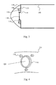
- the Fig. 3 shows a schematic detail view of an embodiment of the inventive solution.
- a base plate 113 is arranged at the upstream end region of the combustion chamber 108, which is provided with a recess which is delimited by a collar 118. Through the recess of the burner 106 is performed, as in the Fig. 1 and 2 is shown.
- the base plate 113 is provided with a projection 114 (thickening).
- the thickening 114 supports in a recess 115 a burner seal 116, which is annular, as known from the prior art.
- the burner seal 116 is held by a retaining element 117 (retaining ring), as described in the following figures.
- the Fig. 4 shows a portion of the annular base plate 113, which is provided with the collar 118 which limits the recess 121 for the passage of the burner 106.
- Distributed around the circumference of the collar 118 are three lugs 114 (thickenings of the base plate 113).
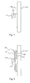
- the Fig. 5 shows a schematic partial side sectional view of the base plate 113 with the collar 118 and a projection 114 with a recess 115.
- Die Fig. 6 shows the in Fig. 5 shown arrangement in the mounted state of the annular burner seal 116 and the retaining element 117 (retaining ring).
- the holding element 117 shows a locking tab (tab) 120, as will be described below.
- the Fig. 6 shows the arrangement of the locking tab 120 at the radially outer region of the retaining ring 117, as in the right half of the Fig. 8 is shown. There are three circumferentially distributed locking tabs (tabs) 120 shown.
- the Fig. 7 shows a variant in which the locking tab 120 is inserted into the recess 115 of the projection 114. It is thus shown the finished assembled state.
- the right half of the picture Fig. 8 shows variants of the locking tabs, namely a locking tab 120a of the seal holder (retaining ring 117).
- the variant of the locking tab 120b is arranged on the outside of the retaining ring 117, while the variant of the locking tab 120c is arranged on the inside of the retaining ring 117.
- the locking tabs 120b and 120c are each shown in the bent state.
Landscapes
- Engineering & Computer Science (AREA)
- Chemical & Material Sciences (AREA)
- Combustion & Propulsion (AREA)
- Mechanical Engineering (AREA)
- General Engineering & Computer Science (AREA)
- Turbine Rotor Nozzle Sealing (AREA)
Applications Claiming Priority (1)
| Application Number | Priority Date | Filing Date | Title |
|---|---|---|---|
| DE102011014972A DE102011014972A1 (de) | 2011-03-24 | 2011-03-24 | Brennkammerkopf mit Halterungen für Dichtungen an Brennern in Gasturbinen |
Publications (3)
| Publication Number | Publication Date |
|---|---|
| EP2503242A2 true EP2503242A2 (fr) | 2012-09-26 |
| EP2503242A3 EP2503242A3 (fr) | 2017-11-08 |
| EP2503242B1 EP2503242B1 (fr) | 2020-03-04 |
Family
ID=45932107
Family Applications (1)
| Application Number | Title | Priority Date | Filing Date |
|---|---|---|---|
| EP12002047.4A Active EP2503242B1 (fr) | 2011-03-24 | 2012-03-22 | Tête pour chambre de combustion avec fixation pour les joints d'étanchéité des brûleurs dans des turbines à gaz |
Country Status (3)
| Country | Link |
|---|---|
| US (1) | US9222675B2 (fr) |
| EP (1) | EP2503242B1 (fr) |
| DE (1) | DE102011014972A1 (fr) |
Cited By (1)
| Publication number | Priority date | Publication date | Assignee | Title |
|---|---|---|---|---|
| DE102013007443A1 (de) | 2013-04-30 | 2014-10-30 | Rolls-Royce Deutschland Ltd & Co Kg | Brennerdichtung für Gasturbinen-Brennkammerkopf und Hitzeschild |
Families Citing this family (7)
| Publication number | Priority date | Publication date | Assignee | Title |
|---|---|---|---|---|
| EP3039344B1 (fr) * | 2013-08-30 | 2018-08-08 | United Technologies Corporation | Interface de montage de coupelle de turbulence pour une chambre de combustion de turbine à gaz |
| GB201321193D0 (en) | 2013-12-02 | 2014-01-15 | Rolls Royce Plc | A combustion chamber assembly |
| FR3015639B1 (fr) * | 2013-12-20 | 2018-08-31 | Safran Aircraft Engines | Chambre de combustion dans une turbomachine |
| GB2543803B (en) * | 2015-10-29 | 2019-10-30 | Rolls Royce Plc | A combustion chamber assembly |
| GB2547906B (en) * | 2016-03-02 | 2019-07-03 | Rolls Royce Plc | A bladed rotor arrangement |
| US11428410B2 (en) | 2019-10-08 | 2022-08-30 | Rolls-Royce Corporation | Combustor for a gas turbine engine with ceramic matrix composite heat shield and seal retainer |
| US11466858B2 (en) | 2019-10-11 | 2022-10-11 | Rolls-Royce Corporation | Combustor for a gas turbine engine with ceramic matrix composite sealing element |
Citations (5)
| Publication number | Priority date | Publication date | Assignee | Title |
|---|---|---|---|---|
| US5419115A (en) | 1994-04-29 | 1995-05-30 | United Technologies Corporation | Bulkhead and fuel nozzle guide assembly for an annular combustion chamber |
| US5463864A (en) | 1993-12-27 | 1995-11-07 | United Technologies Corporation | Fuel nozzle guide for a gas turbine engine combustor |
| DE4427222A1 (de) | 1994-08-01 | 1996-02-08 | Bmw Rolls Royce Gmbh | Hitzeschild für eine Gasturbinen-Brennkammer |
| US5524438A (en) | 1994-12-15 | 1996-06-11 | United Technologies Corporation | Segmented bulkhead liner for a gas turbine combustor |
| DE10048864A1 (de) | 2000-10-02 | 2002-04-11 | Rolls Royce Deutschland | Brennkammerkopf für eine Gasturbine |
Family Cites Families (11)
| Publication number | Priority date | Publication date | Assignee | Title |
|---|---|---|---|---|
| US4870818A (en) * | 1986-04-18 | 1989-10-03 | United Technologies Corporation | Fuel nozzle guide structure and retainer for a gas turbine engine |
| FR2662784B1 (fr) * | 1990-06-05 | 1992-08-14 | Snecma | Ensemble d'injection pour turbomachine, comprenant un bol de prevaporisation. |
| FR2679010B1 (fr) * | 1991-07-10 | 1993-09-24 | Snecma | Chambre de combustion de turbomachine a bols de prevaporisation demontables. |
| US5577379A (en) * | 1994-12-15 | 1996-11-26 | United Technologies Corporation | Fuel nozzle guide retainer assembly |
| US7140189B2 (en) * | 2004-08-24 | 2006-11-28 | Pratt & Whitney Canada Corp. | Gas turbine floating collar |
| US7131273B2 (en) * | 2004-12-17 | 2006-11-07 | General Electric Company | Gas turbine engine carburetor with flat retainer connecting primary and secondary swirlers |
| US7628019B2 (en) * | 2005-03-21 | 2009-12-08 | United Technologies Corporation | Fuel injector bearing plate assembly and swirler assembly |
| US7617689B2 (en) * | 2006-03-02 | 2009-11-17 | Honeywell International Inc. | Combustor dome assembly including retaining ring |
| FR2903171B1 (fr) * | 2006-06-29 | 2008-10-17 | Snecma Sa | Agencement a liaison par crabot pour chambre de combustion de turbomachine |
| US7926280B2 (en) * | 2007-05-16 | 2011-04-19 | Pratt & Whitney Canada Corp. | Interface between a combustor and fuel nozzle |
| US8689563B2 (en) * | 2009-07-13 | 2014-04-08 | United Technologies Corporation | Fuel nozzle guide plate mistake proofing |
-
2011
- 2011-03-24 DE DE102011014972A patent/DE102011014972A1/de not_active Withdrawn
-
2012
- 2012-03-22 EP EP12002047.4A patent/EP2503242B1/fr active Active
- 2012-03-23 US US13/428,633 patent/US9222675B2/en not_active Expired - Fee Related
Patent Citations (5)
| Publication number | Priority date | Publication date | Assignee | Title |
|---|---|---|---|---|
| US5463864A (en) | 1993-12-27 | 1995-11-07 | United Technologies Corporation | Fuel nozzle guide for a gas turbine engine combustor |
| US5419115A (en) | 1994-04-29 | 1995-05-30 | United Technologies Corporation | Bulkhead and fuel nozzle guide assembly for an annular combustion chamber |
| DE4427222A1 (de) | 1994-08-01 | 1996-02-08 | Bmw Rolls Royce Gmbh | Hitzeschild für eine Gasturbinen-Brennkammer |
| US5524438A (en) | 1994-12-15 | 1996-06-11 | United Technologies Corporation | Segmented bulkhead liner for a gas turbine combustor |
| DE10048864A1 (de) | 2000-10-02 | 2002-04-11 | Rolls Royce Deutschland | Brennkammerkopf für eine Gasturbine |
Cited By (3)
| Publication number | Priority date | Publication date | Assignee | Title |
|---|---|---|---|---|
| DE102013007443A1 (de) | 2013-04-30 | 2014-10-30 | Rolls-Royce Deutschland Ltd & Co Kg | Brennerdichtung für Gasturbinen-Brennkammerkopf und Hitzeschild |
| EP2799776A1 (fr) | 2013-04-30 | 2014-11-05 | Rolls-Royce Deutschland Ltd & Co KG | Joint de brûleur pour tête de chambre de combustion de turbines à gaz et bouclier thermique |
| US10041415B2 (en) | 2013-04-30 | 2018-08-07 | Rolls-Royce Deutschland Ltd & Co Kg | Burner seal for gas-turbine combustion chamber head and heat shield |
Also Published As
| Publication number | Publication date |
|---|---|
| US9222675B2 (en) | 2015-12-29 |
| US20120240595A1 (en) | 2012-09-27 |
| DE102011014972A1 (de) | 2012-09-27 |
| EP2503242B1 (fr) | 2020-03-04 |
| EP2503242A3 (fr) | 2017-11-08 |
Similar Documents
| Publication | Publication Date | Title |
|---|---|---|
| EP2503242B1 (fr) | Tête pour chambre de combustion avec fixation pour les joints d'étanchéité des brûleurs dans des turbines à gaz | |
| EP2503246B1 (fr) | Tête de chambre de combustion segmentée | |
| EP3056813B1 (fr) | Joint pour un interstice marginal entre les bardeaux d'effusion d'une chambre de combustion de turbines a gaz | |
| EP2845999B1 (fr) | Procédé d'équilibrage et de montage d'un rotor de turbine | |
| EP2873921A1 (fr) | Élément de blindage contre la chaleur d'une chambre de combustion d'une turbine à gaz | |
| DE102010064047A1 (de) | Strömungsmaschine | |
| EP2799776A1 (fr) | Joint de brûleur pour tête de chambre de combustion de turbines à gaz et bouclier thermique | |
| EP2714518A1 (fr) | Groupe motopropulseur de turbine à gaz muni d'une admission d'air télescopique de l'habillage du groupe motopropulseur | |
| EP3954876B1 (fr) | Couronne directrice pour un turbocompresseur à gaz d'échappement | |
| EP2966352A1 (fr) | Chambre de combustion d'une turbine a gaz dotee de tete de chambre de combustion vissee | |
| EP1573172B1 (fr) | Turbine et procédé de démontage des aubes fixes d'une turbine | |
| DE102011016917A1 (de) | Gasturbinenbrennkammer mit einer Halterung einer Dichtung für ein Anbauteil | |
| EP2980481A1 (fr) | Turbine à gaz d'avion avec un joint d'étanchéité pour l'étanchéificiation d'une bougie d'allumage au niveau de la paroi de la chambre de combustion d'une turbine à gaz | |
| EP2831379B1 (fr) | Anneau de support | |
| EP2730744B1 (fr) | Turbosoufflante de gaz d'échappement | |
| DE102014209057A1 (de) | Gasturbinengehäuseanordnung | |
| EP2781695A1 (fr) | Aubes de guidage d'une turbine à gaz d'échappement | |
| EP3170987B1 (fr) | Système de bague intérieure pour turbomachine | |
| DE102012014109A1 (de) | Zwischenscheibendichtung einer Gasturbine | |
| DE102017201349A1 (de) | Brennkammeranordnung einer Gasturbine | |
| EP3022395B1 (fr) | Elément d'insertion et turbine à gaz | |
| DE102014222320A1 (de) | Brennkammerwand einer Gasturbine mit Kühlung für einen Mischluftlochrand | |
| DE102015213786A1 (de) | Fluggasturbine mit in-situ-Wartungsöffnung mittels demontierbarer Leitschaufel eines Hochdruckkompressors | |
| DE102015224990A1 (de) | Verfahren zur Montage einer Brennkammer eines Gasturbinentriebwerks | |
| DE102015225825A1 (de) | Gasturbinenbrennkammer mit ringförmigem Hitzeschild |
Legal Events
| Date | Code | Title | Description |
|---|---|---|---|
| PUAI | Public reference made under article 153(3) epc to a published international application that has entered the european phase |
Free format text: ORIGINAL CODE: 0009012 |
|
| AK | Designated contracting states |
Kind code of ref document: A2 Designated state(s): AL AT BE BG CH CY CZ DE DK EE ES FI FR GB GR HR HU IE IS IT LI LT LU LV MC MK MT NL NO PL PT RO RS SE SI SK SM TR |
|
| AX | Request for extension of the european patent |
Extension state: BA ME |
|
| PUAL | Search report despatched |
Free format text: ORIGINAL CODE: 0009013 |
|
| AK | Designated contracting states |
Kind code of ref document: A3 Designated state(s): AL AT BE BG CH CY CZ DE DK EE ES FI FR GB GR HR HU IE IS IT LI LT LU LV MC MK MT NL NO PL PT RO RS SE SI SK SM TR |
|
| AX | Request for extension of the european patent |
Extension state: BA ME |
|
| RIC1 | Information provided on ipc code assigned before grant |
Ipc: F23R 3/28 20060101AFI20171005BHEP Ipc: F23R 3/00 20060101ALI20171005BHEP |
|
| RAP1 | Party data changed (applicant data changed or rights of an application transferred) |
Owner name: ROLLS-ROYCE DEUTSCHLAND LTD & CO KG |
|
| STAA | Information on the status of an ep patent application or granted ep patent |
Free format text: STATUS: REQUEST FOR EXAMINATION WAS MADE |
|
| 17P | Request for examination filed |
Effective date: 20180425 |
|
| RBV | Designated contracting states (corrected) |
Designated state(s): AL AT BE BG CH CY CZ DE DK EE ES FI FR GB GR HR HU IE IS IT LI LT LU LV MC MK MT NL NO PL PT RO RS SE SI SK SM TR |
|
| STAA | Information on the status of an ep patent application or granted ep patent |
Free format text: STATUS: EXAMINATION IS IN PROGRESS |
|
| 17Q | First examination report despatched |
Effective date: 20181017 |
|
| GRAP | Despatch of communication of intention to grant a patent |
Free format text: ORIGINAL CODE: EPIDOSNIGR1 |
|
| STAA | Information on the status of an ep patent application or granted ep patent |
Free format text: STATUS: GRANT OF PATENT IS INTENDED |
|
| INTG | Intention to grant announced |
Effective date: 20190918 |
|
| GRAS | Grant fee paid |
Free format text: ORIGINAL CODE: EPIDOSNIGR3 |
|
| GRAA | (expected) grant |
Free format text: ORIGINAL CODE: 0009210 |
|
| STAA | Information on the status of an ep patent application or granted ep patent |
Free format text: STATUS: THE PATENT HAS BEEN GRANTED |
|
| AK | Designated contracting states |
Kind code of ref document: B1 Designated state(s): AL AT BE BG CH CY CZ DE DK EE ES FI FR GB GR HR HU IE IS IT LI LT LU LV MC MK MT NL NO PL PT RO RS SE SI SK SM TR |
|
| REG | Reference to a national code |
Ref country code: GB Ref legal event code: FG4D Free format text: NOT ENGLISH |
|
| RIN1 | Information on inventor provided before grant (corrected) |
Inventor name: GERENDAS, MIKLOS, DR.-ING. |
|
| REG | Reference to a national code |
Ref country code: CH Ref legal event code: EP |
|
| REG | Reference to a national code |
Ref country code: AT Ref legal event code: REF Ref document number: 1240807 Country of ref document: AT Kind code of ref document: T Effective date: 20200315 |
|
| REG | Reference to a national code |
Ref country code: DE Ref legal event code: R096 Ref document number: 502012015822 Country of ref document: DE |
|
| REG | Reference to a national code |
Ref country code: IE Ref legal event code: FG4D Free format text: LANGUAGE OF EP DOCUMENT: GERMAN |
|
| PGFP | Annual fee paid to national office [announced via postgrant information from national office to epo] |
Ref country code: GB Payment date: 20200327 Year of fee payment: 9 |
|
| PG25 | Lapsed in a contracting state [announced via postgrant information from national office to epo] |
Ref country code: FI Free format text: LAPSE BECAUSE OF FAILURE TO SUBMIT A TRANSLATION OF THE DESCRIPTION OR TO PAY THE FEE WITHIN THE PRESCRIBED TIME-LIMIT Effective date: 20200304 Ref country code: NO Free format text: LAPSE BECAUSE OF FAILURE TO SUBMIT A TRANSLATION OF THE DESCRIPTION OR TO PAY THE FEE WITHIN THE PRESCRIBED TIME-LIMIT Effective date: 20200604 Ref country code: RS Free format text: LAPSE BECAUSE OF FAILURE TO SUBMIT A TRANSLATION OF THE DESCRIPTION OR TO PAY THE FEE WITHIN THE PRESCRIBED TIME-LIMIT Effective date: 20200304 |
|
| REG | Reference to a national code |
Ref country code: NL Ref legal event code: MP Effective date: 20200304 |
|
| PG25 | Lapsed in a contracting state [announced via postgrant information from national office to epo] |
Ref country code: HR Free format text: LAPSE BECAUSE OF FAILURE TO SUBMIT A TRANSLATION OF THE DESCRIPTION OR TO PAY THE FEE WITHIN THE PRESCRIBED TIME-LIMIT Effective date: 20200304 Ref country code: SE Free format text: LAPSE BECAUSE OF FAILURE TO SUBMIT A TRANSLATION OF THE DESCRIPTION OR TO PAY THE FEE WITHIN THE PRESCRIBED TIME-LIMIT Effective date: 20200304 Ref country code: GR Free format text: LAPSE BECAUSE OF FAILURE TO SUBMIT A TRANSLATION OF THE DESCRIPTION OR TO PAY THE FEE WITHIN THE PRESCRIBED TIME-LIMIT Effective date: 20200605 Ref country code: LV Free format text: LAPSE BECAUSE OF FAILURE TO SUBMIT A TRANSLATION OF THE DESCRIPTION OR TO PAY THE FEE WITHIN THE PRESCRIBED TIME-LIMIT Effective date: 20200304 Ref country code: BG Free format text: LAPSE BECAUSE OF FAILURE TO SUBMIT A TRANSLATION OF THE DESCRIPTION OR TO PAY THE FEE WITHIN THE PRESCRIBED TIME-LIMIT Effective date: 20200604 |
|
| REG | Reference to a national code |
Ref country code: LT Ref legal event code: MG4D |
|
| PG25 | Lapsed in a contracting state [announced via postgrant information from national office to epo] |
Ref country code: NL Free format text: LAPSE BECAUSE OF FAILURE TO SUBMIT A TRANSLATION OF THE DESCRIPTION OR TO PAY THE FEE WITHIN THE PRESCRIBED TIME-LIMIT Effective date: 20200304 |
|
| PG25 | Lapsed in a contracting state [announced via postgrant information from national office to epo] |
Ref country code: CZ Free format text: LAPSE BECAUSE OF FAILURE TO SUBMIT A TRANSLATION OF THE DESCRIPTION OR TO PAY THE FEE WITHIN THE PRESCRIBED TIME-LIMIT Effective date: 20200304 Ref country code: IS Free format text: LAPSE BECAUSE OF FAILURE TO SUBMIT A TRANSLATION OF THE DESCRIPTION OR TO PAY THE FEE WITHIN THE PRESCRIBED TIME-LIMIT Effective date: 20200704 Ref country code: PT Free format text: LAPSE BECAUSE OF FAILURE TO SUBMIT A TRANSLATION OF THE DESCRIPTION OR TO PAY THE FEE WITHIN THE PRESCRIBED TIME-LIMIT Effective date: 20200729 Ref country code: ES Free format text: LAPSE BECAUSE OF FAILURE TO SUBMIT A TRANSLATION OF THE DESCRIPTION OR TO PAY THE FEE WITHIN THE PRESCRIBED TIME-LIMIT Effective date: 20200304 Ref country code: RO Free format text: LAPSE BECAUSE OF FAILURE TO SUBMIT A TRANSLATION OF THE DESCRIPTION OR TO PAY THE FEE WITHIN THE PRESCRIBED TIME-LIMIT Effective date: 20200304 Ref country code: LT Free format text: LAPSE BECAUSE OF FAILURE TO SUBMIT A TRANSLATION OF THE DESCRIPTION OR TO PAY THE FEE WITHIN THE PRESCRIBED TIME-LIMIT Effective date: 20200304 Ref country code: SM Free format text: LAPSE BECAUSE OF FAILURE TO SUBMIT A TRANSLATION OF THE DESCRIPTION OR TO PAY THE FEE WITHIN THE PRESCRIBED TIME-LIMIT Effective date: 20200304 Ref country code: EE Free format text: LAPSE BECAUSE OF FAILURE TO SUBMIT A TRANSLATION OF THE DESCRIPTION OR TO PAY THE FEE WITHIN THE PRESCRIBED TIME-LIMIT Effective date: 20200304 Ref country code: SK Free format text: LAPSE BECAUSE OF FAILURE TO SUBMIT A TRANSLATION OF THE DESCRIPTION OR TO PAY THE FEE WITHIN THE PRESCRIBED TIME-LIMIT Effective date: 20200304 |
|
| REG | Reference to a national code |
Ref country code: CH Ref legal event code: PL |
|
| REG | Reference to a national code |
Ref country code: DE Ref legal event code: R097 Ref document number: 502012015822 Country of ref document: DE |
|
| REG | Reference to a national code |
Ref country code: BE Ref legal event code: MM Effective date: 20200331 |
|
| PG25 | Lapsed in a contracting state [announced via postgrant information from national office to epo] |
Ref country code: MC Free format text: LAPSE BECAUSE OF FAILURE TO SUBMIT A TRANSLATION OF THE DESCRIPTION OR TO PAY THE FEE WITHIN THE PRESCRIBED TIME-LIMIT Effective date: 20200304 Ref country code: LU Free format text: LAPSE BECAUSE OF NON-PAYMENT OF DUE FEES Effective date: 20200322 |
|
| PLBE | No opposition filed within time limit |
Free format text: ORIGINAL CODE: 0009261 |
|
| STAA | Information on the status of an ep patent application or granted ep patent |
Free format text: STATUS: NO OPPOSITION FILED WITHIN TIME LIMIT |
|
| PG25 | Lapsed in a contracting state [announced via postgrant information from national office to epo] |
Ref country code: DK Free format text: LAPSE BECAUSE OF FAILURE TO SUBMIT A TRANSLATION OF THE DESCRIPTION OR TO PAY THE FEE WITHIN THE PRESCRIBED TIME-LIMIT Effective date: 20200304 Ref country code: CH Free format text: LAPSE BECAUSE OF NON-PAYMENT OF DUE FEES Effective date: 20200331 Ref country code: IE Free format text: LAPSE BECAUSE OF NON-PAYMENT OF DUE FEES Effective date: 20200322 Ref country code: IT Free format text: LAPSE BECAUSE OF FAILURE TO SUBMIT A TRANSLATION OF THE DESCRIPTION OR TO PAY THE FEE WITHIN THE PRESCRIBED TIME-LIMIT Effective date: 20200304 Ref country code: LI Free format text: LAPSE BECAUSE OF NON-PAYMENT OF DUE FEES Effective date: 20200331 |
|
| 26N | No opposition filed |
Effective date: 20201207 |
|
| PG25 | Lapsed in a contracting state [announced via postgrant information from national office to epo] |
Ref country code: SI Free format text: LAPSE BECAUSE OF FAILURE TO SUBMIT A TRANSLATION OF THE DESCRIPTION OR TO PAY THE FEE WITHIN THE PRESCRIBED TIME-LIMIT Effective date: 20200304 Ref country code: BE Free format text: LAPSE BECAUSE OF NON-PAYMENT OF DUE FEES Effective date: 20200331 Ref country code: PL Free format text: LAPSE BECAUSE OF FAILURE TO SUBMIT A TRANSLATION OF THE DESCRIPTION OR TO PAY THE FEE WITHIN THE PRESCRIBED TIME-LIMIT Effective date: 20200304 |
|
| REG | Reference to a national code |
Ref country code: AT Ref legal event code: MM01 Ref document number: 1240807 Country of ref document: AT Kind code of ref document: T Effective date: 20200322 |
|
| PG25 | Lapsed in a contracting state [announced via postgrant information from national office to epo] |
Ref country code: AT Free format text: LAPSE BECAUSE OF NON-PAYMENT OF DUE FEES Effective date: 20200322 |
|
| GBPC | Gb: european patent ceased through non-payment of renewal fee |
Effective date: 20210322 |
|
| PG25 | Lapsed in a contracting state [announced via postgrant information from national office to epo] |
Ref country code: GB Free format text: LAPSE BECAUSE OF NON-PAYMENT OF DUE FEES Effective date: 20210322 |
|
| PGFP | Annual fee paid to national office [announced via postgrant information from national office to epo] |
Ref country code: DE Payment date: 20220329 Year of fee payment: 11 |
|
| PG25 | Lapsed in a contracting state [announced via postgrant information from national office to epo] |
Ref country code: TR Free format text: LAPSE BECAUSE OF FAILURE TO SUBMIT A TRANSLATION OF THE DESCRIPTION OR TO PAY THE FEE WITHIN THE PRESCRIBED TIME-LIMIT Effective date: 20200304 Ref country code: MT Free format text: LAPSE BECAUSE OF FAILURE TO SUBMIT A TRANSLATION OF THE DESCRIPTION OR TO PAY THE FEE WITHIN THE PRESCRIBED TIME-LIMIT Effective date: 20200304 Ref country code: CY Free format text: LAPSE BECAUSE OF FAILURE TO SUBMIT A TRANSLATION OF THE DESCRIPTION OR TO PAY THE FEE WITHIN THE PRESCRIBED TIME-LIMIT Effective date: 20200304 |
|
| PGFP | Annual fee paid to national office [announced via postgrant information from national office to epo] |
Ref country code: FR Payment date: 20220325 Year of fee payment: 11 |
|
| PG25 | Lapsed in a contracting state [announced via postgrant information from national office to epo] |
Ref country code: MK Free format text: LAPSE BECAUSE OF FAILURE TO SUBMIT A TRANSLATION OF THE DESCRIPTION OR TO PAY THE FEE WITHIN THE PRESCRIBED TIME-LIMIT Effective date: 20200304 Ref country code: AL Free format text: LAPSE BECAUSE OF FAILURE TO SUBMIT A TRANSLATION OF THE DESCRIPTION OR TO PAY THE FEE WITHIN THE PRESCRIBED TIME-LIMIT Effective date: 20200304 |
|
| P01 | Opt-out of the competence of the unified patent court (upc) registered |
Effective date: 20230528 |
|
| REG | Reference to a national code |
Ref country code: DE Ref legal event code: R119 Ref document number: 502012015822 Country of ref document: DE |
|
| PG25 | Lapsed in a contracting state [announced via postgrant information from national office to epo] |
Ref country code: FR Free format text: LAPSE BECAUSE OF NON-PAYMENT OF DUE FEES Effective date: 20230331 Ref country code: DE Free format text: LAPSE BECAUSE OF NON-PAYMENT OF DUE FEES Effective date: 20231003 |