EP3954876B1 - Couronne directrice pour un turbocompresseur à gaz d'échappement - Google Patents
Couronne directrice pour un turbocompresseur à gaz d'échappement Download PDFInfo
- Publication number
- EP3954876B1 EP3954876B1 EP21195944.0A EP21195944A EP3954876B1 EP 3954876 B1 EP3954876 B1 EP 3954876B1 EP 21195944 A EP21195944 A EP 21195944A EP 3954876 B1 EP3954876 B1 EP 3954876B1
- Authority
- EP
- European Patent Office
- Prior art keywords
- nozzle ring
- bearing housing
- turbine
- housing
- main body
- Prior art date
- Legal status (The legal status is an assumption and is not a legal conclusion. Google has not performed a legal analysis and makes no representation as to the accuracy of the status listed.)
- Active
Links
Images



Classifications
-
- F—MECHANICAL ENGINEERING; LIGHTING; HEATING; WEAPONS; BLASTING
- F02—COMBUSTION ENGINES; HOT-GAS OR COMBUSTION-PRODUCT ENGINE PLANTS
- F02C—GAS-TURBINE PLANTS; AIR INTAKES FOR JET-PROPULSION PLANTS; CONTROLLING FUEL SUPPLY IN AIR-BREATHING JET-PROPULSION PLANTS
- F02C6/00—Plural gas-turbine plants; Combinations of gas-turbine plants with other apparatus; Adaptations of gas-turbine plants for special use
- F02C6/04—Gas-turbine plants providing heated or pressurised working fluid for other apparatus, e.g. without mechanical power output
- F02C6/10—Gas-turbine plants providing heated or pressurised working fluid for other apparatus, e.g. without mechanical power output supplying working fluid to a user, e.g. a chemical process, which returns working fluid to a turbine of the plant
- F02C6/12—Turbochargers, i.e. plants for augmenting mechanical power output of internal-combustion piston engines by increase of charge pressure
-
- F—MECHANICAL ENGINEERING; LIGHTING; HEATING; WEAPONS; BLASTING
- F01—MACHINES OR ENGINES IN GENERAL; ENGINE PLANTS IN GENERAL; STEAM ENGINES
- F01D—NON-POSITIVE DISPLACEMENT MACHINES OR ENGINES, e.g. STEAM TURBINES
- F01D17/00—Regulating or controlling by varying flow
- F01D17/10—Final actuators
- F01D17/12—Final actuators arranged in stator parts
- F01D17/14—Final actuators arranged in stator parts varying effective cross-sectional area of nozzles or guide conduits
- F01D17/16—Final actuators arranged in stator parts varying effective cross-sectional area of nozzles or guide conduits by means of nozzle vanes
- F01D17/165—Final actuators arranged in stator parts varying effective cross-sectional area of nozzles or guide conduits by means of nozzle vanes for radial flow, i.e. the vanes turning around axes which are essentially parallel to the rotor centre line
-
- F—MECHANICAL ENGINEERING; LIGHTING; HEATING; WEAPONS; BLASTING
- F01—MACHINES OR ENGINES IN GENERAL; ENGINE PLANTS IN GENERAL; STEAM ENGINES
- F01D—NON-POSITIVE DISPLACEMENT MACHINES OR ENGINES, e.g. STEAM TURBINES
- F01D25/00—Component parts, details, or accessories, not provided for in, or of interest apart from, other groups
- F01D25/16—Arrangement of bearings; Supporting or mounting bearings in casings
-
- F—MECHANICAL ENGINEERING; LIGHTING; HEATING; WEAPONS; BLASTING
- F01—MACHINES OR ENGINES IN GENERAL; ENGINE PLANTS IN GENERAL; STEAM ENGINES
- F01D—NON-POSITIVE DISPLACEMENT MACHINES OR ENGINES, e.g. STEAM TURBINES
- F01D25/00—Component parts, details, or accessories, not provided for in, or of interest apart from, other groups
- F01D25/24—Casings; Casing parts, e.g. diaphragms, casing fastenings
- F01D25/246—Fastening of diaphragms or stator-rings
-
- F—MECHANICAL ENGINEERING; LIGHTING; HEATING; WEAPONS; BLASTING
- F01—MACHINES OR ENGINES IN GENERAL; ENGINE PLANTS IN GENERAL; STEAM ENGINES
- F01D—NON-POSITIVE DISPLACEMENT MACHINES OR ENGINES, e.g. STEAM TURBINES
- F01D5/00—Blades; Blade-carrying members; Heating, heat-insulating, cooling or antivibration means on the blades or the members
- F01D5/02—Blade-carrying members, e.g. rotors
- F01D5/04—Blade-carrying members, e.g. rotors for radial-flow machines or engines
- F01D5/043—Blade-carrying members, e.g. rotors for radial-flow machines or engines of the axial inlet- radial outlet, or vice versa, type
- F01D5/046—Heating, heat insulation or cooling means
-
- F—MECHANICAL ENGINEERING; LIGHTING; HEATING; WEAPONS; BLASTING
- F05—INDEXING SCHEMES RELATING TO ENGINES OR PUMPS IN VARIOUS SUBCLASSES OF CLASSES F01-F04
- F05D—INDEXING SCHEME FOR ASPECTS RELATING TO NON-POSITIVE-DISPLACEMENT MACHINES OR ENGINES, GAS-TURBINES OR JET-PROPULSION PLANTS
- F05D2220/00—Application
- F05D2220/40—Application in turbochargers
-
- F—MECHANICAL ENGINEERING; LIGHTING; HEATING; WEAPONS; BLASTING
- F05—INDEXING SCHEMES RELATING TO ENGINES OR PUMPS IN VARIOUS SUBCLASSES OF CLASSES F01-F04
- F05D—INDEXING SCHEME FOR ASPECTS RELATING TO NON-POSITIVE-DISPLACEMENT MACHINES OR ENGINES, GAS-TURBINES OR JET-PROPULSION PLANTS
- F05D2240/00—Components
- F05D2240/10—Stators
- F05D2240/15—Heat shield
-
- F—MECHANICAL ENGINEERING; LIGHTING; HEATING; WEAPONS; BLASTING
- F05—INDEXING SCHEMES RELATING TO ENGINES OR PUMPS IN VARIOUS SUBCLASSES OF CLASSES F01-F04
- F05D—INDEXING SCHEME FOR ASPECTS RELATING TO NON-POSITIVE-DISPLACEMENT MACHINES OR ENGINES, GAS-TURBINES OR JET-PROPULSION PLANTS
- F05D2260/00—Function
- F05D2260/30—Retaining components in desired mutual position
- F05D2260/38—Retaining components in desired mutual position by a spring, i.e. spring loaded or biased towards a certain position
-
- Y—GENERAL TAGGING OF NEW TECHNOLOGICAL DEVELOPMENTS; GENERAL TAGGING OF CROSS-SECTIONAL TECHNOLOGIES SPANNING OVER SEVERAL SECTIONS OF THE IPC; TECHNICAL SUBJECTS COVERED BY FORMER USPC CROSS-REFERENCE ART COLLECTIONS [XRACs] AND DIGESTS
- Y02—TECHNOLOGIES OR APPLICATIONS FOR MITIGATION OR ADAPTATION AGAINST CLIMATE CHANGE
- Y02T—CLIMATE CHANGE MITIGATION TECHNOLOGIES RELATED TO TRANSPORTATION
- Y02T10/00—Road transport of goods or passengers
- Y02T10/10—Internal combustion engine [ICE] based vehicles
- Y02T10/12—Improving ICE efficiencies
Definitions
- the invention relates to the field of exhaust gas turbochargers for supercharged internal combustion engines.
- the invention relates to a nozzle ring for a radial turbine of such an exhaust gas turbocharger
- exhaust gas turbochargers are used as standard to increase the performance of an internal combustion engine. They have a turbine in the exhaust system of the internal combustion engine and a compressor upstream of the internal combustion engine. The exhaust gases from the internal combustion engine are expanded in the turbine. The work gained is transferred to the compressor via a shaft, which compresses the air supplied to the internal combustion engine. By using the energy from the exhaust gases to compress the air supplied to the combustion process in the internal combustion engine, the combustion process and the efficiency of the internal combustion engine can be optimized.
- the kinetic energy of the exhaust gas is used to drive the rotor of the turbocharger.
- the exhaust gas jet must be directed precisely onto the turbine shaft.
- a nozzle ring is installed at the outlet of the flow channel in front of the turbine shaft in radial turbine stages.
- nozzle rings of exhaust gas turbochargers are typically subjected to high stress due to changing operating conditions, i.e. increasing or decreasing the pressure and temperature of the working medium, and can be subject to relatively strong thermal expansion.
- Nozzle rings are often attached by simply clamping them into the exhaust turbine housing.
- the nozzle ring can be held in position by clamping it axially, usually between the turbine housing and the bearing housing.
- a separate heat shield can also be installed if the heat input from the exhaust gas into the bearing housing is too high or if too much energy is extracted from the exhaust gas by heat input into adjacent components.
- the object of the present invention is to provide an improved nozzle ring which at least partially, or largely or even completely overcomes the disadvantages known from the prior art.
- a nozzle ring for a radial turbine is provided according to independent claim 1. Further aspects, advantages and features of the present invention can be taken from the dependent claims, the description and the accompanying figures.
- a nozzle ring for a radial turbine comprises a rotationally symmetrical, disk-shaped base body with a central opening for the passage of a shaft.
- the nozzle ring also comprises guide vanes which are arranged in the circumferential direction in a radially outer region of the base body and are designed to guide exhaust gases onto rotor blades of a turbine wheel.
- the guide vanes extend from the base body in the axial direction.
- the base body of the nozzle ring is designed to form a heat shield between a bearing space of a bearing housing and a turbine space in the assembled state.
- the nozzle ring comprises a fastening flange which is arranged in a radially inner region of the base body.
- the fastening flange has a contact surface for resting on a corresponding contact surface of the bearing housing.
- the fastening flange comprises one or more bores arranged in the circumferential direction for receiving one or more fastening means in order to mount the nozzle ring on the bearing housing.
- the disk-shaped base body of the nozzle ring extends radially outwards from the central opening to the radially outer region in which the guide vanes are arranged.
- the radially outer region comprises the recesses.
- the guide vanes are formed integrally with the disk-shaped base body in the region of the recesses.
- a nozzle ring is advantageously provided which enables a fastening and mounting concept with which the positioning of the nozzle ring blades and the introduction of different turbine rear wall geometries is/are independent of the clamping connection used and/or an existing hot centering/sealing.
- a nozzle ring with an integrated heat shield is advantageously provided, so that the number of interfaces/joints is reduced. Furthermore, the rear wall geometry of the turbine shaft can be cleared/exposed because it is integrated in the nozzle ring, so that no different bearing housing variants are necessary.
- a nozzle ring is provided, the fixation of which can advantageously take place outside the clamping connection "bearing housing/turbine housing", for example by fastening it to the bearing housing using temperature-resistant screws.
- the nozzle ring described here enables an improved connection, in particular with regard to deformation (under the influence of temperature) and gas tightness, since the nozzle ring can advantageously be slightly preloaded axially on the bearing housing like a disc spring.
- an additional "containment" interface can advantageously be avoided.
- an additional interface that affects the gas tightness to the outside can advantageously be avoided.
- the scaling of the turbine head does not affect the clamping connection/hot centering.
- the maximum scaling is defined by dimensioning the bearing housing.
- the nozzle ring described here can advantageously be fastened to the bearing housing in a central area around the turbine shaft, so that thermal expansion of the nozzle ring is advantageously little influenced by a fastening located relatively far inside.
- a further advantage of the nozzle ring described here is that the fastening elements for the nozzle ring are not located in the area of the main flow.
- an exhaust gas turbocharger with a nozzle ring according to one of the embodiments described herein is provided, so that an improved exhaust gas turbocharger can advantageously be provided.
- the exhaust gas turbocharger comprises a turbine housing, a shaft mounted in a bearing housing, on which a turbine wheel with rotor blades is arranged.
- the exhaust gas turbocharger also comprises an inflow channel for exhaust gases, which is formed in the turbine housing, upstream of the turbine wheel.
- the exhaust gas turbocharger comprises a nozzle ring according to one of the embodiments described herein, wherein the nozzle ring is designed such that the nozzle ring is held axially in the assembled state between the bearing housing and the turbine housing of the exhaust gas turbocharger.
- the nozzle ring is fastened to the bearing housing via the fastening flange by means of heat-resistant fastening means.
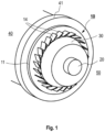
- Figure 1 is a schematic isometric view of a nozzle ring 10 according to embodiments described herein in an assembled state.
- the turbine wheel 30 of a radial turbine is shown schematically.
- the nozzle ring 10 comprises a rotationally symmetrical, disk-shaped base body 11 with a central opening 12 for the passage of a shaft 20.
- the nozzle ring 10 typically comprises guide vanes 14 which are arranged in the circumferential direction in a radially outer region of the base body 11.
- the guide vanes 14 are arranged and designed to guide exhaust gases onto rotor blades of a turbine wheel 30.
- the guide vanes 14 extend from the base body 11 in the axial direction, being integrally formed with the base body.
- the base body 11 of the nozzle ring described here is designed to form a heat shield between a bearing chamber 40 of a bearing housing 41 and a turbine chamber 50 in the assembled state.
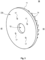
- the base body 11 of the nozzle ring extends radially outward from the central opening 12, as is shown by way of example in the Figures 3 to 5
- the base body of the nozzle ring is designed such that (apart from the holes 17) a closed surface is provided between the central opening 12 and the outer edge of the base body.
- a bearing housing side 11A of the base body 11 comprises one or more recesses 18 in order to form one or more air-filled insulation spaces in the assembled state of the nozzle ring 10, as is the case, for example, in Figure 4
- the nozzle ring comprises a fastening flange 15 which is arranged in a radially inner region of the base body 11.
- the fastening flange 15 has a contact surface 16 for resting on a corresponding contact surface of the bearing housing 41, as shown by way of example in Figure 6 is shown.
- the fastening flange 15 comprises one or more bores 17 arranged in the circumferential direction for receiving one or more fastening means in order to mount the nozzle ring on the bearing housing.
- the disk-shaped base body 11 of the nozzle ring extends from the central opening 12 radially outwards to the radially outer region in which the guide vanes 14 are arranged.
- the radially outer region comprises the recesses 18.
- the guide vanes 14 are formed integrally with the disk-shaped base body (11) in the region of the recesses 18.
- a nozzle ring is provided, the fixing of which can advantageously take place outside the clamping connection "bearing housing/turbine housing", for example by fastening it to the bearing housing using temperature-resistant screws, as described below described.
- the nozzle ring 10 in particular the base body of the nozzle ring, according to embodiments described herein comprises one or more circumferentially arranged bores 17 which are suitable for receiving one or more fastening means for mounting the nozzle ring on the bearing housing.
- the fastening means can be pins, bolts, screws or the like.
- the fastening means are heat-resistant.
- the nozzle ring described here can advantageously be fastened to the bearing housing in a central area around the turbine shaft, so that thermal expansion of the nozzle ring is advantageously little influenced by a fastening located relatively far inside. Furthermore, the fastening of the nozzle ring described here has the advantage that the fastening elements for the nozzle ring are not located in the area of the main flow.
- the fastening flange 15 is an integral part of the base body 11. This advantageously leads to a reduction in component parts.
- the nozzle ring can be designed, alternatively or in addition to a central fastening (e.g. by means of a fastening flange described herein and corresponding fastening means), such that the nozzle ring in the assembled state is clamped axially between the bearing housing 40 and the turbine housing and/or radially in the bearing housing 40 and/or radially in the turbine housing under temperature.
- a central fastening e.g. by means of a fastening flange described herein and corresponding fastening means
- the one or more recesses 18 can comprise ribs 19 extending in the radial direction, as shown by way of example in Figure 5 Such ribs can have a beneficial effect on the stability as well as on the thermal expansion behavior of the nozzle ring.
- the holes 17 in the mounting flange can be arranged on a first virtual circular line with a first radius R1 around the central opening 12.
- the guide vanes 14 can be arranged on a second virtual circular line with a second radius R2 around the central opening 12.
- the second radius R2 is larger than the first radius R1, for example, the second radius R2 can be ⁇ 1.5 ⁇ R1.
- the holes 17 for receiving one or more fastening means in the fastening flange can be arranged at regular or irregular angular intervals around the central opening 12.
- a regular arrangement can, for example, have the advantage of an improved frictional fastening of the nozzle ring to the bearing housing.
- the Nozzle ring can also be a closed nozzle ring.
- the nozzle ring can have a further arranged disk on a side opposite the base body 11, which is connected to the guide vanes 14.
- the further arranged disk can be configured to provide a further heat shield.
- a radially outer region of the base body can have one or more centering cams (not shown) that are distributed along the circumference of the base body.
- Such centering cams can, for example, engage in corresponding grooves in the turbine housing, resulting in radial guidance of the turbine housing with respect to the base body of the nozzle ring.
- the base body of the nozzle ring which is aligned accordingly due to the centering cams, can be pushed into the turbine housing in the axial direction.
- the base body of the nozzle ring expands in the radial direction, and the outer edge of the base body of the nozzle ring is pressed against a corresponding support of the turbine housing, thereby enabling the turbine housing to be centered with respect to the bearing housing.
- the embodiments described herein provide a nozzle ring that can advantageously be used for an exhaust gas turbocharger, so that the positioning of the nozzle ring blades and the introduction of different turbine rear wall geometries is/are independent of the clamping connection used and/or an existing hot centering/sealing.
- the heat shield can be geometrically integrated into an open nozzle ring as an extension of the bearing housing side Nozzle ring plate can be integrated.
- This nozzle ring plate (also referred to as the base body) is designed in such a way that the rear area of the turbine head up to the transition of the shaft hub is covered. This makes it possible to integrate different turbine rear walls and only one specification part is required.
- the nozzle ring blades are integrally formed with the nozzle ring plate and can be produced, for example, by machining or by means of precision casting.
- the nozzle ring can be attached to a relatively small diameter behind the turbine head (turbine head rear space) using fastening means, e.g. screws.
- the nozzle ring is thus located outside the clamped connection of the turbine housing/bearing housing and the fastening means are located in an area that is not critical for the scaling of the turbine head/nozzle ring blades. Removing the nozzle ring from the clamped connection also has a positive effect when considering containment and gas tightness, as the number of interfaces in the clamped connection is reduced.
- This type of assembly allows the nozzle ring to be installed slightly pre-tensioned if necessary (disc spring principle). This measure can counteract thermal deformation. This also helps prevent an "internal gas bypass" behind the nozzle ring.
- FIG 6 is a schematic sectional view of a section of an exhaust gas turbocharger 60 according to embodiments described herein.
- the exhaust gas turbocharger 60 comprises a turbine housing 51, a shaft 20 mounted in a bearing housing 41.
- a turbine wheel 30 with rotor blades 31 is arranged on the shaft 20.
- the exhaust gas turbocharger typically has an inflow channel 33 for exhaust gases which is formed in the turbine housing 51, upstream of the turbine wheel 30.
- the exhaust gas turbocharger has a nozzle ring 10 according to one of the embodiments described herein, as shown schematically in Figure 6 is shown.
- the nozzle ring 10 is designed such that the nozzle ring is held axially in the assembled state between the bearing housing 41 and the turbine housing 51 of the exhaust gas turbocharger.
- the nozzle ring 10 is fastened to the bearing housing 41 via a fastening flange 15 by means of heat-resistant fastening means 15A.
- the heat-resistant fastening means 15A can be heat-resistant screws with which the nozzle ring 10 is screwed to the bearing housing 41.
- the nozzle ring 10 and the bearing housing 41 can be designed such that the nozzle ring is axially clamped in the manner of a disc spring between the bearing housing and the turbine housing in the mounted state.
- the nozzle ring 10 and the bearing housing 41 can be designed as an alternative or additional mounting option for the nozzle ring in the exhaust gas turbocharger in such a way that the nozzle ring 10 in the mounted state is clamped axially between the bearing housing 41 and the turbine housing and/or radially in the bearing housing 41 and/or in the turbine housing 51 under temperature, i.e. heat.
- one or more anti-twisting devices can be provided for the nozzle ring.
- the nozzle ring 10 and the bearing housing 41 can be designed in such a way that one or more anti-twisting devices are provided for the nozzle ring in the assembled state between the nozzle ring 10 and the bearing housing 41 or between the nozzle ring 10 and the turbine housing 51.
- the one or more anti-twisting devices can be provided, for example, by means of positive/non-positive Connections between the nozzle ring and the bearing housing can be implemented.
- one or more anti-twisting devices can be implemented between the nozzle ring and the turbine housing, for example by means of positive/non-positive connections. This can be particularly advantageous if the nozzle ring is not attached to the bearing housing, but is clamped axially between the bearing housing and the turbine housing like a disc spring.
Landscapes
- Engineering & Computer Science (AREA)
- Mechanical Engineering (AREA)
- General Engineering & Computer Science (AREA)
- Chemical & Material Sciences (AREA)
- Chemical Kinetics & Catalysis (AREA)
- General Chemical & Material Sciences (AREA)
- Combustion & Propulsion (AREA)
- Supercharger (AREA)
- Turbine Rotor Nozzle Sealing (AREA)
Claims (12)
- Anneau de buses (10) pour une turbine radiale, comprenant :- un corps de base (11) en forme de disque à symétrie de révolution avec une ouverture centrale (12) pour le passage d'un arbre (20),- des aubes directrices (14) qui sont agencées dans la direction circonférentielle dans une zone radialement extérieure du corps de base (11) et qui sont conçues pour diriger les gaz d'échappement sur des aubes mobiles (31) d'une roue de turbine (30), les aubes directrices (14) s'étendant depuis le corps de base (11) dans la direction axiale,le corps de base (11) étant conçu pour former, à l'état assemblé, un bouclier thermique entre un espace de palier (40) d'un boîtier de palier (41) et un espace de turbine (50), un côté (11A) de boîtier de palier du corps de base (11) comprenant un ou plusieurs évidements (18) pour former, à l'état assemblé de l'anneau de buses (10), un ou plusieurs espaces d'isolation remplis d'air,l'anneau de buses comprenant une bride de fixation (15) qui est agencée dans une zone radialement intérieure du corps de base (11), et la bride de fixation (15) présentant une surface de contact (16) pour un appui sur une surface de contact correspondante du boîtier de palier (41), etla bride de fixation (15) comprenant un ou plusieurs alésages (17) agencés dans la direction circonférentielle pour recevoir un ou plusieurs moyens de fixation, afin de monter l'anneau de buses sur le boîtier de palier,caractérisé en ce quele corps de base (11) en forme de disque de l'anneau de buses s'étend radialement vers l'extérieur depuis l'ouverture centrale (12) jusqu'à la zone radialement extérieure dans laquelle sont agencées les aubes directrices (14), et en ce que la zone radialement extérieure comprend les évidements (8), et en ce que les aubes directrices (14) sont réalisées d'un seul tenant avec le corps de base (11) en forme de disque dans la zone des évidements.
- Anneau de buses (10) selon la revendication 1, dans lequel la bride de fixation (15) est une partie intégrante du corps de base (11).
- Anneau de buses (10) selon l'une des revendications 1 à 2, l'anneau de buses (10) étant conçu de telle sorte qu'à l'état assemblé, l'anneau de buses soit bloqué sous l'effet de la température, axialement entre le boîtier de palier (40) et le boîtier de turbine et/ou radialement dans le boîtier de palier (40) et/ou radialement dans le boîtier de turbine.
- Anneau de buses (10) selon l'une des revendications 1 à 3, dans lequel le ou les évidements (18) comprennent des nervures (19) s'étendant dans la direction radiale.
- Anneau de buses (10) selon l'une des revendications 1 à 4, dans lequel les alésages (17) dans la bride de fixation sont agencés sur une première ligne circulaire virtuelle avec un premier rayon R1 autour de l'ouverture centrale (12), et dans lequel les aubes directrices (14) sont agencées sur une deuxième ligne circulaire virtuelle avec un deuxième rayon R2 autour de l'ouverture centrale (12), le deuxième rayon R2 étant ≥ 1.5×R1.
- Anneau de buses (10) selon l'une des revendications 1 à 5, dans lequel les alésages (17) destinés à recevoir les moyens de fixation dans la bride de fixation sont agencés à intervalles angulaires réguliers autour de l'ouverture centrale (12).
- Anneau de buses (10) selon l'une des revendications 1 à 6, dans lequel un autre disque est agencé sur une face opposée au corps de base (11), ce disque étant relié aux aubes directrices (14).
- Turbocompresseur (60) pour gaz d'échappement, comprenant :- un boîtier de turbine (51),- un arbre (20) logé dans un boîtier de palier (40), sur lequel est agencée une roue de turbine (30) avec des aubes mobiles (31),- un canal d'admission (33) pour les gaz d'échappement, qui est formé dans le boîtier de turbine (51), en amont de la roue de turbine (30), et- un anneau de buses (10) selon l'une des revendications 1 à 7, l'anneau de buses (10) étant conçu de telle sorte que l'anneau de buses est maintenu axialement à l'état assemblé entre le boîtier de palier (41) et le boîtier de turbine (51) du turbocompresseur (60) pour gaz d'échappement, l'anneau de buses étant fixé au boîtier de palier (41) par l'intermédiaire de la bride de fixation (15) en utilisant des moyens de fixation (15A) résistant à la chaleur.
- Turbocompresseur (60) pour gaz d'échappement selon la revendication 8, dans lequel les moyens de fixation (15A) résistants à la chaleur sont des vis résistantes à la chaleur et l'anneau de buses (10) est vissé sur le boîtier de palier (41).
- Turbocompresseur (60) pour gaz d'échappement selon l'une des revendications 8 à 9, dans lequel l'anneau de buses (10) et le boîtier de palier (41) sont conçus de telle sorte que l'anneau de buses (10) soit serré axialement à la manière d'une rondelle à ressort entre le boîtier de palier (41) et le boîtier de turbine (51) à l'état assemblé.
- Turbocompresseur (60) pour gaz d'échappement selon l'une des revendications 8 à 10, dans lequel l'anneau de buses (10) et le boîtier de palier (41) sont conçus de telle sorte qu'à l'état assemblé, sous l'effet de la température, l'anneau de buses soit bloqué axialement entre le boîtier de palier (41) et le boîtier de turbine et/ou radialement dans le boîtier de palier (41) et/ou dans le boîtier de turbine (51).
- Turbocompresseur (60) pour gaz d'échappement selon l'une des revendications 8 à 11, dans lequel un ou plusieurs dispositifs anti-rotation sont prévus pour l'anneau de buses (10) entre l'anneau de buses (10) et le boîtier de palier (41) ou entre l'anneau de buses (10) et le boîtier de turbine (51).
Applications Claiming Priority (3)
| Application Number | Priority Date | Filing Date | Title |
|---|---|---|---|
| DE102017108057.0A DE102017108057A1 (de) | 2017-04-13 | 2017-04-13 | Düsenring für einen abgasturbolader |
| EP18718134.2A EP3610135A1 (fr) | 2017-04-13 | 2018-04-12 | Couronne directrice pour un turbocompresseur à gaz d'échappement |
| PCT/EP2018/059439 WO2018189319A1 (fr) | 2017-04-13 | 2018-04-12 | Couronne directrice pour un turbocompresseur à gaz d'échappement |
Related Parent Applications (1)
| Application Number | Title | Priority Date | Filing Date |
|---|---|---|---|
| EP18718134.2A Division EP3610135A1 (fr) | 2017-04-13 | 2018-04-12 | Couronne directrice pour un turbocompresseur à gaz d'échappement |
Publications (3)
| Publication Number | Publication Date |
|---|---|
| EP3954876A1 EP3954876A1 (fr) | 2022-02-16 |
| EP3954876B1 true EP3954876B1 (fr) | 2024-12-04 |
| EP3954876B8 EP3954876B8 (fr) | 2025-01-08 |
Family
ID=62002127
Family Applications (2)
| Application Number | Title | Priority Date | Filing Date |
|---|---|---|---|
| EP21195944.0A Active EP3954876B8 (fr) | 2017-04-13 | 2018-04-12 | Couronne directrice pour un turbocompresseur à gaz d'échappement |
| EP18718134.2A Withdrawn EP3610135A1 (fr) | 2017-04-13 | 2018-04-12 | Couronne directrice pour un turbocompresseur à gaz d'échappement |
Family Applications After (1)
| Application Number | Title | Priority Date | Filing Date |
|---|---|---|---|
| EP18718134.2A Withdrawn EP3610135A1 (fr) | 2017-04-13 | 2018-04-12 | Couronne directrice pour un turbocompresseur à gaz d'échappement |
Country Status (8)
| Country | Link |
|---|---|
| US (1) | US11313275B2 (fr) |
| EP (2) | EP3954876B8 (fr) |
| JP (1) | JP7130665B2 (fr) |
| KR (1) | KR102554216B1 (fr) |
| CN (1) | CN110475945B (fr) |
| CA (1) | CA3058826A1 (fr) |
| DE (1) | DE102017108057A1 (fr) |
| WO (1) | WO2018189319A1 (fr) |
Families Citing this family (5)
| Publication number | Priority date | Publication date | Assignee | Title |
|---|---|---|---|---|
| EP3927947B1 (fr) | 2019-02-21 | 2024-04-03 | Turbo Systems Switzerland Ltd. | Couronne directrice pour turbine radiale et turbocompresseur de gaz d'échappement correspondant |
| JP7424752B2 (ja) * | 2019-03-25 | 2024-01-30 | 株式会社豊田自動織機 | ターボチャージャ |
| GB2597732A (en) * | 2020-07-31 | 2022-02-09 | Cummins Ltd | Turbine housing |
| US11530615B1 (en) * | 2022-03-01 | 2022-12-20 | Garrett Transportation I Inc. | Method for constructing a fixed-vane ring for a nozzle of a turbocharger turbine |
| JP1802599S (ja) * | 2024-01-17 | 2025-07-01 | ターボチャージャーのノズルリング |
Family Cites Families (23)
| Publication number | Priority date | Publication date | Assignee | Title |
|---|---|---|---|---|
| US4969805A (en) * | 1989-05-02 | 1990-11-13 | Allied-Signal Inc. | Unidirectional turbocharger assembly |
| EP0571205B1 (fr) * | 1992-05-21 | 1997-03-05 | Alliedsignal Limited | Turbosoufflante réglable |
| GB9222133D0 (en) | 1992-10-21 | 1992-12-02 | Leavesley Malcolm G | Turbocharger apparatus |
| DE4238550A1 (de) * | 1992-11-14 | 1994-05-19 | Daimler Benz Ag | Abgasturbolader für eine Brennkraftmaschine |
| DE4330487C1 (de) * | 1993-09-09 | 1995-01-26 | Daimler Benz Ag | Abgasturbolader für eine Brennkraftmaschine |
| DE19615237C2 (de) * | 1996-04-18 | 1999-10-28 | Daimler Chrysler Ag | Abgasturbolader für eine Brennkraftmaschine |
| DE19838754C1 (de) * | 1998-08-26 | 2000-03-09 | Daimler Chrysler Ag | Abgasturbolader für eine Brennkraftmaschine |
| DE10048105A1 (de) * | 2000-09-28 | 2002-04-11 | Daimler Chrysler Ag | Angasturbolader für eine Brennkraftmaschine mit variabler Turbinengeometrie |
| AU2001221812A1 (en) | 2000-11-30 | 2002-06-11 | Honeywell Garrett Sa | Variable geometry turbocharger with sliding piston |
| GB0121864D0 (en) | 2001-09-10 | 2001-10-31 | Leavesley Malcolm G | Turbocharger apparatus |
| JP2003227344A (ja) * | 2001-11-28 | 2003-08-15 | Hitachi Ltd | ターボチャージャ |
| GB0227473D0 (en) | 2002-11-25 | 2002-12-31 | Leavesley Malcolm G | Variable turbocharger apparatus with bypass apertures |
| DE10256418A1 (de) * | 2002-12-02 | 2004-06-09 | Abb Turbo Systems Ag | Abgasturbinengehäuse |
| AU2003206002A1 (en) * | 2003-02-19 | 2004-09-09 | Honeywell International Inc. | Turbine having variable throat |
| US7631497B2 (en) * | 2005-04-21 | 2009-12-15 | Borgwarner Inc. | Turbine heat shield with ribs |
| GB0724022D0 (en) * | 2007-12-07 | 2008-01-16 | Cummins Turbo Tech Ltd | Compressor |
| JP2012107527A (ja) | 2010-11-15 | 2012-06-07 | Ihi Corp | ターボチャージャ |
| EP2455590A1 (fr) * | 2010-11-18 | 2012-05-23 | Fiat Powertrain Technologies S.p.A. | Distributeur à géométrie variable pour turbine, particulièrement pour un ensemble de turbocompresseur de véhicule à moteur |
| WO2013148486A1 (fr) * | 2012-03-30 | 2013-10-03 | Borgwarner Inc. | Corps de palier de turbocompresseur à bouclier thermique intégré |
| KR20140063474A (ko) * | 2012-11-16 | 2014-05-27 | 에이비비 터보 시스템즈 아게 | 노즐 링 |
| EP2778349A1 (fr) | 2013-03-15 | 2014-09-17 | Continental Automotive GmbH | Turbosoufflante de gaz d'échappement avec boîtier de turbine traité |
| JP6349745B2 (ja) * | 2014-01-29 | 2018-07-04 | 株式会社Ihi | 可変ノズルユニット及び可変容量型過給機 |
| US9732633B2 (en) * | 2015-03-09 | 2017-08-15 | Caterpillar Inc. | Turbocharger turbine assembly |
-
2017
- 2017-04-13 DE DE102017108057.0A patent/DE102017108057A1/de not_active Withdrawn
-
2018
- 2018-04-12 EP EP21195944.0A patent/EP3954876B8/fr active Active
- 2018-04-12 US US16/604,833 patent/US11313275B2/en active Active
- 2018-04-12 WO PCT/EP2018/059439 patent/WO2018189319A1/fr not_active Ceased
- 2018-04-12 CN CN201880024713.8A patent/CN110475945B/zh active Active
- 2018-04-12 KR KR1020197030770A patent/KR102554216B1/ko active Active
- 2018-04-12 EP EP18718134.2A patent/EP3610135A1/fr not_active Withdrawn
- 2018-04-12 CA CA3058826A patent/CA3058826A1/fr active Pending
- 2018-04-12 JP JP2019555775A patent/JP7130665B2/ja active Active
Also Published As
| Publication number | Publication date |
|---|---|
| EP3954876A1 (fr) | 2022-02-16 |
| KR20190138802A (ko) | 2019-12-16 |
| EP3954876B8 (fr) | 2025-01-08 |
| US11313275B2 (en) | 2022-04-26 |
| CN110475945A (zh) | 2019-11-19 |
| KR102554216B1 (ko) | 2023-07-12 |
| CN110475945B (zh) | 2023-04-21 |
| DE102017108057A1 (de) | 2018-10-18 |
| CA3058826A1 (fr) | 2018-10-18 |
| JP2020516810A (ja) | 2020-06-11 |
| JP7130665B2 (ja) | 2022-09-05 |
| EP3610135A1 (fr) | 2020-02-19 |
| US20200392895A1 (en) | 2020-12-17 |
| WO2018189319A1 (fr) | 2018-10-18 |
Similar Documents
| Publication | Publication Date | Title |
|---|---|---|
| EP3954876B1 (fr) | Couronne directrice pour un turbocompresseur à gaz d'échappement | |
| EP2960438B1 (fr) | Système d'aubes de guidage variables pour une turbine à gaz et turbine à gaz dotée d'un tel système | |
| EP2503246B1 (fr) | Tête de chambre de combustion segmentée | |
| DE60318792T2 (de) | Zapfluft-Gehäuse für einen Verdichter | |
| EP2209969B1 (fr) | Dispositif de suralimentation | |
| EP2845999B1 (fr) | Procédé d'équilibrage et de montage d'un rotor de turbine | |
| DE102016002737A1 (de) | Turbolader mit Turbinendeckband | |
| EP2218878A1 (fr) | Dispositif d'étanchéité d'un turbocompresseur à gaz d'échappement | |
| EP3056813A1 (fr) | Joint pour un interstice marginal entre les bardeaux d'effusion d'une chambre de combustion de turbines a gaz | |
| DE102016002701A1 (de) | Turboladerturbinenanordnung | |
| DE102014219552A1 (de) | Leitschaufelverstellvorrichtung einer Gasturbine | |
| DE112013001271T5 (de) | Turboladerlagergehäuse mit integriertem Wärmschutzschild | |
| EP2799776A1 (fr) | Joint de brûleur pour tête de chambre de combustion de turbines à gaz et bouclier thermique | |
| EP2503242A2 (fr) | Tête pour chambre de combustion avec fixation pour les joints d'étanchéité des brûleurs dans des turbines à gaz | |
| EP2966352A1 (fr) | Chambre de combustion d'une turbine a gaz dotee de tete de chambre de combustion vissee | |
| DE102008020732A1 (de) | Ladeeinrichtung | |
| DE102011016917A1 (de) | Gasturbinenbrennkammer mit einer Halterung einer Dichtung für ein Anbauteil | |
| EP2526263B1 (fr) | Système de boîtier pour une turbomachine axiale | |
| EP1876335A1 (fr) | Sytème d'air secondaire pour la turbine d'une turbosoufflante | |
| EP2772652A2 (fr) | Paroi intermédiaire pour isoler de façon étanche l'espace arrière d'un compresseur radial | |
| EP2730744B1 (fr) | Turbosoufflante de gaz d'échappement | |
| EP2781695A1 (fr) | Aubes de guidage d'une turbine à gaz d'échappement | |
| DE102017201349A1 (de) | Brennkammeranordnung einer Gasturbine | |
| DE102014222320A1 (de) | Brennkammerwand einer Gasturbine mit Kühlung für einen Mischluftlochrand | |
| EP3540181A1 (fr) | Dispositifs d'aube directrice pour turbine à gaz et turbine à gaz |
Legal Events
| Date | Code | Title | Description |
|---|---|---|---|
| PUAI | Public reference made under article 153(3) epc to a published international application that has entered the european phase |
Free format text: ORIGINAL CODE: 0009012 |
|
| STAA | Information on the status of an ep patent application or granted ep patent |
Free format text: STATUS: THE APPLICATION HAS BEEN PUBLISHED |
|
| AC | Divisional application: reference to earlier application |
Ref document number: 3610135 Country of ref document: EP Kind code of ref document: P |
|
| AK | Designated contracting states |
Kind code of ref document: A1 Designated state(s): AL AT BE BG CH CY CZ DE DK EE ES FI FR GB GR HR HU IE IS IT LI LT LU LV MC MK MT NL NO PL PT RO RS SE SI SK SM TR |
|
| RAP1 | Party data changed (applicant data changed or rights of an application transferred) |
Owner name: TURBO SYSTEMS SWITZERLAND LTD. |
|
| STAA | Information on the status of an ep patent application or granted ep patent |
Free format text: STATUS: REQUEST FOR EXAMINATION WAS MADE |
|
| 17P | Request for examination filed |
Effective date: 20220809 |
|
| RBV | Designated contracting states (corrected) |
Designated state(s): AL AT BE BG CH CY CZ DE DK EE ES FI FR GB GR HR HU IE IS IT LI LT LU LV MC MK MT NL NO PL PT RO RS SE SI SK SM TR |
|
| STAA | Information on the status of an ep patent application or granted ep patent |
Free format text: STATUS: EXAMINATION IS IN PROGRESS |
|
| 17Q | First examination report despatched |
Effective date: 20240102 |
|
| GRAP | Despatch of communication of intention to grant a patent |
Free format text: ORIGINAL CODE: EPIDOSNIGR1 |
|
| STAA | Information on the status of an ep patent application or granted ep patent |
Free format text: STATUS: GRANT OF PATENT IS INTENDED |
|
| INTG | Intention to grant announced |
Effective date: 20240730 |
|
| GRAS | Grant fee paid |
Free format text: ORIGINAL CODE: EPIDOSNIGR3 |
|
| GRAA | (expected) grant |
Free format text: ORIGINAL CODE: 0009210 |
|
| STAA | Information on the status of an ep patent application or granted ep patent |
Free format text: STATUS: THE PATENT HAS BEEN GRANTED |
|
| AC | Divisional application: reference to earlier application |
Ref document number: 3610135 Country of ref document: EP Kind code of ref document: P |
|
| AK | Designated contracting states |
Kind code of ref document: B1 Designated state(s): AL AT BE BG CH CY CZ DE DK EE ES FI FR GB GR HR HU IE IS IT LI LT LU LV MC MK MT NL NO PL PT RO RS SE SI SK SM TR |
|
| REG | Reference to a national code |
Ref country code: CH Ref legal event code: PK Free format text: BERICHTIGUNG B8 Ref country code: CH Ref legal event code: EP |
|
| REG | Reference to a national code |
Ref country code: DE Ref legal event code: R081 Ref document number: 502018015396 Country of ref document: DE Owner name: ACCELLERON SWITZERLAND LTD., CH Free format text: FORMER OWNER: TURBO SYSTEMS SWITZERLAND LTD., BADEN, CH |
|
| REG | Reference to a national code |
Ref country code: DE Ref legal event code: R096 Ref document number: 502018015396 Country of ref document: DE |
|
| REG | Reference to a national code |
Ref country code: IE Ref legal event code: FG4D Free format text: LANGUAGE OF EP DOCUMENT: GERMAN |
|
| RAP4 | Party data changed (patent owner data changed or rights of a patent transferred) |
Owner name: ACCELLERON SWITZERLAND LTD. |
|
| REG | Reference to a national code |
Ref country code: LT Ref legal event code: MG9D |
|
| REG | Reference to a national code |
Ref country code: NL Ref legal event code: MP Effective date: 20241204 |
|
| PG25 | Lapsed in a contracting state [announced via postgrant information from national office to epo] |
Ref country code: HR Free format text: LAPSE BECAUSE OF FAILURE TO SUBMIT A TRANSLATION OF THE DESCRIPTION OR TO PAY THE FEE WITHIN THE PRESCRIBED TIME-LIMIT Effective date: 20241204 |
|
| PG25 | Lapsed in a contracting state [announced via postgrant information from national office to epo] |
Ref country code: FI Free format text: LAPSE BECAUSE OF FAILURE TO SUBMIT A TRANSLATION OF THE DESCRIPTION OR TO PAY THE FEE WITHIN THE PRESCRIBED TIME-LIMIT Effective date: 20241204 |
|
| PG25 | Lapsed in a contracting state [announced via postgrant information from national office to epo] |
Ref country code: BG Free format text: LAPSE BECAUSE OF FAILURE TO SUBMIT A TRANSLATION OF THE DESCRIPTION OR TO PAY THE FEE WITHIN THE PRESCRIBED TIME-LIMIT Effective date: 20241204 |
|
| PG25 | Lapsed in a contracting state [announced via postgrant information from national office to epo] |
Ref country code: ES Free format text: LAPSE BECAUSE OF FAILURE TO SUBMIT A TRANSLATION OF THE DESCRIPTION OR TO PAY THE FEE WITHIN THE PRESCRIBED TIME-LIMIT Effective date: 20241204 |
|
| PG25 | Lapsed in a contracting state [announced via postgrant information from national office to epo] |
Ref country code: NO Free format text: LAPSE BECAUSE OF FAILURE TO SUBMIT A TRANSLATION OF THE DESCRIPTION OR TO PAY THE FEE WITHIN THE PRESCRIBED TIME-LIMIT Effective date: 20250304 |
|
| PG25 | Lapsed in a contracting state [announced via postgrant information from national office to epo] |
Ref country code: LV Free format text: LAPSE BECAUSE OF FAILURE TO SUBMIT A TRANSLATION OF THE DESCRIPTION OR TO PAY THE FEE WITHIN THE PRESCRIBED TIME-LIMIT Effective date: 20241204 Ref country code: GR Free format text: LAPSE BECAUSE OF FAILURE TO SUBMIT A TRANSLATION OF THE DESCRIPTION OR TO PAY THE FEE WITHIN THE PRESCRIBED TIME-LIMIT Effective date: 20250305 |
|
| PG25 | Lapsed in a contracting state [announced via postgrant information from national office to epo] |
Ref country code: RS Free format text: LAPSE BECAUSE OF FAILURE TO SUBMIT A TRANSLATION OF THE DESCRIPTION OR TO PAY THE FEE WITHIN THE PRESCRIBED TIME-LIMIT Effective date: 20250304 |
|
| PG25 | Lapsed in a contracting state [announced via postgrant information from national office to epo] |
Ref country code: NL Free format text: LAPSE BECAUSE OF FAILURE TO SUBMIT A TRANSLATION OF THE DESCRIPTION OR TO PAY THE FEE WITHIN THE PRESCRIBED TIME-LIMIT Effective date: 20241204 |
|
| PG25 | Lapsed in a contracting state [announced via postgrant information from national office to epo] |
Ref country code: SM Free format text: LAPSE BECAUSE OF FAILURE TO SUBMIT A TRANSLATION OF THE DESCRIPTION OR TO PAY THE FEE WITHIN THE PRESCRIBED TIME-LIMIT Effective date: 20241204 |
|
| PG25 | Lapsed in a contracting state [announced via postgrant information from national office to epo] |
Ref country code: PL Free format text: LAPSE BECAUSE OF FAILURE TO SUBMIT A TRANSLATION OF THE DESCRIPTION OR TO PAY THE FEE WITHIN THE PRESCRIBED TIME-LIMIT Effective date: 20241204 |
|
| PGFP | Annual fee paid to national office [announced via postgrant information from national office to epo] |
Ref country code: DE Payment date: 20250422 Year of fee payment: 8 |
|
| PG25 | Lapsed in a contracting state [announced via postgrant information from national office to epo] |
Ref country code: IS Free format text: LAPSE BECAUSE OF FAILURE TO SUBMIT A TRANSLATION OF THE DESCRIPTION OR TO PAY THE FEE WITHIN THE PRESCRIBED TIME-LIMIT Effective date: 20250404 |
|
| PG25 | Lapsed in a contracting state [announced via postgrant information from national office to epo] |
Ref country code: PT Free format text: LAPSE BECAUSE OF FAILURE TO SUBMIT A TRANSLATION OF THE DESCRIPTION OR TO PAY THE FEE WITHIN THE PRESCRIBED TIME-LIMIT Effective date: 20250404 |
|
| PGFP | Annual fee paid to national office [announced via postgrant information from national office to epo] |
Ref country code: FR Payment date: 20250425 Year of fee payment: 8 |
|
| PGFP | Annual fee paid to national office [announced via postgrant information from national office to epo] |
Ref country code: CH Payment date: 20250501 Year of fee payment: 8 |
|
| PG25 | Lapsed in a contracting state [announced via postgrant information from national office to epo] |
Ref country code: RO Free format text: LAPSE BECAUSE OF FAILURE TO SUBMIT A TRANSLATION OF THE DESCRIPTION OR TO PAY THE FEE WITHIN THE PRESCRIBED TIME-LIMIT Effective date: 20241204 |
|
| PGFP | Annual fee paid to national office [announced via postgrant information from national office to epo] |
Ref country code: AT Payment date: 20250423 Year of fee payment: 8 |
|
| PG25 | Lapsed in a contracting state [announced via postgrant information from national office to epo] |
Ref country code: SK Free format text: LAPSE BECAUSE OF FAILURE TO SUBMIT A TRANSLATION OF THE DESCRIPTION OR TO PAY THE FEE WITHIN THE PRESCRIBED TIME-LIMIT Effective date: 20241204 |
|
| PGFP | Annual fee paid to national office [announced via postgrant information from national office to epo] |
Ref country code: TR Payment date: 20250407 Year of fee payment: 8 |
|
| PGFP | Annual fee paid to national office [announced via postgrant information from national office to epo] |
Ref country code: CZ Payment date: 20250404 Year of fee payment: 8 |
|
| PG25 | Lapsed in a contracting state [announced via postgrant information from national office to epo] |
Ref country code: IT Free format text: LAPSE BECAUSE OF FAILURE TO SUBMIT A TRANSLATION OF THE DESCRIPTION OR TO PAY THE FEE WITHIN THE PRESCRIBED TIME-LIMIT Effective date: 20241204 |
|
| REG | Reference to a national code |
Ref country code: DE Ref legal event code: R097 Ref document number: 502018015396 Country of ref document: DE |
|
| PG25 | Lapsed in a contracting state [announced via postgrant information from national office to epo] |
Ref country code: SE Free format text: LAPSE BECAUSE OF FAILURE TO SUBMIT A TRANSLATION OF THE DESCRIPTION OR TO PAY THE FEE WITHIN THE PRESCRIBED TIME-LIMIT Effective date: 20241204 |
|
| PG25 | Lapsed in a contracting state [announced via postgrant information from national office to epo] |
Ref country code: DK Free format text: LAPSE BECAUSE OF FAILURE TO SUBMIT A TRANSLATION OF THE DESCRIPTION OR TO PAY THE FEE WITHIN THE PRESCRIBED TIME-LIMIT Effective date: 20241204 |
|
| PLBE | No opposition filed within time limit |
Free format text: ORIGINAL CODE: 0009261 |
|
| STAA | Information on the status of an ep patent application or granted ep patent |
Free format text: STATUS: NO OPPOSITION FILED WITHIN TIME LIMIT |
|
| 26N | No opposition filed |
Effective date: 20250905 |
|
| PG25 | Lapsed in a contracting state [announced via postgrant information from national office to epo] |
Ref country code: LU Free format text: LAPSE BECAUSE OF NON-PAYMENT OF DUE FEES Effective date: 20250412 |
|
| PG25 | Lapsed in a contracting state [announced via postgrant information from national office to epo] |
Ref country code: MC Free format text: LAPSE BECAUSE OF FAILURE TO SUBMIT A TRANSLATION OF THE DESCRIPTION OR TO PAY THE FEE WITHIN THE PRESCRIBED TIME-LIMIT Effective date: 20241204 |
|
| GBPC | Gb: european patent ceased through non-payment of renewal fee |
Effective date: 20250412 |
|
| REG | Reference to a national code |
Ref country code: BE Ref legal event code: MM Effective date: 20250430 |
|
| PG25 | Lapsed in a contracting state [announced via postgrant information from national office to epo] |
Ref country code: GB Free format text: LAPSE BECAUSE OF NON-PAYMENT OF DUE FEES Effective date: 20250412 |
|
| PG25 | Lapsed in a contracting state [announced via postgrant information from national office to epo] |
Ref country code: BE Free format text: LAPSE BECAUSE OF NON-PAYMENT OF DUE FEES Effective date: 20250430 |
|
| PG25 | Lapsed in a contracting state [announced via postgrant information from national office to epo] |
Ref country code: IE Free format text: LAPSE BECAUSE OF NON-PAYMENT OF DUE FEES Effective date: 20250412 |