EP2503425A2 - Dispositif et procédé de commande/réglage d'un niveau de remplissage - Google Patents
Dispositif et procédé de commande/réglage d'un niveau de remplissage Download PDFInfo
- Publication number
- EP2503425A2 EP2503425A2 EP12158787A EP12158787A EP2503425A2 EP 2503425 A2 EP2503425 A2 EP 2503425A2 EP 12158787 A EP12158787 A EP 12158787A EP 12158787 A EP12158787 A EP 12158787A EP 2503425 A2 EP2503425 A2 EP 2503425A2
- Authority
- EP
- European Patent Office
- Prior art keywords
- adhesive
- sensor
- controlling
- electrode
- level
- Prior art date
- Legal status (The legal status is an assumption and is not a legal conclusion. Google has not performed a legal analysis and makes no representation as to the accuracy of the status listed.)
- Granted
Links
Images

Classifications
-
- G—PHYSICS
- G05—CONTROLLING; REGULATING
- G05D—SYSTEMS FOR CONTROLLING OR REGULATING NON-ELECTRIC VARIABLES
- G05D9/00—Level control, e.g. controlling quantity of material stored in vessel
- G05D9/12—Level control, e.g. controlling quantity of material stored in vessel characterised by the use of electric means
-
- B—PERFORMING OPERATIONS; TRANSPORTING
- B05—SPRAYING OR ATOMISING IN GENERAL; APPLYING FLUENT MATERIALS TO SURFACES, IN GENERAL
- B05C—APPARATUS FOR APPLYING FLUENT MATERIALS TO SURFACES, IN GENERAL
- B05C11/00—Component parts, details or accessories not specifically provided for in groups B05C1/00 - B05C9/00
- B05C11/10—Storage, supply or control of liquid or other fluent material; Recovery of excess liquid or other fluent material
- B05C11/1002—Means for controlling supply, i.e. flow or pressure, of liquid or other fluent material to the applying apparatus, e.g. valves
- B05C11/1007—Means for controlling supply, i.e. flow or pressure, of liquid or other fluent material to the applying apparatus, e.g. valves responsive to condition of liquid or other fluent material
- B05C11/101—Means for controlling supply, i.e. flow or pressure, of liquid or other fluent material to the applying apparatus, e.g. valves responsive to condition of liquid or other fluent material responsive to weight of a container for liquid or other fluent material; responsive to level of liquid or other fluent material in a container
-
- G—PHYSICS
- G01—MEASURING; TESTING
- G01F—MEASURING VOLUME, VOLUME FLOW, MASS FLOW OR LIQUID LEVEL; METERING BY VOLUME
- G01F23/00—Indicating or measuring liquid level or level of fluent solid material, e.g. indicating in terms of volume or indicating by means of an alarm
- G01F23/22—Indicating or measuring liquid level or level of fluent solid material, e.g. indicating in terms of volume or indicating by means of an alarm by measuring physical variables, other than linear dimensions, pressure or weight, dependent on the level to be measured, e.g. by difference of heat transfer of steam or water
- G01F23/26—Indicating or measuring liquid level or level of fluent solid material, e.g. indicating in terms of volume or indicating by means of an alarm by measuring physical variables, other than linear dimensions, pressure or weight, dependent on the level to be measured, e.g. by difference of heat transfer of steam or water by measuring variations of capacity or inductance of capacitors or inductors arising from the presence of liquid or fluent solid material in the electric or electromagnetic fields
- G01F23/263—Indicating or measuring liquid level or level of fluent solid material, e.g. indicating in terms of volume or indicating by means of an alarm by measuring physical variables, other than linear dimensions, pressure or weight, dependent on the level to be measured, e.g. by difference of heat transfer of steam or water by measuring variations of capacity or inductance of capacitors or inductors arising from the presence of liquid or fluent solid material in the electric or electromagnetic fields by measuring variations in capacitance of capacitors
- G01F23/265—Indicating or measuring liquid level or level of fluent solid material, e.g. indicating in terms of volume or indicating by means of an alarm by measuring physical variables, other than linear dimensions, pressure or weight, dependent on the level to be measured, e.g. by difference of heat transfer of steam or water by measuring variations of capacity or inductance of capacitors or inductors arising from the presence of liquid or fluent solid material in the electric or electromagnetic fields by measuring variations in capacitance of capacitors for discrete levels
-
- G—PHYSICS
- G01—MEASURING; TESTING
- G01F—MEASURING VOLUME, VOLUME FLOW, MASS FLOW OR LIQUID LEVEL; METERING BY VOLUME
- G01F23/00—Indicating or measuring liquid level or level of fluent solid material, e.g. indicating in terms of volume or indicating by means of an alarm
- G01F23/22—Indicating or measuring liquid level or level of fluent solid material, e.g. indicating in terms of volume or indicating by means of an alarm by measuring physical variables, other than linear dimensions, pressure or weight, dependent on the level to be measured, e.g. by difference of heat transfer of steam or water
- G01F23/26—Indicating or measuring liquid level or level of fluent solid material, e.g. indicating in terms of volume or indicating by means of an alarm by measuring physical variables, other than linear dimensions, pressure or weight, dependent on the level to be measured, e.g. by difference of heat transfer of steam or water by measuring variations of capacity or inductance of capacitors or inductors arising from the presence of liquid or fluent solid material in the electric or electromagnetic fields
- G01F23/263—Indicating or measuring liquid level or level of fluent solid material, e.g. indicating in terms of volume or indicating by means of an alarm by measuring physical variables, other than linear dimensions, pressure or weight, dependent on the level to be measured, e.g. by difference of heat transfer of steam or water by measuring variations of capacity or inductance of capacitors or inductors arising from the presence of liquid or fluent solid material in the electric or electromagnetic fields by measuring variations in capacitance of capacitors
- G01F23/268—Indicating or measuring liquid level or level of fluent solid material, e.g. indicating in terms of volume or indicating by means of an alarm by measuring physical variables, other than linear dimensions, pressure or weight, dependent on the level to be measured, e.g. by difference of heat transfer of steam or water by measuring variations of capacity or inductance of capacitors or inductors arising from the presence of liquid or fluent solid material in the electric or electromagnetic fields by measuring variations in capacitance of capacitors mounting arrangements of probes
Definitions
- the present invention relates to an apparatus and a method for controlling / regulating a filling level, in particular for controlling / regulating an adhesive level for gluing strip-shaped webs and / or workpieces.
- the devices used for this purpose are composed for example of a storage container for receiving a liquid, such as an adhesive, and a metering device.
- the metering device can for example consist of a roller, wherein the NASA-65 epoxy adhesive applied evenly over a thin outlet gap on the roller and thus allow a uniform coating of the workpiece.
- Another type of application of the adhesive can be done for example via brush or proceedingsnabstreifvorraumen.
- the adhesive is monitored in its fill level of the container by means of a sensor / encoder.
- a sensor / encoder To monitor a filling level for storage containers today, for example, optical monitoring sensors are used, which determine the distance of the sensor to the fill level level by optical means (calculation of the light transit time).
- a further possibility for sensing the fill level level may be that, similar to tank monitoring, floats with a mechanical linkage with an evaluation unit used or in the level level immersing resistance-dependent encoder are used. In this case, the specific resistance is changed in accordance with the filling level so that a statement about the fill level level can be made in an evaluation unit.
- sensors are used which submerge in the fill level level and provide a meaningful measurement value in accordance with a previously calibrated submerged depth.
- the entire sensor immersed in the adhesive is moved in or out of the fill level container in a manner corresponding to its calibrated insertion depth.
- the present invention is concerned with the problem to provide an apparatus and a method for controlling / leveling the level of the type mentioned, which is characterized in particular by means of a sensor comparatively simple and fast with high accuracy at low level changes without contact or touching a level level can be determined.
- the invention is based on the general idea to quickly determine the level of an adhesive within a storage container in a simple but very precise manner in order to provide according to the production process required amounts of adhesive can. It is particularly important to be able to provide a larger amount of adhesive in a timely and fast enough manner with changing workpieces to be coated, for example when changing the adhesive coating from strip-shaped areas to large-area areas of workpieces. Since such changes or a previous shutdown of the machine usually require long warm-up phases of the adhesive within the storage container, it is advantageous to keep only the amount of adhesive that is actually necessary for the current or desired coating sequence. In order to be able to liquefy such adhesives, which are hotmelt adhesives, a lot of energy is required in addition to a long warm-up time, which definitely leads to long and unproductive waiting times and costly preparation phases.
- a level sensor which functions in a capacitive manner.
- This capacitive sensor can be immersed with one end in the adhesive or positioned with its end spaced from the level of the adhesive. If a previously solidified adhesive within the storage container is then liquefied by means of a heating device, the adhesive can be applied to a flat workpiece or a strip-shaped path or surface via a metering device consisting, for example, of a roller. Since this adhesive application reduces the adhesive level, the sensor determines this changing adhesive level according to its immersion depth or according to the distance from the adhesive via a variable electric field.
- the projecting into the container sensor is adjustable in position, this adjustment, for example, via a Sliding mechanism can be done.
- the actuation of the adjustment of this sensor can be done both mechanically by hand or by electric motor by hand or automatically.
- Such an adjustment is always advantageous if, according to the adhesive / liquid used, the change in the measuring field of the sensor experiences only minor changes and therefore the sensor should be able to be tracked or moved out of the storage container.
- each of the sensors used covers a certain level range, these sensors can be arranged at regular intervals or positioned at irregular intervals to each other.
- the changes in the electric field of the capacitive sensor can be carried out continuously regardless of a possible immersion depth or spacing from the level. It is also conceivable that at a high level in a first phase, the changes of the capacitive sensor array is evaluated according to a characteristic map with large gradations and is processed, for example, the metering device tapered level container rapidly decreasing level with finer grading evaluation steps. The changes in the electric field of the capacitive sensor can thus be uniform or irregular.
- the capacitive sensor assumes the function of an enemy detection of the fill level and the entire sensor can be additionally moved into the storage container with a correspondingly decreasing fill level.
- the entire level sensor is correspondingly moved vice versa, so that the capacitive field permanently acts as a fine detector.
- the rough identification of the fill level is determined by moving the sensor in or out of the fill level container.
- the sensor immersed in the adhesive or the sensor spaced apart from the adhesive can be formed by two concentrically arranged electrodes, in which a first electrode, for example tubular, surrounds a second, rod-shaped, inner electrode.
- a first electrode for example tubular
- the electrodes are positioned galvanically separated from each other.
- the outer electrode is tubular, since thus a uniform homogeneous capacitive field is formed, which may not be the case with the use of square pipes.
- it is placed in a closed-bottomed tubular housing with the inner electrode positioned concentrically within the tubular electrode.
- Both electrodes do not touch each other and are spaced apart, for example, by an air gap.
- the air gap it is possible for the air gap to be filled with an additionally insulating material or an insulating liquid, it being advantageous if this area between the electrodes is equipped, for example, with its own heater for adapting and matching the sensor temperature to the adhesive temperature.
- this air gap is filled with a material or fluid which reinforces the electric field.
- the senor can have a stop on its housing, which allows a simple positioning of the sensor to the storage container. Furthermore, this stop can also serve to secure and thus to the maximum insertion or immersion depth of the sensor in the storage container.
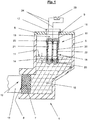
- FIG. 1 shows a storage container 5 for adhesive 10 with metering device 12 and sensor 15 for monitoring a level level 11.
- the storage container 5 in this case has a storage volume, which ends at its lower side of the housing in an applicator 1.
- the adhesive 10 in this case wets the rear area of a roller 7 of a metering device 12, wherein the side facing away from the adhesive 10 of the roller 7, the outlet opening 8 to the workpiece 13.
- the container 5 is closed by a lid 6.
- this At a suitable position of the lid 6, this has an opening 9, through which a sensor 15 is inserted into the container 5.
- the senor 15 protrudes into the adhesive level 11 of the adhesive 10, for example, with an immersion depth 14, wherein the sensor area dipping into the adhesive level 11 consists of a tubular housing 18. At its lid 6 facing the end of the sensor 15, this is formed with a housing 16 which projects through the opening 9 and can be limited by a stop 17 in its Einragianae into the container 5.
- the arranged within the tubular housing 18 electrodes 20, 21 are connected via electrical lines 24 to a controller 25 or control 25. With this control 25 or control 25, the adhesive level 11 is determined and evaluated.
- the sensor 15 protruding into the container 5 is positioned at a distance from the adhesive level 11 with its end of the tubular housing 18, so that no wetting of the sensor 15 with the adhesive 10 is produced.
- FIG. 2 From the FIG. 2 the structure of the sensor 15 in the immersed state within the adhesive 10 is shown.
- the electric field 23 changes according to the immersion depth of the sensor 15, wherein the tubular housing 18 of the sensor 15 is formed in the immersion region as a closed pot shape. It is thus not possible that adhesive can penetrate into the sensor 15.
- a tubular electrode 21 is spaced from the tubular housing 18 by means of an insulator 22.
- the insulator 22 may have purely insulating, but also in addition the electric field 23 reinforcing properties.
- an electrode 20, preferably rod-shaped electrode to the electrode 21 is introduced spaced.
- the spacing is formed by an air gap 26, which can be filled in accordance with the adhesive 10 to be used with a reinforcing the electric field 23 material. In this case, however, this material acts as an insulator between the electrode 20 and the electrode 21.
- this is formed with a housing 16, wherein through the housing 16 electrical lines 24 are directed to the control / regulation 25.
- This upper portion of the housing 16 forms the head part 19, which is limited by a stop 17.
- the sensor 15 can be displaced in its position within the storage container 5. This displaceability is limited by the stop 17 with a maximum insertion depth of the sensor 15.
Landscapes
- Physics & Mathematics (AREA)
- Engineering & Computer Science (AREA)
- Power Engineering (AREA)
- General Physics & Mathematics (AREA)
- Electromagnetism (AREA)
- Thermal Sciences (AREA)
- Fluid Mechanics (AREA)
- Coating Apparatus (AREA)
- Automation & Control Theory (AREA)
- Application Of Or Painting With Fluid Materials (AREA)
- Measurement Of Levels Of Liquids Or Fluent Solid Materials (AREA)
Applications Claiming Priority (1)
| Application Number | Priority Date | Filing Date | Title |
|---|---|---|---|
| DE102011014888A DE102011014888A1 (de) | 2011-03-23 | 2011-03-23 | Vorrichtung und Verfahren zur Steuerung/Regelung eines Füllstandsniveaus |
Publications (3)
| Publication Number | Publication Date |
|---|---|
| EP2503425A2 true EP2503425A2 (fr) | 2012-09-26 |
| EP2503425A3 EP2503425A3 (fr) | 2016-10-19 |
| EP2503425B1 EP2503425B1 (fr) | 2020-10-28 |
Family
ID=45841309
Family Applications (1)
| Application Number | Title | Priority Date | Filing Date |
|---|---|---|---|
| EP12158787.7A Active EP2503425B1 (fr) | 2011-03-23 | 2012-03-09 | Dispositif et procédé de commande/réglage d'un niveau de remplissage |
Country Status (3)
| Country | Link |
|---|---|
| EP (1) | EP2503425B1 (fr) |
| DE (1) | DE102011014888A1 (fr) |
| ES (1) | ES2838155T3 (fr) |
Cited By (1)
| Publication number | Priority date | Publication date | Assignee | Title |
|---|---|---|---|---|
| WO2021152406A1 (fr) * | 2020-01-28 | 2021-08-05 | Contiweb B.V. | Dispositif de revêtement |
Families Citing this family (2)
| Publication number | Priority date | Publication date | Assignee | Title |
|---|---|---|---|---|
| DE102017111013A1 (de) * | 2017-05-19 | 2018-11-22 | Holz-Her Gmbh | Kleberauftragsvorrichtung |
| DE102023108702A1 (de) | 2023-04-05 | 2024-10-10 | Homag Gmbh | Verfahren zum Betrieb einer Haftmittelauftragsvorrichtung sowie Beschichtungsmaschine |
Family Cites Families (9)
| Publication number | Priority date | Publication date | Assignee | Title |
|---|---|---|---|---|
| US3545650A (en) * | 1968-10-30 | 1970-12-08 | Honeywell Inc | Capacitive liquid quantity indicating and shut-off system |
| DE2652133A1 (de) * | 1976-11-16 | 1978-05-18 | Bielomatik Leuze & Co | Vorrichtung zum auftragen von leim |
| US4182363A (en) * | 1976-11-29 | 1980-01-08 | Fuller Mark W | Liquid level controller |
| DD144382A1 (de) * | 1979-08-13 | 1980-10-15 | Gerald Winker | Fuellstandsregeleinrichtung an beleimungsvorrichtungen fuer blockruecken und dergleichen |
| SE8003833L (sv) * | 1980-05-22 | 1981-11-23 | Woodtechnique Ab | Anordning for kontinuerlig blandning av flerkomponentlim |
| DE3029352C2 (de) * | 1980-08-01 | 1982-12-23 | Endress U. Hauser Gmbh U. Co, 7867 Maulburg | Kapazitive Füllstandsmeßanordnung mit einer stabförmigen Sonde für die Messung des Füllstandes in einem Behälter |
| DE8907208U1 (de) * | 1989-01-11 | 1989-07-27 | ELWE-Lehrsysteme GmbH, 3302 Cremlingen | Lehrgerät für die Regelungstechnik |
| FR2795817B1 (fr) * | 1999-07-02 | 2001-08-10 | Inst Francais Du Petrole | Sonde capacitive de mesure du niveau d'un liquide conducteur de l'electricite dans un recipient et procede de fabrication d'une telle sonde |
| JP5239357B2 (ja) * | 2008-01-28 | 2013-07-17 | パナソニック株式会社 | ペースト塗布装置 |
-
2011
- 2011-03-23 DE DE102011014888A patent/DE102011014888A1/de active Pending
-
2012
- 2012-03-09 EP EP12158787.7A patent/EP2503425B1/fr active Active
- 2012-03-09 ES ES12158787T patent/ES2838155T3/es active Active
Non-Patent Citations (1)
| Title |
|---|
| None |
Cited By (3)
| Publication number | Priority date | Publication date | Assignee | Title |
|---|---|---|---|---|
| WO2021152406A1 (fr) * | 2020-01-28 | 2021-08-05 | Contiweb B.V. | Dispositif de revêtement |
| NL2024775B1 (nl) * | 2020-01-28 | 2021-09-09 | Contiweb B V | Opbrenginrichting |
| US11896994B2 (en) | 2020-01-28 | 2024-02-13 | Contiweb B.V. | Coating device |
Also Published As
| Publication number | Publication date |
|---|---|
| EP2503425B1 (fr) | 2020-10-28 |
| DE102011014888A1 (de) | 2012-09-27 |
| EP2503425A3 (fr) | 2016-10-19 |
| ES2838155T3 (es) | 2021-07-01 |
Similar Documents
| Publication | Publication Date | Title |
|---|---|---|
| EP3329233B1 (fr) | Procédé et dispositif d'étalonnage sur site d'un thermomètre | |
| EP3452835B1 (fr) | Pointe de pipette pour dispositif de pipetage automatique | |
| WO2018015419A1 (fr) | Pointe de pipette pour dispositif de pipetage automatique et procédé pour la réaliser | |
| DE19841770A1 (de) | Vorrichtung und Verfahren zur Füllstandsmessung | |
| DE10004941A1 (de) | Temperierter Probennehmer für Flüssigkeiten | |
| EP2169392B1 (fr) | Procédé et dispositif destinés à la mesure de la dureté de l'eau | |
| EP1972905A2 (fr) | Dispositif de mesure du niveau de remplissage | |
| CH712764A2 (de) | Pipettenspitze aufweisend eine Volumenmesselektrode sowie Verfahren zu deren Herstellung und Pipettiervorrichtung. | |
| WO2017182491A1 (fr) | Dispositif de détermination de température et procédé d'étalonnage de celui-ci et de détermination de la témperature d'un milieu | |
| DE2658215A1 (de) | Vorrichtung zur messung der eigenschaft bzw. qualitaet einer fluessigkeit | |
| EP2647988B1 (fr) | Procédé et dispositif de mesure de la teneur en oxygène ou de la pression partielle d'oxygène dans un gaz de mesure | |
| EP2503425B1 (fr) | Dispositif et procédé de commande/réglage d'un niveau de remplissage | |
| CH670160A5 (fr) | ||
| EP3350557B1 (fr) | Procédé d'étalonnage d'un capteur de température présent dans un processus de la technique d'automatisation | |
| EP3570017A2 (fr) | Préparation d'une mesure de distillation | |
| EP0236693B1 (fr) | Dispositif de contrôle d'un produit fluide transporté dans un tube | |
| WO2008151804A1 (fr) | Dispositif de dosage | |
| EP1067368A1 (fr) | Dispositif de mesure du niveau | |
| EP1992921A1 (fr) | Procédé et dispositif destiné à la détection de l'état de remplissage | |
| EP2707680B1 (fr) | Procede d'ajustement de la quantite d'un liquide a doser dans un embout d'une pipette par detection de vibrations et dispositif pour executer le procede | |
| EP3390976B1 (fr) | Procédé de détermination d'un débit ou d'une vitesse d'écoulement d'un milieu | |
| DE112016007164T5 (de) | Antriebsschraubenvorrichtung, Flüssigkeitsfördermechanismus und Flüssigkeitsförderverfahren | |
| WO2018028966A1 (fr) | Capteur pour débitmètre thermique, débitmètre thermique et procédé de fabrication d'un capteur d'un débitmètre thermique | |
| DE1295867B (de) | Verfahren und Vorrichtung zur Abtastung von Fuellstaenden in Fluessigkeitsbehaeltern | |
| DE102008015052A1 (de) | Stabförmige kapazitive Füllstandsmesssonde |
Legal Events
| Date | Code | Title | Description |
|---|---|---|---|
| PUAI | Public reference made under article 153(3) epc to a published international application that has entered the european phase |
Free format text: ORIGINAL CODE: 0009012 |
|
| AK | Designated contracting states |
Kind code of ref document: A2 Designated state(s): AL AT BE BG CH CY CZ DE DK EE ES FI FR GB GR HR HU IE IS IT LI LT LU LV MC MK MT NL NO PL PT RO RS SE SI SK SM TR |
|
| AX | Request for extension of the european patent |
Extension state: BA ME |
|
| PUAL | Search report despatched |
Free format text: ORIGINAL CODE: 0009013 |
|
| RAP1 | Party data changed (applicant data changed or rights of an application transferred) |
Owner name: HOMAG GMBH |
|
| AK | Designated contracting states |
Kind code of ref document: A3 Designated state(s): AL AT BE BG CH CY CZ DE DK EE ES FI FR GB GR HR HU IE IS IT LI LT LU LV MC MK MT NL NO PL PT RO RS SE SI SK SM TR |
|
| AX | Request for extension of the european patent |
Extension state: BA ME |
|
| RIC1 | Information provided on ipc code assigned before grant |
Ipc: G05D 9/12 20060101AFI20160912BHEP Ipc: B05C 11/10 20060101ALI20160912BHEP Ipc: G01F 23/26 20060101ALI20160912BHEP Ipc: F16B 11/00 20060101ALI20160912BHEP |
|
| STAA | Information on the status of an ep patent application or granted ep patent |
Free format text: STATUS: REQUEST FOR EXAMINATION WAS MADE |
|
| 17P | Request for examination filed |
Effective date: 20170411 |
|
| RBV | Designated contracting states (corrected) |
Designated state(s): AL AT BE BG CH CY CZ DE DK EE ES FI FR GB GR HR HU IE IS IT LI LT LU LV MC MK MT NL NO PL PT RO RS SE SI SK SM TR |
|
| STAA | Information on the status of an ep patent application or granted ep patent |
Free format text: STATUS: EXAMINATION IS IN PROGRESS |
|
| 17Q | First examination report despatched |
Effective date: 20180219 |
|
| GRAP | Despatch of communication of intention to grant a patent |
Free format text: ORIGINAL CODE: EPIDOSNIGR1 |
|
| STAA | Information on the status of an ep patent application or granted ep patent |
Free format text: STATUS: GRANT OF PATENT IS INTENDED |
|
| INTG | Intention to grant announced |
Effective date: 20200519 |
|
| GRAS | Grant fee paid |
Free format text: ORIGINAL CODE: EPIDOSNIGR3 |
|
| GRAA | (expected) grant |
Free format text: ORIGINAL CODE: 0009210 |
|
| STAA | Information on the status of an ep patent application or granted ep patent |
Free format text: STATUS: THE PATENT HAS BEEN GRANTED |
|
| AK | Designated contracting states |
Kind code of ref document: B1 Designated state(s): AL AT BE BG CH CY CZ DE DK EE ES FI FR GB GR HR HU IE IS IT LI LT LU LV MC MK MT NL NO PL PT RO RS SE SI SK SM TR |
|
| REG | Reference to a national code |
Ref country code: GB Ref legal event code: FG4D Free format text: NOT ENGLISH |
|
| REG | Reference to a national code |
Ref country code: CH Ref legal event code: EP |
|
| REG | Reference to a national code |
Ref country code: AT Ref legal event code: REF Ref document number: 1328853 Country of ref document: AT Kind code of ref document: T Effective date: 20201115 |
|
| REG | Reference to a national code |
Ref country code: DE Ref legal event code: R096 Ref document number: 502012016438 Country of ref document: DE |
|
| REG | Reference to a national code |
Ref country code: IE Ref legal event code: FG4D Free format text: LANGUAGE OF EP DOCUMENT: GERMAN |
|
| REG | Reference to a national code |
Ref country code: NL Ref legal event code: MP Effective date: 20201028 |
|
| PG25 | Lapsed in a contracting state [announced via postgrant information from national office to epo] |
Ref country code: NL Free format text: LAPSE BECAUSE OF FAILURE TO SUBMIT A TRANSLATION OF THE DESCRIPTION OR TO PAY THE FEE WITHIN THE PRESCRIBED TIME-LIMIT Effective date: 20201028 Ref country code: NO Free format text: LAPSE BECAUSE OF FAILURE TO SUBMIT A TRANSLATION OF THE DESCRIPTION OR TO PAY THE FEE WITHIN THE PRESCRIBED TIME-LIMIT Effective date: 20210128 Ref country code: PT Free format text: LAPSE BECAUSE OF FAILURE TO SUBMIT A TRANSLATION OF THE DESCRIPTION OR TO PAY THE FEE WITHIN THE PRESCRIBED TIME-LIMIT Effective date: 20210301 Ref country code: RS Free format text: LAPSE BECAUSE OF FAILURE TO SUBMIT A TRANSLATION OF THE DESCRIPTION OR TO PAY THE FEE WITHIN THE PRESCRIBED TIME-LIMIT Effective date: 20201028 Ref country code: FI Free format text: LAPSE BECAUSE OF FAILURE TO SUBMIT A TRANSLATION OF THE DESCRIPTION OR TO PAY THE FEE WITHIN THE PRESCRIBED TIME-LIMIT Effective date: 20201028 Ref country code: GR Free format text: LAPSE BECAUSE OF FAILURE TO SUBMIT A TRANSLATION OF THE DESCRIPTION OR TO PAY THE FEE WITHIN THE PRESCRIBED TIME-LIMIT Effective date: 20210129 |
|
| REG | Reference to a national code |
Ref country code: LT Ref legal event code: MG4D |
|
| PG25 | Lapsed in a contracting state [announced via postgrant information from national office to epo] |
Ref country code: BG Free format text: LAPSE BECAUSE OF FAILURE TO SUBMIT A TRANSLATION OF THE DESCRIPTION OR TO PAY THE FEE WITHIN THE PRESCRIBED TIME-LIMIT Effective date: 20210128 Ref country code: IS Free format text: LAPSE BECAUSE OF FAILURE TO SUBMIT A TRANSLATION OF THE DESCRIPTION OR TO PAY THE FEE WITHIN THE PRESCRIBED TIME-LIMIT Effective date: 20210228 Ref country code: PL Free format text: LAPSE BECAUSE OF FAILURE TO SUBMIT A TRANSLATION OF THE DESCRIPTION OR TO PAY THE FEE WITHIN THE PRESCRIBED TIME-LIMIT Effective date: 20201028 Ref country code: SE Free format text: LAPSE BECAUSE OF FAILURE TO SUBMIT A TRANSLATION OF THE DESCRIPTION OR TO PAY THE FEE WITHIN THE PRESCRIBED TIME-LIMIT Effective date: 20201028 Ref country code: LV Free format text: LAPSE BECAUSE OF FAILURE TO SUBMIT A TRANSLATION OF THE DESCRIPTION OR TO PAY THE FEE WITHIN THE PRESCRIBED TIME-LIMIT Effective date: 20201028 |
|
| PG25 | Lapsed in a contracting state [announced via postgrant information from national office to epo] |
Ref country code: HR Free format text: LAPSE BECAUSE OF FAILURE TO SUBMIT A TRANSLATION OF THE DESCRIPTION OR TO PAY THE FEE WITHIN THE PRESCRIBED TIME-LIMIT Effective date: 20201028 |
|
| REG | Reference to a national code |
Ref country code: DE Ref legal event code: R097 Ref document number: 502012016438 Country of ref document: DE |
|
| PG25 | Lapsed in a contracting state [announced via postgrant information from national office to epo] |
Ref country code: EE Free format text: LAPSE BECAUSE OF FAILURE TO SUBMIT A TRANSLATION OF THE DESCRIPTION OR TO PAY THE FEE WITHIN THE PRESCRIBED TIME-LIMIT Effective date: 20201028 Ref country code: CZ Free format text: LAPSE BECAUSE OF FAILURE TO SUBMIT A TRANSLATION OF THE DESCRIPTION OR TO PAY THE FEE WITHIN THE PRESCRIBED TIME-LIMIT Effective date: 20201028 Ref country code: SM Free format text: LAPSE BECAUSE OF FAILURE TO SUBMIT A TRANSLATION OF THE DESCRIPTION OR TO PAY THE FEE WITHIN THE PRESCRIBED TIME-LIMIT Effective date: 20201028 Ref country code: SK Free format text: LAPSE BECAUSE OF FAILURE TO SUBMIT A TRANSLATION OF THE DESCRIPTION OR TO PAY THE FEE WITHIN THE PRESCRIBED TIME-LIMIT Effective date: 20201028 Ref country code: RO Free format text: LAPSE BECAUSE OF FAILURE TO SUBMIT A TRANSLATION OF THE DESCRIPTION OR TO PAY THE FEE WITHIN THE PRESCRIBED TIME-LIMIT Effective date: 20201028 Ref country code: LT Free format text: LAPSE BECAUSE OF FAILURE TO SUBMIT A TRANSLATION OF THE DESCRIPTION OR TO PAY THE FEE WITHIN THE PRESCRIBED TIME-LIMIT Effective date: 20201028 |
|
| PG25 | Lapsed in a contracting state [announced via postgrant information from national office to epo] |
Ref country code: DK Free format text: LAPSE BECAUSE OF FAILURE TO SUBMIT A TRANSLATION OF THE DESCRIPTION OR TO PAY THE FEE WITHIN THE PRESCRIBED TIME-LIMIT Effective date: 20201028 |
|
| PLBE | No opposition filed within time limit |
Free format text: ORIGINAL CODE: 0009261 |
|
| STAA | Information on the status of an ep patent application or granted ep patent |
Free format text: STATUS: NO OPPOSITION FILED WITHIN TIME LIMIT |
|
| 26N | No opposition filed |
Effective date: 20210729 |
|
| PG25 | Lapsed in a contracting state [announced via postgrant information from national office to epo] |
Ref country code: AL Free format text: LAPSE BECAUSE OF FAILURE TO SUBMIT A TRANSLATION OF THE DESCRIPTION OR TO PAY THE FEE WITHIN THE PRESCRIBED TIME-LIMIT Effective date: 20201028 Ref country code: MC Free format text: LAPSE BECAUSE OF FAILURE TO SUBMIT A TRANSLATION OF THE DESCRIPTION OR TO PAY THE FEE WITHIN THE PRESCRIBED TIME-LIMIT Effective date: 20201028 |
|
| REG | Reference to a national code |
Ref country code: CH Ref legal event code: PL |
|
| GBPC | Gb: european patent ceased through non-payment of renewal fee |
Effective date: 20210309 |
|
| PG25 | Lapsed in a contracting state [announced via postgrant information from national office to epo] |
Ref country code: SI Free format text: LAPSE BECAUSE OF FAILURE TO SUBMIT A TRANSLATION OF THE DESCRIPTION OR TO PAY THE FEE WITHIN THE PRESCRIBED TIME-LIMIT Effective date: 20201028 |
|
| REG | Reference to a national code |
Ref country code: BE Ref legal event code: MM Effective date: 20210331 |
|
| PG25 | Lapsed in a contracting state [announced via postgrant information from national office to epo] |
Ref country code: GB Free format text: LAPSE BECAUSE OF NON-PAYMENT OF DUE FEES Effective date: 20210309 Ref country code: FR Free format text: LAPSE BECAUSE OF NON-PAYMENT OF DUE FEES Effective date: 20210331 Ref country code: IE Free format text: LAPSE BECAUSE OF NON-PAYMENT OF DUE FEES Effective date: 20210309 Ref country code: LU Free format text: LAPSE BECAUSE OF NON-PAYMENT OF DUE FEES Effective date: 20210309 Ref country code: LI Free format text: LAPSE BECAUSE OF NON-PAYMENT OF DUE FEES Effective date: 20210331 Ref country code: CH Free format text: LAPSE BECAUSE OF NON-PAYMENT OF DUE FEES Effective date: 20210331 |
|
| PG25 | Lapsed in a contracting state [announced via postgrant information from national office to epo] |
Ref country code: IS Free format text: LAPSE BECAUSE OF FAILURE TO SUBMIT A TRANSLATION OF THE DESCRIPTION OR TO PAY THE FEE WITHIN THE PRESCRIBED TIME-LIMIT Effective date: 20210228 |
|
| PG25 | Lapsed in a contracting state [announced via postgrant information from national office to epo] |
Ref country code: BE Free format text: LAPSE BECAUSE OF NON-PAYMENT OF DUE FEES Effective date: 20210331 |
|
| PGFP | Annual fee paid to national office [announced via postgrant information from national office to epo] |
Ref country code: ES Payment date: 20220405 Year of fee payment: 11 |
|
| PG25 | Lapsed in a contracting state [announced via postgrant information from national office to epo] |
Ref country code: HU Free format text: LAPSE BECAUSE OF FAILURE TO SUBMIT A TRANSLATION OF THE DESCRIPTION OR TO PAY THE FEE WITHIN THE PRESCRIBED TIME-LIMIT; INVALID AB INITIO Effective date: 20120309 Ref country code: CY Free format text: LAPSE BECAUSE OF FAILURE TO SUBMIT A TRANSLATION OF THE DESCRIPTION OR TO PAY THE FEE WITHIN THE PRESCRIBED TIME-LIMIT Effective date: 20201028 |
|
| P01 | Opt-out of the competence of the unified patent court (upc) registered |
Effective date: 20230529 |
|
| PG25 | Lapsed in a contracting state [announced via postgrant information from national office to epo] |
Ref country code: MK Free format text: LAPSE BECAUSE OF FAILURE TO SUBMIT A TRANSLATION OF THE DESCRIPTION OR TO PAY THE FEE WITHIN THE PRESCRIBED TIME-LIMIT Effective date: 20201028 |
|
| REG | Reference to a national code |
Ref country code: ES Ref legal event code: FD2A Effective date: 20240503 |
|
| PG25 | Lapsed in a contracting state [announced via postgrant information from national office to epo] |
Ref country code: ES Free format text: LAPSE BECAUSE OF NON-PAYMENT OF DUE FEES Effective date: 20230310 |
|
| PG25 | Lapsed in a contracting state [announced via postgrant information from national office to epo] |
Ref country code: ES Free format text: LAPSE BECAUSE OF NON-PAYMENT OF DUE FEES Effective date: 20230310 |
|
| PG25 | Lapsed in a contracting state [announced via postgrant information from national office to epo] |
Ref country code: MT Free format text: LAPSE BECAUSE OF FAILURE TO SUBMIT A TRANSLATION OF THE DESCRIPTION OR TO PAY THE FEE WITHIN THE PRESCRIBED TIME-LIMIT Effective date: 20201028 |
|
| PG25 | Lapsed in a contracting state [announced via postgrant information from national office to epo] |
Ref country code: TR Free format text: LAPSE BECAUSE OF FAILURE TO SUBMIT A TRANSLATION OF THE DESCRIPTION OR TO PAY THE FEE WITHIN THE PRESCRIBED TIME-LIMIT Effective date: 20201028 |
|
| PGFP | Annual fee paid to national office [announced via postgrant information from national office to epo] |
Ref country code: DE Payment date: 20260323 Year of fee payment: 15 |
|
| PGFP | Annual fee paid to national office [announced via postgrant information from national office to epo] |
Ref country code: AT Payment date: 20260324 Year of fee payment: 15 |
|
| PGFP | Annual fee paid to national office [announced via postgrant information from national office to epo] |
Ref country code: IT Payment date: 20260325 Year of fee payment: 15 |