EP2504151B1 - Heisssiegelmaschine für die montage von textilartikeln und damit ausgeführtes verfahren - Google Patents
Heisssiegelmaschine für die montage von textilartikeln und damit ausgeführtes verfahren Download PDFInfo
- Publication number
- EP2504151B1 EP2504151B1 EP10816374.2A EP10816374A EP2504151B1 EP 2504151 B1 EP2504151 B1 EP 2504151B1 EP 10816374 A EP10816374 A EP 10816374A EP 2504151 B1 EP2504151 B1 EP 2504151B1
- Authority
- EP
- European Patent Office
- Prior art keywords
- conveying
- manufacture
- heat
- layers
- article
- Prior art date
- Legal status (The legal status is an assumption and is not a legal conclusion. Google has not performed a legal analysis and makes no representation as to the accuracy of the status listed.)
- Active
Links
- 238000004519 manufacturing process Methods 0.000 title claims description 57
- 239000004753 textile Substances 0.000 title claims description 23
- 238000007789 sealing Methods 0.000 title claims description 21
- 238000000034 method Methods 0.000 title claims description 10
- 238000010438 heat treatment Methods 0.000 claims description 28
- 230000004907 flux Effects 0.000 claims description 16
- 230000009471 action Effects 0.000 claims description 14
- 230000004913 activation Effects 0.000 claims description 10
- 238000011144 upstream manufacturing Methods 0.000 claims description 8
- 239000004020 conductor Substances 0.000 claims description 5
- 239000007769 metal material Substances 0.000 claims description 4
- 238000004891 communication Methods 0.000 claims description 2
- 230000008878 coupling Effects 0.000 claims description 2
- 238000010168 coupling process Methods 0.000 claims description 2
- 238000005859 coupling reaction Methods 0.000 claims description 2
- 239000010410 layer Substances 0.000 description 58
- 239000004744 fabric Substances 0.000 description 8
- 239000003795 chemical substances by application Substances 0.000 description 7
- 238000005304 joining Methods 0.000 description 7
- 239000000463 material Substances 0.000 description 5
- 230000006872 improvement Effects 0.000 description 3
- RYGMFSIKBFXOCR-UHFFFAOYSA-N Copper Chemical compound [Cu] RYGMFSIKBFXOCR-UHFFFAOYSA-N 0.000 description 2
- 230000004888 barrier function Effects 0.000 description 2
- 229910052802 copper Inorganic materials 0.000 description 2
- 239000010949 copper Substances 0.000 description 2
- 230000001934 delay Effects 0.000 description 2
- 239000012528 membrane Substances 0.000 description 2
- 239000004745 nonwoven fabric Substances 0.000 description 2
- 229920002635 polyurethane Polymers 0.000 description 2
- 239000004814 polyurethane Substances 0.000 description 2
- 238000003825 pressing Methods 0.000 description 2
- 239000000758 substrate Substances 0.000 description 2
- 239000000853 adhesive Substances 0.000 description 1
- 230000001070 adhesive effect Effects 0.000 description 1
- 239000012790 adhesive layer Substances 0.000 description 1
- 230000005540 biological transmission Effects 0.000 description 1
- 230000001419 dependent effect Effects 0.000 description 1
- 238000009792 diffusion process Methods 0.000 description 1
- 238000006073 displacement reaction Methods 0.000 description 1
- 230000008030 elimination Effects 0.000 description 1
- 238000003379 elimination reaction Methods 0.000 description 1
- 238000002844 melting Methods 0.000 description 1
- 230000008018 melting Effects 0.000 description 1
- 230000010355 oscillation Effects 0.000 description 1
- 230000000704 physical effect Effects 0.000 description 1
- 239000007787 solid Substances 0.000 description 1
- 229920002994 synthetic fiber Polymers 0.000 description 1
- 239000008207 working material Substances 0.000 description 1
Images


Classifications
-
- B—PERFORMING OPERATIONS; TRANSPORTING
- B29—WORKING OF PLASTICS; WORKING OF SUBSTANCES IN A PLASTIC STATE IN GENERAL
- B29C—SHAPING OR JOINING OF PLASTICS; SHAPING OF MATERIAL IN A PLASTIC STATE, NOT OTHERWISE PROVIDED FOR; AFTER-TREATMENT OF THE SHAPED PRODUCTS, e.g. REPAIRING
- B29C66/00—General aspects of processes or apparatus for joining preformed parts
- B29C66/80—General aspects of machine operations or constructions and parts thereof
- B29C66/83—General aspects of machine operations or constructions and parts thereof characterised by the movement of the joining or pressing tools
- B29C66/834—General aspects of machine operations or constructions and parts thereof characterised by the movement of the joining or pressing tools moving with the parts to be joined
- B29C66/8341—Roller, cylinder or drum types; Band or belt types; Ball types
- B29C66/83431—Roller, cylinder or drum types; Band or belt types; Ball types rollers, cylinders or drums cooperating with bands or belts
-
- B—PERFORMING OPERATIONS; TRANSPORTING
- B29—WORKING OF PLASTICS; WORKING OF SUBSTANCES IN A PLASTIC STATE IN GENERAL
- B29C—SHAPING OR JOINING OF PLASTICS; SHAPING OF MATERIAL IN A PLASTIC STATE, NOT OTHERWISE PROVIDED FOR; AFTER-TREATMENT OF THE SHAPED PRODUCTS, e.g. REPAIRING
- B29C65/00—Joining or sealing of preformed parts, e.g. welding of plastics materials; Apparatus therefor
- B29C65/02—Joining or sealing of preformed parts, e.g. welding of plastics materials; Apparatus therefor by heating, with or without pressure
- B29C65/10—Joining or sealing of preformed parts, e.g. welding of plastics materials; Apparatus therefor by heating, with or without pressure using hot gases (e.g. combustion gases) or flames coming in contact with at least one of the parts to be joined
-
- B—PERFORMING OPERATIONS; TRANSPORTING
- B29—WORKING OF PLASTICS; WORKING OF SUBSTANCES IN A PLASTIC STATE IN GENERAL
- B29C—SHAPING OR JOINING OF PLASTICS; SHAPING OF MATERIAL IN A PLASTIC STATE, NOT OTHERWISE PROVIDED FOR; AFTER-TREATMENT OF THE SHAPED PRODUCTS, e.g. REPAIRING
- B29C65/00—Joining or sealing of preformed parts, e.g. welding of plastics materials; Apparatus therefor
- B29C65/02—Joining or sealing of preformed parts, e.g. welding of plastics materials; Apparatus therefor by heating, with or without pressure
- B29C65/18—Joining or sealing of preformed parts, e.g. welding of plastics materials; Apparatus therefor by heating, with or without pressure using heated tools
-
- B—PERFORMING OPERATIONS; TRANSPORTING
- B29—WORKING OF PLASTICS; WORKING OF SUBSTANCES IN A PLASTIC STATE IN GENERAL
- B29C—SHAPING OR JOINING OF PLASTICS; SHAPING OF MATERIAL IN A PLASTIC STATE, NOT OTHERWISE PROVIDED FOR; AFTER-TREATMENT OF THE SHAPED PRODUCTS, e.g. REPAIRING
- B29C65/00—Joining or sealing of preformed parts, e.g. welding of plastics materials; Apparatus therefor
- B29C65/02—Joining or sealing of preformed parts, e.g. welding of plastics materials; Apparatus therefor by heating, with or without pressure
- B29C65/18—Joining or sealing of preformed parts, e.g. welding of plastics materials; Apparatus therefor by heating, with or without pressure using heated tools
- B29C65/24—Joining or sealing of preformed parts, e.g. welding of plastics materials; Apparatus therefor by heating, with or without pressure using heated tools characterised by the means for heating the tool
- B29C65/26—Hot fluid
-
- B—PERFORMING OPERATIONS; TRANSPORTING
- B29—WORKING OF PLASTICS; WORKING OF SUBSTANCES IN A PLASTIC STATE IN GENERAL
- B29C—SHAPING OR JOINING OF PLASTICS; SHAPING OF MATERIAL IN A PLASTIC STATE, NOT OTHERWISE PROVIDED FOR; AFTER-TREATMENT OF THE SHAPED PRODUCTS, e.g. REPAIRING
- B29C65/00—Joining or sealing of preformed parts, e.g. welding of plastics materials; Apparatus therefor
- B29C65/48—Joining or sealing of preformed parts, e.g. welding of plastics materials; Apparatus therefor using adhesives, i.e. using supplementary joining material; solvent bonding
- B29C65/4805—Joining or sealing of preformed parts, e.g. welding of plastics materials; Apparatus therefor using adhesives, i.e. using supplementary joining material; solvent bonding characterised by the type of adhesives
- B29C65/481—Non-reactive adhesives, e.g. physically hardening adhesives
- B29C65/4815—Hot melt adhesives, e.g. thermoplastic adhesives
-
- B—PERFORMING OPERATIONS; TRANSPORTING
- B29—WORKING OF PLASTICS; WORKING OF SUBSTANCES IN A PLASTIC STATE IN GENERAL
- B29C—SHAPING OR JOINING OF PLASTICS; SHAPING OF MATERIAL IN A PLASTIC STATE, NOT OTHERWISE PROVIDED FOR; AFTER-TREATMENT OF THE SHAPED PRODUCTS, e.g. REPAIRING
- B29C65/00—Joining or sealing of preformed parts, e.g. welding of plastics materials; Apparatus therefor
- B29C65/48—Joining or sealing of preformed parts, e.g. welding of plastics materials; Apparatus therefor using adhesives, i.e. using supplementary joining material; solvent bonding
- B29C65/50—Joining or sealing of preformed parts, e.g. welding of plastics materials; Apparatus therefor using adhesives, i.e. using supplementary joining material; solvent bonding using adhesive tape, e.g. thermoplastic tape; using threads or the like
- B29C65/5057—Joining or sealing of preformed parts, e.g. welding of plastics materials; Apparatus therefor using adhesives, i.e. using supplementary joining material; solvent bonding using adhesive tape, e.g. thermoplastic tape; using threads or the like positioned between the surfaces to be joined
-
- B—PERFORMING OPERATIONS; TRANSPORTING
- B29—WORKING OF PLASTICS; WORKING OF SUBSTANCES IN A PLASTIC STATE IN GENERAL
- B29C—SHAPING OR JOINING OF PLASTICS; SHAPING OF MATERIAL IN A PLASTIC STATE, NOT OTHERWISE PROVIDED FOR; AFTER-TREATMENT OF THE SHAPED PRODUCTS, e.g. REPAIRING
- B29C65/00—Joining or sealing of preformed parts, e.g. welding of plastics materials; Apparatus therefor
- B29C65/72—Joining or sealing of preformed parts, e.g. welding of plastics materials; Apparatus therefor by combined operations or combined techniques, e.g. welding and stitching
-
- B—PERFORMING OPERATIONS; TRANSPORTING
- B29—WORKING OF PLASTICS; WORKING OF SUBSTANCES IN A PLASTIC STATE IN GENERAL
- B29C—SHAPING OR JOINING OF PLASTICS; SHAPING OF MATERIAL IN A PLASTIC STATE, NOT OTHERWISE PROVIDED FOR; AFTER-TREATMENT OF THE SHAPED PRODUCTS, e.g. REPAIRING
- B29C66/00—General aspects of processes or apparatus for joining preformed parts
- B29C66/40—General aspects of joining substantially flat articles, e.g. plates, sheets or web-like materials; Making flat seams in tubular or hollow articles; Joining single elements to substantially flat surfaces
- B29C66/41—Joining substantially flat articles ; Making flat seams in tubular or hollow articles
- B29C66/43—Joining a relatively small portion of the surface of said articles
-
- B—PERFORMING OPERATIONS; TRANSPORTING
- B29—WORKING OF PLASTICS; WORKING OF SUBSTANCES IN A PLASTIC STATE IN GENERAL
- B29C—SHAPING OR JOINING OF PLASTICS; SHAPING OF MATERIAL IN A PLASTIC STATE, NOT OTHERWISE PROVIDED FOR; AFTER-TREATMENT OF THE SHAPED PRODUCTS, e.g. REPAIRING
- B29C66/00—General aspects of processes or apparatus for joining preformed parts
- B29C66/40—General aspects of joining substantially flat articles, e.g. plates, sheets or web-like materials; Making flat seams in tubular or hollow articles; Joining single elements to substantially flat surfaces
- B29C66/41—Joining substantially flat articles ; Making flat seams in tubular or hollow articles
- B29C66/43—Joining a relatively small portion of the surface of said articles
- B29C66/431—Joining the articles to themselves
-
- B—PERFORMING OPERATIONS; TRANSPORTING
- B29—WORKING OF PLASTICS; WORKING OF SUBSTANCES IN A PLASTIC STATE IN GENERAL
- B29C—SHAPING OR JOINING OF PLASTICS; SHAPING OF MATERIAL IN A PLASTIC STATE, NOT OTHERWISE PROVIDED FOR; AFTER-TREATMENT OF THE SHAPED PRODUCTS, e.g. REPAIRING
- B29C66/00—General aspects of processes or apparatus for joining preformed parts
- B29C66/70—General aspects of processes or apparatus for joining preformed parts characterised by the composition, physical properties or the structure of the material of the parts to be joined; Joining with non-plastics material
- B29C66/72—General aspects of processes or apparatus for joining preformed parts characterised by the composition, physical properties or the structure of the material of the parts to be joined; Joining with non-plastics material characterised by the structure of the material of the parts to be joined
- B29C66/729—Textile or other fibrous material made from plastics
-
- B—PERFORMING OPERATIONS; TRANSPORTING
- B29—WORKING OF PLASTICS; WORKING OF SUBSTANCES IN A PLASTIC STATE IN GENERAL
- B29C—SHAPING OR JOINING OF PLASTICS; SHAPING OF MATERIAL IN A PLASTIC STATE, NOT OTHERWISE PROVIDED FOR; AFTER-TREATMENT OF THE SHAPED PRODUCTS, e.g. REPAIRING
- B29C66/00—General aspects of processes or apparatus for joining preformed parts
- B29C66/80—General aspects of machine operations or constructions and parts thereof
- B29C66/81—General aspects of the pressing elements, i.e. the elements applying pressure on the parts to be joined in the area to be joined, e.g. the welding jaws or clamps
- B29C66/812—General aspects of the pressing elements, i.e. the elements applying pressure on the parts to be joined in the area to be joined, e.g. the welding jaws or clamps characterised by the composition, by the structure, by the intensive physical properties or by the optical properties of the material constituting the pressing elements, e.g. constituting the welding jaws or clamps
- B29C66/8126—General aspects of the pressing elements, i.e. the elements applying pressure on the parts to be joined in the area to be joined, e.g. the welding jaws or clamps characterised by the composition, by the structure, by the intensive physical properties or by the optical properties of the material constituting the pressing elements, e.g. constituting the welding jaws or clamps characterised by the intensive physical properties or by the optical properties of the material constituting the pressing elements, e.g. constituting the welding jaws or clamps
- B29C66/81261—Thermal properties, e.g. thermal conductivity, thermal expansion coefficient
-
- B—PERFORMING OPERATIONS; TRANSPORTING
- B29—WORKING OF PLASTICS; WORKING OF SUBSTANCES IN A PLASTIC STATE IN GENERAL
- B29C—SHAPING OR JOINING OF PLASTICS; SHAPING OF MATERIAL IN A PLASTIC STATE, NOT OTHERWISE PROVIDED FOR; AFTER-TREATMENT OF THE SHAPED PRODUCTS, e.g. REPAIRING
- B29C66/00—General aspects of processes or apparatus for joining preformed parts
- B29C66/80—General aspects of machine operations or constructions and parts thereof
- B29C66/84—Specific machine types or machines suitable for specific applications
- B29C66/845—C-clamp type or sewing machine type
-
- B—PERFORMING OPERATIONS; TRANSPORTING
- B29—WORKING OF PLASTICS; WORKING OF SUBSTANCES IN A PLASTIC STATE IN GENERAL
- B29C—SHAPING OR JOINING OF PLASTICS; SHAPING OF MATERIAL IN A PLASTIC STATE, NOT OTHERWISE PROVIDED FOR; AFTER-TREATMENT OF THE SHAPED PRODUCTS, e.g. REPAIRING
- B29C65/00—Joining or sealing of preformed parts, e.g. welding of plastics materials; Apparatus therefor
- B29C65/02—Joining or sealing of preformed parts, e.g. welding of plastics materials; Apparatus therefor by heating, with or without pressure
- B29C65/10—Joining or sealing of preformed parts, e.g. welding of plastics materials; Apparatus therefor by heating, with or without pressure using hot gases (e.g. combustion gases) or flames coming in contact with at least one of the parts to be joined
- B29C65/103—Joining or sealing of preformed parts, e.g. welding of plastics materials; Apparatus therefor by heating, with or without pressure using hot gases (e.g. combustion gases) or flames coming in contact with at least one of the parts to be joined direct heating both surfaces to be joined
-
- B—PERFORMING OPERATIONS; TRANSPORTING
- B29—WORKING OF PLASTICS; WORKING OF SUBSTANCES IN A PLASTIC STATE IN GENERAL
- B29C—SHAPING OR JOINING OF PLASTICS; SHAPING OF MATERIAL IN A PLASTIC STATE, NOT OTHERWISE PROVIDED FOR; AFTER-TREATMENT OF THE SHAPED PRODUCTS, e.g. REPAIRING
- B29C65/00—Joining or sealing of preformed parts, e.g. welding of plastics materials; Apparatus therefor
- B29C65/48—Joining or sealing of preformed parts, e.g. welding of plastics materials; Apparatus therefor using adhesives, i.e. using supplementary joining material; solvent bonding
- B29C65/50—Joining or sealing of preformed parts, e.g. welding of plastics materials; Apparatus therefor using adhesives, i.e. using supplementary joining material; solvent bonding using adhesive tape, e.g. thermoplastic tape; using threads or the like
- B29C65/5007—Joining or sealing of preformed parts, e.g. welding of plastics materials; Apparatus therefor using adhesives, i.e. using supplementary joining material; solvent bonding using adhesive tape, e.g. thermoplastic tape; using threads or the like characterised by the structure of said adhesive tape, threads or the like
- B29C65/5021—Joining or sealing of preformed parts, e.g. welding of plastics materials; Apparatus therefor using adhesives, i.e. using supplementary joining material; solvent bonding using adhesive tape, e.g. thermoplastic tape; using threads or the like characterised by the structure of said adhesive tape, threads or the like being multi-layered
-
- B—PERFORMING OPERATIONS; TRANSPORTING
- B29—WORKING OF PLASTICS; WORKING OF SUBSTANCES IN A PLASTIC STATE IN GENERAL
- B29C—SHAPING OR JOINING OF PLASTICS; SHAPING OF MATERIAL IN A PLASTIC STATE, NOT OTHERWISE PROVIDED FOR; AFTER-TREATMENT OF THE SHAPED PRODUCTS, e.g. REPAIRING
- B29C65/00—Joining or sealing of preformed parts, e.g. welding of plastics materials; Apparatus therefor
- B29C65/48—Joining or sealing of preformed parts, e.g. welding of plastics materials; Apparatus therefor using adhesives, i.e. using supplementary joining material; solvent bonding
- B29C65/50—Joining or sealing of preformed parts, e.g. welding of plastics materials; Apparatus therefor using adhesives, i.e. using supplementary joining material; solvent bonding using adhesive tape, e.g. thermoplastic tape; using threads or the like
- B29C65/5092—Joining or sealing of preformed parts, e.g. welding of plastics materials; Apparatus therefor using adhesives, i.e. using supplementary joining material; solvent bonding using adhesive tape, e.g. thermoplastic tape; using threads or the like characterised by the tape handling mechanisms, e.g. using vacuum
-
- B—PERFORMING OPERATIONS; TRANSPORTING
- B29—WORKING OF PLASTICS; WORKING OF SUBSTANCES IN A PLASTIC STATE IN GENERAL
- B29C—SHAPING OR JOINING OF PLASTICS; SHAPING OF MATERIAL IN A PLASTIC STATE, NOT OTHERWISE PROVIDED FOR; AFTER-TREATMENT OF THE SHAPED PRODUCTS, e.g. REPAIRING
- B29C66/00—General aspects of processes or apparatus for joining preformed parts
- B29C66/01—General aspects dealing with the joint area or with the area to be joined
- B29C66/02—Preparation of the material, in the area to be joined, prior to joining or welding
- B29C66/024—Thermal pre-treatments
- B29C66/0242—Heating, or preheating, e.g. drying
-
- B—PERFORMING OPERATIONS; TRANSPORTING
- B29—WORKING OF PLASTICS; WORKING OF SUBSTANCES IN A PLASTIC STATE IN GENERAL
- B29C—SHAPING OR JOINING OF PLASTICS; SHAPING OF MATERIAL IN A PLASTIC STATE, NOT OTHERWISE PROVIDED FOR; AFTER-TREATMENT OF THE SHAPED PRODUCTS, e.g. REPAIRING
- B29C66/00—General aspects of processes or apparatus for joining preformed parts
- B29C66/01—General aspects dealing with the joint area or with the area to be joined
- B29C66/05—Particular design of joint configurations
- B29C66/10—Particular design of joint configurations particular design of the joint cross-sections
- B29C66/11—Joint cross-sections comprising a single joint-segment, i.e. one of the parts to be joined comprising a single joint-segment in the joint cross-section
- B29C66/112—Single lapped joints
- B29C66/1122—Single lap to lap joints, i.e. overlap joints
-
- B—PERFORMING OPERATIONS; TRANSPORTING
- B29—WORKING OF PLASTICS; WORKING OF SUBSTANCES IN A PLASTIC STATE IN GENERAL
- B29C—SHAPING OR JOINING OF PLASTICS; SHAPING OF MATERIAL IN A PLASTIC STATE, NOT OTHERWISE PROVIDED FOR; AFTER-TREATMENT OF THE SHAPED PRODUCTS, e.g. REPAIRING
- B29C66/00—General aspects of processes or apparatus for joining preformed parts
- B29C66/80—General aspects of machine operations or constructions and parts thereof
- B29C66/81—General aspects of the pressing elements, i.e. the elements applying pressure on the parts to be joined in the area to be joined, e.g. the welding jaws or clamps
- B29C66/812—General aspects of the pressing elements, i.e. the elements applying pressure on the parts to be joined in the area to be joined, e.g. the welding jaws or clamps characterised by the composition, by the structure, by the intensive physical properties or by the optical properties of the material constituting the pressing elements, e.g. constituting the welding jaws or clamps
- B29C66/8122—General aspects of the pressing elements, i.e. the elements applying pressure on the parts to be joined in the area to be joined, e.g. the welding jaws or clamps characterised by the composition, by the structure, by the intensive physical properties or by the optical properties of the material constituting the pressing elements, e.g. constituting the welding jaws or clamps characterised by the composition of the material constituting the pressing elements, e.g. constituting the welding jaws or clamps
-
- B—PERFORMING OPERATIONS; TRANSPORTING
- B29—WORKING OF PLASTICS; WORKING OF SUBSTANCES IN A PLASTIC STATE IN GENERAL
- B29C—SHAPING OR JOINING OF PLASTICS; SHAPING OF MATERIAL IN A PLASTIC STATE, NOT OTHERWISE PROVIDED FOR; AFTER-TREATMENT OF THE SHAPED PRODUCTS, e.g. REPAIRING
- B29C66/00—General aspects of processes or apparatus for joining preformed parts
- B29C66/80—General aspects of machine operations or constructions and parts thereof
- B29C66/81—General aspects of the pressing elements, i.e. the elements applying pressure on the parts to be joined in the area to be joined, e.g. the welding jaws or clamps
- B29C66/814—General aspects of the pressing elements, i.e. the elements applying pressure on the parts to be joined in the area to be joined, e.g. the welding jaws or clamps characterised by the design of the pressing elements, e.g. of the welding jaws or clamps
- B29C66/8145—General aspects of the pressing elements, i.e. the elements applying pressure on the parts to be joined in the area to be joined, e.g. the welding jaws or clamps characterised by the design of the pressing elements, e.g. of the welding jaws or clamps characterised by the constructional aspects of the pressing elements, e.g. of the welding jaws or clamps
- B29C66/81463—General aspects of the pressing elements, i.e. the elements applying pressure on the parts to be joined in the area to be joined, e.g. the welding jaws or clamps characterised by the design of the pressing elements, e.g. of the welding jaws or clamps characterised by the constructional aspects of the pressing elements, e.g. of the welding jaws or clamps comprising a plurality of single pressing elements, e.g. a plurality of sonotrodes, or comprising a plurality of single counter-pressing elements, e.g. a plurality of anvils, said plurality of said single elements being suitable for making a single joint
- B29C66/81465—General aspects of the pressing elements, i.e. the elements applying pressure on the parts to be joined in the area to be joined, e.g. the welding jaws or clamps characterised by the design of the pressing elements, e.g. of the welding jaws or clamps characterised by the constructional aspects of the pressing elements, e.g. of the welding jaws or clamps comprising a plurality of single pressing elements, e.g. a plurality of sonotrodes, or comprising a plurality of single counter-pressing elements, e.g. a plurality of anvils, said plurality of said single elements being suitable for making a single joint one placed behind the other in a single row in the feed direction
-
- B—PERFORMING OPERATIONS; TRANSPORTING
- B29—WORKING OF PLASTICS; WORKING OF SUBSTANCES IN A PLASTIC STATE IN GENERAL
- B29C—SHAPING OR JOINING OF PLASTICS; SHAPING OF MATERIAL IN A PLASTIC STATE, NOT OTHERWISE PROVIDED FOR; AFTER-TREATMENT OF THE SHAPED PRODUCTS, e.g. REPAIRING
- B29C66/00—General aspects of processes or apparatus for joining preformed parts
- B29C66/80—General aspects of machine operations or constructions and parts thereof
- B29C66/83—General aspects of machine operations or constructions and parts thereof characterised by the movement of the joining or pressing tools
- B29C66/834—General aspects of machine operations or constructions and parts thereof characterised by the movement of the joining or pressing tools moving with the parts to be joined
- B29C66/8341—Roller, cylinder or drum types; Band or belt types; Ball types
- B29C66/83421—Roller, cylinder or drum types; Band or belt types; Ball types band or belt types
-
- B—PERFORMING OPERATIONS; TRANSPORTING
- B29—WORKING OF PLASTICS; WORKING OF SUBSTANCES IN A PLASTIC STATE IN GENERAL
- B29C—SHAPING OR JOINING OF PLASTICS; SHAPING OF MATERIAL IN A PLASTIC STATE, NOT OTHERWISE PROVIDED FOR; AFTER-TREATMENT OF THE SHAPED PRODUCTS, e.g. REPAIRING
- B29C66/00—General aspects of processes or apparatus for joining preformed parts
- B29C66/90—Measuring or controlling the joining process
- B29C66/96—Measuring or controlling the joining process characterised by the method for implementing the controlling of the joining process
- B29C66/967—Measuring or controlling the joining process characterised by the method for implementing the controlling of the joining process involving special data inputs or special data outputs, e.g. for monitoring purposes
- B29C66/9672—Measuring or controlling the joining process characterised by the method for implementing the controlling of the joining process involving special data inputs or special data outputs, e.g. for monitoring purposes involving special data inputs, e.g. involving barcodes, RFID tags
-
- B—PERFORMING OPERATIONS; TRANSPORTING
- B29—WORKING OF PLASTICS; WORKING OF SUBSTANCES IN A PLASTIC STATE IN GENERAL
- B29K—INDEXING SCHEME ASSOCIATED WITH SUBCLASSES B29B, B29C OR B29D, RELATING TO MOULDING MATERIALS OR TO MATERIALS FOR MOULDS, REINFORCEMENTS, FILLERS OR PREFORMED PARTS, e.g. INSERTS
- B29K2313/00—Use of textile products or fabrics as reinforcement
-
- B—PERFORMING OPERATIONS; TRANSPORTING
- B29—WORKING OF PLASTICS; WORKING OF SUBSTANCES IN A PLASTIC STATE IN GENERAL
- B29K—INDEXING SCHEME ASSOCIATED WITH SUBCLASSES B29B, B29C OR B29D, RELATING TO MOULDING MATERIALS OR TO MATERIALS FOR MOULDS, REINFORCEMENTS, FILLERS OR PREFORMED PARTS, e.g. INSERTS
- B29K2705/00—Use of metals, their alloys or their compounds, for preformed parts, e.g. for inserts
-
- B—PERFORMING OPERATIONS; TRANSPORTING
- B29—WORKING OF PLASTICS; WORKING OF SUBSTANCES IN A PLASTIC STATE IN GENERAL
- B29K—INDEXING SCHEME ASSOCIATED WITH SUBCLASSES B29B, B29C OR B29D, RELATING TO MOULDING MATERIALS OR TO MATERIALS FOR MOULDS, REINFORCEMENTS, FILLERS OR PREFORMED PARTS, e.g. INSERTS
- B29K2905/00—Use of metals, their alloys or their compounds, as mould material
- B29K2905/08—Transition metals
- B29K2905/10—Copper
Definitions
- the present invention relates to a heat-sealing machine for assembling fabrics, of the type comprising the characteristic features expressed in the preamble of Claim 1.
- the invention also relates to a method for assembling fabrics, which can be implemented using the abovementioned heat-sealing machine.
- the present invention can be used in particular in connection with industrial processes for joining together textile articles of manufacture such as fabrics, non-woven fabrics, synthetic membranes and the like, for the purposes of producing items of clothing or other articles which can be produced using said articles of manufacture.
- Assembly is understood as meaning, in addition to stable joining together of two or more textile articles of manufacture, fixing together of two layers of an article of manufacture folded onto itself, as occurs for example when forming hems of items of clothing.
- the assembly of textile articles of manufacture by means of heat-sealing is at present performed with the aid of heat-sealing machines, for example of the type described in the document WO 2009/016669 , in the name of the same Applicant, essentially comprising a conveying group provided with a conveying member in the form of a roller or motor-driven belt, co-operating with a conveying member in the form of an opposition counter-roller.
- the textile article of manufacture which is formed by a first and a second textile layer to be joined together, is fed between the conveying member and the counter-roller acting in a zone for mutual joining of the layers.
- thermoadhesive agent normally consisting of a heat-sealed strip.
- heating means operate on the article of manufacture in order to cause activation of the thermoadhesive agent.
- the heating means comprise essentially a heat convector designed to deliver a jet of hot air above the second layer, in the zone of entry of the article of manufacture between the conveying member and the counter-roller. The consequent heating results in activation of the thermoadhesive agent such as to cause stable joining together of the fabrics, assisted by the pressing action resulting from the forced passage of the layers between the conveying member and the counter-roller.
- the heat supplied by the heat conveyor must necessarily pass through the second layer before reaching the thermoadhesive agent. Therefore, the adjustment of the abovementioned parameters is influenced significantly also by the physical properties of the articles of manufacture being worked.
- the second layer forms a barrier preventing transmission of the heat to the thermoadhesive agent and therefore requires relatively large amounts of heat in order to achieve activation of the thermoadhesive agent, negatively influencing the efficiency of the joining action and penalizing the thermal efficiency and the working speed.
- the Applicant has realized that it is possible to overcome the limits and drawbacks of the prior art by eliminating the heat barrier consisting of the second layer in order to supply the heat to the thermoadhesive agent. It has thus been found that, by using a heat convector or other heat dispenser operating directly between the first and second layers in the zone of entry of the article of manufacture between the conveying member and the counter-roller, it is possible to achieve a substantial improvement in terms of working quality, productivity and simplification of the machine set-up operations, also when working materials with a low heat-resistance.
- the invention also relates to a method for assembling fabrics, according to Claim 11 and/or one of the following Claims 12 to 14.
- thermoadhesive element 3 may in turn consist of a heat-sealed strip.
- the strip may have a substrate for example made of polyurethane which may be lined with a thermoadhesive component, for example also a polyurethane which has a melting temperature lower than that of the substrate, on one or both the surfaces for adhesion to the textile layers.
- a first surface of the strip is glued to the first layer, for example to the layer 2a.
- the second adhesive surface of the strip is exposed and joined to the second layer, for example the layer 2b, by means of the heat-sealing machine 1.
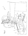
- the heat-sealing machine 1 comprises a conveying group 4 comprising a first conveying member 4a co-operating with a second conveying member 4b for translation of the article of manufacture 2 being worked, in a predetermined feeding direction A ( Fig. 1 ).
- the first and second layers 2a, 2b of the article of manufacture 2 being worked are interposed between the first and second conveying members 2a, 2b in a region of mutual junction of the layers themselves.
- At least one thermoadhesive element 3 is carried by at least one of the layers on the side facing the other layer in the region of mutual junction.
- the first and second conveying members 4a, 4b are arranged one above the other with the interposition of the article of manufacture 2 being worked sliding along a plane which is horizontal or inclined with respect to the horizontal.
- the conveying group 4 comprises a drive member 4a, co-operating with a counter-member 4b for translating the article of manufacture 2 being worked, in the predetermined feeding direction A.
- the counter-member 4b is arranged above the drive member 4a.
- An alternative solution may also be envisaged where the counter-member 4b is arranged below the drive member 4a.
- the counter-member 4b is formed by means of an idle roller and the drive member 4a is formed by means of a belt wound around rollers at least one of which is motor-driven.
- the counter-member 4b may be formed by means of a belt wound around rollers.
- the drive member 4a may be formed by means of a motor-driven roller.
- the heat-sealing machine 1 comprises a guide 5 suitable for supporting the two layers of the article of manufacture 2 being worked with, interposed, the thermoadhesive element 3, so as to move towards the conveying group 4.
- the guide 5 is, for example, formed by means of a support surface which accompanies the article of manufacture 2 towards the conveying group 4.
- the first conveying member 4a is substantially incorporated in the guide 5 so as to operate flush therewith, and the second conveying member 4b is arranged above the guide 5.
- the heat-sealing machine 1 also comprises a heating unit 6 operating in the region of the conveying group 4.
- the heating unit 6 is designed to cause activation of the thermoadhesive element 3 carried by at least one of the layers 2a, 2b on the side facing the other layer in the region of mutual junction.
- the heating unit 6 comprises a heat dispenser 7 operating between the first and second layers 2a, 2b so as to direct a thermal carrier flux directly against the thermoadhesive element 3.
- the thermal carrier flow is directed towards the conveying group 4.
- the heat dispenser 7 is inserted partly between the first and second textile layers 2a, 2b of the article of manufacture 2 being worked.
- the heat dispenser 7 operates between the first and second layers 2a, 2b in a position immediately upstream of the conveying group 4.
- the heat dispenser 7 comprises a delivery nozzle 8 operatively connected to a hot-air generating unit 9.
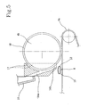
- the delivery nozzle 8 comprises a tubular element 10 having a longitudinal extension axis 11 substantially perpendicular to the feeding direction A of the article of manufacture 2 and having at least one outlet hole 12 oriented towards the conveying group 4 ( Figure 5 ).
- the delivery nozzle 8 is arranged laterally relative to the feeding direction A in the zone where the free end of the upper layer 2b is arranged.
- the delivery nozzle 8 is arranged with its longitudinal axis 11 substantially horizontal or slightly inclined relative to the horizontal.
- the delivery nozzle 8 is arranged with at least one end portion substantially parallel to the guide 5.
- the heat dispenser 7 may be transversely movable relative to the feeding direction A of the article of manufacture 2 being worked, preferably in a horizontal direction and/or substantially along its longitudinal axis.
- the dispenser 7 may be displaced, upon operation of an actuator 20 operating on a slide 21 carrying the dispenser itself, between an operating condition in which it is disposed upstream of the conveying group 4, with reference to the feeding direction A of the article of manufacture (as shown in the accompanying figures), and a rest condition in which it is laterally shifted relative to the conveying group 4 itself, so as not to hinder introduction of the article of manufacture 2 between the conveying members 4a, 4b during the initial stage of working.
- the term "laterally” is understood as meaning a position radially displaced relative to the feeding direction A of the article of manufacture. In the case illustrated, the dispenser 7 in the rest condition is laterally positioned to the right relative to the working condition shown.
- the heating unit 6 also comprises a second heat dispenser 13 designed to direct a second thermal carrier flux towards the conveying group 4, in particular towards the drive member 4a and the counter-member 4b, above the article of manufacture 2 being worked.
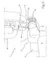
- the second heat dispenser 13 comprises a fixed conveyor 14 operating close to the conveying group 4, and a second delivery nozzle 15 operatively connected to a hot-air generating unit 16.
- the delivery nozzle 15 is preferably movable between a rest condition in which it is laterally moved away from the conveying group 4, to the right thereof with reference to Figure 1 , and a working condition in which it is operatively coupled to the fixed conveyor 14, as per the accompanying figures.
- the fixed conveyor 14 operates close to the conveying member arranged above. More particularly, the fixed conveyor 14 operates close to the counter member 4b.
- the fixed conveyor 14 has an inlet opening 14a adapted to receive the hot-air flow from the second delivery nozzle 15 positioned in the working condition and an outlet opening 14b which is situated facing above the article of manufacture 2 being worked and directs the hot-air jet towards at least one of the conveying members, in particular towards the counter-member 4b ( Figure 6).
- the fixed conveyor 14 is partially wrapped around at least one of the conveying members, preferably the counter-member 4b, and comprises an open seat 17 for receiving a portion of the conveying member.
- the open seat 17 is placed in communication with the inlet opening 14a for the hot-air flow and defines the outlet opening 14b of the fixed conveyor 14.
- the fixed conveyor 14 has a C-shaped form which partially embraces the conveying member, in particular the counter-member 4b, receiving the hot-ait flow from the outside via the inlet opening 14a and distributing it over the outer surface of the conveying member ( Figure 6).
- At least one of the first and second conveying members 4a, 4b comprises an outer surface 18 suitable for acting against the article of manufacture 2 being worked and made of thermally conductive, preferably metallic, material.
- the outer surface is made of copper.
- the conveying member having the abovementioned outer surface made of a thermally conductive, preferably metallic, material is the idly mounted counter-member 4b.
- the conveying member having the abovementioned outer surface made of a thermally conductive, preferably metallic, material is the member arranged above.
- this fixed conveyor 14 it is preferable for this fixed conveyor 14 to operate close to the conveying member having the abovementioned outer surface 18 made of a thermally conductive, preferably metallic, material. As shown in Figure 1 , the fixed conveyor 14 operates close to the counter-member 4b having the abovementioned outer surface 4b made of a thermally conductive material.
- the outer surface made of thermally conductive material may be provided on the drive member 4a.
- this thermally conductive material is a metallic material.
- the drive member 4a acts against the article of manufacture 2 being worked, by means of an outer surface made of copper.
- the heat-sealing machine 1 may also comprise control means which can be selectively activated for performing the movement, preferably the translation, of the heat dispenser 7 towards the respective operating condition, simultaneously or with a predetermined advance relative to operation of the conveying group 4.
- control means which can be selectively activated for performing the movement, preferably the translation, of the heat dispenser 7 towards the respective operating condition, simultaneously or with a predetermined advance relative to operation of the conveying group 4.
- the control means induce heating of the article of manufacture by means of the heat dispenser 7 simultaneously or with a predetermined advance relative to operation of the conveying group 4.
- control means which can be selectively activated for performing the movement of the second heat dispenser 13 towards the respective operating condition with a predetermined advance, preferably of between 1 and 5 seconds, relative to operation of the conveying group 4.
- control means induce heating of the article of manufacture by means of the heat dispenser 13 with a predetermined advance relative to operation of the conveying group 4.
- a standard control unit forms the abovementioned control means which controls the movement both of the heat dispenser 7 and of the second heat dispenser 13, for example by means of operation of a pedal by the user.
- thermoadhesive element 3 a first surface of the thermoadhesive element 3 is glued to the first textile layer 2a, for example the layer arranged underneath with reference to the figures. Then the second adhesive layer of the thermoadhesive element 3 is exposed and the second layer 2b (in the figure for example the upper layer) is partially superimposed on the first layer in the region of the thermoadhesive element 3.
- the end portion of the article of manufacture 2 being worked is inserted between the two conveying members 4a, 4b, while an operator accompanies the two layers 2a, 2b along the guide 5 and operates the heat-sealing machine.
- control means move the second heat dispenser 13 towards the respective operating condition with a predetermined advance, preferably of between 1 and 5 seconds, relative to operation of the conveying group 4. Then the heat dispenser 7 is moved and the conveying group 4 is operated.
- the movement of the second heat dispenser 13 is preferably performed by means of angular oscillation about a fixed point, while the movement of the heat dispenser 7 is performed preferably by means of translation along a preferably horizontal plane. Variations of these forms of movement are, however, possible.
- the heat dispensers are preferably always in operation in order to prevent activation delays, so that the displacement towards the article of manufacture coincides with activation of heating of the article of manufacture itself.
- the hot-air flow of the second heat dispenser 13 surrounds the counter-member 4b and heats the outer surface 18 which improves the adhesion of the two layers 2a, 2b in the region of the front or end portion of the article of manufacture itself.
- the second heat dispenser 13 continues to heat the counter-member 4b, but the main heating action for causing adhesion of the two layers 2a, 2b is performed by the heat dispenser 7 directly inserted between the two layers 2a, 2b of the article of manufacture.
- the heat-sealing machine may be set up independently of the type of layers 2a, 2b being worked since the action of the heat flow does not pass through the upper layer but acts directly on the thermoadhesive element 3.
- the conveying group 4 conveys the article of manufacture 2 being worked and exerts a simultaneous pressure which favours adhesion by the thermoadhesive element 3 heated immediately upstream of the conveying group 4 itself.
- the present invention relates to a method for assembling textile articles, wherein a first and a second layer 2a, 2b of the article of manufacture 2 which overlap each other at least in a region of mutual junction are subjected to a heating action in the junction region for determining activation of a thermoadhesive element 3 provided on a surface of at least one of the layers 2a, 2b facing the other layer, for determining stable coupling of the layers 2a, 2b by the heat-activated thermoadhesive element 3.
- the heating action is performed preferably in combination with a pressing action at least in the junction region.
- the heating action is carried out by conveying thermal energy between the first and second layers 2a, 2b by means of at least one heat dispenser 13 interposed between the first and second layers 2a, 2b upstream of the conveying group 4 operating in the region of mutual junction so as to cause feeding of the layers 2a, 2b through a work region.
- the heating action is further carried out by conveying thermal energy with a second thermal carrier flux towards the conveying group 4.
- the heating action is further carried out by conveying thermal energy with a second thermal carrier flux towards at least one of the conveying members and transferring it to the thermoadhesive element 3 by means of conduction using an outer surface, made of thermally conductive material, of the conveying member itself.
- the second thermal carrier flux is conveyed towards the conveying group 4 with a predetermined advance, preferably of between 1 and 5 relative to operation of the conveying group 4.
- the thermal energy is conveyed between the first and second layers 2a, 2b by means of at least one heat dispenser 13 interposed between the first and second layers 2a, 2b upstream of the conveying group 4 simultaneously or with a predetermined advance relative to operation of the conveying group 4 itself.
- thermoadhesive element 3 As already stated previously, the original provision of a heat dispenser 13 operating between the first and second layers 2a, 2b so as to direct a thermal carrier flux directly towards the thermoadhesive element 3 allows an improvement in the heating efficiency and elimination of operating variables due to the type of layer used. This aspect is particularly advantageous in the case of a delivery nozzle 15 operatively connected to a hot-air generating unit 16 which forms a system which is simple, but in particular subject to the variables in question.
- the delivery nozzle 15 in the form of a tubular element having a longitudinal extension axis substantially perpendicular to a feeding direction of the article of manufacture 2 being worked and having at least one outlet hole oriented towards the conveying group 4, a solid, simple and effective structure able to direct the thermal flux directly onto the thermoadhesive element 3 between the two layers 2a, 2b, without introducing excessive complications, is obtained.
- a movable heat dispenser 13 results in an improvement in the operating efficiency, since the heat dispenser 13 is kept always operational and heating of the article of manufacture is activated depending on its position.
- the second heat dispenser 13 designed to direct a second thermal carrier flux towards the conveying group 4 improves and ensures generally more uniform adhesion of the two layers 2a, 2b, in particular along the end edge of the article of manufacture, not directly acted on by the flux of the heat dispenser 7 arranged directly between the two layers 2a, 2b.
- the fixed conveyor 14 operating close to the conveying group 4 ensures optimized diffusion of the thermal flux over the conveying member and, with the aid of the continuous delivery, avoids delays during activation. Moreover, owing to the presence of a fixed conveyor 14, it is possible to design specifically a form of the fixed conveyor itself 14 suitable for distributing in an optimum manner the thermal flux over the conveying member.
- This aspect is particularly advantageous in the case where further heating of the article of manufacture is performed by means of conduction, for example with the provision of an outer conducting surface of the conveying member.
- provision of an outer conducting surface of the conveying member offers advantages associated with the fact of being able to apply a pressure and perform corresponding heating in the zone which passes through the conveying member 4. In this way a uniform adhesion is obtained, without damaging the fabric as a result of excessive heating.
Landscapes
- Engineering & Computer Science (AREA)
- Mechanical Engineering (AREA)
- Physics & Mathematics (AREA)
- Thermal Sciences (AREA)
- Textile Engineering (AREA)
- Chemical & Material Sciences (AREA)
- Combustion & Propulsion (AREA)
- Treatment Of Fiber Materials (AREA)
- Lining Or Joining Of Plastics Or The Like (AREA)
Claims (14)
- Heißsiegelmaschine für die Montage von gefertigten Textilartikeln, umfassend:- eine Fördergruppe (4), umfassend ein erstes Förderelement (4a), das mit einem zweiten Förderelement (4b) zusammenwirkt, zur Verschiebung eines zu bearbeitenden gefertigten Artikels (2) in eine vorgegebene Zuführrichtung (A), wobei der gefertigte Artikel (2) mindestens eine erste und eine zweite Schicht (2a, 2b) umfasst, die dazu geeignet sind, zwischen der ersten und zweiten Förderelemente (4a, 4b) in einem Bereich gegenseitiger Verbindung der Schichten selbst eingefügt zu werden;- eine Erwärmungseinheit (6), die im Bereich der Fördergruppe (4) wirkt, zur Bewirkung der Aktivierung mindestens eines heißklebenden Elements (3), das durch mindestens eine der Schichten (2a, 2b) an einer Seite davon getragen ist, die im Bereich gegenseitiger Verbindung der anderen Schicht (2a, 2b) zugewandt ist, wobei die Erwärmungseinheit (6) einen Wärmespender (7) umfasst, der in eine horizontale Richtung quer zur Zuführrichtung (A) des zu bearbeitenden gefertigten Artikels (2), zwischen einem Betriebszustand, in dem er mit Bezug auf die Zuführrichtung (A) des gefertigten Artikels (2) der Fördergruppe (4) vorgelagert ist, und einem Ruhezustand, in dem er relativ zu der Fördergruppe selbst seitlich verschoben ist, bewegbar ist, wobei der Wärmespender (7) dazu geeignet ist, zwischen der ersten und zweiten Schichten (2a, 2b) zu wirken, um eine thermische Trägerströmung gegen das heißklebende Element (3) zu richten, wobei die Erwärmungseinheit zudem einen zweiten Wärmespender (13) umfasst, der dazu ausgestaltet ist, eine zweite thermische Trägerströmung auf die Fördergruppe (4) zu richten.
- Maschine nach Anspruch 1, wobei der Wärmespender (7) eine Abgabedüse (8) umfasst, die mit einer Heißlufterzeugungseinheit (16) betriebswirksam verbunden ist, wobei die Abgabedüse (8) ein Rohrelement (16) umfasst, das eine Längsausdehnungsachse (11) aufweist, die im Wesentlichen senkrecht zur Zuführrichtung (A) des zu bearbeitenden gefertigten Artikels (2) ist, und das mit mindestens einem zur Fördergruppe (4) ausgerichteten Auslassloch (12) versehen ist.
- Maschine nach Anspruch 1, wobei der zweite Wärmespender (13) einen festen Förderer (14), der in der Nähe der Fördergruppe (4) wirkt, und eine zweite Abgabedüse (15) umfasst, die mit einer Heißlufterzeugungseinheit (16) betriebswirksam verbunden ist und zwischen einem Ruhezustand, in dem diese von der Fördergruppe (4) seitlich wegführend bewegt wird, und einem Arbeitszustand bewegbar ist, in dem diese mit dem festen Förderer (14) betriebswirksam gekoppelt ist.
- Maschine nach dem vorhergehenden Anspruch, wobei der feste Förderer (14) eine Einlassöffnung (14a), die dazu geeignet ist, in dem Arbeitszustand die Heißluftströmung von der zweiten Abgabedüse (15) aufzunehmen, und eine Auslassöffnung (14b), die den Heißluftstrahl auf mindestens eines der Förderelemente (4a, 4b) richtet, aufweist.
- Maschine nach Anspruch 3 oder 4, wobei der feste Förderer (14) teilweise mindestens eines der Förderelemente (4a, 4b) umgibt und ein offenes Gehäuse (17) zur Aufnahme eines Abschnitts des Förderelements (4a, 4b) umfasst, wobei das offene Gehäuse (17) in Kommunikation mit einer Einlassöffnung (14a) für die Heißluftströmung gebracht wird und wobei das offene Gehäuse (17) eine Auslassöffnung (14b) des festen Förderers (14) definiert.
- Maschine nach einem oder mehreren der vorhergehenden Ansprüche, wobei mindestens eines der ersten und zweiten Förderelemente (4a, 4b) eine aus thermisch leitfähigem Metallmaterial bestehende Äußerfläche (18) umfasst, die dazu geeignet ist, gegen den zu bearbeitenden gefertigten Artikel (2) einzuwirken.
- Maschine nach einem der Ansprüche 3 bis 5 und nach Anspruch 6, wobei der feste Förderer (14) in der Nähe des Förderelements (4a, 4b), aufweisend die aus thermisch leitfähigem Metallmaterial bestehenden Äußerfläche (18), einwirkt.
- Maschine nach Anspruch 7, wobei das Förderelement (4a, 4b), aufweisend die aus thermisch leitfähigem Metallmaterial bestehenden Äußerfläche (18), ein im Leerlauf montiertes Gegenelement ist.
- Maschine nach Anspruch 1, zudem umfassend Steuermittel, die selektiv aktiviert werden können, um die Bewegung des Wärmespenders (7) zum jeweiligen Betriebszustand gleichzeitig mit oder auf vorgegebener Weise im Voraus relativ zum Betrieben der Fördergruppe (4) auszuführen.
- Maschine nach Anspruch 3, zudem umfassend Steuermittel, die selektiv aktiviert werden können, um die Bewegung des zweiten Wärmespenders (13) zum jeweiligen Betriebszustand auf vorgegebener Weise im Voraus relativ zum Betrieben der Fördergruppe (4) auszuführen.
- Verfahren für die Montage von gefertigten Textilartikeln, wobei eine erste und eine zweite Schicht (2a, 2b) des gefertigten Artikels (2), die sich aufeinander mindestens in einem Bereich gegenseitiger Verbindung überlappen, einer Heizwirkung im Verbindungsbereich unterzogen werden, um die Aktivierung des heißklebenden Elements (3), das sich auf einer Fläche mindestens einer der Schichten (2a, 2b) befindet, die der anderen Schicht (2a, 2b) zugewandt ist, zu bewirken, um eine stetige Verkopplung der Schichten (2a, 2b) durch das thermoaktivierte heißklebende Element (3) zu bewirken, wobei die Heizwirkung unter Beförderung thermischer Energie zwischen der ersten und zweiten Schichten (2a, 2b) durch mindestens einen der Fördergruppe (4) vorgelagerten, zwischen der ersten und zweiten Schichten (2a, 2b) eingefügten Wärmespender (7) durchgeführt wird, der im Bereich gegenseitiger Verbindung wirkt, um eine Zuführung der Schichten (2a, 2b) durch einen Arbeitsbereich zu verursachen, und wobei die Heizwirkung zudem unter Beförderung thermischer Energie mit einer zweiten thermischen Trägerströmung zur Fördergruppe (4) durchgeführt wird.
- Verfahren für die Montage von gefertigten Textilartikeln nach Anspruch 11, wobei die Heizwirkung zudem unter Beförderung thermischer Energie mit der zweiten thermischen Trägerströmung zu mindestens einem der Förderelemente (4a, 4b) und unter Übertragung dieser auf das heißklebende Element (3) durch Leitung unter Nutzung einer aus thermisch leitfähigem Metallmaterial bestehenden Äußerfläche (18) des Förderelements (4a, 4b) durchgeführt wird.
- Verfahren für die Montage von gefertigten Textilartikeln nach Anspruch 11 oder 12, wobei die zweite thermische Trägerströmung auf vorgegebener Weise im Voraus relativ zum Betrieben der Fördergruppe (4) zur Fördergruppe (4) befördert wird.
- Verfahren für die Montage von gefertigten Textilartikeln nach einem der Ansprüche 11 bis 13, wobei die thermische Energie durch mindestens einen der Fördergruppe (4) vorgelagerten, zwischen der ersten und zweiten Schichten (2a, 2b) eingefügten Wärmespender (7) gleichzeitig mit oder auf vorgegebener Weise im Voraus relativ zum Betrieben der Fördergruppe (4) zwischen der ersten und zweiten Schichten (2a, 2b) befördert wird.
Applications Claiming Priority (2)
| Application Number | Priority Date | Filing Date | Title |
|---|---|---|---|
| ITMI2009A002098A IT1396634B1 (it) | 2009-11-27 | 2009-11-27 | Macchina termosaldatrice per l'assemblaggio di manufatti tessili, e metodo da essa attuato |
| PCT/IB2010/055328 WO2011064711A2 (en) | 2009-11-27 | 2010-11-22 | Heat-sealing machine for assembling textile articles of manufacture and method achieved by the same |
Publications (2)
| Publication Number | Publication Date |
|---|---|
| EP2504151A2 EP2504151A2 (de) | 2012-10-03 |
| EP2504151B1 true EP2504151B1 (de) | 2015-07-22 |
Family
ID=42286716
Family Applications (1)
| Application Number | Title | Priority Date | Filing Date |
|---|---|---|---|
| EP10816374.2A Active EP2504151B1 (de) | 2009-11-27 | 2010-11-22 | Heisssiegelmaschine für die montage von textilartikeln und damit ausgeführtes verfahren |
Country Status (6)
| Country | Link |
|---|---|
| EP (1) | EP2504151B1 (de) |
| KR (1) | KR101852145B1 (de) |
| CN (1) | CN102695597B (de) |
| IT (1) | IT1396634B1 (de) |
| PT (1) | PT2504151E (de) |
| WO (1) | WO2011064711A2 (de) |
Families Citing this family (4)
| Publication number | Priority date | Publication date | Assignee | Title |
|---|---|---|---|---|
| CN102283456B (zh) * | 2011-08-23 | 2013-06-12 | 鲁泰纺织股份有限公司 | 制衣喷胶设备 |
| CN104997221A (zh) * | 2015-07-20 | 2015-10-28 | 英商马田纺织品(中国-中山)有限公司 | 一种皮带折边机 |
| US20190100860A1 (en) * | 2017-09-29 | 2019-04-04 | Columbia Insurance Company | Guard inserts and systems and methods of using same |
| CN111685403B (zh) * | 2020-07-14 | 2022-08-09 | 安徽甬安雨具有限公司 | 一种雨衣生产用衣袖热合装置 |
Family Cites Families (16)
| Publication number | Priority date | Publication date | Assignee | Title |
|---|---|---|---|---|
| US2117452A (en) * | 1932-09-08 | 1938-05-17 | Us Rubber Co | Cut seaming machine |
| US3530027A (en) * | 1968-08-08 | 1970-09-22 | M & B Headwear Co Inc | Thermo adhesive tape applicator |
| DE2011925A1 (de) * | 1970-03-13 | 1971-09-30 | Kannegiesser Maschinenfabrik Gmbh, 4973 Vlotho | Verfahren und Vorrichtung zum Verkleben von flachenförmigen Textilstucken |
| US4067761A (en) * | 1976-12-20 | 1978-01-10 | The Kartridg Pak Co. | Plastic web sealing apparatus using hot air heated sealing roller |
| US4608114A (en) * | 1984-04-10 | 1986-08-26 | Queen Light Of Electronic Industries Ltd. | Seal tape sticking device |
| US4685389A (en) * | 1985-01-25 | 1987-08-11 | Measurex Corporation | Hot air calender roll controller |
| DE3838145C1 (de) * | 1988-11-10 | 1990-04-26 | Pfaff Industriemaschinen Gmbh, 6750 Kaiserslautern, De | |
| US6471803B1 (en) * | 1997-10-24 | 2002-10-29 | Ray Pelland | Rotary hot air welder and stitchless seaming |
| GB2332389B (en) * | 1997-12-19 | 2002-02-27 | Pfaff Ag G M | Hot-sealing machine |
| AU3066099A (en) * | 1998-05-01 | 1999-11-23 | W.L. Gore & Associates, Inc. | Repeatably positionable nozzle assembly |
| ITMI20012622A1 (it) * | 2001-12-12 | 2003-06-12 | Saltek Engineering S R L | Macchina per l'applicazione a caldo di nastri o filò rigidi e/o elastici su supporti tessili e non |
| CN2766598Y (zh) * | 2005-01-28 | 2006-03-29 | 张永兴 | 热风压合机 |
| JP4664096B2 (ja) * | 2005-03-04 | 2011-04-06 | 藤倉航装株式会社 | 防水性縫い目用シーリング機 |
| US7267154B1 (en) * | 2006-06-20 | 2007-09-11 | Kuen-Yuan Hung | Water-proof film laminating machine |
| ITMI20070300A1 (it) * | 2007-02-16 | 2008-08-17 | Macpi Pressing Div | Impianto e metodo per orlare un tessuto senza uso di cuciture inserendo un elastico adesivizzato in corrispondenza di una o due superfici opposte dello stesso |
| ITMI20080342A1 (it) * | 2008-02-29 | 2009-09-01 | Macpi Pressing Division Spa | Macchina modulare atta ad eseguire l'assemblaggio di due tessuti mediante adesivazione con o senza nastratura. |
-
2009
- 2009-11-27 IT ITMI2009A002098A patent/IT1396634B1/it active
-
2010
- 2010-11-22 WO PCT/IB2010/055328 patent/WO2011064711A2/en not_active Ceased
- 2010-11-22 CN CN201080060407.3A patent/CN102695597B/zh active Active
- 2010-11-22 EP EP10816374.2A patent/EP2504151B1/de active Active
- 2010-11-22 KR KR1020127016754A patent/KR101852145B1/ko not_active Expired - Fee Related
- 2010-11-22 PT PT108163742T patent/PT2504151E/pt unknown
Also Published As
| Publication number | Publication date |
|---|---|
| CN102695597A (zh) | 2012-09-26 |
| ITMI20092098A1 (it) | 2011-05-28 |
| PT2504151E (pt) | 2015-10-19 |
| WO2011064711A3 (en) | 2011-08-11 |
| IT1396634B1 (it) | 2012-12-14 |
| EP2504151A2 (de) | 2012-10-03 |
| KR101852145B1 (ko) | 2018-04-26 |
| WO2011064711A2 (en) | 2011-06-03 |
| CN102695597B (zh) | 2015-10-21 |
| KR20120107101A (ko) | 2012-09-28 |
Similar Documents
| Publication | Publication Date | Title |
|---|---|---|
| EP2504151B1 (de) | Heisssiegelmaschine für die montage von textilartikeln und damit ausgeführtes verfahren | |
| US8863804B2 (en) | Device for coating a workpiece | |
| US20010013395A1 (en) | Flatbed lamination machine | |
| US20210130995A1 (en) | Attachment for Sealing Seams | |
| KR19990044117A (ko) | 직물 등의 천 조각 2개를 결합시키는 방법 및 장치와, 이에 의해 얻어지는 의류 제품 등의 제품 | |
| CN102312373A (zh) | 用于接合或带接合纺织物的设备 | |
| CN103287049B (zh) | 用于制造复合材料的方法和装置 | |
| KR102124281B1 (ko) | 복합원단 제조장치 및 그에 의해 제조된 복합원단 | |
| KR20130037149A (ko) | 천연가죽 라미네이팅 방법 및 이를 이용한 천연가죽 시트 | |
| EP4378667A1 (de) | Vorrichtung und verfahren zum aufbringen eines bandes auf gewebe oder ähnliche produkte | |
| Petrie | Alternative fabric-joining technologies | |
| CN101843379B (zh) | 接合机 | |
| EP1624766B1 (de) | Falzmaschine | |
| EP4230386B1 (de) | Verbindungsvorrichtung für folienförmige materialien | |
| JP4145522B2 (ja) | 接合すべきプラスチックフィルムの温調をする方法、及び温度制御された搬送ロールを用いてプラスチックフィルムを接合する装置 | |
| KR101311845B1 (ko) | 봉제장치 | |
| JP7471627B2 (ja) | 自動縫製装置および縫合装置 | |
| KR20100001646U (ko) | 마감재용 접착제 도포장치 | |
| US9375875B2 (en) | Method for processing thermoplastic films, thermoforming system, film supply station, film strip, use, and laminated part | |
| JP5889830B2 (ja) | 化粧材の接着方法及び被覆製品の製造方法 | |
| KR101311844B1 (ko) | 봉제장치 | |
| CN108116929A (zh) | 粘接装置和粘接装置的控制方法 | |
| US20010011572A1 (en) | Device for sealing stitching threads | |
| HK1118676A1 (zh) | 用於给布料缝折边的缝折边系统和方法 | |
| HK1118676B (zh) | 用於给布料缝折边的缝折边系统和方法 |
Legal Events
| Date | Code | Title | Description |
|---|---|---|---|
| PUAI | Public reference made under article 153(3) epc to a published international application that has entered the european phase |
Free format text: ORIGINAL CODE: 0009012 |
|
| 17P | Request for examination filed |
Effective date: 20120515 |
|
| AK | Designated contracting states |
Kind code of ref document: A2 Designated state(s): AL AT BE BG CH CY CZ DE DK EE ES FI FR GB GR HR HU IE IS IT LI LT LU LV MC MK MT NL NO PL PT RO RS SE SI SK SM TR |
|
| DAX | Request for extension of the european patent (deleted) | ||
| 17Q | First examination report despatched |
Effective date: 20140527 |
|
| GRAP | Despatch of communication of intention to grant a patent |
Free format text: ORIGINAL CODE: EPIDOSNIGR1 |
|
| INTG | Intention to grant announced |
Effective date: 20150217 |
|
| RAP1 | Party data changed (applicant data changed or rights of an application transferred) |
Owner name: FRA-SER S.P.A. |
|
| GRAS | Grant fee paid |
Free format text: ORIGINAL CODE: EPIDOSNIGR3 |
|
| GRAA | (expected) grant |
Free format text: ORIGINAL CODE: 0009210 |
|
| AK | Designated contracting states |
Kind code of ref document: B1 Designated state(s): AL AT BE BG CH CY CZ DE DK EE ES FI FR GB GR HR HU IE IS IT LI LT LU LV MC MK MT NL NO PL PT RO RS SE SI SK SM TR |
|
| REG | Reference to a national code |
Ref country code: GB Ref legal event code: FG4D |
|
| REG | Reference to a national code |
Ref country code: CH Ref legal event code: EP |
|
| REG | Reference to a national code |
Ref country code: IE Ref legal event code: FG4D |
|
| REG | Reference to a national code |
Ref country code: AT Ref legal event code: REF Ref document number: 737629 Country of ref document: AT Kind code of ref document: T Effective date: 20150815 |
|
| REG | Reference to a national code |
Ref country code: DE Ref legal event code: R096 Ref document number: 602010026118 Country of ref document: DE |
|
| REG | Reference to a national code |
Ref country code: CH Ref legal event code: NV Representative=s name: BUGNION S.A., CH |
|
| REG | Reference to a national code |
Ref country code: PT Ref legal event code: SC4A Free format text: AVAILABILITY OF NATIONAL TRANSLATION Effective date: 20150922 |
|
| REG | Reference to a national code |
Ref country code: FR Ref legal event code: PLFP Year of fee payment: 6 |
|
| REG | Reference to a national code |
Ref country code: AT Ref legal event code: MK05 Ref document number: 737629 Country of ref document: AT Kind code of ref document: T Effective date: 20150722 |
|
| REG | Reference to a national code |
Ref country code: LT Ref legal event code: MG4D |
|
| REG | Reference to a national code |
Ref country code: NL Ref legal event code: MP Effective date: 20150722 |
|
| PG25 | Lapsed in a contracting state [announced via postgrant information from national office to epo] |
Ref country code: LT Free format text: LAPSE BECAUSE OF FAILURE TO SUBMIT A TRANSLATION OF THE DESCRIPTION OR TO PAY THE FEE WITHIN THE PRESCRIBED TIME-LIMIT Effective date: 20150722 Ref country code: LV Free format text: LAPSE BECAUSE OF FAILURE TO SUBMIT A TRANSLATION OF THE DESCRIPTION OR TO PAY THE FEE WITHIN THE PRESCRIBED TIME-LIMIT Effective date: 20150722 Ref country code: GR Free format text: LAPSE BECAUSE OF FAILURE TO SUBMIT A TRANSLATION OF THE DESCRIPTION OR TO PAY THE FEE WITHIN THE PRESCRIBED TIME-LIMIT Effective date: 20151023 Ref country code: NO Free format text: LAPSE BECAUSE OF FAILURE TO SUBMIT A TRANSLATION OF THE DESCRIPTION OR TO PAY THE FEE WITHIN THE PRESCRIBED TIME-LIMIT Effective date: 20151022 Ref country code: FI Free format text: LAPSE BECAUSE OF FAILURE TO SUBMIT A TRANSLATION OF THE DESCRIPTION OR TO PAY THE FEE WITHIN THE PRESCRIBED TIME-LIMIT Effective date: 20150722 |
|
| PG25 | Lapsed in a contracting state [announced via postgrant information from national office to epo] |
Ref country code: RS Free format text: LAPSE BECAUSE OF FAILURE TO SUBMIT A TRANSLATION OF THE DESCRIPTION OR TO PAY THE FEE WITHIN THE PRESCRIBED TIME-LIMIT Effective date: 20150722 Ref country code: SE Free format text: LAPSE BECAUSE OF FAILURE TO SUBMIT A TRANSLATION OF THE DESCRIPTION OR TO PAY THE FEE WITHIN THE PRESCRIBED TIME-LIMIT Effective date: 20150722 Ref country code: IS Free format text: LAPSE BECAUSE OF FAILURE TO SUBMIT A TRANSLATION OF THE DESCRIPTION OR TO PAY THE FEE WITHIN THE PRESCRIBED TIME-LIMIT Effective date: 20151122 Ref country code: AT Free format text: LAPSE BECAUSE OF FAILURE TO SUBMIT A TRANSLATION OF THE DESCRIPTION OR TO PAY THE FEE WITHIN THE PRESCRIBED TIME-LIMIT Effective date: 20150722 Ref country code: ES Free format text: LAPSE BECAUSE OF FAILURE TO SUBMIT A TRANSLATION OF THE DESCRIPTION OR TO PAY THE FEE WITHIN THE PRESCRIBED TIME-LIMIT Effective date: 20150722 Ref country code: HR Free format text: LAPSE BECAUSE OF FAILURE TO SUBMIT A TRANSLATION OF THE DESCRIPTION OR TO PAY THE FEE WITHIN THE PRESCRIBED TIME-LIMIT Effective date: 20150722 Ref country code: PL Free format text: LAPSE BECAUSE OF FAILURE TO SUBMIT A TRANSLATION OF THE DESCRIPTION OR TO PAY THE FEE WITHIN THE PRESCRIBED TIME-LIMIT Effective date: 20150722 |
|
| REG | Reference to a national code |
Ref country code: DE Ref legal event code: R097 Ref document number: 602010026118 Country of ref document: DE |
|
| PG25 | Lapsed in a contracting state [announced via postgrant information from national office to epo] |
Ref country code: IT Free format text: LAPSE BECAUSE OF FAILURE TO SUBMIT A TRANSLATION OF THE DESCRIPTION OR TO PAY THE FEE WITHIN THE PRESCRIBED TIME-LIMIT Effective date: 20150722 Ref country code: EE Free format text: LAPSE BECAUSE OF FAILURE TO SUBMIT A TRANSLATION OF THE DESCRIPTION OR TO PAY THE FEE WITHIN THE PRESCRIBED TIME-LIMIT Effective date: 20150722 Ref country code: CZ Free format text: LAPSE BECAUSE OF FAILURE TO SUBMIT A TRANSLATION OF THE DESCRIPTION OR TO PAY THE FEE WITHIN THE PRESCRIBED TIME-LIMIT Effective date: 20150722 Ref country code: DK Free format text: LAPSE BECAUSE OF FAILURE TO SUBMIT A TRANSLATION OF THE DESCRIPTION OR TO PAY THE FEE WITHIN THE PRESCRIBED TIME-LIMIT Effective date: 20150722 Ref country code: SK Free format text: LAPSE BECAUSE OF FAILURE TO SUBMIT A TRANSLATION OF THE DESCRIPTION OR TO PAY THE FEE WITHIN THE PRESCRIBED TIME-LIMIT Effective date: 20150722 |
|
| PLBE | No opposition filed within time limit |
Free format text: ORIGINAL CODE: 0009261 |
|
| STAA | Information on the status of an ep patent application or granted ep patent |
Free format text: STATUS: NO OPPOSITION FILED WITHIN TIME LIMIT |
|
| PG25 | Lapsed in a contracting state [announced via postgrant information from national office to epo] |
Ref country code: RO Free format text: LAPSE BECAUSE OF FAILURE TO SUBMIT A TRANSLATION OF THE DESCRIPTION OR TO PAY THE FEE WITHIN THE PRESCRIBED TIME-LIMIT Effective date: 20150722 |
|
| 26N | No opposition filed |
Effective date: 20160425 |
|
| PG25 | Lapsed in a contracting state [announced via postgrant information from national office to epo] |
Ref country code: MC Free format text: LAPSE BECAUSE OF FAILURE TO SUBMIT A TRANSLATION OF THE DESCRIPTION OR TO PAY THE FEE WITHIN THE PRESCRIBED TIME-LIMIT Effective date: 20150722 Ref country code: LU Free format text: LAPSE BECAUSE OF FAILURE TO SUBMIT A TRANSLATION OF THE DESCRIPTION OR TO PAY THE FEE WITHIN THE PRESCRIBED TIME-LIMIT Effective date: 20151122 |
|
| REG | Reference to a national code |
Ref country code: IE Ref legal event code: MM4A |
|
| PG25 | Lapsed in a contracting state [announced via postgrant information from national office to epo] |
Ref country code: SI Free format text: LAPSE BECAUSE OF FAILURE TO SUBMIT A TRANSLATION OF THE DESCRIPTION OR TO PAY THE FEE WITHIN THE PRESCRIBED TIME-LIMIT Effective date: 20150722 |
|
| PG25 | Lapsed in a contracting state [announced via postgrant information from national office to epo] |
Ref country code: IE Free format text: LAPSE BECAUSE OF NON-PAYMENT OF DUE FEES Effective date: 20151122 |
|
| REG | Reference to a national code |
Ref country code: FR Ref legal event code: PLFP Year of fee payment: 7 |
|
| PG25 | Lapsed in a contracting state [announced via postgrant information from national office to epo] |
Ref country code: BE Free format text: LAPSE BECAUSE OF FAILURE TO SUBMIT A TRANSLATION OF THE DESCRIPTION OR TO PAY THE FEE WITHIN THE PRESCRIBED TIME-LIMIT Effective date: 20150722 |
|
| PG25 | Lapsed in a contracting state [announced via postgrant information from national office to epo] |
Ref country code: HU Free format text: LAPSE BECAUSE OF FAILURE TO SUBMIT A TRANSLATION OF THE DESCRIPTION OR TO PAY THE FEE WITHIN THE PRESCRIBED TIME-LIMIT; INVALID AB INITIO Effective date: 20101122 Ref country code: SM Free format text: LAPSE BECAUSE OF FAILURE TO SUBMIT A TRANSLATION OF THE DESCRIPTION OR TO PAY THE FEE WITHIN THE PRESCRIBED TIME-LIMIT Effective date: 20150722 Ref country code: BG Free format text: LAPSE BECAUSE OF FAILURE TO SUBMIT A TRANSLATION OF THE DESCRIPTION OR TO PAY THE FEE WITHIN THE PRESCRIBED TIME-LIMIT Effective date: 20150722 |
|
| PG25 | Lapsed in a contracting state [announced via postgrant information from national office to epo] |
Ref country code: CY Free format text: LAPSE BECAUSE OF FAILURE TO SUBMIT A TRANSLATION OF THE DESCRIPTION OR TO PAY THE FEE WITHIN THE PRESCRIBED TIME-LIMIT Effective date: 20150722 Ref country code: NL Free format text: LAPSE BECAUSE OF FAILURE TO SUBMIT A TRANSLATION OF THE DESCRIPTION OR TO PAY THE FEE WITHIN THE PRESCRIBED TIME-LIMIT Effective date: 20150722 |
|
| PG25 | Lapsed in a contracting state [announced via postgrant information from national office to epo] |
Ref country code: MT Free format text: LAPSE BECAUSE OF FAILURE TO SUBMIT A TRANSLATION OF THE DESCRIPTION OR TO PAY THE FEE WITHIN THE PRESCRIBED TIME-LIMIT Effective date: 20150722 |
|
| REG | Reference to a national code |
Ref country code: FR Ref legal event code: PLFP Year of fee payment: 8 |
|
| PG25 | Lapsed in a contracting state [announced via postgrant information from national office to epo] |
Ref country code: MK Free format text: LAPSE BECAUSE OF FAILURE TO SUBMIT A TRANSLATION OF THE DESCRIPTION OR TO PAY THE FEE WITHIN THE PRESCRIBED TIME-LIMIT Effective date: 20150722 |
|
| PG25 | Lapsed in a contracting state [announced via postgrant information from national office to epo] |
Ref country code: AL Free format text: LAPSE BECAUSE OF FAILURE TO SUBMIT A TRANSLATION OF THE DESCRIPTION OR TO PAY THE FEE WITHIN THE PRESCRIBED TIME-LIMIT Effective date: 20150722 |
|
| PGFP | Annual fee paid to national office [announced via postgrant information from national office to epo] |
Ref country code: PT Payment date: 20241114 Year of fee payment: 15 |
|
| PGFP | Annual fee paid to national office [announced via postgrant information from national office to epo] |
Ref country code: DE Payment date: 20241125 Year of fee payment: 15 |
|
| PGFP | Annual fee paid to national office [announced via postgrant information from national office to epo] |
Ref country code: GB Payment date: 20241120 Year of fee payment: 15 |
|
| PGFP | Annual fee paid to national office [announced via postgrant information from national office to epo] |
Ref country code: FR Payment date: 20241025 Year of fee payment: 15 |
|
| PGFP | Annual fee paid to national office [announced via postgrant information from national office to epo] |
Ref country code: CH Payment date: 20241201 Year of fee payment: 15 |
|
| PGFP | Annual fee paid to national office [announced via postgrant information from national office to epo] |
Ref country code: TR Payment date: 20241118 Year of fee payment: 15 |