EP2505228B1 - Electrode-sonde percutanée améliorée - Google Patents
Electrode-sonde percutanée améliorée Download PDFInfo
- Publication number
- EP2505228B1 EP2505228B1 EP12162608.9A EP12162608A EP2505228B1 EP 2505228 B1 EP2505228 B1 EP 2505228B1 EP 12162608 A EP12162608 A EP 12162608A EP 2505228 B1 EP2505228 B1 EP 2505228B1
- Authority
- EP
- European Patent Office
- Prior art keywords
- lead assembly
- patient
- percutaneous lead
- lead
- connectors
- Prior art date
- Legal status (The legal status is an assumption and is not a legal conclusion. Google has not performed a legal analysis and makes no representation as to the accuracy of the status listed.)
- Expired - Lifetime
Links
- 239000011248 coating agent Substances 0.000 claims description 5
- 238000000576 coating method Methods 0.000 claims description 5
- XLYOFNOQVPJJNP-UHFFFAOYSA-N water Substances O XLYOFNOQVPJJNP-UHFFFAOYSA-N 0.000 claims description 4
- 229920004934 Dacron® Polymers 0.000 claims 1
- 239000005020 polyethylene terephthalate Substances 0.000 claims 1
- 239000010410 layer Substances 0.000 description 21
- 230000001681 protective effect Effects 0.000 description 12
- 206010052428 Wound Diseases 0.000 description 7
- 208000027418 Wounds and injury Diseases 0.000 description 7
- 239000007943 implant Substances 0.000 description 5
- 239000000463 material Substances 0.000 description 5
- 239000011241 protective layer Substances 0.000 description 5
- 230000007246 mechanism Effects 0.000 description 4
- 229920001296 polysiloxane Polymers 0.000 description 4
- 238000004873 anchoring Methods 0.000 description 3
- 230000006378 damage Effects 0.000 description 3
- 238000002513 implantation Methods 0.000 description 3
- 229910001220 stainless steel Inorganic materials 0.000 description 3
- 239000010935 stainless steel Substances 0.000 description 3
- 239000000853 adhesive Substances 0.000 description 2
- 230000001070 adhesive effect Effects 0.000 description 2
- 230000005540 biological transmission Effects 0.000 description 2
- 230000015572 biosynthetic process Effects 0.000 description 2
- 230000000295 complement effect Effects 0.000 description 2
- 230000000694 effects Effects 0.000 description 2
- 208000015181 infectious disease Diseases 0.000 description 2
- 230000007774 longterm Effects 0.000 description 2
- 230000009467 reduction Effects 0.000 description 2
- 210000001835 viscera Anatomy 0.000 description 2
- 208000035143 Bacterial infection Diseases 0.000 description 1
- 206010014405 Electrocution Diseases 0.000 description 1
- 238000004026 adhesive bonding Methods 0.000 description 1
- 230000002411 adverse Effects 0.000 description 1
- 230000004075 alteration Effects 0.000 description 1
- 210000001367 artery Anatomy 0.000 description 1
- 239000002473 artificial blood Substances 0.000 description 1
- 230000000712 assembly Effects 0.000 description 1
- 238000000429 assembly Methods 0.000 description 1
- 208000022362 bacterial infectious disease Diseases 0.000 description 1
- 230000008901 benefit Effects 0.000 description 1
- 239000008280 blood Substances 0.000 description 1
- 210000004369 blood Anatomy 0.000 description 1
- 201000010099 disease Diseases 0.000 description 1
- 208000037265 diseases, disorders, signs and symptoms Diseases 0.000 description 1
- 238000010438 heat treatment Methods 0.000 description 1
- 230000006872 improvement Effects 0.000 description 1
- 238000011065 in-situ storage Methods 0.000 description 1
- 208000014674 injury Diseases 0.000 description 1
- 238000007689 inspection Methods 0.000 description 1
- 238000009413 insulation Methods 0.000 description 1
- 230000010354 integration Effects 0.000 description 1
- 230000002452 interceptive effect Effects 0.000 description 1
- 238000002372 labelling Methods 0.000 description 1
- 210000005240 left ventricle Anatomy 0.000 description 1
- 229910052751 metal Inorganic materials 0.000 description 1
- 239000002184 metal Substances 0.000 description 1
- 150000002739 metals Chemical class 0.000 description 1
- 230000004048 modification Effects 0.000 description 1
- 238000012986 modification Methods 0.000 description 1
- 230000003647 oxidation Effects 0.000 description 1
- 238000007254 oxidation reaction Methods 0.000 description 1
- 230000035515 penetration Effects 0.000 description 1
- 239000004033 plastic Substances 0.000 description 1
- 229920003023 plastic Polymers 0.000 description 1
- 229920000642 polymer Polymers 0.000 description 1
- 229920002635 polyurethane Polymers 0.000 description 1
- 239000004814 polyurethane Substances 0.000 description 1
- 229920002379 silicone rubber Polymers 0.000 description 1
- 239000004945 silicone rubber Substances 0.000 description 1
- 238000001356 surgical procedure Methods 0.000 description 1
- 231100000331 toxic Toxicity 0.000 description 1
- 230000002588 toxic effect Effects 0.000 description 1
- 230000008733 trauma Effects 0.000 description 1
- 210000003462 vein Anatomy 0.000 description 1
- 238000009941 weaving Methods 0.000 description 1
- 230000029663 wound healing Effects 0.000 description 1
Images

Classifications
-
- A—HUMAN NECESSITIES
- A61—MEDICAL OR VETERINARY SCIENCE; HYGIENE
- A61N—ELECTROTHERAPY; MAGNETOTHERAPY; RADIATION THERAPY; ULTRASOUND THERAPY
- A61N1/00—Electrotherapy; Circuits therefor
- A61N1/02—Details
- A61N1/04—Electrodes
- A61N1/05—Electrodes for implantation or insertion into the body, e.g. heart electrode
- A61N1/0502—Skin piercing electrodes
-
- A—HUMAN NECESSITIES
- A61—MEDICAL OR VETERINARY SCIENCE; HYGIENE
- A61N—ELECTROTHERAPY; MAGNETOTHERAPY; RADIATION THERAPY; ULTRASOUND THERAPY
- A61N1/00—Electrotherapy; Circuits therefor
- A61N1/02—Details
- A61N1/04—Electrodes
- A61N1/05—Electrodes for implantation or insertion into the body, e.g. heart electrode
-
- A—HUMAN NECESSITIES
- A61—MEDICAL OR VETERINARY SCIENCE; HYGIENE
- A61N—ELECTROTHERAPY; MAGNETOTHERAPY; RADIATION THERAPY; ULTRASOUND THERAPY
- A61N1/00—Electrotherapy; Circuits therefor
- A61N1/02—Details
- A61N1/04—Electrodes
- A61N1/05—Electrodes for implantation or insertion into the body, e.g. heart electrode
- A61N1/0504—Subcutaneous electrodes
Definitions
- the present invention relates to an improved percutaneous lead and improved means of implanting said lead for use with implantable medical devices.
- implantable medical assist devices passively assist patient's body functions. Examples of passive medical devices include: artificial cannulation to replace or assist failing arteries or veins; and various artificial implants such as artificial blood implants. Other implantable medical devices are called active implantable medical devices. These active implantable medical devices generally require a power source or supply to function or aid the patient's normal bodily functions. These active implantable medical devices may include pacemakers, implantable pumps, neuro-stimulators, and cochlear implants.
- the traditional solution for this problem is to connect the implanted active medical device to a percutaneous lead.
- This lead preferably extends from the implanted device within the patient's body, through the skin layer of a patient then to a controller, computer or power circuit (external to the patient's body).
- This traditional configuration may lead to increased risk of bacterial infection and reduced quality of life for the patient. Additionally there is a risk that said lead may be accidentally severed by the patient and this raises safety and reliability concerns relating to the traditional use of percutaneous leads.
- US5904646 dislcoses a bone-mounted percutaneous lead to bring electric power to an implanted electrical device.
- a percutaneous lead assembly for supplying electrical signals to a medical device implanted within a body of a patient, said lead assembly comprising a flexible elongate member having a first portion adapted to remain external to the body of a patient, said first portion having a first diameter; and a second portion joined to said first portion and adapted to extend through a hole in a skin layer of the body of the patient, and wherein said second portion having a second diameter which is substantially smaller than said first diameter.
- Said first portion includes a shielding layer. Additionally, at least a segment of said second portion is covered with a textured surface.
- said percutaneous lead assembly may include a lead restraint.
- said external lead restraint is implanted within a body of a patient and extends through a hole in the patient's skin and characterised in that an excess length of lead is releasably secured near to the hole by releasable securing means affixed to the patient's skin.
- a percutaneous lead assembly for supplying electrical signal to a medical device implanted within a body of a patient, wherein said lead assembly has a flexible elongate member including a first unshielded portion that extends through a hole in a skin layer of the body of the patient; and a second shielded portion which is joined to said first unshielded portion at a site external to the body of the patient.
- the present invention generally relates to an improvement to percutaneous lead assemblies.
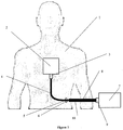
- a first preferred embodiment of this invention is shown in Figure 1 .
- a patient 1 is implanted with a medical assist device 2 to assist or enhance the patient's body function.
- this medical assist device may be active or passive and may require uni- or bi-directional data, instructions, and/or power in the form of electrical signals from the external environment.
- these electrical signals may be communicated by an external controller 7.
- an external controller 7 it may be preferable to use this embodiment in conjunction with an implantable blood pump or a left ventricle assist device.
- the external controller 7 is in electrical communication with the implanted medical device 2 by the use of the flexible percutaneous lead assembly 10.
- the external controller 7 is or may include any of the following devices: batteries, power supply, hardware controller, personal computer, microcontroller, and/or microprocessors.
- the connection formed by the percutaneous lead assembly 10 may allow for the transmission and reception of electrical signals.
- the lead assembly 10 may allow for a continuous electrical link between the medical device 2 and the controlling device 7 by the use of continuous wiring (not shown in Figure 1 ) running through the core of the lead assembly 10.
- the lead assembly 10 extends from the medical device 2, implanted within the body of the patient 1, through a hole or aperture 5, made by a physician or doctor, to the controlling device 7.
- the preferred percutaneous lead assembly 10 may also include: two ends, two connectors 3 & 9, wherein one connecter is connected to either end of the lead assembly 10 and wherein preferably each connector 3 & 9 is designed to mate with a respective corresponding connector on the medical device 2 and/or the controlling device 7.
- the percutaneous lead assembly 10 has a first portion 8 and a second portion 4.
- the second portion 4 may extend from the first connector 3 through the aperture 5 and join with the first portion 8.
- the section of the lead referred to as the second portion 4 may include regions coated with a textured surface. This textured surface may be produced by coating the region of the lead with velour or DacronTM. These types of coating materials promote ingrowth of the patient's cells into the surface of the textured surface and assist in anchoring lead assembly 10 within the patient's body 1. It is also preferred to only coat the lead portions, where necessary to achieve the desired amount of ingrowth or anchoring within the body 1.
- the second portion 4 extends out from the patient's body 1 through the hole 5. This extension past the hole 5 is shown by relatively thin region 6. Preferably, region 6 does not include a textured coating. Please note that hole 5 may also be referred to as a permanent exit wound.
- the relatively thin region 6 is integrally joined to the relatively thick region of first portion 8.
- the first portion 8 is also joined to a connector 9.
- the connector 9 may be connected to a controlling device 7.
- the second portion 4 passing through the exit wound 5 generally allows the exit wound to be of a substantially smaller diameter than otherwise would be the case if the lead assembly was of a uniform thickness. This reduction in the size of the exit wound may lessen the trauma experienced by patient 1 during and after implantation; as well as reducing the chance of infection at or near to the exit wound region.
- the relatively thick region of first portion 8 of the lead assembly 10 may allow for increased wear resistance of the external portion of the lead as well as providing extra shielding for the wiring within the assembly 10.
- first portion 8 may be constructed by wrapping or coating the relatively thin regions that extend externally from the patient's body and effectively protect or reinforce the external portion of the lead assembly 10. Additionally, a protective sheath may be used with the first portion 8 to achieve a similar effect of protecting the external portion of the wiring assembly.
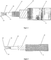
- a preferred embodiment shown in Figure 2 depicts a cross sectional cut away view of the first portion 8 of lead assembly 10.
- the first portion 8 of the lead assembly 10 may include: an outer protective sheath 11, an inner protective sheath 12, an electromagnetic shielding layer 13, and a wire bundle 14.
- the outer protective sheath 11 is constructed from a tough but flexible material that is preferably wear resistant and/or cut resistant.
- the outer protective sheath 11 may be constructed of polyurethane material.
- the materials used to construct the first portion 8 of the lead assembly do not need to be biocompatible and may even be toxic during implant conditions. This is because the first portion 8 is preferably not implanted within the body of the patient.
- the inner protective sheath 12 provides additional wear resistance.
- the inner protective sheath 12 may function to support the general shape and configuration of the first portion 8.
- the inner protective sheath 12 is flexible yet resistant to wear.
- the inner protective sheath 12 may be constructed of silicone rubber or a similar polymer known as NusilTM. Silicone and NusilTM also have the advantage that they are relatively transparent and enable easy inspection as to the condition and quality of the inner protective sheath 12.
- the electromagnetic shielding layer 13 is included within the structure of the first portion 8 of the lead assembly. This layer may function to prevent electromagnetic interference from the outside environment interfering with the electric signals being communicated by the lead assembly, when in use.
- the electromagnetic shielding layer 13 is preferably constructed from braided stainless steel and this is because metals generally provide the most efficient electromagnetic shielding. Additionally, stainless steel braid is relatively wear resistant and cut resistant, which prevents accidental breakage by a patient, user or doctor. Also, stainless steel is generally resistant to oxidation or rusting and is therefore preferred for long term applications in vigorous environments and is also suitable for implantation.
- a wire bundle 14 which contains the wires to act as an electrical conduit for the lead assembly.
- the wire bundle is generally assembled by inter weaving several insulated wires 15 with each other and a wiring strain relief 17. The position of the wires and the mechanical strain relief set in place using second layer of silicone or NusilTM.
- the lead assembly 10 includes three wires, but any number of wires are possible. An increase in the number of wires will increase the overall minimum diameter of the lead assembly, therefore it is preferred to include a minimum amount of insulated wires to provide functionality to the implantable medical device for which the lead assembly is to cooperate.
- the wiring strain relief 17 is constructed from 2 KevlarTM cords with a combined approximate breaking strain of 630N. Additionally, the wires 16 within the wire bundle 14 should be separately insulated preferably using Perfluoroalyoxy ('PFA') insulation 15.
- 'PFA' Perfluoroalyoxy
- FIG. 3 depicts the second portion 4 of the lead assembly 10.
- the second portion 4 may include a textured outer surface 19, outer protective layer 21, and a wire bundle 22.
- a segment of second portion 4 is covered with a textured outer surface 19,
- the textured outer surface 19 may be constructed of velour or DacronTM. This textured surface may permit a patient's body to ingrow into regions of the lead assembly covered with this textured surface 19. It may also be noted that the textured surface preferably only coats regions of the lead assembly which necessarily must be anchored to the patient's body. Portions of the relatively thin region 6 which extends externally from the patient's body may not require a textured surface for this reason.
- the outer protective layer 21 adds further wear resistance, maybe flexible, maybe substantially biocompatible and maybe suitable for implantation.
- the outer protective layer 21 may be constructed of silicone or NusilTM.
- Beneath the outer protective layer 21 preferably is a wire bundle 22.
- This wire bundle 22 may include: three wires 25 (which are insulated preferably by PFA 23), a wiring strain relief 24, and some silicone or NusilTM to provide dimensional support.
- the wire bundle 22 may be constructed in similar manner to the wire bundle 14 depicted in Figure 2 .
- the smaller or thinner diameter of second portion 4 may also increase the anchoring effect of the textured surface, as the thinner region may allow for better tissue integration.
- the smaller or thinner diameter may be accomplished by the removal of outer protective sheath 1 1 and the shielding layer 13.
- the shielding layer 13 may not be required for communicating electrical signals with a medical device, particularly in cases where the length of the relatively thin region of the lead assembly is relatively short when compared against the exposed regions of the lead assembly 10 which are external to the patient, such as the first portion 8.
- FIG. 4 A further embodiment is shown in Figure 4 , wherein the lead assembly 10 is implanted within a patient. Please note that similar numerical labelling to Figure 1 has been used in relation to Figure 4 .
- the skin layer 26 of a patient is shown with a hole, aperture or exit wound 5.
- the lead assembly 10 passes through the hole 5.
- This embodiment depicts the lead assembly 10 including a relatively thin region 6 and the thicker first portion 8 external of the body of the patient. Wires 30 pass through the centre of the lead assembly and allow electrical communication to be achieved between an external device and an internally implanted medical device.
- the internal portion of the lead assembly includes the relatively thin region 6 coated with a textured surface 4.
- the size of the hole 5 is minimised because of the thickness of the relatively thin region 6. This minimisation reduces the probability of infection and promotes wound healing by the patient's body.
- FIG. 5 A further embodiment is shown in Figure 5 .
- the lead assembly 10 includes a strain terminator mechanism.
- Figure 5 which uses similar numerical referencing as Figure 1 & 4 , shows the external surface of the patient's skin 26 at a site where the lead assembly 10 exits the body.
- the lead assembly in this embodiment includes a relatively thin region 6 and a first portion 8, joined by two connectors 33 & 34. These connectors mate to form a connection and allow electrical communication of the wires within the lead assembly.
- connectors 33 and 34 are submersible and/or water resistance. This water resistance feature will allow the patient to bath, shower or swim in relative safety in regard to medical device failure or electrocution. This may be achieved by including two 'O' rings within the connectors so as to provide a relatively good seal against water penetration.
- the connectors preferably are made of wear resistance plastic material which is lightweight and unlikely to cause discomfort to the patient. It may also be preferable to allow the connectors to be secured together, when in use, by a screw & thread means.
- the connectors 33 & 34 may also be preferable for the connectors 33 & 34 to allow for easy replacement of the first portion 8, in situations of accidental breakage without requiring the patient to undergo substantive invasive surgery. This may be achieved by disconnecting the connectors 33 & 34 and then attaching a replacement first portion 8 of the lead assembly.
- the strain terminator mechanism includes: a loop of redundant lead 37 and a lead restraint 35.
- the loop 37 is formed from the relatively thin region 6 of the lead assembly 10 extending from the hole 5 in the patient's skin layer.
- the strain relief mechanism is arranged so that if the lead assembly is accidentally or otherwise pulled, the lead assembly is not pulled from the patient's body. Obviously, if the lead assembly was pulled or jerked suddenly the net result may be to cause serious damage to the patient's skin layer and or internal organs. Additionally, the implanted medical device, which the lead assembly is connected internally to, may also be damaged by such an accident or incident.
- the lead restraint 35 would function to dampen the stresses otherwise experienced by hole 5.
- the lead restraint 35 preferably holds the lead assembly and may at the user's discretion release the lead assembly.
- the loop 37 of lead assembly functions to supply additional lead if the lead is pulled through the lead restraint 35.
- the loop 37 serves a backup and provides slack to the lead assembly between the hole 5 and lead restraint 35.
- any redundant lead length (such as a coil of lead) between the lead restraint 35 and the hole 5 will serve a similar function.
- the loop formation of the redundant length of lead is generally preferable for presentation or aesthetic reasons.
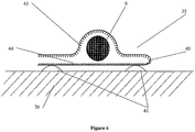
- FIG. 6 depicts a preferred lead restraint 35.
- This preferred lead restraint 35 includes: a flexible strip 40, interlocking VelcroTM segments 43 & 44 and adhesive 41.
- the lead restraint 35 is constructed by gluing a portion of the flexible strip 40 to the surface skin layer 26 of a patient. This may be accomplished by applying adhesive 41 to the locations depicted in Figure 6 . Attached to the opposed surface of flexible strip 40, which was glued to the patient's skin, may be attached at least two segments of interlocking and complementary VelcroTM 43 & 44 regions. This arrangement preferably allows the flexible strip 40 to fold and allow the complementary VecroTM 43 & 44 regions to interlock and/or connect.
- the relatively thin region 6 of the lead assembly 10 is positioned between the two interlocking layers of VelcroTM 43 & 44.
- the relatively thin region 6 may be secured in place by the lead restraint 35.
- the interlocking regions 43 & 44 secure the relatively thin region 6 firmly enough so as to restrain the lead from accidental stress induced by pulling or stretching.
- the lead restraint 35 may be positioned to also restrain the first portion 8.
- a percutaneous lead assembly for supplying electrical signals to a medical device implanted within a body of a patient, said lead assembly comprising a flexible elongate member having a first portion adapted to remain external to the body of a patient, said first portion having a first diameter; and a second portion joined to said first portion and adapted to extend through a hole in a skin layer of the body of the patient, and wherein said second portion having a second diameter which is substantially smaller than said first diameter.
- the first portion includes a shielding layer and/or at least a segment of said second portion is covered with a textured surface.
- the first portion and said second portion are joined by connectors.
- the percutaneous lead assembly may include a lead restraint.
- an external lead restraint for use with a percutaneous lead, wherein said lead is implanted within a body of a patient and extends through a hole in the patient's skin and characterised in that an excess length of lead is releasably secured near to the hole by releasable securing means affixed to the patient's skin.
- a percutaneous lead assembly for supplying electrical signal to a medical device implanted within a body of a patient, wherein said lead assembly has a flexible elongate member including a first unshielded portion that extends through a hole in a skin layer of the body of the patient; and a second shielded portion which is joined to said first unshielded portion at a site external to the body of the patient.
Landscapes
- Health & Medical Sciences (AREA)
- Cardiology (AREA)
- Heart & Thoracic Surgery (AREA)
- Engineering & Computer Science (AREA)
- Biomedical Technology (AREA)
- Nuclear Medicine, Radiotherapy & Molecular Imaging (AREA)
- Radiology & Medical Imaging (AREA)
- Life Sciences & Earth Sciences (AREA)
- Animal Behavior & Ethology (AREA)
- General Health & Medical Sciences (AREA)
- Public Health (AREA)
- Veterinary Medicine (AREA)
- Electrotherapy Devices (AREA)
Claims (8)
- Un ensemble conducteur percutané pour fournir des signaux électriques à un dispositif médical implanté dans un corps d'un patient, ledit ensemble conducteur comprenant
un élément allongé flexible ayantune première partie (8) adaptée pour rester hors du corps d'un patient etune seconde partie (4) reliée à ladite première partie (8) ;dans lequel la première partie (8) et la seconde partie (4) incluent des connecteurs respectifs premier (34) et second (33) adaptés pour s'accoupler et permettre une communication électrique dans l'ensemble conducteur percutané (10),dans lequel la première partie (8) a un premier diamètre et la seconde partie (4) a un second diamètre qui est essentiellement plus petit que le premier diamètre ;dans lequel un segment de la seconde partie (4) est recouvert avec une surface texturée (19), etdans lequel la seconde partie (4) inclut une partie non protégée qui s'étend à travers une ouverture (5) dans une couche de la peau (26) du corps du patient ; et la première partie (8) inclut une partie protégée qui est reliée à la partie non protégée dans un endroit extérieure au corps du patient lorsque les connecteurs (33, 34) sont accouplés. - L'ensemble conducteur percutané tel que revendiqué dans la revendication 1, dans lequel les connecteurs permettent en outre d'enlever la première partie (8) de la seconde partie (4).
- L'ensemble conducteur percutané tel que revendiqué dans la revendication 1, dans lequel l'ensemble conducteur percutané (10) inclut un dispositif de retenue du conducteur (35).
- L'ensemble conducteur percutané tel que revendiqué dans la revendication 3, dans lequel, lorsque la seconde partie (4) est implantée dans le corps du patient et la partie non protégée s'étend à travers l'ouverture (5) dans la peau du patient (26), une longueur en excès (37) du conducteur est attachée de façon amovible près de l'ouverture (5) moyennant un moyen d'attache amovible fixé à la peau du patient.
- L'ensemble conducteur percutané tel que revendiqué dans la revendication 2, dans lequel les connecteurs premier (34) et second (33) sont accouplés avec un moyen de vissage et enfilage.
- L'ensemble conducteur percutané tel que revendiqué dans la revendication 5, dans lequel des juntes toriques sont incluses dans les connecteurs premier (33) et second (34) afin de les faire submersibles ou résistants à l'eau.
- L'ensemble conducteur percutané tel que revendiqué dans la revendication 1, dans lequel un faisceau de fils (14, 22) comprenant trois fils isolés (15, 25) et un moyen de soulagement de tension de fils (17, 24) sont contenus dans l'ensemble conducteur percutané (10).
- L'ensemble conducteur percutané tel que revendiqué dans l'une quelconque des revendications précédentes, dans lequel la surface texturée (19) est un revêtement de velours ou de dacron.
Applications Claiming Priority (3)
| Application Number | Priority Date | Filing Date | Title |
|---|---|---|---|
| AU2004900538A AU2004900538A0 (en) | 2004-02-04 | An Improved Percutaneous Lead | |
| PCT/AU2005/000135 WO2005075017A1 (fr) | 2004-02-04 | 2005-02-02 | Conducteur percutane ameliore |
| EP05700165.3A EP1711221B1 (fr) | 2004-02-04 | 2005-02-02 | Conducteur percutane ameliore |
Related Parent Applications (2)
| Application Number | Title | Priority Date | Filing Date |
|---|---|---|---|
| EP05700165.3A Division EP1711221B1 (fr) | 2004-02-04 | 2005-02-02 | Conducteur percutane ameliore |
| EP05700165.3A Division-Into EP1711221B1 (fr) | 2004-02-04 | 2005-02-02 | Conducteur percutane ameliore |
Publications (2)
| Publication Number | Publication Date |
|---|---|
| EP2505228A1 EP2505228A1 (fr) | 2012-10-03 |
| EP2505228B1 true EP2505228B1 (fr) | 2018-11-21 |
Family
ID=34831679
Family Applications (2)
| Application Number | Title | Priority Date | Filing Date |
|---|---|---|---|
| EP05700165.3A Expired - Lifetime EP1711221B1 (fr) | 2004-02-04 | 2005-02-02 | Conducteur percutane ameliore |
| EP12162608.9A Expired - Lifetime EP2505228B1 (fr) | 2004-02-04 | 2005-02-02 | Electrode-sonde percutanée améliorée |
Family Applications Before (1)
| Application Number | Title | Priority Date | Filing Date |
|---|---|---|---|
| EP05700165.3A Expired - Lifetime EP1711221B1 (fr) | 2004-02-04 | 2005-02-02 | Conducteur percutane ameliore |
Country Status (5)
| Country | Link |
|---|---|
| US (1) | US20070129779A1 (fr) |
| EP (2) | EP1711221B1 (fr) |
| JP (1) | JP4839224B2 (fr) |
| CA (2) | CA2800131A1 (fr) |
| WO (1) | WO2005075017A1 (fr) |
Families Citing this family (31)
| Publication number | Priority date | Publication date | Assignee | Title |
|---|---|---|---|---|
| US7844344B2 (en) | 2004-03-30 | 2010-11-30 | Medtronic, Inc. | MRI-safe implantable lead |
| US8152035B2 (en) * | 2005-07-12 | 2012-04-10 | Thoratec Corporation | Restraining device for a percutaneous lead assembly |
| JP5155186B2 (ja) | 2006-01-13 | 2013-02-27 | ハートウェア、インコーポレイテッド | 回転式血液ポンプ |
| US9044593B2 (en) | 2007-02-14 | 2015-06-02 | Medtronic, Inc. | Discontinuous conductive filler polymer-matrix composites for electromagnetic shielding |
| US8483842B2 (en) | 2007-04-25 | 2013-07-09 | Medtronic, Inc. | Lead or lead extension having a conductive body and conductive body contact |
| US9037263B2 (en) | 2008-03-12 | 2015-05-19 | Medtronic, Inc. | System and method for implantable medical device lead shielding |
| US9205253B2 (en) | 2009-04-30 | 2015-12-08 | Medtronic, Inc. | Shielding an implantable medical lead |
| US8562508B2 (en) | 2009-12-30 | 2013-10-22 | Thoratec Corporation | Mobility-enhancing blood pump system |
| EP2519274B1 (fr) * | 2009-12-30 | 2016-04-20 | Thoratec Corporation | Système de pompe à sang à amélioration de la mobilité |
| WO2011156391A2 (fr) | 2010-06-07 | 2011-12-15 | Thoratec Corporation | Câble percutané bi-ventriculaire |
| TW201225997A (en) | 2010-08-20 | 2012-07-01 | Thoratec Corp | Assembly and method for stabilizing a percutaneous cable |
| CN103338812A (zh) * | 2010-12-02 | 2013-10-02 | Med-El电气医疗器械有限公司 | 用于生物医疗植入物和电极的表面涂层 |
| EP2838609B1 (fr) | 2012-04-19 | 2019-03-06 | Medtronic, Inc. | Corps de conducteurs appariés à usage médical comportant des blindages conducteurs tressés ayant des valeurs de paramètres physiques différentes |
| EP2868345A1 (fr) * | 2013-10-31 | 2015-05-06 | Berlin Heart GmbH | Agencement électrique comprenant un élément de câble pouvant être implanté |
| US9993638B2 (en) | 2013-12-14 | 2018-06-12 | Medtronic, Inc. | Devices, systems and methods to reduce coupling of a shield and a conductor within an implantable medical lead |
| US9700714B2 (en) | 2013-12-20 | 2017-07-11 | Medtronic, Inc. | Methods and devices for inhibiting tissue growth from restricting a strain relief loop of an implantable medical lead |
| WO2016014427A1 (fr) | 2014-07-23 | 2016-01-28 | Medtronic, Inc. | Procédés de protection de dérivations médicales implantables et d'extension de dérivation médicale implantable |
| WO2016014816A1 (fr) | 2014-07-24 | 2016-01-28 | Medtronic, Inc. | Procédés de blindage de sondes médicales implantables et d'extensions de sondes médicales implantables |
| EP3634528B1 (fr) | 2017-06-07 | 2023-06-07 | Shifamed Holdings, LLC | Dispositifs de déplacement de fluide intravasculaire, systèmes et procédés d'utilisation |
| US11511103B2 (en) | 2017-11-13 | 2022-11-29 | Shifamed Holdings, Llc | Intravascular fluid movement devices, systems, and methods of use |
| EP3746149B1 (fr) | 2018-02-01 | 2025-08-06 | Shifamed Holdings, LLC | Pompes à sang intravasculaires |
| WO2020028537A1 (fr) | 2018-07-31 | 2020-02-06 | Shifamed Holdings, Llc | Pompes sanguines intravasculaires et procédés d'utilisation |
| WO2020073047A1 (fr) | 2018-10-05 | 2020-04-09 | Shifamed Holdings, Llc | Pompes à sang intravasculaires et procédés d'utilisation |
| WO2021011473A1 (fr) | 2019-07-12 | 2021-01-21 | Shifamed Holdings, Llc | Pompes à sang intravasculaires et méthode d'utilisation et procédé de fabrication |
| US11654275B2 (en) | 2019-07-22 | 2023-05-23 | Shifamed Holdings, Llc | Intravascular blood pumps with struts and methods of use and manufacture |
| US12465748B2 (en) | 2019-08-07 | 2025-11-11 | Supira Medical, Inc. | Catheter blood pumps and collapsible pump housings |
| WO2021062260A1 (fr) | 2019-09-25 | 2021-04-01 | Shifamed Holdings, Llc | Pompes à sang de cathéter et conduits sanguins pliables |
| US11724089B2 (en) | 2019-09-25 | 2023-08-15 | Shifamed Holdings, Llc | Intravascular blood pump systems and methods of use and control thereof |
| EP4501393A3 (fr) | 2019-09-25 | 2025-04-09 | Shifamed Holdings, LLC | Pompes à sang à cathéter et boîtiers de pompes pliables |
| EP4072650A4 (fr) | 2019-12-11 | 2024-01-10 | Shifamed Holdings, LLC | Pompes à sang d'aorte descendante et de veine cave |
| EP4077947A4 (fr) | 2019-12-19 | 2024-01-10 | Shifamed Holdings, LLC | Pompes à sang intravasculaires, moteurs et commande de fluide |
Citations (4)
| Publication number | Priority date | Publication date | Assignee | Title |
|---|---|---|---|---|
| US3699956A (en) * | 1970-10-01 | 1972-10-24 | Tecna Corp | Percutaneous lead device |
| WO1995017026A1 (fr) * | 1993-12-14 | 1995-06-22 | Laser Engineering, Inc. | Ensemble conducteur/aiguille-electrode pour moniteur d'electrocardiographie |
| US20020058978A1 (en) * | 1999-10-08 | 2002-05-16 | Sass Richard G. | Cardiac implant cable having a coaxial lead |
| WO2002094348A1 (fr) * | 2001-05-21 | 2002-11-28 | Ventrassist Pty Ltd | Implantation par etapes d'appareils d'assistance ventriculaire |
Family Cites Families (19)
| Publication number | Priority date | Publication date | Assignee | Title |
|---|---|---|---|---|
| US4041936A (en) * | 1975-04-23 | 1977-08-16 | Medical Engineering Corporation | Bronchoscopy tube |
| US5144848A (en) * | 1989-11-27 | 1992-09-08 | Olympus Optical Co., Ltd. | Intra-tube traveling apparatus |
| US5246014A (en) * | 1991-11-08 | 1993-09-21 | Medtronic, Inc. | Implantable lead system |
| US5931850A (en) * | 1992-08-03 | 1999-08-03 | Zadini; Filiberto P. | (Percutaneous cardiac pump for cardiopulmonary resuscitation) cardiac resuscitation device for percutaneous direct cardiac massage |
| US5376108A (en) * | 1993-05-20 | 1994-12-27 | Telectronics Pacing Systems, Inc. | Electrode lead anchoring apparatus and method employing dual suture collars |
| US5527358A (en) * | 1994-01-21 | 1996-06-18 | Medtronic, Inc. | Temporary medical electrical lead |
| US6285910B1 (en) * | 1997-04-21 | 2001-09-04 | Medtronic, Inc. | Medical electrical lead |
| US5796044A (en) * | 1997-02-10 | 1998-08-18 | Medtronic, Inc. | Coiled wire conductor insulation for biomedical lead |
| JPH10309321A (ja) * | 1997-03-11 | 1998-11-24 | San Medical Gijutsu Kenkyusho:Kk | 皮膚ボタン |
| US6324415B1 (en) * | 1997-07-30 | 2001-11-27 | Intermedics Inc. | Cardiac lead with minimized inside diameter of sleeve |
| US5904646A (en) * | 1997-09-08 | 1999-05-18 | Jarvik; Robert | Infection resistant power cable system for medically implanted electric motors |
| US7887477B2 (en) * | 1999-08-09 | 2011-02-15 | Cardiokinetix, Inc. | Method of improving cardiac function using a porous membrane |
| US6542781B1 (en) * | 1999-11-22 | 2003-04-01 | Scimed Life Systems, Inc. | Loop structures for supporting diagnostic and therapeutic elements in contact with body tissue |
| US6606522B2 (en) * | 2001-05-30 | 2003-08-12 | Cardiac Pacemakers, Inc. | Torque mechanism and method for endocardial leads |
| US20030028148A1 (en) * | 2001-08-01 | 2003-02-06 | Welcon, Inc. | Tubing holder and stabilizer |
| US20030144718A1 (en) * | 2002-01-29 | 2003-07-31 | Zeijlemaker Volkert A. | Method and apparatus for shielding coating for MRI resistant electrode systems |
| US7158837B2 (en) * | 2002-07-10 | 2007-01-02 | Oscor Inc. | Low profile cardiac leads |
| US7158838B2 (en) * | 2003-01-31 | 2007-01-02 | Medtronic, Inc. | Arrangement for implanting a miniaturized cardiac lead having a fixation helix |
| EP1613252B1 (fr) * | 2003-04-12 | 2016-03-09 | IncuMed LLC | Dispositif médical implantable par voie percutanée destiné à favoriser la croissance interne du tissu |
-
2005
- 2005-02-02 US US10/588,171 patent/US20070129779A1/en not_active Abandoned
- 2005-02-02 WO PCT/AU2005/000135 patent/WO2005075017A1/fr not_active Ceased
- 2005-02-02 JP JP2006551679A patent/JP4839224B2/ja not_active Expired - Fee Related
- 2005-02-02 EP EP05700165.3A patent/EP1711221B1/fr not_active Expired - Lifetime
- 2005-02-02 CA CA2800131A patent/CA2800131A1/fr not_active Abandoned
- 2005-02-02 EP EP12162608.9A patent/EP2505228B1/fr not_active Expired - Lifetime
- 2005-02-02 CA CA2556035A patent/CA2556035C/fr not_active Expired - Fee Related
Patent Citations (4)
| Publication number | Priority date | Publication date | Assignee | Title |
|---|---|---|---|---|
| US3699956A (en) * | 1970-10-01 | 1972-10-24 | Tecna Corp | Percutaneous lead device |
| WO1995017026A1 (fr) * | 1993-12-14 | 1995-06-22 | Laser Engineering, Inc. | Ensemble conducteur/aiguille-electrode pour moniteur d'electrocardiographie |
| US20020058978A1 (en) * | 1999-10-08 | 2002-05-16 | Sass Richard G. | Cardiac implant cable having a coaxial lead |
| WO2002094348A1 (fr) * | 2001-05-21 | 2002-11-28 | Ventrassist Pty Ltd | Implantation par etapes d'appareils d'assistance ventriculaire |
Also Published As
| Publication number | Publication date |
|---|---|
| EP2505228A1 (fr) | 2012-10-03 |
| JP2007520283A (ja) | 2007-07-26 |
| WO2005075017A1 (fr) | 2005-08-18 |
| EP1711221A1 (fr) | 2006-10-18 |
| EP1711221B1 (fr) | 2019-09-18 |
| EP1711221A4 (fr) | 2010-01-13 |
| CA2556035C (fr) | 2013-04-02 |
| JP4839224B2 (ja) | 2011-12-21 |
| CA2800131A1 (fr) | 2005-08-18 |
| US20070129779A1 (en) | 2007-06-07 |
| CA2556035A1 (fr) | 2005-08-18 |
Similar Documents
| Publication | Publication Date | Title |
|---|---|---|
| CA2556035C (fr) | Conducteur percutane ameliore | |
| US20110152600A1 (en) | Implantable heart assist system | |
| EP2164538B1 (fr) | Vad implantable avec câble percutané remplaçable | |
| US5904646A (en) | Infection resistant power cable system for medically implanted electric motors | |
| US8099175B2 (en) | Medical electrical lead with proximal armoring | |
| AU2004260554B2 (en) | Improved transcutaneous power and/or data transceiver system | |
| WO2008106717A1 (fr) | Système transcutané de transfert d'énergie | |
| CA2323769A1 (fr) | Connecteur pour dispositif medical implantable | |
| TW201230524A (en) | Bi-ventricular percutaneous cable | |
| US20210170083A1 (en) | Implantable medical device including cable fastener | |
| AU2009357383A1 (en) | Mobility-enhancing blood pump system | |
| US20090281409A1 (en) | Reinforced medical device | |
| AU2005209946B2 (en) | An improved percutaneous lead | |
| US11439813B2 (en) | Percutaneous lead | |
| US20240171009A1 (en) | Transformer implant for inductive power supply to implanted medical device | |
| EP4008396B1 (fr) | Système de fixation pour un générateur de stimulation électrique | |
| US20210290940A1 (en) | Lvad fixation and infection management |
Legal Events
| Date | Code | Title | Description |
|---|---|---|---|
| PUAI | Public reference made under article 153(3) epc to a published international application that has entered the european phase |
Free format text: ORIGINAL CODE: 0009012 |
|
| AC | Divisional application: reference to earlier application |
Ref document number: 1711221 Country of ref document: EP Kind code of ref document: P |
|
| AK | Designated contracting states |
Kind code of ref document: A1 Designated state(s): AT BE BG CH CY CZ DE DK EE ES FI FR GB GR HU IE IS IT LI LT LU MC NL PL PT RO SE SI SK TR |
|
| RIN1 | Information on inventor provided before grant (corrected) |
Inventor name: WOODARD, JOHN CAMPBELL Inventor name: BEGG, JOHN DONALD Inventor name: AYRE, PETER JOSEPH |
|
| 17P | Request for examination filed |
Effective date: 20130403 |
|
| STAA | Information on the status of an ep patent application or granted ep patent |
Free format text: STATUS: EXAMINATION IS IN PROGRESS |
|
| 17Q | First examination report despatched |
Effective date: 20170221 |
|
| GRAP | Despatch of communication of intention to grant a patent |
Free format text: ORIGINAL CODE: EPIDOSNIGR1 |
|
| STAA | Information on the status of an ep patent application or granted ep patent |
Free format text: STATUS: GRANT OF PATENT IS INTENDED |
|
| RAP1 | Party data changed (applicant data changed or rights of an application transferred) |
Owner name: TC1 LLC |
|
| INTG | Intention to grant announced |
Effective date: 20180530 |
|
| GRAS | Grant fee paid |
Free format text: ORIGINAL CODE: EPIDOSNIGR3 |
|
| GRAA | (expected) grant |
Free format text: ORIGINAL CODE: 0009210 |
|
| STAA | Information on the status of an ep patent application or granted ep patent |
Free format text: STATUS: THE PATENT HAS BEEN GRANTED |
|
| AC | Divisional application: reference to earlier application |
Ref document number: 1711221 Country of ref document: EP Kind code of ref document: P |
|
| AK | Designated contracting states |
Kind code of ref document: B1 Designated state(s): AT BE BG CH CY CZ DE DK EE ES FI FR GB GR HU IE IS IT LI LT LU MC NL PL PT RO SE SI SK TR |
|
| REG | Reference to a national code |
Ref country code: CH Ref legal event code: EP |
|
| REG | Reference to a national code |
Ref country code: IE Ref legal event code: FG4D |
|
| REG | Reference to a national code |
Ref country code: AT Ref legal event code: REF Ref document number: 1066849 Country of ref document: AT Kind code of ref document: T Effective date: 20181215 |
|
| REG | Reference to a national code |
Ref country code: DE Ref legal event code: R096 Ref document number: 602005055040 Country of ref document: DE |
|
| PGFP | Annual fee paid to national office [announced via postgrant information from national office to epo] |
Ref country code: ES Payment date: 20181203 Year of fee payment: 8 |
|
| REG | Reference to a national code |
Ref country code: NL Ref legal event code: MP Effective date: 20181121 |
|
| REG | Reference to a national code |
Ref country code: AT Ref legal event code: MK05 Ref document number: 1066849 Country of ref document: AT Kind code of ref document: T Effective date: 20181121 |
|
| PG25 | Lapsed in a contracting state [announced via postgrant information from national office to epo] |
Ref country code: BG Free format text: LAPSE BECAUSE OF FAILURE TO SUBMIT A TRANSLATION OF THE DESCRIPTION OR TO PAY THE FEE WITHIN THE PRESCRIBED TIME-LIMIT Effective date: 20190221 Ref country code: FI Free format text: LAPSE BECAUSE OF FAILURE TO SUBMIT A TRANSLATION OF THE DESCRIPTION OR TO PAY THE FEE WITHIN THE PRESCRIBED TIME-LIMIT Effective date: 20181121 Ref country code: LT Free format text: LAPSE BECAUSE OF FAILURE TO SUBMIT A TRANSLATION OF THE DESCRIPTION OR TO PAY THE FEE WITHIN THE PRESCRIBED TIME-LIMIT Effective date: 20181121 Ref country code: ES Free format text: LAPSE BECAUSE OF FAILURE TO SUBMIT A TRANSLATION OF THE DESCRIPTION OR TO PAY THE FEE WITHIN THE PRESCRIBED TIME-LIMIT Effective date: 20181121 Ref country code: AT Free format text: LAPSE BECAUSE OF FAILURE TO SUBMIT A TRANSLATION OF THE DESCRIPTION OR TO PAY THE FEE WITHIN THE PRESCRIBED TIME-LIMIT Effective date: 20181121 Ref country code: IS Free format text: LAPSE BECAUSE OF FAILURE TO SUBMIT A TRANSLATION OF THE DESCRIPTION OR TO PAY THE FEE WITHIN THE PRESCRIBED TIME-LIMIT Effective date: 20190321 |
|
| PG25 | Lapsed in a contracting state [announced via postgrant information from national office to epo] |
Ref country code: PT Free format text: LAPSE BECAUSE OF FAILURE TO SUBMIT A TRANSLATION OF THE DESCRIPTION OR TO PAY THE FEE WITHIN THE PRESCRIBED TIME-LIMIT Effective date: 20190321 Ref country code: GR Free format text: LAPSE BECAUSE OF FAILURE TO SUBMIT A TRANSLATION OF THE DESCRIPTION OR TO PAY THE FEE WITHIN THE PRESCRIBED TIME-LIMIT Effective date: 20190222 Ref country code: NL Free format text: LAPSE BECAUSE OF FAILURE TO SUBMIT A TRANSLATION OF THE DESCRIPTION OR TO PAY THE FEE WITHIN THE PRESCRIBED TIME-LIMIT Effective date: 20181121 Ref country code: SE Free format text: LAPSE BECAUSE OF FAILURE TO SUBMIT A TRANSLATION OF THE DESCRIPTION OR TO PAY THE FEE WITHIN THE PRESCRIBED TIME-LIMIT Effective date: 20181121 |
|
| PG25 | Lapsed in a contracting state [announced via postgrant information from national office to epo] |
Ref country code: IT Free format text: LAPSE BECAUSE OF FAILURE TO SUBMIT A TRANSLATION OF THE DESCRIPTION OR TO PAY THE FEE WITHIN THE PRESCRIBED TIME-LIMIT Effective date: 20181121 Ref country code: CZ Free format text: LAPSE BECAUSE OF FAILURE TO SUBMIT A TRANSLATION OF THE DESCRIPTION OR TO PAY THE FEE WITHIN THE PRESCRIBED TIME-LIMIT Effective date: 20181121 Ref country code: DK Free format text: LAPSE BECAUSE OF FAILURE TO SUBMIT A TRANSLATION OF THE DESCRIPTION OR TO PAY THE FEE WITHIN THE PRESCRIBED TIME-LIMIT Effective date: 20181121 Ref country code: PL Free format text: LAPSE BECAUSE OF FAILURE TO SUBMIT A TRANSLATION OF THE DESCRIPTION OR TO PAY THE FEE WITHIN THE PRESCRIBED TIME-LIMIT Effective date: 20181121 |
|
| REG | Reference to a national code |
Ref country code: DE Ref legal event code: R097 Ref document number: 602005055040 Country of ref document: DE |
|
| PG25 | Lapsed in a contracting state [announced via postgrant information from national office to epo] |
Ref country code: SK Free format text: LAPSE BECAUSE OF FAILURE TO SUBMIT A TRANSLATION OF THE DESCRIPTION OR TO PAY THE FEE WITHIN THE PRESCRIBED TIME-LIMIT Effective date: 20181121 Ref country code: EE Free format text: LAPSE BECAUSE OF FAILURE TO SUBMIT A TRANSLATION OF THE DESCRIPTION OR TO PAY THE FEE WITHIN THE PRESCRIBED TIME-LIMIT Effective date: 20181121 Ref country code: RO Free format text: LAPSE BECAUSE OF FAILURE TO SUBMIT A TRANSLATION OF THE DESCRIPTION OR TO PAY THE FEE WITHIN THE PRESCRIBED TIME-LIMIT Effective date: 20181121 |
|
| PLBE | No opposition filed within time limit |
Free format text: ORIGINAL CODE: 0009261 |
|
| STAA | Information on the status of an ep patent application or granted ep patent |
Free format text: STATUS: NO OPPOSITION FILED WITHIN TIME LIMIT |
|
| REG | Reference to a national code |
Ref country code: CH Ref legal event code: PL |
|
| 26N | No opposition filed |
Effective date: 20190822 |
|
| PG25 | Lapsed in a contracting state [announced via postgrant information from national office to epo] |
Ref country code: MC Free format text: LAPSE BECAUSE OF FAILURE TO SUBMIT A TRANSLATION OF THE DESCRIPTION OR TO PAY THE FEE WITHIN THE PRESCRIBED TIME-LIMIT Effective date: 20181121 Ref country code: SI Free format text: LAPSE BECAUSE OF FAILURE TO SUBMIT A TRANSLATION OF THE DESCRIPTION OR TO PAY THE FEE WITHIN THE PRESCRIBED TIME-LIMIT Effective date: 20181121 Ref country code: LU Free format text: LAPSE BECAUSE OF NON-PAYMENT OF DUE FEES Effective date: 20190202 |
|
| REG | Reference to a national code |
Ref country code: BE Ref legal event code: MM Effective date: 20190228 |
|
| REG | Reference to a national code |
Ref country code: IE Ref legal event code: MM4A |
|
| PG25 | Lapsed in a contracting state [announced via postgrant information from national office to epo] |
Ref country code: LI Free format text: LAPSE BECAUSE OF NON-PAYMENT OF DUE FEES Effective date: 20190228 Ref country code: CH Free format text: LAPSE BECAUSE OF NON-PAYMENT OF DUE FEES Effective date: 20190228 |
|
| PG25 | Lapsed in a contracting state [announced via postgrant information from national office to epo] |
Ref country code: IE Free format text: LAPSE BECAUSE OF NON-PAYMENT OF DUE FEES Effective date: 20190202 |
|
| PG25 | Lapsed in a contracting state [announced via postgrant information from national office to epo] |
Ref country code: BE Free format text: LAPSE BECAUSE OF NON-PAYMENT OF DUE FEES Effective date: 20190228 |
|
| PG25 | Lapsed in a contracting state [announced via postgrant information from national office to epo] |
Ref country code: TR Free format text: LAPSE BECAUSE OF FAILURE TO SUBMIT A TRANSLATION OF THE DESCRIPTION OR TO PAY THE FEE WITHIN THE PRESCRIBED TIME-LIMIT Effective date: 20181121 |
|
| PG25 | Lapsed in a contracting state [announced via postgrant information from national office to epo] |
Ref country code: FR Free format text: LAPSE BECAUSE OF NON-PAYMENT OF DUE FEES Effective date: 20200229 |
|
| PG25 | Lapsed in a contracting state [announced via postgrant information from national office to epo] |
Ref country code: CY Free format text: LAPSE BECAUSE OF FAILURE TO SUBMIT A TRANSLATION OF THE DESCRIPTION OR TO PAY THE FEE WITHIN THE PRESCRIBED TIME-LIMIT Effective date: 20181121 |
|
| PGFP | Annual fee paid to national office [announced via postgrant information from national office to epo] |
Ref country code: GB Payment date: 20210129 Year of fee payment: 17 Ref country code: DE Payment date: 20210113 Year of fee payment: 17 |
|
| PG25 | Lapsed in a contracting state [announced via postgrant information from national office to epo] |
Ref country code: HU Free format text: LAPSE BECAUSE OF FAILURE TO SUBMIT A TRANSLATION OF THE DESCRIPTION OR TO PAY THE FEE WITHIN THE PRESCRIBED TIME-LIMIT; INVALID AB INITIO Effective date: 20050202 |
|
| REG | Reference to a national code |
Ref country code: DE Ref legal event code: R119 Ref document number: 602005055040 Country of ref document: DE |
|
| GBPC | Gb: european patent ceased through non-payment of renewal fee |
Effective date: 20220202 |
|
| PG25 | Lapsed in a contracting state [announced via postgrant information from national office to epo] |
Ref country code: GB Free format text: LAPSE BECAUSE OF NON-PAYMENT OF DUE FEES Effective date: 20220202 Ref country code: DE Free format text: LAPSE BECAUSE OF NON-PAYMENT OF DUE FEES Effective date: 20220901 |