EP2505332A1 - Kunststoffkörper und Fertigungsanlage zur Herstellung eines Kunststoffkörpers - Google Patents
Kunststoffkörper und Fertigungsanlage zur Herstellung eines Kunststoffkörpers Download PDFInfo
- Publication number
- EP2505332A1 EP2505332A1 EP12001458A EP12001458A EP2505332A1 EP 2505332 A1 EP2505332 A1 EP 2505332A1 EP 12001458 A EP12001458 A EP 12001458A EP 12001458 A EP12001458 A EP 12001458A EP 2505332 A1 EP2505332 A1 EP 2505332A1
- Authority
- EP
- European Patent Office
- Prior art keywords
- diameter
- displacement
- cavity
- plastic
- displacement body
- Prior art date
- Legal status (The legal status is an assumption and is not a legal conclusion. Google has not performed a legal analysis and makes no representation as to the accuracy of the status listed.)
- Granted
Links
Images


Classifications
-
- B—PERFORMING OPERATIONS; TRANSPORTING
- B25—HAND TOOLS; PORTABLE POWER-DRIVEN TOOLS; MANIPULATORS
- B25F—COMBINATION OR MULTI-PURPOSE TOOLS NOT OTHERWISE PROVIDED FOR; DETAILS OR COMPONENTS OF PORTABLE POWER-DRIVEN TOOLS NOT PARTICULARLY RELATED TO THE OPERATIONS PERFORMED AND NOT OTHERWISE PROVIDED FOR
- B25F5/00—Details or components of portable power-driven tools not particularly related to the operations performed and not otherwise provided for
- B25F5/006—Vibration damping means
-
- B—PERFORMING OPERATIONS; TRANSPORTING
- B29—WORKING OF PLASTICS; WORKING OF SUBSTANCES IN A PLASTIC STATE IN GENERAL
- B29C—SHAPING OR JOINING OF PLASTICS; SHAPING OF MATERIAL IN A PLASTIC STATE, NOT OTHERWISE PROVIDED FOR; AFTER-TREATMENT OF THE SHAPED PRODUCTS, e.g. REPAIRING
- B29C45/00—Injection moulding, i.e. forcing the required volume of moulding material through a nozzle into a closed mould; Apparatus therefor
- B29C45/17—Component parts, details or accessories; Auxiliary operations
- B29C45/1703—Introducing an auxiliary fluid into the mould
- B29C45/1704—Introducing an auxiliary fluid into the mould the fluid being introduced into the interior of the injected material which is still in a molten state, e.g. for producing hollow articles
- B29C45/1711—Introducing an auxiliary fluid into the mould the fluid being introduced into the interior of the injected material which is still in a molten state, e.g. for producing hollow articles and removing excess material from the mould cavity by the introduced fluid, e.g. to an overflow cavity
-
- B—PERFORMING OPERATIONS; TRANSPORTING
- B27—WORKING OR PRESERVING WOOD OR SIMILAR MATERIAL; NAILING OR STAPLING MACHINES IN GENERAL
- B27B—SAWS FOR WOOD OR SIMILAR MATERIAL; COMPONENTS OR ACCESSORIES THEREFOR
- B27B17/00—Chain saws; Equipment therefor
- B27B17/0008—Means for carrying the chain saw, e.g. handles
-
- B—PERFORMING OPERATIONS; TRANSPORTING
- B29—WORKING OF PLASTICS; WORKING OF SUBSTANCES IN A PLASTIC STATE IN GENERAL
- B29C—SHAPING OR JOINING OF PLASTICS; SHAPING OF MATERIAL IN A PLASTIC STATE, NOT OTHERWISE PROVIDED FOR; AFTER-TREATMENT OF THE SHAPED PRODUCTS, e.g. REPAIRING
- B29C45/00—Injection moulding, i.e. forcing the required volume of moulding material through a nozzle into a closed mould; Apparatus therefor
- B29C2045/0087—Injection moulding, i.e. forcing the required volume of moulding material through a nozzle into a closed mould; Apparatus therefor making hollow articles using a floating core movable in the mould cavity by fluid pressure and expelling molten excess material
-
- Y—GENERAL TAGGING OF NEW TECHNOLOGICAL DEVELOPMENTS; GENERAL TAGGING OF CROSS-SECTIONAL TECHNOLOGIES SPANNING OVER SEVERAL SECTIONS OF THE IPC; TECHNICAL SUBJECTS COVERED BY FORMER USPC CROSS-REFERENCE ART COLLECTIONS [XRACs] AND DIGESTS
- Y10—TECHNICAL SUBJECTS COVERED BY FORMER USPC
- Y10T—TECHNICAL SUBJECTS COVERED BY FORMER US CLASSIFICATION
- Y10T428/00—Stock material or miscellaneous articles
- Y10T428/13—Hollow or container type article [e.g., tube, vase, etc.]
- Y10T428/1352—Polymer or resin containing [i.e., natural or synthetic]
Definitions
- the invention relates to a plastic body and a production plant for producing a plastic body.
- the invention has for its object to provide a plastic body which has a low weight, high stability and high dimensional stability. Another object of the invention is to provide a manufacturing plant for producing a plastic body with low weight, high stability and high dimensional accuracy.
- the plastic body is formed in its central region as a tubular hollow body, results in a high stability with low weight.
- the tubular hollow body is advantageously produced in a projectile injection method in which the displacement body has been pushed through the central region, namely by a fluid.
- the cavity formed at the second end of the tubular hollow body is not made by the displacement body, but only by the fluid.
- the cavity is produced in the production by holding the fluid pressure for a long time.
- the cavity is not made in a projectile internal pressure process, but in a fluid internal pressure process.
- the middle region can be arranged so that there are no excessive deflections and changes in direction for the displacement body during manufacture.
- the position in which the injector nozzle protrudes into the plastic body can be chosen so that the opening does not interfere, for example by positioning such that it is covered by other components or can be used as a fastening opening.
- the tubular hollow body has on its inner wall advantageously a very low roughness.
- the maximum profile height ie the distance between the line of the profile peaks and the profile valleys is advantageously less than 0.1 mm.
- the wall thickness is very low. In the region of the hollow body, the maximum profile height is greater by a multiple and is in particular more than 0.3 mm, in particular more than 0.5 mm.
- the wall thickness in this area is a multiple, advantageously about 2.5 times to about 5 times the wall thickness of the tubular hollow body.
- the displacement body has an opening for a Aufsteckabêt an injector.
- the displacement body can be placed in the preparation prior to the introduction of melt on the injector nozzle.
- the opening formed in the production can be kept small inside the plastic body.
- the tubular hollow body is in particular closed at one end and closed at the other end except for the opening formed by the injector nozzle.
- the opening in the displacement body is in particular conical, so that the displacement body can be firmly attached to the injector nozzle.
- the design of the displacement body is influenced by the scattering of the wall thickness of the plastic body.
- the displacement body has a cylindrical portion and a tapered portion, wherein the tapered portion projects into the solid body.
- the cylindrical section in particular forms the sections in which the plastic body extends straight, while the tapered section forms bends of the plastic body.
- the tapered portion is formed as a paraboloid or as a rotational body of a circular segment.
- the ratio of the height of the displacement body to the diameter in the cylindrical portion is advantageously from about 0.6 to about 2. A ratio of height to diameter of about 1.25 has proven particularly advantageous.
- the cylindrical portion is advantageously narrow.
- the height of the cylindrical portion is advantageously from about 0.1 to about 0.3, based on the diameter in the cylindrical portion.
- the diameter of the cylindrical portion corresponds to the largest diameter of the tapered portion.
- the displacement body has at least one stiffening rib on the side delimiting the hollow body.
- the plastic body has an injector opening.
- the ratio of the diameter of the injector opening to the diameter of the displacement body is advantageously less than about 0.7, in particular less than about 0.5, advantageously less than about 0.3. This results in a slight impairment of the ergonomics and the appearance of the plastic body through the injector opening with low weight of the plastic body.
- the displacement body which remains in the plastic body is advantageously used to form a gradual transition of stiffness from the hollow body to the first solid body. About the design and the material of the displacement body of this stiffness transition can be adjusted.
- the strength of the plastic body in the region of the displacement body is advantageously lower than in the region of the first solid body and greater than the strength of the hollow body. As a result, large jumps in stiffness in the transition from hollow body to solid body are avoided.
- the total length of the solid body is less than 50% of the length of the tubular hollow body.
- the plastic body is in particular a handle tube for a portable, hand-held implement.
- the injector nozzle has a Aufsteckabites for a displacement body.
- the displacement body can be arranged in the cavity, so that no penetration of the displacement body by the outer wall of the plastic body during the injection molding process is necessary.
- the required opening in the plastic body is limited only by the outer diameter of the injector nozzle, which can be chosen to be significantly smaller than the outer diameter of the displacement body.
- the small opening allows the production of the plastic body with gas injection with little restriction of design freedom. If the plastic body is a handle tube, the small opening allows gas injection without restriction to the ergonomics of the handle tube in this area.
- the cavity has an elongated shape with a first end and a second end.
- the elongated shape characterizes a design with a first and a second end, between which the cavity extends.
- the cavity can be wound and have different cross sections.
- the injector nozzle is arranged between the ends of the cavity. As a result, a variable positioning of the injector nozzle is possible.
- a tubular one Hollow bodies are produced in a projectile internal pressure process and towards the other end a cavity in a fluid internal pressure process. As a result, a collapse of the plastic body is avoided at its end, and it is achieved a low weight with high stability.
- the ratio of the largest diameter of the Aufsteckabitess to the diameter of the displacement body is less than about 0.7, in particular less than about 0.5, advantageously less than 0.3.
- the opening, which forms the Aufsteckabrough in the plastic body is characterized significantly smaller than the free cross section in the tubular hollow body of the plastic body.
- the Aufsteckabites is conical. So manufacturing tolerances of the displacement body can be compensated.
- the Aufsteckabites is advantageously comparatively long and thin.
- the Aufsteckabêt is advantageous at the same time the portion of the injector, which projects through the wall of the plastic body in the inner cavity.
- the injector nozzle is advantageously formed comparatively small in its largest diameter.
- the ratio of the outer diameter of the plastic body in its tubular region to the largest diameter of the injector nozzle is advantageously greater than about 1.3, in particular greater than about 2, advantageously greater than about 3.
- the recess leaving the injector nozzle in the outer wall of the plastic body comparatively small.
- the manufacturing plant has a Maukavtician which is separable via a shut-off of the cavity. In the Maukavtician excess melt can be ejected through the displacer.
- the displacement body remains in the cavity and in the plastic body.
- the connection opening of the cavity and the secondary cavity has a diameter which is smaller than the diameter of the displacement body.
- the melt and the fluid are filled from opposite sides of the cavity into the cavity. As a result, slipping of the displacement body is avoided.
- the displacer is pressed by the melt onto the injector nozzle.
- Fig. 1 shows as an exemplary embodiment of a hand-held implement a power saw 1.
- the power saw 1 has a housing 2 in which a drive motor 3 is arranged.
- the drive motor 3 is advantageously designed as an internal combustion engine.
- the power saw 1 has a guide rail 4, on which a saw chain 5 is arranged, which is driven by the drive motor 3.
- a rear handle 6 and a handle tube 7 via anti-vibration elements 8 are fixed on the housing 2, a rear handle 6 and a handle tube 7 via anti-vibration elements 8 are fixed.
- the handle tube 7 is formed as a bow handle.
- Corresponding stirrup handles are also used in other hand-held implements, such as cut-off wheels or the like ..
- Fig. 2 shows the structure of the handle tube 7 in detail.
- the grip tube 7 has a first end portion 9, on which a first attachment portion 11 is formed.
- the attachment portion 11 serves to fix the handle tube 7 to a handle frame.
- a threaded connector 15 is provided.
- the handle tube 7 has a second end portion 10 with a second attachment portion 12.
- a stopper 14 for a damper and a receptacle 13 for an anti-vibration element 8 is also arranged.
- the handle tube 7 has a central region, which is designed as a tubular hollow body 52.
- the tubular hollow body 52 has a first end 55 adjacent to the second end portion 10 and a second end 56 disposed adjacent to the first end portion 9.
- the tubular hollow body 52 is closed by a first solid body 53.
- the first solid body 53 has a length o measured in the longitudinal direction of the grip tube 7.
- the tubular hollow body 52 has a length q measured in the longitudinal direction.
- the handle tube 7 has a plurality of ribs 65, which serve to stiffen.
- a displacement body 16 is arranged in the interior of the handle tube 7 at the first end 55 of the hollow body 52 and held firmly in the outer material of the handle tube 7.
- the displacement body 16 is in Fig. 2 schematically drawn and not visible from the outside.
- the handle tube 7 Adjacent to the second end 56 of the hollow body 52, the handle tube 7 has an injector opening 59 which connects the interior of the hollow body 52 with the environment.
- the injector opening 59 has a smallest diameter 1.
- the ratio of the diameter 1 of the injector opening 59 to the diameter d of the displacement body 16 is advantageously less than 0.7, in particular less than 0.5.
- a cavity 62 connects.
- the inner wall of the handle tube 7 is very rough, as will be described in more detail below.
- the cavity 62 and thus also the hollow body 52 are closed at this end by a second solid body 63.
- the second solid body 63 has a length p measured in the longitudinal direction of the grip tube 7. This is followed by the attachment portion 11, which also has ribs 65 for stiffening.
- the total length of the lengths o and p of the solid bodies 53 and 63 amount to less than 50% of the length q of the tubular hollow body 52.
- the sum of the lengths o and p is less than 30% of the length q.
- the solid bodies 53 and 63 may be formed very short and serve only for closing the hollow body 52 and cavity 62.
- Fig. 3 schematically shows a manufacturing plant 57 for the production of the handle tube 7.
- the manufacturing plant 57 has an injection mold 17, in which a cavity 54 and a secondary cavity 20 are formed.
- the injection mold 17 has a shut-off element 21 with which the secondary cavity 20 can be connected to the cavity 54 or separated therefrom.
- the cavity 54 has a first end 68, adjacent to which the second end portion 10 of the handle tube 7 is formed, and a second end 69, adjacent to which the first end portion 10 of the handle tube 7 is molded.
- a melt conveyor 19 is provided which opens into the cavity 54 with a sprue 18.
- the sprue 18 is disposed adjacent the first end 68.
- the shut-off element 21 is arranged in the longitudinal direction of the handle tube 7 between the sprue 18 and the second end 69 of the cavity 54.
- the Aufsteckabites 31 has a maximum diameter f (see also Fig. 4 ).
- a displacement body 16 can be plugged, which is designated in this position with 16 '.
- the injector nozzle 22 is connected to a fluid connection 27, via which a fluid, that is to say a gas or a liquid, advantageously a gas, in particular nitrogen, can be supplied into the cavity 54.
- a fluid that is to say a gas or a liquid, advantageously a gas, in particular nitrogen
- the injector nozzle 22 has a largest diameter e, as well as in Fig. 4 shown.
- the largest diameter e of the injector nozzle 22 is significantly smaller than that in FIG Fig. 5 shown diameter a of the handle tube 7.
- the ratio of the diameter a of the handle tube 7 to Diameter e of the injector nozzle is advantageously greater than about 1.3, in particular greater than about 2, in particular greater than about 3.
- the largest outer diameter of the injector 22 is advantageously carried out as small as possible to the recess on the outside of the handle tube 7, the imaged by the injector nozzle to keep as low as possible.
- the outer diameter f of Aufsteckabitess 31 is advantageously chosen as small as possible.
- the diameter f is advantageously less than 10 mm.
- the ratio of the diameter f to the diameter d of the displacement body 16 is advantageously less than about 0.7, in particular less than about 0.5.
- FIGS. 5 to 7 illustrate the procedure in the manufacture of the handle tube 7.
- the displacement body 16 is plugged before filling the melt and in particular before closing the injection mold 17 on the Aufsteckabêt 31 of the injector 22 and is already held firmly in the cavity 54 at the beginning of the melt supply to the injector 22.
- the melt conveyor 19 comprises a screw 24 for conveying the melt.
- the sprue 18 has a diameter k which is smaller than the diameter d of the displacement body 16.
- the diameter d is smaller than the diameter a of the handle tube 7.
- the gate 18 is moved by a slide 51 (FIG. Fig. 6 ) locked.
- the shut-off element 21 opens and connects the cavity 54 with the secondary cavity 20.
- Wie Fig. 6 shows, the shut-off element 21, a connection opening 58 free, whose diameter i is also smaller than the diameter d of the displacement body 16.
- the diameter d of the displacement body 16 is smaller than the inner diameter a of the cavity 54, which corresponds to the outer diameter of the handle tube 7, remains on the wall of the cavity 54, a wall 36, which after demolding the wall of the handle tube 7 forms.
- the melt from the cavity 54 is pressed by the displacement body 16 into the secondary cavity 20.
- the displacement body 16 is pressed into the region of the shut-21.
- the displacement body 16 remains in the handle tube 7.
- the fluid flows not only in the direction of the first end 68, but also from the injector 22 toward the second end 69. Since no displacement body is pushed in the direction of the second end 69, here results in an irregular wall thickness and wall structure.
- the fluid flowing in this area forms the cavity 62, as in FIG Fig. 7 shown.
- the displacement body 16 has a cylindrical portion 43 and an adjoining, tapered portion 44.
- the displacement body 16 is shown in a bend of the handle tube 7.
- the displacement body 16 is arranged in the interior of the tubular hollow body 52.
- the wall 36 of the handle tube 7 has a wall thickness b.
- the inner surface of the wall 36 extends on its inner side with an inner radius r 1 and on its outer side with an outer radius r 2 .
- the cylindrical portion 43 contacts the wall 36 circumferentially and thus forms the interior of the tubular hollow body 52.
- the displacement body 16 has a longitudinal central axis 49, which is inclined relative to a tangent 50 to the inner wall of the hollow body 52 by an angle ⁇ .
- Fig. 9 shows with a curve 48 the relationship between the wall thickness b and the angle ⁇ .
- the wall thickness is largely constant.
- the cylindrical portion 43 forms the inner contour.
- the tapered portion 44 engages with the inner contour and forms the inner contour. Due to the greater inclination of the displacement body 16, the wall thickness b decreases with increasing angle of rotation ⁇ .
- Fig. 10 shows different design variants for displacement body 16, 40, 41 and 42.
- All displacement body 16, 40, 41 and 42 have a cylindrical portion 43, which has a height z, and a largest diameter d and an opening 23 which opens to the cylindrical portion 43 and which is conical. This is shown greatly exaggerated for the displacement body 42 for clarity.
- the cylindrical portion 43 is adjoined by different tapered portions 44, 45, 46 and 47.
- the sections 44, 45 and 46 are each in the form of a paraboloid, that is to say as a body of revolution which results when a parabolic curve rotates.
- the displacement body 16 has a height h 3 , which corresponds approximately to the diameter d.
- the displacement body 40 has a height h 2 , which is 1.25 times the diameter d.
- the displacement body 41 has a height h 1 , which corresponds to 1.5 times the diameter d.
- the tapered portion 47 is formed by rotation of a circle segment of radius c.
- the height h 4 of the displacement body 42 is 0.8 times to 0.9 times the diameter d.
- the ratio of the height of the displacement body 16, 40, 41, 42 to the diameter d of the cylindrical portion 43 is advantageously from about 0.6 to about 2.
- the ratio of the height z of the cylindrical portion to the diameter d in the cylindrical portion is advantageously from about zero , 1 to about 0.3.
- the rigidity of the handle tube 7 at the transition from the hollow body 52 to the solid body 53 can be adjusted.
- the stiffness of the handle tube 7 in the region of the displacement body 16, 40, 41, 42 is advantageously between the stiffness of the hollow body and the rigidity of the solid body. Thereby, a sudden stiffness transition of the handle tube 7 is avoided, and the stability is increased. A sudden stiffness transition could also lead to a deterioration of the dynamic acceleration characteristics. This is avoided by the proposed design.
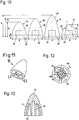
- FIGS. 11 to 13 show the displacement body 16 in detail. From its flat bottom of the displacement body 16 has the center of the opening 23, which, as Fig. 13 shows, is slightly conical and in the direction of the flattened tip 70 of the displacement body 16 tapers.
- the displacement body 16 also has an outer jacket 71, which is connected via stiffening ribs 64 with the opening 23 surrounding area. Radially between the opening 23 and the outer jacket 71 four recesses 72 are arranged, which are separated from each other by the stiffening ribs 63. Due to the stiffening ribs 63, a low weight and a high stability of the displacement body 16 result.
- the displacement body 16 can be produced well by injection molding because of the depressions 72, since material accumulations are thus avoided. As a result, a smooth outer contour of the outer jacket 71 can be ensured.
- FIGS. 14 and 15 show cross sections through the handle tube.
- Fig. 14 shows a cross section in the region of the tubular hollow body 52. Like Fig. 14 shows, the thickness of the wall 36 is comparatively constant. In this area, the handle tube 7 was made with displacement body 16.
- Fig. 15 shows a section through the handle tube 7 in the region of the cavity 62.
- the handle tube 7 without displacement body is formed only by introducing a fluid into the interior of the cavity, ie in the fluid pressure method.
- the resulting inner contour 37 is very rough and uneven, so that there is a very large fluctuation in the wall thickness.
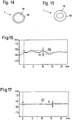
- Fig. 16 shows the variation of the wall thickness as line 66.
- the profile height m ie the distance between the highest profile mountain and the lowest profile valley, is more than 0.5 mm. In the exemplary embodiment, the profile height m is more than 0.6 mm.
- Fig. 17 shows the profile of the tubular hollow body 52 as a line 67.
- the profile height n is very small here and is less than 0.1 mm. Due to the very smooth inner wall in the region of the tubular hollow body 52, the wall thickness can be made very small become. In the region of the cavity 62, the wall thickness must be selected to be larger in order to reliably avoid impermissibly small wall thicknesses.
- the wall thickness in the region of the cavity 62 is in the embodiment of about 5 mm to about 6.5 mm.
- the wall thickness of the handle tube 7 in the region of the tubular hollow body 52 is less than 2 mm.
Landscapes
- Engineering & Computer Science (AREA)
- Mechanical Engineering (AREA)
- Life Sciences & Earth Sciences (AREA)
- Manufacturing & Machinery (AREA)
- Wood Science & Technology (AREA)
- Forests & Forestry (AREA)
- Injection Moulding Of Plastics Or The Like (AREA)
- Moulds For Moulding Plastics Or The Like (AREA)
- Prostheses (AREA)
Abstract
Description
- Die Erfindung betrifft einen Kunststoffkörper und eine Fertigungsanlage zur Herstellung eines Kunststoffkörpers.
- Aus der
US 5,948,343 sind ein Hohlkörper und ein Verfahren zur Herstellung des Hohlkörpers bekannt, bei dem durch die Spritzgussform eine Kugel als Verdrängungskörper gedrückt wird. Die Kugel ist während des Einfüllens der Schmelze in der Spritzgussform gehalten und tritt am gegenüberliegenden Ende des Kunststoffkörpers zusammen mit der verdrängten Schmelze in eine Nebenkavität aus. Dadurch besitzt der Kunststoffkörper an seinen Enden große Öffnungen, deren Durchmesser dem Innendurchmesser des Kunststoffkörpers entspricht. - Es ist auch bekannt, den Verdrängungskörper in dem Kunststoffkörper zu belassen, so dass eine große Austrittsöffnung vermieden werden kann.
- Der Erfindung liegt die Aufgabe zugrunde, einen Kunststoffkörper anzugeben, der ein geringes Gewicht, eine hohe Stabilität und eine hohe Maßhaltigkeit besitzt. Eine weitere Aufgabe der Erfindung besteht darin, eine Fertigungsanlage zur Herstellung eines Kunststoffkörpers mit geringem Gewicht, hoher Stabilität und hoher Maßhaltigkeit anzugeben.
- Diese Aufgabe wird durch einen Kunststoffkörper mit den Merkmalen des Anspruchs 1 gelöst. Bezüglich der Fertigungsanlage wird die Aufgabe durch eine Fertigungsanlage mit den Merkmalen des Anspruchs 11 gelöst.
- Dadurch, dass der Kunststoffkörper in seinem mittleren Bereich als rohrförmiger Hohlkörper ausgebildet ist, ergibt sich eine hohe Stabilität bei geringem Gewicht. Dadurch, dass der Verdrängungskörper an einem Ende des rohrförmigen Hohlkörpers am Übergang zum ersten Vollkörper angeordnet ist, der Verdrängungskörper also im Kunststoffkörper verbleibt, kann eine große Austrittsöffnung für den Verdrängungskörper vermieden werden, so dass eine weitgehend geschlossene Außenfläche des Kunststoffkörpers herstellbar ist und als einzige Öffnung eine Öffnung für die Injektordüse verbleiben muss. Der rohrförmige Hohlkörper ist dabei vorteilhaft in einem Projektilinjektions-Verfahren hergestellt, bei dem der Verdrängungskörper durch den mittleren Bereich geschoben wurde, und zwar von einem Fluid. Der am zweiten Ende des rohrförmigen Hohlkörpers ausgebildete Hohlraum ist dagegen nicht von dem Verdrängungskörper hergestellt, sondern nur vom Fluid. Dadurch kann ein Einfallen des Kunststoffs am zweiten Ende des rohrförmigen Hohlkörpers vermieden werden. Der Hohlraum wird bei der Herstellung durch entsprechend langes Halten des Fluiddrucks erzeugt. Der Hohlraum ist demnach nicht in einem Projektilinnendruck-Verfahren, sondern in einem Fluidinnendruck-Verfahren hergestellt. Durch die Kombination der beiden auf unterschiedliche Weise hergestellten Abschnitte des Kunststoffkörpers lässt sich ein geringes Gewicht des Kunststoffkörpers herstellen. Gleichzeitig kann der mittlere Bereich so angeordnet werden, dass sich keine zu starken Umlenkungen und Richtungsänderungen für den Verdrängungskörper bei der Herstellung ergeben. Die Position, in der die Injektordüse in den Kunststoffkörper ragt, kann so gewählt werden, dass die Öffnung nicht stört, beispielsweise durch eine Positionierung derart, dass sie durch andere Bauteile verdeckt wird oder als Befestigungsöffnung nutzbar ist.
- Der rohrförmige Hohlkörper besitzt an seiner Innenwandung vorteilhaft eine sehr geringe Rauheit. Die maximale Profilhöhe, also der Abstand zwischen der Linie der Profilkuppen und der Profiltäler beträgt vorteilhaft weniger als 0,1 mm. Die Wandstärke ist sehr gering. Im Bereich des Hohlkörpers ist die maximale Profilhöhe um ein Vielfaches größer und beträgt insbesondere mehr als 0,3 mm, insbesondere mehr als 0,5 mm. Die Wandstärke in diesem Bereich beträgt ein Vielfaches, vorteilhaft etwa das 2,5fache bis etwa das 5fache der Wandstärke des rohrförmigen Hohlkörpers.
- Es ist vorgesehen, dass der Verdrängungskörper eine Öffnung für einen Aufsteckabschnitt einer Injektordüse besitzt. Dadurch kann der Verdrängungskörper bei der Herstellung vor dem Einbringen von Schmelze auf die Injektordüse aufgesetzt werden. Dadurch kann die bei der Herstellung entstehende Öffnung ins Innere des Kunststoffkörpers klein gehalten werden. Der rohrförmige Hohlkörper ist insbesondere an einem Ende geschlossen und an dem anderen Ende bis auf die durch die Injektordüse gebildete Öffnung geschlossen. Die Öffnung im Verdrängungskörper ist dabei insbesondere konisch, so dass der Verdrängungskörper fest auf die Injektordüse aufgesteckt werden kann.
- Die Gestaltung des Verdrängungskörpers ist beeinflusst durch die Streuung der Wanddicke des Kunststoffkörpers. Um eine möglichst geringe Streuung der Wanddicke zu erreichen und dadurch geringe Wanddicken zu ermöglichen, ist vorgesehen, dass der Verdrängungskörper einen zylindrischen Abschnitt und einen sich verjüngenden Abschnitt besitzt, wobei der sich verjüngende Abschnitt in den Vollkörper ragt. Der zylindrische Abschnitt formt dabei insbesondere die Abschnitte aus, in denen der Kunststoffkörper gerade verläuft, während der sich verjüngende Abschnitt Biegungen des Kunststoffkörpers ausformt. Vorteilhaft ist der sich verjüngende Abschnitt als Paraboloid oder als Rotationskörper aus einem Kreissegment ausgebildet. Das Verhältnis der Höhe des Verdrängungskörpers zum Durchmesser im zylindrischen Abschnitt beträgt vorteilhaft von etwa 0,6 bis etwa 2. Als besonders vorteilhaft hat sich ein Verhältnis von Höhe zu Durchmesser von etwa 1,25 herausgestellt. Der zylindrische Abschnitt ist vorteilhaft schmal ausgebildet. Die Höhe des zylindrischen Abschnitts beträgt bezogen auf den Durchmesser im zylindrischen Abschnitt vorteilhaft von etwa 0,1 bis etwa 0,3. Der Durchmesser des zylindrischen Abschnitts entspricht dabei dem größten Durchmesser des sich verjüngenden Abschnitts.
- Um ein geringes Gewicht des Verdrängungskörpers bei hoher Steifigkeit zu erreichen, ist vorteilhaft vorgesehen, dass der Verdrängungskörper an der den Hohlkörper begrenzenden Seite mindestens eine Versteifungsrippe besitzt. Es ist vorgesehen, dass der Kunststoffkörper eine Injektoröffnung besitzt. Das Verhältnis des Durchmessers der Injektoröffnung zum Durchmesser des Verdrängungskörpers ist vorteilhaft kleiner als etwa 0,7, insbesondere kleiner als etwa 0,5, vorteilhaft kleiner als etwa 0,3. Dadurch ergibt sich eine geringe Beeinträchtigung der Ergonomie und des Erscheinungsbildes des Kunststoffkörpers durch die Injektoröffnung bei geringem Gewicht des Kunststoffkörpers.
- Der Verdrängungskörper, der im Kunststoffkörper verbleibt, wird vorteilhaft dazu genutzt, einen allmählichen Steifigkeitsübergang vom Hohlkörper zum ersten Vollkörper auszubilden. Über die Gestaltung und das Material des Verdrängungskörpers kann dieser Steifigkeitsübergang eingestellt werden. Vorteilhaft ist die Festigkeit des Kunststoffkörpers im Bereich des Verdrängungskörpers geringer als im Bereich des ersten Vollkörpers und größer als die Festigkeit des Hohlkörpers. Dadurch werden große Steifigkeitssprünge beim Übergang von Hohlkörper zu Vollkörper vermieden. Um ein geringes Gewicht zu erreichen, ist vorgesehen, dass die Gesamtlänge der Vollkörper weniger als 50% der Länge des rohrförmigen Hohlkörpers beträgt. Der Kunststoffkörper ist insbesondere ein Griffrohr für ein tragbares, handgeführtes Arbeitsgerät.
- Für die Fertigungsanlage ist vorgesehen, dass die Injektordüse einen Aufsteckabschnitt für einen Verdrängungskörper besitzt. Dadurch kann der Verdrängungskörper in der Kavität angeordnet werden, so dass kein Eindringen des Verdrängungskörpers durch die Außenwand des Kunststoffkörpers während des Spritzgussvorgangs notwendig ist. Die benötigte Öffnung im Kunststoffkörper ist nur durch den Außendurchmesser der Injektordüse begrenzt, der deutlich kleiner als der Außendurchmesser des Verdrängungskörpers gewählt werden kann. Die kleine Öffnung ermöglicht die Herstellung des Kunststoffkörpers mit Gasinjektion bei geringer Einschränkung der Gestaltungsfreiheit. Ist der Kunststoffkörper ein Griffrohr, so ermöglicht die kleine Öffnung die Herstellung mit Gasinjektion ohne Restriktion an die Ergonomie des Griffrohrs in diesem Bereich. Die Kavität besitzt dabei eine längliche Gestalt mit einem ersten Ende und einem zweiten Ende. Die längliche Gestalt kennzeichnet dabei eine Gestaltung mit einem ersten und einem zweiten Ende, zwischen denen sich die Kavität erstreckt. Die Kavität kann dabei gewunden sein und unterschiedliche Querschnitte besitzen. Die Injektordüse ist dabei zwischen den Enden der Kavität angeordnet. Dadurch ist eine variable Positionierung der Injektordüse möglich. Gleichzeitig kann von der Injektordüse in Richtung auf das eine Ende ein rohrförmiger Hohlkörper in einem Projektilinnendruck-Verfahren hergestellt werden und in Richtung auf das andere Ende ein Hohlraum in einem Fluidinnendruck-Verfahren. Dadurch ist ein Einfallen des Kunststoffkörpers an seinen Endbereichen vermieden, und es wird ein geringes Gewicht bei hoher Stabilität erreicht.
- Vorteilhaft beträgt das Verhältnis des größten Durchmessers des Aufsteckabschnitts zum Durchmesser des Verdrängungskörpers weniger als etwa 0,7, insbesondere weniger als etwa 0,5, vorteilhaft weniger als 0,3. Die Öffnung, die der Aufsteckabschnitt im Kunststoffkörper abbildet, ist dadurch deutlich kleiner als der freie Querschnitt im rohrförmigen Hohlkörper des Kunststoffkörpers.
- Um eine sichere Fixierung des Verdrängungskörpers an der Injektordüse sicherzustellen, ist vorgesehen, dass der Aufsteckabschnitt konisch ausgebildet ist. So können Fertigungstoleranzen des Verdrängungskörpers ausgeglichen werden. Der Aufsteckabschnitt ist vorteilhaft vergleichweise lang und dünn ausgebildet. Der Aufsteckabschnitt ist dabei vorteilhaft zugleich der Abschnitt der Injektordüse, der durch die Wand des Kunststoffkörpers in den innenliegenden Hohlraum ragt.
- Die Injektordüse ist vorteilhaft auch in ihrem größten Durchmesser vergleichsweise klein ausgebildet. Das Verhältnis des Außendurchmessers des Kunststoffkörpers in seinem rohrförmigen Bereich zum größten Durchmesser der Injektordüse ist vorteilhaft größer als etwa 1,3, insbesondere größer als etwa 2, vorteilhaft größer als etwa 3. Dadurch ist die Vertiefung, die die Injektordüse in der Außenwand des Kunststoffkörpers hinterlässt, vergleichsweise klein.
- Um zu vermeiden, dass der Verdrängungskörper durch den Anguss aus der Kavität austreten kann, ist vorgesehen, dass der Durchmesser des Angusses kleiner als der Durchmesser des Verdrängungskörpers ist. Vorteilhaft besitzt die Fertigungsanlage eine Nebenkavität, die über ein Absperrelement von der Kavität trennbar ist. In die Nebenkavität kann überschüssige Schmelze durch den Verdrängungskörper ausgeschoben werden. Vorteilhaft verbleibt der Verdrängungskörper in der Kavität und in dem Kunststoffkörper. Um zu vermeiden, dass der Verdrängungskörper in die Nebenkavität austreten kann, ist vorgesehen, dass die Verbindungsöffnung von Kavität und Nebenkavität einen Durchmesser besitzt, der kleiner als der Durchmesser des Verdrängungskörpers ist. Vorteilhaft werden die Schmelze und das Fluid von gegenüberliegenden Seiten der Kavität aus in die Kavität eingefüllt. Dadurch wird auch ein Verrutschen des Verdrängungskörpers vermieden. Der Verdrängungskörper wird von der Schmelze auf die Injektordüse gedrückt.
-
- Fig. 1
- eine schematische Seitenansicht einer Motorsäge,
- Fig. 2
- eine schematische Darstellung des Griffrohrs der Motorsäge,
- Fig. 3
- eine schematische Darstellung einer Fertigungsanlage zur Herstellung des Griffrohrs,
- Fig. 4
- eine Seitenansicht der Injektordüse,
- Fig. 5 bis Fig. 7
- schematische Schnittdarstellungen, die den Fertigungsvorgang erläutern,
- Fig. 8
- eine schematische Darstellung des Verdrängungskörpers beim Durchtritt durch das Griffrohr,
- Fig. 9
- ein Diagramm, das die Wandstärke in Abhängigkeit des Umlenkwinkels des Verdrängungskörpers zeigt,
- Fig. 10
- eine schematische Darstellung von Ausführungsformen des Verdrängungskörpers,
- Fig. 11
- eine perspektivische Darstellung des Verdrängungskörpers aus
Fig. 2 , - Fig. 12
- eine Seitenansicht des Verdrängungskörpers aus
Fig. 11 , - Fig. 13
- eine Schnittdarstellung entlang der Linie XIII-XIII in
Fig. 12 , - Fig. 14
- eine schematische Schnittdarstellung durch das Griffrohr im Bereich des rohrförmigen Hohlkörpers,
- Fig. 15
- eine schematische Schnittdarstellung durch das Griffrohr im Bereich des Hohlraums,
- Fig. 16
- ein Diagramm, das die Profilhöhe der Innenwand im Bereich des Hohlraums zeigt und
- Fig. 17
- ein Diagramm, das die Profilhöhe der Innenwand im Bereich des rohrförmigen Hohlkörpers zeigt.
-
Fig. 1 zeigt als Ausführungsbeispiel für ein handgeführtes Arbeitsgerät eine Motorsäge 1. Die Motorsäge 1 besitzt ein Gehäuse 2, in dem ein Antriebsmotor 3 angeordnet ist. Der Antriebsmotor 3 ist vorteilhaft als Verbrennungsmotor ausgebildet. Die Motorsäge 1 besitzt eine Führungsschiene 4, an der eine Sägekette 5 angeordnet ist, die von dem Antriebsmotor 3 angetrieben ist. An dem Gehäuse 2 sind ein hinterer Handgriff 6 und ein Griffrohr 7 über Antivibrationselemente 8 festgelegt. Das Griffrohr 7 ist als Bügelgriff ausgebildet. Entsprechende Bügelgriffe werden auch bei anderen handgeführten Arbeitsgeräten, beispielsweise bei Trennschleifern oder dgl. eingesetzt. -
Fig. 2 zeigt den Aufbau des Griffrohrs 7 im Einzelnen. Das Griffrohr 7 besitzt einen ersten Endbereich 9, an dem ein erster Befestigungsabschnitt 11 ausgebildet ist. Der Befestigungsabschnitt 11 dient zur Fixierung des Griffrohrs 7 an einem Griffrahmen. Zur Fixierung eines Antivibrationselements 8 ist ein Gewindestutzen 15 vorgesehen. Das Griffrohr 7 besitzt einen zweiten Endbereich 10 mit einem zweiten Befestigungsabschnitt 12. Im Bereich des zweiten Endes 10 ist außerdem ein Anschlagstutzen 14 für einen Dämpfer und eine Aufnahme 13 für ein Antivibrationselement 8 angeordnet. Das Griffrohr 7 besitzt einen mittleren Bereich, der als rohrförmiger Hohlkörper 52 ausgebildet ist. Der rohrförmige Hohlkörper 52 besitzt ein erstes Ende 55 benachbart zum zweiten Endbereich 10 und ein zweites Ende 56, das benachbart zum ersten Endbereich 9 angeordnet ist. Am ersten Ende 55 ist der rohrförmige Hohlkörper 52 von einem ersten Vollkörper 53 verschlossen. Der erste Vollkörper 53 besitzt eine in Längsrichtung des Griffrohrs 7 gemessene Länge o. Der rohrförmige Hohlkörper 52 besitzt eine in Längsrichtung gemessene Länge q. An den ersten Vollkörper 53 schließen sich die Aufnahme 13 und der Anschlagstutzen 14 an. In diesem Bereich besitzt das Griffrohr 7 eine Vielzahl von Rippen 65, die zur Versteifung dienen. Am Übergang vom Hohlkörper 52 zum Vollkörper 53 ist am ersten Ende 55 des Hohlkörpers 52 ein Verdrängungskörper 16 im Inneren des Griffrohrs 7 angeordnet und fest im Außenmaterial des Griffrohrs 7 gehalten. Der Verdrängungskörper 16 ist inFig. 2 schematisch eingezeichnet und von außen nicht sichtbar. Benachbart zum zweiten Ende 56 des Hohlkörpers 52 besitzt das Griffrohr 7 eine Injektoröffnung 59, die das Innere des Hohlkörpers 52 mit der Umgebung verbindet. Die Injektoröffnung 59 besitzt einen kleinsten Durchmesser 1. Das Verhältnis des Durchmessers 1 der Injektoröffnung 59 zum Durchmesser d des Verdrängungskörpers 16 (Fig. 5 ) ist vorteilhaft kleiner als 0,7, insbesondere kleiner als 0,5. - Am zweiten Ende 56 des rohrförmigen Höhlkörpers 52 schließt sich ein Hohlraum 62 an. Im Bereich des Hohlraums 62 ist die Innenwand des Griffrohrs 7 sehr rau, wie im Folgenden noch näher beschrieben wird. Der Hohlraum 62 und damit auch der Hohlkörper 52 sind an diesem Ende von einem zweiten Vollkörper 63 verschlossen. Der zweite Vollkörper 63 besitzt eine in Längsrichtung des Griffrohrs 7 gemessene Länge p. Daran schließt sich der Befestigungsabschnitt 11 an, der ebenfalls Rippen 65 zur Versteifung besitzt.
- Um ein geringes Gewicht des Griffrohrs 7 zu erreichen, ist vorgesehen, dass die Gesamtlänge der Längen o und p der Vollkörper 53 und 63 weniger als 50% der Länge q des rohrförmigen Hohlkörpers 52 betragen. Vorteilhaft beträgt die Summe der Längen o und p weniger als 30% der Länge q. Die Vollkörper 53 und 63 können sehr kurz ausgebildet sein und lediglich zum Verschließen des Hohlkörpers 52 und Hohlraums 62 dienen.
-
Fig. 3 zeigt schematisch eine Fertigungsanlage 57 zur Herstellung des Griffrohrs 7. Die Fertigungsanlage 57 besitzt eine Spritzgussform 17, in der eine Kavität 54 und eine Nebenkavität 20 ausgebildet sind. Die Spritzgussform 17 besitzt ein Absperrelement 21, mit dem die Nebenkavität 20 mit der Kavität 54 verbunden oder von dieser getrennt werden kann. Die Kavität 54 besitzt ein erstes Ende 68, angrenzend zu dem der zweite Endbereich 10 des Griffrohrs 7 abgeformt wird, sowie ein zweites Ende 69, angrenzend zu dem der erste Endbereich 10 des Griffrohrs 7 abgeformt wird. Zur Zufuhr von Kunststoffschmelze ist ein Schmelzenförderer 19 vorgesehen, der mit einem Anguss 18 in die Kavität 54 mündet. Der Anguss 18 ist benachbart zum ersten Ende 68 angeordnet. Benachbart zum ersten Ende 68 ist auch die Nebenkavität 20 an die Kavität 54 angeschlossen. Bei der inFig. 3 gezeigten Gestaltung ist das Absperrelement 21 in Längsrichtung des Griffrohrs 7 zwischen dem Anguss 18 und dem zweiten Ende 69 der Kavität 54 angeordnet. - In einem Abstand zum zweiten Ende 69 ragt eine Injektordüse 22 mit einem konischen Aufsteckabschnitt 31 in die Kavität 54. Der Aufsteckabschnitt 31 besitzt einen größten Durchmesser f (siehe auch
Fig. 4 ). Auf den Aufsteckabschnitt 31 ist ein Verdrängungskörper 16 aufsteckbar, der in dieser Stellung mit 16' bezeichnet ist. Die Injektordüse 22 ist an einen Fluidanschluss 27 angeschlossen, über den ein Fluid, also ein Gas oder eine Flüssigkeit, vorteilhaft ein Gas, insbesondere Stickstoff, in die Kavität 54 zugeführt werden kann. Mit 16" ist eine mittlere Position des Verdrängungskörpers 16 bezeichnet und mit 16 die Endlage des Verdrängungskörpers 16 im Griffrohr 7. - Die Injektordüse 22 besitzt einen größten Durchmesser e, wie auch in
Fig. 4 gezeigt. Der größte Durchmesser e der Injektordüse 22 ist deutlich kleiner als der inFig. 5 gezeigte Durchmesser a des Griffrohrs 7. Das Verhältnis des Durchmessers a des Griffrohrs 7 zum Durchmesser e der Injektordüse ist vorteilhaft größer als etwa 1,3, insbesondere größer als etwa 2, insbesondere größer als etwa 3. Der größte Außendurchmesser der Injektordüse 22 wird vorteilhaft so klein wie möglich ausgeführt, um die Vertiefung an der Außenseite des Griffrohrs 7, die durch die Injektordüse abgebildet wird, möglichst gering zu halten. Auch der Außendurchmesser f des Aufsteckabschnitts 31 wird vorteilhaft so klein wie möglich gewählt. Der Durchmesser f beträgt vorteilhaft weniger als 10 mm. Das Verhältnis des Durchmessers f zum Durchmesser d des Verdrängungskörpers 16 ist vorteilhaft kleiner als etwa 0,7, insbesondere kleiner als etwa 0,5. - Die
Figuren 5 bis 7 verdeutlichen den Verfahrensablauf bei der Herstellung des Griffrohrs 7. Zunächst wird, wie inFig. 5 durch den Pfeil 25 gezeigt, Schmelze über den Anguss 18 vom ersten Ende 68 zum zweiten Ende 69 zugeführt. Der Verdrängungskörper 16 wird vor dem Einfüllen der Schmelze und insbesondere vor dem Schließen der Spritzgussform 17 auf den Aufsteckabschnitt 31 der Injektordüse 22 aufgesteckt und ist zu Beginn der Schmelzezufuhr bereits auf der Injektordüse 22 fest in der Kavität 54 gehalten. Der Schmelzenförderer 19 umfasst eine Schnecke 24 zur Förderung der Schmelze. Der Anguss 18 besitzt einen Durchmesser k, der kleiner als der Durchmesser d des Verdrängungskörpers 16 ist. Der Durchmesser d ist kleiner als der Durchmesser a des Griffrohrs 7. Beim Einfüllen der Schmelze in die Kavität 54 ist das Absperrelement 21, wieFig. 5 zeigt, geschlossen und die Nebenkavität 20 nicht mit der Kavität 54 verbunden. - Nachdem die gesamte Kavität 54 mit Schmelze gefüllt wurde, wird der Anguss 18 von einem Schieber 51 (
Fig. 6 ) verschlossen. Gleichzeitig öffnet das Absperrelement 21 und verbindet die Kavität 54 mit der Nebenkavität 20. WieFig. 6 zeigt, gibt das Absperrelement 21 eine Verbindungsöffnung 58 frei, deren Durchmesser i ebenfalls kleiner als der Durchmesser d des Verdrängungskörpers 16 ist. Nachdem der Schieber 51 geschlossen und das Absperrelement 21 geöffnet wurde, wird Fluid über die Injektordüse 22 zugeführt. Das Fluid drückt den Verdrängungskörper 16 vor sich her durch die Kavität 54. Dies ist durch den Pfeil 26 verdeutlicht. Da der Durchmesser d des Verdrängungskörpers 16 kleiner als der Innendurchmesser a der Kavität 54, der dem Außendurchmesser des Griffrohrs 7 entspricht, ist, verbleibt an der Wandung der Kavität 54 eine Wand 36, die nach dem Entformen die Wand des Griffrohrs 7 bildet. Die Schmelze aus der Kavität 54 wird vom Verdrängungskörper 16 in die Nebenkavität 20 gedrückt. WieFig. 7 zeigt, wird der Verdrängungskörper 16 bis in den Bereich des Absperrelements 21 gedrückt. Hier verbleibt der Verdrängungskörper 16 im Griffrohr 7. Wie dieFiguren 6 und 7 zeigen, strömt das Fluid nicht nur in Richtung auf das erste Ende 68, sondern von der Injektordüse 22 aus auch in Richtung auf das zweite Ende 69. Da in Richtung auf das zweite Ende 69 kein Verdrängungskörper geschoben wird, ergibt sich hier eine unregelmäßige Wandstärke und Wandstruktur. Das in diesem Bereich strömende Fluid bildet den Hohlraum 62 aus, wie inFig. 7 gezeigt. - Wie
Fig. 8 zeigt, besitzt der Verdrängungskörper 16 einen zylindrischen Abschnitt 43 und einen daran anschließenden, sich verjüngenden Abschnitt 44. Der Verdrängungskörper 16 ist in einer Biegung des Griffrohrs 7 gezeigt. Der Verdrängungskörper 16 ist im Inneren des rohrförmigen Hohlkörpers 52 angeordnet. Die Wand 36 des Griffrohrs 7 besitzt eine Wandstärke b. Die Innenfläche der Wand 36 verläuft an ihrer Innenseite mit einem Innenradius r1 und an ihrer Außenseite mit einem Außenradius r2. Der zylindrische Abschnitt 43 berührt die Wand 36 umlaufend und formt so den Innenraum des rohrförmigen Hohlkörpers 52 aus. Der Verdrängungskörper 16 besitzt eine Längsmittelachse 49, die gegenüber einer Tangente 50 an die Innenwand des Hohlkörpers 52 um einen Winkel α geneigt ist. -
Fig. 9 zeigt mit einer Kurve 48 den Zusammenhang zwischen der Wandstärke b und dem Winkel α. In einem ersten Winkelbereich 38 ist die Wandstärke weitgehend konstant. In diesem Winkelbereich formt der zylindrische Abschnitt 43 die Innenkontur. Bei größeren Drehwinkeln α, also im zweiten Winkelbereich 39, kommt der sich verjüngende Abschnitt 44 in Eingriff mit der Innenkontur und formt die Innenkontur aus. Aufgrund der größeren Schrägstellung des Verdrängungskörpers 16 nimmt die Wandstärke b mit zunehmendem Drehwinkel α ab. -
Fig. 10 zeigt unterschiedliche Gestaltungsvarianten für Verdrängungskörper 16, 40, 41 und 42. Alle Verdrängungskörper 16, 40, 41 und 42 besitzen einen zylindrischen Abschnitt 43, der eine Höhe z besitzt, sowie einen größten Durchmesser d und eine Öffnung 23, die zum zylindrischen Abschnitt 43 hin öffnet und die konisch ausgebildet ist. Dies ist für den Verdrängungskörper 42 zur Verdeutlichung stark übertrieben gezeigt. Mit der Öffnung 23 wird der Verdrängungskörper 16, 40, 41, 42 auf die Injektordüse 22 aufgesteckt. An den zylindrischen Abschnitt 43 schließen unterschiedliche, sich verjüngende Abschnitte 44, 45, 46 und 47 an. Die Abschnitte 44, 45 und 46 sind jeweils als Paraboloid ausgebildet, also als Rotationskörper, der sich bei Rotation einer Parabelkurve ergibt. Der Verdrängungskörper 16 besitzt eine Höhe h3, die etwa dem Durchmesser d entspricht. Bei dieser Gestaltung ergeben sich sehr günstige Restwanddicken. Der Verdrängungskörper 40 besitzt eine Höhe h2, die das 1,25fache des Durchmessers d beträgt. Der Verdrängungskörper 41 besitzt eine Höhe h1, die dem 1,5fachen des Durchmessers d entspricht. Mit zunehmendem Verhältnis von Höhe h zu Durchmesser d nimmt der ausformbare minimale Radius ab. Der sich verjüngende Abschnitt 47 ist durch Rotation eines Kreissegments mit dem Radius c gebildet. Die Höhe h4 des Verdrängungskörpers 42 beträgt das 0,8fache bis 0,9fache des Durchmessers d. - Das Verhältnis der Höhe des Verdrängungskörpers 16, 40, 41, 42 zum Durchmesser d des zylindrischen Abschnitts 43 beträgt vorteilhaft von etwa 0,6 bis etwa 2. Das Verhältnis der Höhe z des zylindrischen Abschnitts zum Durchmesser d im zylindrischen Abschnitt beträgt vorteilhaft von etwa 0,1 bis etwa 0,3.
- Durch die in
Fig. 10 gezeigten Profilgestaltungen eines Verdrängungskörpers 16, 40, 41, 42 kann auch die Steifigkeit des Griffrohrs 7 am Übergang vom Hohlkörper 52 zum Vollkörper 53 angepasst werden. Die Steifigkeit des Griffrohrs 7 im Bereich des Verdrängungskörpers 16, 40, 41, 42 liegt vorteilhaft zwischen der Steifigkeit des Hohlkörpers und der Steifigkeit des Vollkörpers. Dadurch wird ein sprunghafter Steifigkeitsübergang des Griffrohrs 7 vermieden, und die Stabilität wird erhöht. Ein sprunghafter Steifigkeitsübergang könnte auch zu einer Verschlechterung der dynamischen Beschleunigungskennwerte führen. Dies wird durch die vorgeschlagene Gestaltung vermieden. - Die
Figuren 11 bis 13 zeigen den Verdrängungskörper 16 im Einzelnen. Von seiner flachen Unterseite aus besitzt der Verdrängungskörper 16 mittig die Öffnung 23, die, wieFig. 13 zeigt, leicht konisch ausgebildet ist und in Richtung auf die abgeflachte Spitze 70 des Verdrängungskörpers 16 hin zuläuft. Der Verdrängungskörper 16 besitzt außerdem einen Außenmantel 71, der über Versteifungsrippen 64 mit dem die Öffnung 23 umgebenden Bereich verbunden ist. Radial zwischen der Öffnung 23 und dem Außenmantel 71 sind vier Vertiefungen 72 angeordnet, die von den Versteifungsrippen 63 voneinander getrennt sind. Aufgrund der Versteifungsrippen 63 ergeben sich ein geringes Gewicht und eine hohe Stabilität des Verdrängungskörpers 16. Der Verdrängungskörper 16 kann aufgrund der Vertiefungen 72 gut im Spritzgussverfahren hergestellt werden, da Materialansammlungen so vermieden werden. Dadurch kann eine glatte Außenkontur des Außenmantels 71 sichergestellt werden. - Die
Figuren 14 und 15 zeigen Querschnitte durch das Griffrohr 7.Fig. 14 zeigt einen Querschnitt im Bereich des rohrförmigen Hohlkörpers 52. WieFig. 14 zeigt, ist die Dicke der Wand 36 vergleichsweise konstant. In diesem Bereich wurde das Griffrohr 7 mit Verdrängungskörper 16 hergestellt. -
Fig. 15 zeigt einen Schnitt durch das Griffrohr 7 im Bereich des Hohlraums 62. In diesem Bereich ist das Griffrohr 7 ohne Verdrängungskörper lediglich durch Einbringen eines Fluids ins Innere der Kavität, also im Fluidinnendruck-Verfahren gebildet. Die sich ergebende Innenkontur 37 ist sehr rau und ungleichmäßig, so dass sich eine sehr große Schwankungsbreite in der Wanddicke ergibt. -
Fig. 16 zeigt die Schwankung der Wanddicke als Linie 66. Die Profilhöhe m, also der Abstand zwischen dem höchsten Profilberg und dem niedrigsten Profiltal, beträgt mehr als 0,5 mm. Im Ausführungsbeispiel beträgt die Profilhöhe m mehr als 0,6 mm. -
Fig. 17 zeigt das Profil des rohrförmigen Hohlkörpers 52 als Linie 67. Die Profilhöhe n ist hier sehr gering und beträgt weniger als 0,1 mm. Durch die sehr glatte Innenwand im Bereich des rohrförmigen Hohlkörpers 52 kann die Wanddicke sehr gering ausgebildet werden. Im Bereich des Hohlraums 62 muss die Wanddicke größer gewählt werden, um unzulässig geringe Wanddicken zuverlässig zu vermeiden. Die Wanddicke im Bereich des Hohlraums 62 beträgt im Ausführungsbeispiel von etwa 5 mm bis etwa 6,5 mm. Die Wanddicke des Griffrohrs 7 im Bereich des rohrförmigen Hohlkörpers 52 beträgt weniger als 2 mm.
Claims (16)
- Kunststoffkörper, insbesondere ein Griffrohr (7) für ein tragbares, handgeführtes Arbeitsgerät, wobei der Kunststoffkörper in einem mittleren Bereich als rohrförmiger Hohlkörper (52) ausgebildet ist, wobei der rohrförmige Hohlkörper (52) an beiden Enden (55, 56) jeweils von einem geschlossenen Vollkörper (53, 63) verschlossen ist, wobei an einem ersten Ende (55) des rohrförmigen Hohlkörpers (52) ein Verdrängungskörper (16, 40, 41, 42) angeordnet ist, der am Übergang vom Hohlkörper (52) zum ersten Vollkörper (53) angeordnet ist, und wobei an einem zweiten Ende (56) des rohrförmigen Hohlkörpers (52) ein Hohlraum ausgebildet ist, der sich zwischen dem rohrförmigen Hohlkörper (52) und dem zweiten Vollkörper (63) erstreckt.
- Kunststoffkörper nach Anspruch 1,
dadurch gekennzeichnet, dass der Verdrängungskörper (16, 40, 41, 42) eine Öffnung (23) für einen Aufsteckabschnitt (31) einer Injektordüse (22) besitzt. - Kunststoffkörper nach Anspruch 2,
dadurch gekennzeichnet, dass der Verdrängungskörper (16, 40, 41, 42) einen zylindrischen Abschnitt (43) und einen sich verjüngenden Abschnitt (44, 45, 46, 47) besitzt, wobei der sich verjüngende Abschnitt (44, 45, 46, 47) in den ersten Vollkörper (53) ragt. - Kunststoffkörper nach Anspruch 3,
dadurch gekennzeichnet, dass der sich verjüngende Abschnitt (44, 45, 46) des Verdrängungskörpers (16, 40, 41) als Paraboloid ausgebildet ist. - Kunststoffkörper nach Anspruch 3,
dadurch gekennzeichnet, dass der sich verjüngende Abschnitt (47) des Verdrängungskörpers (42) ein Rotationskörper aus einem Kreissegment ist. - Kunststoffkörper nach einem der Ansprüche 3 bis 5,
dadurch gekennzeichnet, dass das Verhältnis der Höhe (h1, h2, h3, h4) des Verdrängungskörpers (16, 40, 41, 42) zum Durchmesser (d) des zylindrischen Abschnitts (43) des Verdrängungskörpers (16, 40, 41, 42) von etwa 0,6 bis etwa 2 beträgt, wobei das Verhältnis der Höhe (z) des zylindrischen Abschnitts (43) zum Durchmesser (d) im zylindrischen Abschnitt insbesondere von etwa 0,1 bis etwa 0,3 beträgt. - Kunststoffkörper nach einem der Ansprüche 1 bis 6,
dadurch gekennzeichnet, dass der Verdrängungskörper (16, 40, 41, 42) an der den Hohlkörper (52) begrenzenden Seite mindestens eine Versteifungsrippe (64) besitzt. - Kunststoffkörper nach einem der Ansprüche 1 bis 7,
dadurch gekennzeichnet, dass der Kunststoffkörper eine Injektoröffnung (59) besitzt, die etwa zwischen dem rohrförmigen Hohlkörper (52) und dem Hohlraum (62) angeordnet ist, wobei die Injektoröffnung (59) insbesondere die einzige Verbindung des Hohlkörpers (52) nach außen ist, wobei das Verhältnis des Durchmessers (1) der Injektoröffnung (59) zum Durchmesser (d) des Verdrängungskörpers (16, 40, 41, 42) vorteilhaft kleiner als etwa 0,7, insbesondere kleiner als etwa 0,5, vorteilhaft kleiner als etwa 0,3 ist. - Kunststoffkörper nach einem der Ansprüche 1 bis 8,
dadurch gekennzeichnet, dass die Festigkeit des Kunststoffkörpers im Bereich des Verdrängungskörpers (16, 40, 41, 42) geringer als die Festigkeit des ersten Vollkörpers (53) und größer als die Festigkeit des Hohlkörpers (52) ist. - Kunststollkörper nach einem der Ansprüche 1 bis 9,
dadurch gekennzeichnet, dass die Gesamtlänge des ersten und zweiten Vollkörpers (53, 63) weniger als 50% der Länge (q) des rohrförmigen Hohlkörpers (52) beträgt. - Fertigungsanlage zur Herstellung eines mindestens teilweise rohrförmigen Kunststoffkörpers in einem Spritzgussverfahren, mit einer Spritzgussform (17), die eine Kavität (54) begrenzt und die einen Anguss (18) zur Zufuhr von Kunststoffschmelze und eine Injektordüse (22) zur Einbringung von Fluid besitzt, wobei die Injektordüse (22) einen Aufsteckabschnitt (31) für einen Verdrängungskörper (16, 40, 41, 42) besitzt, dadurch gekennzeichnet, dass die Kavität (54) eine längliche Gestalt mit einem ersten Ende (68) und einem zweiten Ende (69) besitzt und dass die Injektordüse (22) zwischen den Enden (68, 69) der Kavität (54) angeordnet ist.
- Fertigungsanlage nach Anspruch 11,
dadurch gekennzeichnet, dass das Verhältnis des größten Durchmessers (f) des Aufsteckabschnitts (31) zum Durchmesser (d) des Verdrängungskörpers (16, 40, 41, 42) kleiner als etwa 0,7, insbesondere kleiner als etwa 0,5, vorteilhaft kleiner als 0,3 ist. - Fertigungsanlage nach Anspruch 11 oder 12,
dadurch gekennzeichnet, dass der Aufsteckabschnitt (31) konisch ausgebildet ist. - Fertigungsanlage nach einem der Ansprüche 11 bis 13,
dadurch gekennzeichnet, dass das Verhältnis des Außendurchmessers (a) des Kunststoffkörpers in seinem rohrförmigen Bereich zum größten Durchmesser (e) der Injektordüse (22) größer als etwa 1,3, insbesondere größer als etwa 2, vorteilhaft größer als etwa 3 ist. - Fertigungsanlage nach einem der Ansprüche 11 bis 14,
dadurch gekennzeichnet, dass der Durchmesser (k) des Angusses (18) kleiner als der Durchmesser (d) des Verdrängungskörpers (16, 40, 41, 42) ist. - Fertigungsanlage nach einem der Ansprüche 11 bis 15,
dadurch gekennzeichnet, dass die Fertigungsanlage (57) eine Nebenkavität (20) besitzt, die über ein Absperrelement (21) von der Kavität (54) trennbar ist, wobei die Verbindungsöffnung (58) von Kavität (54) und Nebenkavität (20) insbesondere einen Durchmesser (i) besitzt, der kleiner als der Durchmesser (d) des Verdrängungskörpers (16, 40, 41, 42) ist.
Priority Applications (1)
| Application Number | Priority Date | Filing Date | Title |
|---|---|---|---|
| PL12001458T PL2505332T3 (pl) | 2011-03-30 | 2012-03-03 | Korpus z tworzywa sztucznego i system do wytwarzania korpusu z tworzywa sztucznego |
Applications Claiming Priority (1)
| Application Number | Priority Date | Filing Date | Title |
|---|---|---|---|
| DE102011015522A DE102011015522A1 (de) | 2011-03-30 | 2011-03-30 | Kunststoffkörper und Fertigungsanlage zur Herstellung eines Kunststoffkörpers |
Publications (2)
| Publication Number | Publication Date |
|---|---|
| EP2505332A1 true EP2505332A1 (de) | 2012-10-03 |
| EP2505332B1 EP2505332B1 (de) | 2013-12-11 |
Family
ID=45877944
Family Applications (1)
| Application Number | Title | Priority Date | Filing Date |
|---|---|---|---|
| EP12001458.4A Active EP2505332B1 (de) | 2011-03-30 | 2012-03-03 | Kunststoffkörper und System zur Herstellung eines Kunststoffkörpers |
Country Status (7)
| Country | Link |
|---|---|
| US (1) | US8697209B2 (de) |
| EP (1) | EP2505332B1 (de) |
| JP (1) | JP5914096B2 (de) |
| CN (1) | CN102729226B (de) |
| DE (1) | DE102011015522A1 (de) |
| PL (1) | PL2505332T3 (de) |
| RU (1) | RU2585282C2 (de) |
Cited By (2)
| Publication number | Priority date | Publication date | Assignee | Title |
|---|---|---|---|---|
| CN104552745A (zh) * | 2015-01-31 | 2015-04-29 | 长春中拓模塑科技有限公司 | 热塑性树脂中空管制品注塑成型系统 |
| EP3000580A1 (de) * | 2014-09-24 | 2016-03-30 | Plastimark S.p.A. | Verfahren zur herstellung eines schiebegriffs für einkaufswagen und ein schiebegriff für einkaufswagen |
Families Citing this family (9)
| Publication number | Priority date | Publication date | Assignee | Title |
|---|---|---|---|---|
| CN104552766A (zh) * | 2015-01-31 | 2015-04-29 | 长春中拓模塑科技有限公司 | 热塑性树脂中空管制品注塑成型系统及成型方法 |
| DE102016200484C5 (de) | 2016-01-15 | 2022-12-01 | Kautex Textron Gmbh & Co. Kg | Verfahren und Vorrichtung zur Herstellung eines rohrförmigen Bauteils aus thermoplastischem Kunststoff durch Spritzgießen |
| DE102019126566B4 (de) | 2019-10-02 | 2023-06-22 | Dr. Ing. H.C. F. Porsche Aktiengesellschaft | Projektil für ein Projektil-Injektionsverfahren und Verfahren zum Herstellen eines gekrümmten Hohlprofilbauteils |
| US11413782B2 (en) * | 2019-10-18 | 2022-08-16 | Globe (Jiangsu) Co., Ltd | Chain saw |
| DE102020206045A1 (de) | 2020-05-13 | 2021-11-18 | Ford Global Technologies, Llc | Verfahren zur Herstellung eines Hohlkörper-Verbundbauteils, sowie Projektil zum Einsatz in einem solchen Verfahren |
| EP4008491A1 (de) * | 2020-12-04 | 2022-06-08 | Hilti Aktiengesellschaft | Werkzeugmaschine mit einem ersten griff, einem zweiten griff und einem hauptkörper |
| FR3119111B1 (fr) * | 2021-01-28 | 2024-10-11 | Renault Sas | Système d’injection d’une matière plastique, procédé de fabrication d’une pièce injectée. |
| CN113276340B (zh) * | 2021-05-28 | 2023-05-05 | 上海延锋金桥汽车饰件系统有限公司 | 一种嵌件注塑方法及通过该嵌件注塑方法形成的注塑件 |
| CN113320085B (zh) * | 2021-05-28 | 2022-11-01 | 上海延锋金桥汽车饰件系统有限公司 | 多级投射物、部件的成型方法及部件 |
Citations (4)
| Publication number | Priority date | Publication date | Assignee | Title |
|---|---|---|---|---|
| US4964217A (en) * | 1988-04-08 | 1990-10-23 | Andreas Stihl | Handle for a chain saw |
| US5948343A (en) | 1995-02-23 | 1999-09-07 | Rp Topla Limited | Hollow shaped molded article, hollow shaped molding process and hollow shaped molding device |
| WO2010116580A1 (ja) * | 2009-04-10 | 2010-10-14 | アァルピィ東プラ株式会社 | 中空体の製造方法 |
| EP2377665A1 (de) * | 2010-04-17 | 2011-10-19 | Wittmann Battenfeld GmbH | Vorrichtung und Verfahren zum Spritzgiessen eines mindestens einen Hohlraum aufweisenden Formteils |
Family Cites Families (4)
| Publication number | Priority date | Publication date | Assignee | Title |
|---|---|---|---|---|
| DE3811788C2 (de) * | 1988-04-08 | 1998-10-01 | Stihl Maschf Andreas | Bügelförmiger, einstückiger Griff aus Kunststoff |
| DE4321652B4 (de) * | 1993-06-30 | 2006-05-11 | Fa. Andreas Stihl | Kunststoffgriff für handgeführte Motorkettensägen |
| US20060005358A1 (en) * | 2004-06-22 | 2006-01-12 | Andreas Stihl Ag & Co. Kg | Handle for a Handheld Working Tool |
| DE102008023473A1 (de) * | 2008-05-14 | 2009-11-19 | Röchling Automotive AG & Co. KG | Kalibrator für Gießverfahren mit Projektilinjektion (PIT) |
-
2011
- 2011-03-30 DE DE102011015522A patent/DE102011015522A1/de not_active Withdrawn
-
2012
- 2012-03-03 EP EP12001458.4A patent/EP2505332B1/de active Active
- 2012-03-03 PL PL12001458T patent/PL2505332T3/pl unknown
- 2012-03-26 RU RU2012111204/04A patent/RU2585282C2/ru active
- 2012-03-28 US US13/432,495 patent/US8697209B2/en active Active
- 2012-03-29 JP JP2012076076A patent/JP5914096B2/ja active Active
- 2012-03-30 CN CN201210099627.8A patent/CN102729226B/zh active Active
Patent Citations (5)
| Publication number | Priority date | Publication date | Assignee | Title |
|---|---|---|---|---|
| US4964217A (en) * | 1988-04-08 | 1990-10-23 | Andreas Stihl | Handle for a chain saw |
| US5948343A (en) | 1995-02-23 | 1999-09-07 | Rp Topla Limited | Hollow shaped molded article, hollow shaped molding process and hollow shaped molding device |
| WO2010116580A1 (ja) * | 2009-04-10 | 2010-10-14 | アァルピィ東プラ株式会社 | 中空体の製造方法 |
| EP2418063A1 (de) * | 2009-04-10 | 2012-02-15 | RP Topla Limited | Verfahren zur herstellung eines hohlkörpers |
| EP2377665A1 (de) * | 2010-04-17 | 2011-10-19 | Wittmann Battenfeld GmbH | Vorrichtung und Verfahren zum Spritzgiessen eines mindestens einen Hohlraum aufweisenden Formteils |
Non-Patent Citations (1)
| Title |
|---|
| "Möglichkeiten und Grenzen der Projektilinjektionstechnik", IKV FACHTAGUNG GAS- UND WASSERINJEKTIONSTECHNIK POTENZIALE NUTZEN, HERAUSFORDERUNGEN MEISTERN,, 28 November 2007 (2007-11-28), pages 1 - 7, XP007905530 * |
Cited By (2)
| Publication number | Priority date | Publication date | Assignee | Title |
|---|---|---|---|---|
| EP3000580A1 (de) * | 2014-09-24 | 2016-03-30 | Plastimark S.p.A. | Verfahren zur herstellung eines schiebegriffs für einkaufswagen und ein schiebegriff für einkaufswagen |
| CN104552745A (zh) * | 2015-01-31 | 2015-04-29 | 长春中拓模塑科技有限公司 | 热塑性树脂中空管制品注塑成型系统 |
Also Published As
| Publication number | Publication date |
|---|---|
| JP2012210812A (ja) | 2012-11-01 |
| PL2505332T3 (pl) | 2014-04-30 |
| CN102729226A (zh) | 2012-10-17 |
| DE102011015522A1 (de) | 2012-10-04 |
| EP2505332B1 (de) | 2013-12-11 |
| US20120276313A1 (en) | 2012-11-01 |
| US8697209B2 (en) | 2014-04-15 |
| RU2012111204A (ru) | 2013-10-10 |
| JP5914096B2 (ja) | 2016-05-11 |
| RU2585282C2 (ru) | 2016-05-27 |
| CN102729226B (zh) | 2016-08-03 |
Similar Documents
| Publication | Publication Date | Title |
|---|---|---|
| EP2505332B1 (de) | Kunststoffkörper und System zur Herstellung eines Kunststoffkörpers | |
| EP1132651B1 (de) | Wälzkörpergewindetrieb | |
| DE602004012654T2 (de) | System zum Spritzgiessen von einem Kunststoffrotationskörper | |
| DE69814654T2 (de) | Saugstrahlpumpe mit einer düse mit variabelem durchschnitt | |
| WO2016058723A1 (de) | Lenkwelle und verfahren zum herstellen einer profilierten hohlwelle für eine teleskopierbare lenkwelle eines kraftfahrzeugs | |
| DE1475035B2 (de) | Befestigungsvorrichtung | |
| DE102014115804B4 (de) | Schneckenrad für eine elektromechanische Hilfskraftlenkung | |
| DE3534901C2 (de) | ||
| DE102014014592A1 (de) | Vorrichtung zum Auftragen eines viskosen Materials | |
| DE1258617B (de) | Drehkolben fuer Volumenzaehler | |
| WO2018138263A1 (de) | Hydrofoil für ein wasserfahrzeug | |
| EP2106333A1 (de) | Spritzenkörper | |
| DE3714479C2 (de) | ||
| WO2014006152A1 (de) | Kugelgewindetrieb | |
| DE102015015122A1 (de) | Verfahren zum Herstellen eines Fluidbehälters für ein Kraftfahrzeug sowie entsprechender Fluidbehälter | |
| DE2227335A1 (de) | Treibriemen und verfahren zu seiner herstellung | |
| DE10260426B3 (de) | Lenkritzel | |
| DE19533052A1 (de) | Austragvorrichtung für Medien sowie Verfahren zur Herstellung einer Austragvorrichtung | |
| DE4242336A1 (de) | Verfahren und Vorrichtung zur kontinuierlichen Herstellung von zylindrischen Stäben mit zumindest einem innenliegenden, wendelförmigen Kanal, und nach diesem Verfahren hergestellter Sinterrohling | |
| EP1655512B1 (de) | Kugelgewindetrieb | |
| DE10247331A1 (de) | Zahnstangenlenkung | |
| DE2442866B2 (de) | ||
| DE4211827C2 (de) | Verfahren und Strangpreßwerkzeug zur kontinuierlichen Herstellung von zylindrischen Stäben mit zumindest einem innenliegenden, wendelförmigen Kanal, und nach diesem Verfahren hergestellter Stab | |
| DE102022104059B3 (de) | Coextrusionswerkzeug zur Herstellung mehrschichtiger, schlauchartiger Vorformlinge aus thermoplastischem Kunststoff | |
| DE4211959A1 (de) | Rohrverbindung |
Legal Events
| Date | Code | Title | Description |
|---|---|---|---|
| PUAI | Public reference made under article 153(3) epc to a published international application that has entered the european phase |
Free format text: ORIGINAL CODE: 0009012 |
|
| AK | Designated contracting states |
Kind code of ref document: A1 Designated state(s): AL AT BE BG CH CY CZ DE DK EE ES FI FR GB GR HR HU IE IS IT LI LT LU LV MC MK MT NL NO PL PT RO RS SE SI SK SM TR |
|
| AX | Request for extension of the european patent |
Extension state: BA ME |
|
| 17P | Request for examination filed |
Effective date: 20130320 |
|
| GRAP | Despatch of communication of intention to grant a patent |
Free format text: ORIGINAL CODE: EPIDOSNIGR1 |
|
| RIC1 | Information provided on ipc code assigned before grant |
Ipc: B27B 17/00 20060101ALI20130625BHEP Ipc: B29C 45/00 20060101ALN20130625BHEP Ipc: B25F 5/02 20060101ALI20130625BHEP Ipc: B29C 45/17 20060101AFI20130625BHEP |
|
| INTG | Intention to grant announced |
Effective date: 20130716 |
|
| GRAS | Grant fee paid |
Free format text: ORIGINAL CODE: EPIDOSNIGR3 |
|
| GRAA | (expected) grant |
Free format text: ORIGINAL CODE: 0009210 |
|
| AK | Designated contracting states |
Kind code of ref document: B1 Designated state(s): AL AT BE BG CH CY CZ DE DK EE ES FI FR GB GR HR HU IE IS IT LI LT LU LV MC MK MT NL NO PL PT RO RS SE SI SK SM TR |
|
| REG | Reference to a national code |
Ref country code: GB Ref legal event code: FG4D Free format text: NOT ENGLISH |
|
| REG | Reference to a national code |
Ref country code: CH Ref legal event code: EP |
|
| REG | Reference to a national code |
Ref country code: AT Ref legal event code: REF Ref document number: 644251 Country of ref document: AT Kind code of ref document: T Effective date: 20140115 |
|
| REG | Reference to a national code |
Ref country code: IE Ref legal event code: FG4D Free format text: LANGUAGE OF EP DOCUMENT: GERMAN |
|
| REG | Reference to a national code |
Ref country code: DE Ref legal event code: R096 Ref document number: 502012000251 Country of ref document: DE Effective date: 20140206 |
|
| REG | Reference to a national code |
Ref country code: NL Ref legal event code: VDEP Effective date: 20131211 |
|
| PG25 | Lapsed in a contracting state [announced via postgrant information from national office to epo] |
Ref country code: NL Free format text: LAPSE BECAUSE OF FAILURE TO SUBMIT A TRANSLATION OF THE DESCRIPTION OR TO PAY THE FEE WITHIN THE PRESCRIBED TIME-LIMIT Effective date: 20131211 Ref country code: SE Free format text: LAPSE BECAUSE OF FAILURE TO SUBMIT A TRANSLATION OF THE DESCRIPTION OR TO PAY THE FEE WITHIN THE PRESCRIBED TIME-LIMIT Effective date: 20131211 Ref country code: LT Free format text: LAPSE BECAUSE OF FAILURE TO SUBMIT A TRANSLATION OF THE DESCRIPTION OR TO PAY THE FEE WITHIN THE PRESCRIBED TIME-LIMIT Effective date: 20131211 Ref country code: NO Free format text: LAPSE BECAUSE OF FAILURE TO SUBMIT A TRANSLATION OF THE DESCRIPTION OR TO PAY THE FEE WITHIN THE PRESCRIBED TIME-LIMIT Effective date: 20140311 Ref country code: FI Free format text: LAPSE BECAUSE OF FAILURE TO SUBMIT A TRANSLATION OF THE DESCRIPTION OR TO PAY THE FEE WITHIN THE PRESCRIBED TIME-LIMIT Effective date: 20131211 Ref country code: HR Free format text: LAPSE BECAUSE OF FAILURE TO SUBMIT A TRANSLATION OF THE DESCRIPTION OR TO PAY THE FEE WITHIN THE PRESCRIBED TIME-LIMIT Effective date: 20131211 |
|
| REG | Reference to a national code |
Ref country code: PL Ref legal event code: T3 |
|
| REG | Reference to a national code |
Ref country code: LT Ref legal event code: MG4D |
|
| PG25 | Lapsed in a contracting state [announced via postgrant information from national office to epo] |
Ref country code: LV Free format text: LAPSE BECAUSE OF FAILURE TO SUBMIT A TRANSLATION OF THE DESCRIPTION OR TO PAY THE FEE WITHIN THE PRESCRIBED TIME-LIMIT Effective date: 20131211 Ref country code: CY Free format text: LAPSE BECAUSE OF FAILURE TO SUBMIT A TRANSLATION OF THE DESCRIPTION OR TO PAY THE FEE WITHIN THE PRESCRIBED TIME-LIMIT Effective date: 20131211 Ref country code: RS Free format text: LAPSE BECAUSE OF FAILURE TO SUBMIT A TRANSLATION OF THE DESCRIPTION OR TO PAY THE FEE WITHIN THE PRESCRIBED TIME-LIMIT Effective date: 20131211 |
|
| PG25 | Lapsed in a contracting state [announced via postgrant information from national office to epo] |
Ref country code: IS Free format text: LAPSE BECAUSE OF FAILURE TO SUBMIT A TRANSLATION OF THE DESCRIPTION OR TO PAY THE FEE WITHIN THE PRESCRIBED TIME-LIMIT Effective date: 20140411 Ref country code: EE Free format text: LAPSE BECAUSE OF FAILURE TO SUBMIT A TRANSLATION OF THE DESCRIPTION OR TO PAY THE FEE WITHIN THE PRESCRIBED TIME-LIMIT Effective date: 20131211 |
|
| PG25 | Lapsed in a contracting state [announced via postgrant information from national office to epo] |
Ref country code: ES Free format text: LAPSE BECAUSE OF FAILURE TO SUBMIT A TRANSLATION OF THE DESCRIPTION OR TO PAY THE FEE WITHIN THE PRESCRIBED TIME-LIMIT Effective date: 20131211 Ref country code: RO Free format text: LAPSE BECAUSE OF FAILURE TO SUBMIT A TRANSLATION OF THE DESCRIPTION OR TO PAY THE FEE WITHIN THE PRESCRIBED TIME-LIMIT Effective date: 20131211 Ref country code: PT Free format text: LAPSE BECAUSE OF FAILURE TO SUBMIT A TRANSLATION OF THE DESCRIPTION OR TO PAY THE FEE WITHIN THE PRESCRIBED TIME-LIMIT Effective date: 20140411 Ref country code: CZ Free format text: LAPSE BECAUSE OF FAILURE TO SUBMIT A TRANSLATION OF THE DESCRIPTION OR TO PAY THE FEE WITHIN THE PRESCRIBED TIME-LIMIT Effective date: 20131211 Ref country code: SK Free format text: LAPSE BECAUSE OF FAILURE TO SUBMIT A TRANSLATION OF THE DESCRIPTION OR TO PAY THE FEE WITHIN THE PRESCRIBED TIME-LIMIT Effective date: 20131211 |
|
| REG | Reference to a national code |
Ref country code: DE Ref legal event code: R097 Ref document number: 502012000251 Country of ref document: DE |
|
| PLBE | No opposition filed within time limit |
Free format text: ORIGINAL CODE: 0009261 |
|
| STAA | Information on the status of an ep patent application or granted ep patent |
Free format text: STATUS: NO OPPOSITION FILED WITHIN TIME LIMIT |
|
| PG25 | Lapsed in a contracting state [announced via postgrant information from national office to epo] |
Ref country code: DK Free format text: LAPSE BECAUSE OF FAILURE TO SUBMIT A TRANSLATION OF THE DESCRIPTION OR TO PAY THE FEE WITHIN THE PRESCRIBED TIME-LIMIT Effective date: 20131211 Ref country code: LU Free format text: LAPSE BECAUSE OF FAILURE TO SUBMIT A TRANSLATION OF THE DESCRIPTION OR TO PAY THE FEE WITHIN THE PRESCRIBED TIME-LIMIT Effective date: 20140303 |
|
| 26N | No opposition filed |
Effective date: 20140912 |
|
| REG | Reference to a national code |
Ref country code: DE Ref legal event code: R097 Ref document number: 502012000251 Country of ref document: DE Effective date: 20140912 |
|
| REG | Reference to a national code |
Ref country code: IE Ref legal event code: MM4A |
|
| PG25 | Lapsed in a contracting state [announced via postgrant information from national office to epo] |
Ref country code: IE Free format text: LAPSE BECAUSE OF NON-PAYMENT OF DUE FEES Effective date: 20140303 |
|
| PG25 | Lapsed in a contracting state [announced via postgrant information from national office to epo] |
Ref country code: SI Free format text: LAPSE BECAUSE OF FAILURE TO SUBMIT A TRANSLATION OF THE DESCRIPTION OR TO PAY THE FEE WITHIN THE PRESCRIBED TIME-LIMIT Effective date: 20131211 |
|
| REG | Reference to a national code |
Ref country code: CH Ref legal event code: PL |
|
| PG25 | Lapsed in a contracting state [announced via postgrant information from national office to epo] |
Ref country code: CH Free format text: LAPSE BECAUSE OF NON-PAYMENT OF DUE FEES Effective date: 20150331 Ref country code: LI Free format text: LAPSE BECAUSE OF NON-PAYMENT OF DUE FEES Effective date: 20150331 |
|
| PG25 | Lapsed in a contracting state [announced via postgrant information from national office to epo] |
Ref country code: MT Free format text: LAPSE BECAUSE OF FAILURE TO SUBMIT A TRANSLATION OF THE DESCRIPTION OR TO PAY THE FEE WITHIN THE PRESCRIBED TIME-LIMIT Effective date: 20131211 |
|
| REG | Reference to a national code |
Ref country code: FR Ref legal event code: PLFP Year of fee payment: 5 |
|
| PG25 | Lapsed in a contracting state [announced via postgrant information from national office to epo] |
Ref country code: SM Free format text: LAPSE BECAUSE OF FAILURE TO SUBMIT A TRANSLATION OF THE DESCRIPTION OR TO PAY THE FEE WITHIN THE PRESCRIBED TIME-LIMIT Effective date: 20131211 |
|
| PG25 | Lapsed in a contracting state [announced via postgrant information from national office to epo] |
Ref country code: MC Free format text: LAPSE BECAUSE OF FAILURE TO SUBMIT A TRANSLATION OF THE DESCRIPTION OR TO PAY THE FEE WITHIN THE PRESCRIBED TIME-LIMIT Effective date: 20131211 |
|
| PG25 | Lapsed in a contracting state [announced via postgrant information from national office to epo] |
Ref country code: BG Free format text: LAPSE BECAUSE OF FAILURE TO SUBMIT A TRANSLATION OF THE DESCRIPTION OR TO PAY THE FEE WITHIN THE PRESCRIBED TIME-LIMIT Effective date: 20131211 Ref country code: GR Free format text: LAPSE BECAUSE OF FAILURE TO SUBMIT A TRANSLATION OF THE DESCRIPTION OR TO PAY THE FEE WITHIN THE PRESCRIBED TIME-LIMIT Effective date: 20140312 Ref country code: IT Free format text: LAPSE BECAUSE OF FAILURE TO SUBMIT A TRANSLATION OF THE DESCRIPTION OR TO PAY THE FEE WITHIN THE PRESCRIBED TIME-LIMIT Effective date: 20131211 |
|
| PG25 | Lapsed in a contracting state [announced via postgrant information from national office to epo] |
Ref country code: HU Free format text: LAPSE BECAUSE OF FAILURE TO SUBMIT A TRANSLATION OF THE DESCRIPTION OR TO PAY THE FEE WITHIN THE PRESCRIBED TIME-LIMIT; INVALID AB INITIO Effective date: 20120303 Ref country code: TR Free format text: LAPSE BECAUSE OF FAILURE TO SUBMIT A TRANSLATION OF THE DESCRIPTION OR TO PAY THE FEE WITHIN THE PRESCRIBED TIME-LIMIT Effective date: 20131211 Ref country code: BE Free format text: LAPSE BECAUSE OF FAILURE TO SUBMIT A TRANSLATION OF THE DESCRIPTION OR TO PAY THE FEE WITHIN THE PRESCRIBED TIME-LIMIT Effective date: 20140331 |
|
| REG | Reference to a national code |
Ref country code: FR Ref legal event code: PLFP Year of fee payment: 6 |
|
| REG | Reference to a national code |
Ref country code: FR Ref legal event code: PLFP Year of fee payment: 7 |
|
| REG | Reference to a national code |
Ref country code: AT Ref legal event code: MM01 Ref document number: 644251 Country of ref document: AT Kind code of ref document: T Effective date: 20170303 |
|
| PG25 | Lapsed in a contracting state [announced via postgrant information from national office to epo] |
Ref country code: MK Free format text: LAPSE BECAUSE OF FAILURE TO SUBMIT A TRANSLATION OF THE DESCRIPTION OR TO PAY THE FEE WITHIN THE PRESCRIBED TIME-LIMIT Effective date: 20131211 |
|
| PG25 | Lapsed in a contracting state [announced via postgrant information from national office to epo] |
Ref country code: AT Free format text: LAPSE BECAUSE OF NON-PAYMENT OF DUE FEES Effective date: 20170303 |
|
| PG25 | Lapsed in a contracting state [announced via postgrant information from national office to epo] |
Ref country code: AL Free format text: LAPSE BECAUSE OF FAILURE TO SUBMIT A TRANSLATION OF THE DESCRIPTION OR TO PAY THE FEE WITHIN THE PRESCRIBED TIME-LIMIT Effective date: 20131211 |
|
| PGFP | Annual fee paid to national office [announced via postgrant information from national office to epo] |
Ref country code: PL Payment date: 20250218 Year of fee payment: 14 |
|
| PGFP | Annual fee paid to national office [announced via postgrant information from national office to epo] |
Ref country code: GB Payment date: 20260323 Year of fee payment: 15 |
|
| PGFP | Annual fee paid to national office [announced via postgrant information from national office to epo] |
Ref country code: DE Payment date: 20260320 Year of fee payment: 15 |
|
| PGFP | Annual fee paid to national office [announced via postgrant information from national office to epo] |
Ref country code: FR Payment date: 20260323 Year of fee payment: 15 |