EP2505337A2 - Verfahren zum Querschweißen von Kunststoffschläuchen und Vorrichtung zum Formen und Schließen von Säcken - Google Patents
Verfahren zum Querschweißen von Kunststoffschläuchen und Vorrichtung zum Formen und Schließen von Säcken Download PDFInfo
- Publication number
- EP2505337A2 EP2505337A2 EP12159587A EP12159587A EP2505337A2 EP 2505337 A2 EP2505337 A2 EP 2505337A2 EP 12159587 A EP12159587 A EP 12159587A EP 12159587 A EP12159587 A EP 12159587A EP 2505337 A2 EP2505337 A2 EP 2505337A2
- Authority
- EP
- European Patent Office
- Prior art keywords
- holding means
- welding
- plastic
- kunststoffschlauchwegstrecke
- stop line
- Prior art date
- Legal status (The legal status is an assumption and is not a legal conclusion. Google has not performed a legal analysis and makes no representation as to the accuracy of the status listed.)
- Granted
Links
Images


Classifications
-
- B—PERFORMING OPERATIONS; TRANSPORTING
- B29—WORKING OF PLASTICS; WORKING OF SUBSTANCES IN A PLASTIC STATE IN GENERAL
- B29C—SHAPING OR JOINING OF PLASTICS; SHAPING OF MATERIAL IN A PLASTIC STATE, NOT OTHERWISE PROVIDED FOR; AFTER-TREATMENT OF THE SHAPED PRODUCTS, e.g. REPAIRING
- B29C66/00—General aspects of processes or apparatus for joining preformed parts
- B29C66/01—General aspects dealing with the joint area or with the area to be joined
- B29C66/343—Making tension-free or wrinkle-free joints
- B29C66/3432—Making tension-free or wrinkle-free joints by holding the material loose or tension-free during joining
-
- B—PERFORMING OPERATIONS; TRANSPORTING
- B29—WORKING OF PLASTICS; WORKING OF SUBSTANCES IN A PLASTIC STATE IN GENERAL
- B29C—SHAPING OR JOINING OF PLASTICS; SHAPING OF MATERIAL IN A PLASTIC STATE, NOT OTHERWISE PROVIDED FOR; AFTER-TREATMENT OF THE SHAPED PRODUCTS, e.g. REPAIRING
- B29C65/00—Joining or sealing of preformed parts, e.g. welding of plastics materials; Apparatus therefor
- B29C65/02—Joining or sealing of preformed parts, e.g. welding of plastics materials; Apparatus therefor by heating, with or without pressure
-
- B—PERFORMING OPERATIONS; TRANSPORTING
- B29—WORKING OF PLASTICS; WORKING OF SUBSTANCES IN A PLASTIC STATE IN GENERAL
- B29C—SHAPING OR JOINING OF PLASTICS; SHAPING OF MATERIAL IN A PLASTIC STATE, NOT OTHERWISE PROVIDED FOR; AFTER-TREATMENT OF THE SHAPED PRODUCTS, e.g. REPAIRING
- B29C65/00—Joining or sealing of preformed parts, e.g. welding of plastics materials; Apparatus therefor
- B29C65/74—Joining or sealing of preformed parts, e.g. welding of plastics materials; Apparatus therefor by welding and severing, or by joining and severing, the severing being performed in the area to be joined, next to the area to be joined, in the joint area or next to the joint area
- B29C65/745—Joining or sealing of preformed parts, e.g. welding of plastics materials; Apparatus therefor by welding and severing, or by joining and severing, the severing being performed in the area to be joined, next to the area to be joined, in the joint area or next to the joint area using a single unit having both a severing tool and a welding tool
-
- B—PERFORMING OPERATIONS; TRANSPORTING
- B29—WORKING OF PLASTICS; WORKING OF SUBSTANCES IN A PLASTIC STATE IN GENERAL
- B29C—SHAPING OR JOINING OF PLASTICS; SHAPING OF MATERIAL IN A PLASTIC STATE, NOT OTHERWISE PROVIDED FOR; AFTER-TREATMENT OF THE SHAPED PRODUCTS, e.g. REPAIRING
- B29C65/00—Joining or sealing of preformed parts, e.g. welding of plastics materials; Apparatus therefor
- B29C65/78—Means for handling the parts to be joined, e.g. for making containers or hollow articles, e.g. means for handling sheets, plates, web-like materials, tubular articles, hollow articles or elements to be joined therewith; Means for discharging the joined articles from the joining apparatus
- B29C65/7858—Means for handling the parts to be joined, e.g. for making containers or hollow articles, e.g. means for handling sheets, plates, web-like materials, tubular articles, hollow articles or elements to be joined therewith; Means for discharging the joined articles from the joining apparatus characterised by the feeding movement of the parts to be joined
- B29C65/7888—Means for handling of moving sheets or webs
- B29C65/7891—Means for handling of moving sheets or webs of discontinuously moving sheets or webs
-
- B—PERFORMING OPERATIONS; TRANSPORTING
- B29—WORKING OF PLASTICS; WORKING OF SUBSTANCES IN A PLASTIC STATE IN GENERAL
- B29C—SHAPING OR JOINING OF PLASTICS; SHAPING OF MATERIAL IN A PLASTIC STATE, NOT OTHERWISE PROVIDED FOR; AFTER-TREATMENT OF THE SHAPED PRODUCTS, e.g. REPAIRING
- B29C65/00—Joining or sealing of preformed parts, e.g. welding of plastics materials; Apparatus therefor
- B29C65/78—Means for handling the parts to be joined, e.g. for making containers or hollow articles, e.g. means for handling sheets, plates, web-like materials, tubular articles, hollow articles or elements to be joined therewith; Means for discharging the joined articles from the joining apparatus
- B29C65/7897—Means for discharging the joined articles from the joining apparatus
-
- B—PERFORMING OPERATIONS; TRANSPORTING
- B29—WORKING OF PLASTICS; WORKING OF SUBSTANCES IN A PLASTIC STATE IN GENERAL
- B29C—SHAPING OR JOINING OF PLASTICS; SHAPING OF MATERIAL IN A PLASTIC STATE, NOT OTHERWISE PROVIDED FOR; AFTER-TREATMENT OF THE SHAPED PRODUCTS, e.g. REPAIRING
- B29C66/00—General aspects of processes or apparatus for joining preformed parts
- B29C66/01—General aspects dealing with the joint area or with the area to be joined
- B29C66/05—Particular design of joint configurations
- B29C66/10—Particular design of joint configurations particular design of the joint cross-sections
- B29C66/11—Joint cross-sections comprising a single joint-segment, i.e. one of the parts to be joined comprising a single joint-segment in the joint cross-section
- B29C66/112—Single lapped joints
- B29C66/1122—Single lap to lap joints, i.e. overlap joints
-
- B—PERFORMING OPERATIONS; TRANSPORTING
- B29—WORKING OF PLASTICS; WORKING OF SUBSTANCES IN A PLASTIC STATE IN GENERAL
- B29C—SHAPING OR JOINING OF PLASTICS; SHAPING OF MATERIAL IN A PLASTIC STATE, NOT OTHERWISE PROVIDED FOR; AFTER-TREATMENT OF THE SHAPED PRODUCTS, e.g. REPAIRING
- B29C66/00—General aspects of processes or apparatus for joining preformed parts
- B29C66/40—General aspects of joining substantially flat articles, e.g. plates, sheets or web-like materials; Making flat seams in tubular or hollow articles; Joining single elements to substantially flat surfaces
- B29C66/41—Joining substantially flat articles ; Making flat seams in tubular or hollow articles
- B29C66/43—Joining a relatively small portion of the surface of said articles
- B29C66/431—Joining the articles to themselves
- B29C66/4312—Joining the articles to themselves for making flat seams in tubular or hollow articles, e.g. transversal seams
- B29C66/43121—Closing the ends of tubular or hollow single articles, e.g. closing the ends of bags
-
- B—PERFORMING OPERATIONS; TRANSPORTING
- B29—WORKING OF PLASTICS; WORKING OF SUBSTANCES IN A PLASTIC STATE IN GENERAL
- B29C—SHAPING OR JOINING OF PLASTICS; SHAPING OF MATERIAL IN A PLASTIC STATE, NOT OTHERWISE PROVIDED FOR; AFTER-TREATMENT OF THE SHAPED PRODUCTS, e.g. REPAIRING
- B29C66/00—General aspects of processes or apparatus for joining preformed parts
- B29C66/70—General aspects of processes or apparatus for joining preformed parts characterised by the composition, physical properties or the structure of the material of the parts to be joined; Joining with non-plastics material
- B29C66/73—General aspects of processes or apparatus for joining preformed parts characterised by the composition, physical properties or the structure of the material of the parts to be joined; Joining with non-plastics material characterised by the intensive physical properties of the material of the parts to be joined, by the optical properties of the material of the parts to be joined, by the extensive physical properties of the parts to be joined, by the state of the material of the parts to be joined or by the material of the parts to be joined being a thermoplastic or a thermoset
- B29C66/737—General aspects of processes or apparatus for joining preformed parts characterised by the composition, physical properties or the structure of the material of the parts to be joined; Joining with non-plastics material characterised by the intensive physical properties of the material of the parts to be joined, by the optical properties of the material of the parts to be joined, by the extensive physical properties of the parts to be joined, by the state of the material of the parts to be joined or by the material of the parts to be joined being a thermoplastic or a thermoset characterised by the state of the material of the parts to be joined
- B29C66/7371—General aspects of processes or apparatus for joining preformed parts characterised by the composition, physical properties or the structure of the material of the parts to be joined; Joining with non-plastics material characterised by the intensive physical properties of the material of the parts to be joined, by the optical properties of the material of the parts to be joined, by the extensive physical properties of the parts to be joined, by the state of the material of the parts to be joined or by the material of the parts to be joined being a thermoplastic or a thermoset characterised by the state of the material of the parts to be joined oriented or heat-shrinkable
- B29C66/73711—General aspects of processes or apparatus for joining preformed parts characterised by the composition, physical properties or the structure of the material of the parts to be joined; Joining with non-plastics material characterised by the intensive physical properties of the material of the parts to be joined, by the optical properties of the material of the parts to be joined, by the extensive physical properties of the parts to be joined, by the state of the material of the parts to be joined or by the material of the parts to be joined being a thermoplastic or a thermoset characterised by the state of the material of the parts to be joined oriented or heat-shrinkable oriented
- B29C66/73712—General aspects of processes or apparatus for joining preformed parts characterised by the composition, physical properties or the structure of the material of the parts to be joined; Joining with non-plastics material characterised by the intensive physical properties of the material of the parts to be joined, by the optical properties of the material of the parts to be joined, by the extensive physical properties of the parts to be joined, by the state of the material of the parts to be joined or by the material of the parts to be joined being a thermoplastic or a thermoset characterised by the state of the material of the parts to be joined oriented or heat-shrinkable oriented mono-axially
-
- B—PERFORMING OPERATIONS; TRANSPORTING
- B29—WORKING OF PLASTICS; WORKING OF SUBSTANCES IN A PLASTIC STATE IN GENERAL
- B29C—SHAPING OR JOINING OF PLASTICS; SHAPING OF MATERIAL IN A PLASTIC STATE, NOT OTHERWISE PROVIDED FOR; AFTER-TREATMENT OF THE SHAPED PRODUCTS, e.g. REPAIRING
- B29C66/00—General aspects of processes or apparatus for joining preformed parts
- B29C66/80—General aspects of machine operations or constructions and parts thereof
- B29C66/83—General aspects of machine operations or constructions and parts thereof characterised by the movement of the joining or pressing tools
- B29C66/832—Reciprocating joining or pressing tools
- B29C66/8322—Joining or pressing tools reciprocating along one axis
- B29C66/83221—Joining or pressing tools reciprocating along one axis cooperating reciprocating tools, each tool reciprocating along one axis
-
- B—PERFORMING OPERATIONS; TRANSPORTING
- B29—WORKING OF PLASTICS; WORKING OF SUBSTANCES IN A PLASTIC STATE IN GENERAL
- B29C—SHAPING OR JOINING OF PLASTICS; SHAPING OF MATERIAL IN A PLASTIC STATE, NOT OTHERWISE PROVIDED FOR; AFTER-TREATMENT OF THE SHAPED PRODUCTS, e.g. REPAIRING
- B29C66/00—General aspects of processes or apparatus for joining preformed parts
- B29C66/80—General aspects of machine operations or constructions and parts thereof
- B29C66/83—General aspects of machine operations or constructions and parts thereof characterised by the movement of the joining or pressing tools
- B29C66/832—Reciprocating joining or pressing tools
- B29C66/8324—Joining or pressing tools pivoting around one axis
- B29C66/83241—Joining or pressing tools pivoting around one axis cooperating pivoting tools
-
- B—PERFORMING OPERATIONS; TRANSPORTING
- B29—WORKING OF PLASTICS; WORKING OF SUBSTANCES IN A PLASTIC STATE IN GENERAL
- B29C—SHAPING OR JOINING OF PLASTICS; SHAPING OF MATERIAL IN A PLASTIC STATE, NOT OTHERWISE PROVIDED FOR; AFTER-TREATMENT OF THE SHAPED PRODUCTS, e.g. REPAIRING
- B29C66/00—General aspects of processes or apparatus for joining preformed parts
- B29C66/80—General aspects of machine operations or constructions and parts thereof
- B29C66/84—Specific machine types or machines suitable for specific applications
- B29C66/849—Packaging machines
-
- B—PERFORMING OPERATIONS; TRANSPORTING
- B65—CONVEYING; PACKING; STORING; HANDLING THIN OR FILAMENTARY MATERIAL
- B65B—MACHINES, APPARATUS OR DEVICES FOR, OR METHODS OF, PACKAGING ARTICLES OR MATERIALS; UNPACKING
- B65B43/00—Forming, feeding, opening or setting-up containers or receptacles in association with packaging
- B65B43/42—Feeding or positioning bags, boxes, or cartons in the distended, opened, or set-up state; Feeding preformed rigid containers, e.g. tins, capsules, glass tubes, glasses, to the packaging position; Locating containers or receptacles at the filling position; Supporting containers or receptacles during the filling operation
- B65B43/46—Feeding or positioning bags, boxes, or cartons in the distended, opened, or set-up state; Feeding preformed rigid containers, e.g. tins, capsules, glass tubes, glasses, to the packaging position; Locating containers or receptacles at the filling position; Supporting containers or receptacles during the filling operation using grippers
- B65B43/465—Feeding or positioning bags, boxes, or cartons in the distended, opened, or set-up state; Feeding preformed rigid containers, e.g. tins, capsules, glass tubes, glasses, to the packaging position; Locating containers or receptacles at the filling position; Supporting containers or receptacles during the filling operation using grippers for bags
-
- B—PERFORMING OPERATIONS; TRANSPORTING
- B65—CONVEYING; PACKING; STORING; HANDLING THIN OR FILAMENTARY MATERIAL
- B65B—MACHINES, APPARATUS OR DEVICES FOR, OR METHODS OF, PACKAGING ARTICLES OR MATERIALS; UNPACKING
- B65B51/00—Devices for, or methods of, sealing or securing package folds or closures; Devices for gathering or twisting wrappers, or necks of bags
- B65B51/10—Applying or generating heat or pressure or combinations thereof
- B65B51/14—Applying or generating heat or pressure or combinations thereof by reciprocating or oscillating members
- B65B51/146—Closing bags
-
- B—PERFORMING OPERATIONS; TRANSPORTING
- B65—CONVEYING; PACKING; STORING; HANDLING THIN OR FILAMENTARY MATERIAL
- B65B—MACHINES, APPARATUS OR DEVICES FOR, OR METHODS OF, PACKAGING ARTICLES OR MATERIALS; UNPACKING
- B65B51/00—Devices for, or methods of, sealing or securing package folds or closures; Devices for gathering or twisting wrappers, or necks of bags
- B65B51/10—Applying or generating heat or pressure or combinations thereof
- B65B51/26—Devices specially adapted for producing transverse or longitudinal seams in webs or tubes
- B65B51/30—Devices, e.g. jaws, for applying pressure and heat, e.g. for subdividing filled tubes
- B65B51/303—Devices, e.g. jaws, for applying pressure and heat, e.g. for subdividing filled tubes reciprocating along only one axis
-
- B—PERFORMING OPERATIONS; TRANSPORTING
- B65—CONVEYING; PACKING; STORING; HANDLING THIN OR FILAMENTARY MATERIAL
- B65B—MACHINES, APPARATUS OR DEVICES FOR, OR METHODS OF, PACKAGING ARTICLES OR MATERIALS; UNPACKING
- B65B7/00—Closing containers or receptacles after filling
- B65B7/02—Closing containers or receptacles deformed by, or taking-up shape, of, contents, e.g. bags, sacks
-
- B—PERFORMING OPERATIONS; TRANSPORTING
- B29—WORKING OF PLASTICS; WORKING OF SUBSTANCES IN A PLASTIC STATE IN GENERAL
- B29C—SHAPING OR JOINING OF PLASTICS; SHAPING OF MATERIAL IN A PLASTIC STATE, NOT OTHERWISE PROVIDED FOR; AFTER-TREATMENT OF THE SHAPED PRODUCTS, e.g. REPAIRING
- B29C65/00—Joining or sealing of preformed parts, e.g. welding of plastics materials; Apparatus therefor
- B29C65/02—Joining or sealing of preformed parts, e.g. welding of plastics materials; Apparatus therefor by heating, with or without pressure
- B29C65/08—Joining or sealing of preformed parts, e.g. welding of plastics materials; Apparatus therefor by heating, with or without pressure using ultrasonic vibrations
-
- B—PERFORMING OPERATIONS; TRANSPORTING
- B29—WORKING OF PLASTICS; WORKING OF SUBSTANCES IN A PLASTIC STATE IN GENERAL
- B29C—SHAPING OR JOINING OF PLASTICS; SHAPING OF MATERIAL IN A PLASTIC STATE, NOT OTHERWISE PROVIDED FOR; AFTER-TREATMENT OF THE SHAPED PRODUCTS, e.g. REPAIRING
- B29C65/00—Joining or sealing of preformed parts, e.g. welding of plastics materials; Apparatus therefor
- B29C65/48—Joining or sealing of preformed parts, e.g. welding of plastics materials; Apparatus therefor using adhesives, i.e. using supplementary joining material; solvent bonding
- B29C65/4805—Joining or sealing of preformed parts, e.g. welding of plastics materials; Apparatus therefor using adhesives, i.e. using supplementary joining material; solvent bonding characterised by the type of adhesives
- B29C65/481—Non-reactive adhesives, e.g. physically hardening adhesives
- B29C65/4815—Hot melt adhesives, e.g. thermoplastic adhesives
-
- B—PERFORMING OPERATIONS; TRANSPORTING
- B29—WORKING OF PLASTICS; WORKING OF SUBSTANCES IN A PLASTIC STATE IN GENERAL
- B29C—SHAPING OR JOINING OF PLASTICS; SHAPING OF MATERIAL IN A PLASTIC STATE, NOT OTHERWISE PROVIDED FOR; AFTER-TREATMENT OF THE SHAPED PRODUCTS, e.g. REPAIRING
- B29C66/00—General aspects of processes or apparatus for joining preformed parts
- B29C66/70—General aspects of processes or apparatus for joining preformed parts characterised by the composition, physical properties or the structure of the material of the parts to be joined; Joining with non-plastics material
- B29C66/71—General aspects of processes or apparatus for joining preformed parts characterised by the composition, physical properties or the structure of the material of the parts to be joined; Joining with non-plastics material characterised by the composition of the plastics material of the parts to be joined
Definitions
- the invention relates to a method for transverse welding of plastic hoses and a device for forming and closing bags.
- Various methods of bag production are known in which it is assumed that a plastic tube and transverse welds are introduced into the tube or into the tube pieces.
- sack making processes also include methods of making and filling same.
- Machines that produce and fill lockable and sealed packaging such as sacks are called FFS (Form, Fill and Seal) machines.
- FFS Form, Fill and Seal
- the operation and performance of these machines are very different in the various engineering fields. If the quantity and mass of the packaging materials produced and filled per unit time is taken as an expression of performance, then in this context FFS machines for filling industrial bulk goods, as used in the DE 10 2004 034 489 A1 , of the EP 1 201 539 B1 or the EP 1 623 926 A2 a leading role.
- plastic materials which are stretched or stretched. In these materials, either directly after their extrusion (stretching) or later (stretching) a pulling apart of the plastic material is made. This process later results in the later-cooled material in the "draw direction" having high tensile strength, meaning that less packaging material can produce the same amount of sacks.
- plastic belongs first of all the classic film material including the polyolefins, since these materials are often produced by incorporation of stretching ratios (for example, in blown or Giesfolienclar). The effects of stretching or stretching are particularly pronounced in polyalkylene, such as polyethylene or polypropylene.
- MDO film Machine Direction Orientation
- fabric made of stretched polyolefin material.
- nonwoven material is used for bag production. Even with the nonwoven fibers themselves, there are often high stretch or draw ratios. Of course, this also applies if materials are used which have layers of different materials (eg laminates of films and fabrics, coated fabric, film and nonwoven, etc.). The materials mentioned have in common that they are manufactured artificially and that they are used for the production of sacks similar to films. Therefore, the terms plastic and film in this document are also often used synonymously.
- the object of the present invention is to propose a method for cross-welding of plastic hoses and a device for forming, filling and sealing of sacks, which can produce good quality transverse welds at high production speed.
- the present invention proposes that a loose be introduced into the Kunststoffschlauchwegrange between the stop line and the place where the transverse weld is made, before the welding process is completed.
- a stop line is a line that manifests itself because the later tube material is held.
- the holding means may be pronounced pincers, often with two bars, the plastic tube web over its width "in the pliers" will be.
- Another alternative is to use at least one roller which may be involved in "taking the forceps". Often this purpose, a pair of rollers, which can also be used as a pair of preferred rollers, are used.
- the holding means usually hold the web during the Welding process. However, an additional holding function can also be exerted by the welding jaws while they are in contact with the web. In general, such a welding process will be accompanied by the fact that the welding jaws take the plastic tube in the pliers and thereby make a temperature entry from the outside to the hose.
- the heat energy in question penetrates the plastic material in a certain period of time and finally causes the desired thermal joining process at the subsequent welding point at which the two hose walls abut each other and are compressed.
- Ultrasonic welding in which an oscillation with a frequency in the ultrasonic range at the "welding point" is usually converted into heat energy and effects the thermal joining process, also belongs to these thermal joining processes.
- this web tension is quasi "frozen” after the welding jaws have come in contact with the plastic tube web and fix the web by their forceps movement. This applies a fortiori, if any further holding means act on the web in the area between the feed rollers and the welding jaws.
- a loose is thus introduced when the mentioned web tension - in particular conscious - in the area between any holding means and the site of action of the welding jaws is reduced (here plastic hose path between the stop line and the place where the transverse weld is introduced).
- the distance between the welding jaws upstream holding means and the welding jaws can be reduced.
- a relative movement between the welding jaws and the holding means can be made.
- a second way to reduce the shortest possible for the plastic hose path is to change the position of Kunststoffschlauchleitmaschinen that releases a shorter distance and thus creates a lot.
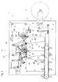
- FIG. 1 shows an FFS machine, which is suitable for forming, filling and closing of sacks and to which the teaching of the present document can be advantageously applied.
- This device 1 comprises a support arm 2, on which a winding 3 with tubular film 4 rests.
- the tubular film 4 has in FIG. 1 not shown gussets 41.
- the transport rollers 5, which may also be driven in part, provide for a generally continuous development of the tubular film 4.
- the acted upon by a piston-cylinder unit 10 with a load lever 9, which carries a guide roller 6 and a total of often Dancer device is called, and the feed roller 7, 8 and the feed roller pair 15 provide a total of known per se for the fact that the tubular film 4 is intermittently moved on their further transport cycle intermittently.
- the transport roller 8a is part of a register device 29, with which the length of the transport path of the tubular film 4 to the Format of the later bags can be adjusted.
- the transport roller 8a is arranged relative to the device 1 so as to be displaceable.
- To move is a manual or electric motor operated and known per se spindle drive available.
- the tubular film 4 is pushed through the welding jaws 33 of a transverse welding station 13 and through a cross-cutting station 16.
- the tools of the transverse welding station 13 and the cross cutting station 16 can be moved in a manner not described in detail, for example by a parallelogram 14, in planes orthogonal to the feed direction of the tubular film 4 to and from this.
- a piece of tubing 18 is separated from the tubular film 4 above the gripper 17 in the cross-cutting station 16.
- a transverse weld 42 is attached, which represents the bottom or the head side of the hose piece 18 to be formed in the next working cycle of the device 1. Accordingly, 13 head seams are generated in the transverse welding station.
- the manufacture of the head or bottom seams may not only be effected by transverse welding, although preferably, but also other joining methods, such as gluing, are conceivable.
- the grippers 17 convey the hose piece 18 to a transfer point at which further grippers 19 grasp the hose pieces 18 and transport them to a filling station 20. There, the tube piece 18 is transferred to stationary gripper 21 and opened by the suckers 22, so that the contents, which is passed through the filler neck 23, can get into the tube piece 18.
- the tube piece 18 rests with its lower end on a conveyor belt 24, so that the hose piece 18 is not excessively loaded along its longitudinal edges during the filling process.
- Further grippers 25 convey the filled tube piece to the head or bottom seam welding station 26, in which the tube piece 18 is closed with a top or bottom weld seam and thus forms a finished bag 27. Also, the closing of the tube piece 18 in its head area can be done by a different joining method.
- the finished bag 27 is guided out of the device 1 by the conveyor belt 24. Here, the bag 27 is usually much higher (in the y-direction) than wide (in the x-direction).
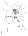
- FIG. 2 shows a transverse welding station 16, which can also simultaneously separate a plastic web or tubular film web 4 transversely.
- a transverse welding station 16 which can also simultaneously separate a plastic web or tubular film web 4 transversely.
- the plastic web 4 can be conveyed by a feed roller pair 15 in the web running direction z. After the preferred roller pair 15, the web comes into the working area of the holding means 100, 101, which have a movable part 100 and a counter-layer 101.
- a Kunststoffschlauchleitelement 104 is attached via the support rod with coil spring 108 to the movable part 100 of the holding means. The function of these device components will be explained below.
- the welding jaws 102 and 103 which are each hinged to one of the tool carriers 119 and 120 and which together with these components form the welding device 118, follow the first holding means 100, 101 in the plastic hose transport direction z.
- the tool carrier 120 and the knife 105 is attached, while the tool carrier 119 carries the active part 106 of a further holding means 107, 106, 107, 106 also include the counter-layer 107 of the holding means.
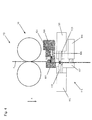
- FIG. 3 is a work situation to see in which the movable part 100 of the holding means 100, 101 has carried out a movement along the arrow 121, so that the film 4 is held by the holding means 100, 101.
- the Kunststoffschlauchleitelement 104 has moved to its working position. Here it deflects the film 4 and presses it against the counter-position 101 of the holding means. The resulting pressure is determined by the helical spring associated with the support rod, since the support rod 108 in the direction x transversely to the transport direction z is slidably mounted on the movable part 100 of the holding means.
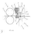
- FIG. 4 is the result of another work step shown.
- the welding jaws 102, 103, the knife 105 and the holding means 106, 107 reaches their working positions.
- the plastic sheet is held by holding means 106, 107, the cross cutting cut is performed and the welding process begins.
- the welding process may be the process that consumes the most time since the heat transferred from the outside to the tubular film web must first be transported through the plastic layers.
- FIG. 5 Therefore, the situation after the next step is shown: the movable part of the holding means 100 and the backstop 101 of the holding means have been moved apart. Also, the Kunststoffschlauchleitelement 104 has by this movement no longer contact with the tubular film web 4. Therefore, the shortest possible Schlauchfolienbahnweg in FIG. 5 shorter than in the Figures 3 and 4 in which it is shown how the Schlauchfolienleitelement 104 extends the web path. For the reasons mentioned arises in the situation according to FIG. 5 a loose in the area between the welding jaws 102, 103 and the feed roller pair 15, which serves as a holding means in this situation.
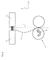
- FIGS. 6 to 9 show schematically illustrated welding stations 26. Despite the schematic representation of simpler stations - which must be presented hardly more complicated than the sketches in the FIGS. 6 to 9 - often used on FFS machines as top seam welding station 26.
- FIG. 6 is to indicate that the shortest possible distance of the tubular film web or the distance between the holding means 110 and 111 and the welding jaws 103, 102 can be reduced by these device components along the transport direction z are moved towards each other (indicated by the arrows 122, 123) ,
- This relative movement between welding jaws 103, 102 and holding means is usually caused by a movement of one of the two functional units - relative to the rest of the machine to the other functional unit - to. If such a movement is brought about while both the welding jaws and the holding means are closed, a loose or tension-free web section 112 (loose) is created, which again helps to prevent damage in the area of the weld seam.
- FIG. 7 the lots are brought about by a relative movement of the two functional units transversely to the web transport direction z (arrow 113).
- FIG. 8 For example, a welding station is shown in which a plastic tubing member 104 is initially in contact with the web 4 and provides a shortest possible pathway that is longer than the actual distance between the hold line of the support means 110, 111 and the location where the weld is made.
Landscapes
- Engineering & Computer Science (AREA)
- Mechanical Engineering (AREA)
- Lining Or Joining Of Plastics Or The Like (AREA)
- Containers And Plastic Fillers For Packaging (AREA)
Abstract
Description
- Die Erfindung betrifft ein Verfahren zum Querschweißen von Kunststoffschläuchen und eine Vorrichtung zum Formen und Schließen von Säcken. Es sind verschiedene Verfahren zur Sackproduktion bekannt, bei denen von einem Kunststoffschlauch ausgegangen wird und Querschweißnähte in den Schlauch oder in die Schlauchstücke eingebracht werden.
- Zu diesen Sackherstellverfahren zählen auch Verfahren zur Herstellung und Befüllung derselben. Maschinen, die verschließbare und verschlossene Verpackungsmittel wie Säcke herstellen und befüllen, werden FFS-Maschinen (Form, Fill and Seal-Maschinen) genannt. Jedoch sind die Arbeitsweise und die Leistungsfähigkeit dieser Maschinen in den verschiedenen Technikbereichen sehr unterschiedlich. Wenn als Ausdruck von Leistungsfähigkeit die Menge und die Masse der pro Zeiteinheit hergestellten und befüllten Verpackungsmittel herangezogen wird, dann nehmen in diesem Zusammenhang FFS-Maschinen zur Abfüllung von industriellen Schüttgütern, wie sie in der
DE 10 2004 034 489 A1 , derEP 1 201 539 B1 oder derEP 1 623 926 A2 beschrieben werden, eine führende Rolle ein. - Mit derartigen Maschinen ist es möglich, mehr als 2.000 Säcke in der Stunde mit granulatartigem Schüttgut zu befüllen und die Säcke zu verschließen. Viele dieser Säcke wiegen 25 kg und mehr. Die vorgenannten FFS-Maschinen führen in der Regel folgende Verfahrensschritte zur Bildung, Befüllung und zum Verschließen der Säcke durch:
- flachgelegtes schlauchförmiges Kunststoffmaterial, das eine Hauptsymmetrieachse und zwei dazu parallele Schlauchränder aufweist, wird in Richtung der Hauptsymmetrieachse des Schlauches von einer Rolle abgewickelt;
- das schlauchförmige Material wird durch einen Schweiß- und Trennvorgang mit einer ersten zur Schlauchachse senkrechten Querschweißnaht versehen und entlang einer parallel zu dieser Querschweißnaht verlaufenden Trennlinie getrennt, so dass einseitig offene vereinzelte Schlauchstücke entstehen;
- die einseitig offenen Schlauchstücke werden in der Abfüllstation mit der Schwerkraft durch ihr noch offenes Ende mit einem Füllmaterial befüllt,
- das noch offene Ende der einseitig offenen Schlauchstücke wird mit einer zweiten Schweißnaht, die ebenfalls senkrecht zur Schlauchachse verläuft, versehen.
- Zu den Charakteristika dieser Maschinen zählt der erwähnte Querschweißvorgang, bei dem Schweißbacken Verwendung finden und bei dem oft eine Querschweißnaht ausgeprägt wird, die über die gesamte Breite des Schlauches beziehungsweise des Schlauchstückes reicht.
- In jüngerer Zeit werden unter anderem in der Sackproduktion Kunststoffmaterialien verwendet, die verstreckt oder gereckt sind. Bei diesen Materialien wird entweder direkt nach ihrer Extrusion (verstrecken) oder später (recken) ein Auseinanderziehen des Kunststoffmaterials vorgenommen. Dieser Vorgang führt später bei dem später erkalteten Material in der "Ziehrichtung" zu großer Zugfestigkeit, was bedeutet, dass mit weniger Verpackungsmaterial die gleiche Menge an Säcken hergestellt werden kann. Zu diesen (Kunststoff-)Materialien gehört zunächst das ganze klassische Folienmaterial unter Einschluss der Polyolefine, da diese Materialien oft unter Einbringung von Reckverhältnissen (z.B, im Blas- oder Giesfolienverfahren) hergestellt werden. Die Effekte des Reckens oder Verstreckens sind insbesondere bei Polyalkylen, wie Polyethylen oder Polypropylen ausgeprägt.
- In jüngerer Zeit gewinnt die so genannte MDO-Folie (Machine Direction Orientation), also Folie, die nach ihrer Extrusion von einem speziellen Reckwerk gereckt wird, an Boden. Als sehr stark gerecktes Material ist in diesem Zusammenhang auch Gewebe aus gerecktem Polyolefinmaterial zu nennen. Ebenfalls in jüngerer Zeit wird auch Vliesmaterial zur Sackproduktion verwendet. Auch bei den Vliesfasern selber liegen oft hohe Reckbeziehungsweise Verstreckverhältnisse vor. Dies gilt natürlich auch, wenn Materialien Verwendung finden, die Schichten aus verschiedenen Materialien aufweisen (z. B. Laminate aus Folien und Gewebe, beschichtetes Gewebe, Folie und Vlies usw.). Den genannten Materialien ist gemein, dass sie künstlich hergestellt sind und dass sie zur Sackherstellung ähnlich wie Folien genutzt werden. Daher werden die Begriffe Kunststoff und Folie in dieser Druckschrift auch häufig synonym gebraucht.
- Bedauerlicherweise zeigt die Erfahrung, dass sich gerade bei Materialien, die eine starke Reckung oder Verstreckung erfahren haben, Querschweißnähte befriedigender Qualität schwer herstellen lassen.
- Daher besteht die Aufgabe der vorliegenden Erfindung darin, ein Verfahren zum Querschweißen von Kunststoffschläuchen und eine Vorrichtung zum Formen, Füllen und Verschließen von Säcken vorzuschlagen, mit denen sich Querschweißnähte guter Qualität bei hoher Fertigungsgeschwindigkeit herstellen lassen.
- Die Aufgabe wird gelöst durch die Ansprüche 1 und 12.
- Die vorliegende Erfindung schlägt vor, dass in die Kunststoffschlauchwegstrecke zwischen der Haltelinie und dem Ort, an dem die Querschweißnaht hergestellt wird, eine Lose eingebracht wird, bevor der Schweißprozess abgeschlossen ist.
- In dem vorliegenden Zusammenhang ist eine Haltelinie eine Linie, die sich ausprägt, weil das spätere Schlauchmaterial gehalten wird. Die Haltemittel können zangenartig ausgeprägt sein, wobei oft zwei Balken die Kunststoffschlauchbahn über ihre Breite "in die Zange nehmen" werden. Eine andere Alternative besteht in der Verwendung von zumindest einer Walze, die an dem "In-die-Zange-Nehmen" beteiligt sein kann. Oft wird hierzu ein Walzenpaar, das auch als Vorzugswalzenpaar verwendet werden kann, eingesetzt werden. Die Haltemittel halten die Bahn in der Regel während des Schweißprozesses. Eine zusätzliche Haltefunktion kann jedoch auch von den Schweißbacken ausgeübt werden, während diese in Kontakt mit der Bahn stehen. In der Regel wird ein solcher Schweißprozess damit einhergehen, dass die Schweißbacken den Kunststoffschlauch in die Zange nehmen und dabei einen Temperatureintrag von außen auf den Schlauch vornehmen.
- Die betreffende Wärmeenergie durchdringt in einer gewissen Zeitspanne das Kunststoffmaterial und bewirkt schließlich an der späteren Schweißstelle, an der die beiden Schlauchwandungen miteinander stoßen und zusammengedrückt werden, den gewünschten thermischen Fügeprozess.
- Der letztgenannte Begriff "thermischer Fügeprozess" ist bewusst sehr vorsichtig gewählt worden:
- Es ist gerade der Wärmeeintrag, der die eingangs geschilderten Qualitätseinbußen der Schweißnaht hervorruft. Aus diesem Grund kann die eigentliche Querschweißung auch nur eine Siegelung (die schon bei etwas geringeren Temperaturen zustande kommt) oder z. B. ein thermisch induzierter Klebeprozess sein (z. B. Hotmelt ist auf den Bereich der späteren Naht aufgetragen und wird durch die Wärme aktiviert). Alle denkbaren thermischen Fügeprozesse werden hier zunächst pauschalierend als "Schweißen" zusammengefasst.
- Zu diesen thermischen Fügeprozessen gehört auch das Ultraschallschweißen, bei dem in der Regel eine Schwingung mit einer Frequenz im Ultraschallbereich an der "Schweißstelle" in Wärmeenergie umgesetzt wird und den thermischen Fügeprozess bewirkt.
- Eine Lose ist für die Zwecke der vorliegenden Anmeldung ein Schlauchbahnabschnitt, der nicht der üblichen Bahnspannung unterliegt. Die übliche Bahnspannung wird in vielen Maschinen, die Kunststoffschläuche verarbeiten, von Vorzügen (oft Vorzugswalzenpaare) und Abwicklungen bestimmt. Dies ist auch bei den FFS-Maschinen nach den vorgenannten Druckschriften der Fall. Allerdings wird gerade bei diesen Maschinen die Bahnspannung im Bereich der Schweißnahterzeugung zunächst von der Erdbeschleunigung und dem Sackgewicht bestimmt, da das Schlauchende oder der Schlauchabschnitt unter den Schweißstationen frei hängen.
- In dem Bereich zwischen den Vorzugswalzen und dem Ort, an dem die Querschweißnaht hergestellt wird, wird diese Bahnspannung quasi "eingefroren", nachdem die Schweißbacken in Kontakt mit der Kunststoffschlauchbahn gekommen sind und die Bahn durch ihre Zangenbewegung fixieren. Dies gilt erst recht, wenn irgendwelche weiteren Haltemittel in dem Bereich zwischen den Vorzugswalzen und den Schweißbacken auf die Bahn einwirken.
- Eine Lose wird demzufolge eingebracht, wenn die erwähnte Bahnspannung - insbesondere bewusst - in dem Bereich zwischen irgendwelchen Haltemitteln und dem Wirkungsort der Schweißbacken herabgesetzt wird (hier Kunststoffschlauchwegstrecke zwischen der Haltelinie und dem Ort, an dem die Querschweißung eingebracht wird).
- Dies kann in dem geschilderten speziellen Fall geschehen, indem die Abzugswalzen weiter Kunststoffschlauchmaterial fördern, wenn die Schweißbacken oder ein ihnen in Kunststoffschlauchtransportrichtung nachgelagertes Haltemittel bereits geschlossen sind. In diesem Fall entsteht die Lose, da das in den abgegrenzten Bereich geförderte Material in Folge der andauernden Förderung eine größere Länge hat als die Wegstrecke zwischen den Haltemitteln und dem Wirkungsort der Schweißbacken. Eine weitere Alternative oder Ergänzung kann in diesem Zusammenhang darin bestehen, neben dem Haltemittel, das in der Schlauchfolienbahntransportrichtung den Schweißbacken vorgelagert ist, noch ein weiteres den Schweißbacken nachgelagertes Haltemittel vorzusehen. Auch ein Schließen des letzten nachgelagerten Haltemittels kann die Bahnspannung - insbesondere wenn noch Schlauchfolienmaterial gefördert wird - herabsetzen.
- Alternativ oder ergänzend kann die Wegstrecke zwischen den den Schweißbacken vorgelagerten Haltemitteln und den Schweißbacken verringert werden. Hierzu kann eine Relativbewegung zwischen den Schweißbacken und den Haltemitteln vorgenommen werden. Eine zweite Möglichkeit zur Verringerung der für den Kunststoffschlauch kürzest möglichen Wegstrecke besteht in der Änderung der Position von Kunststoffschlauchleitelementen, die eine kürzere Wegstrecke freigibt und so eine Lose schafft.
- Es ist vorteilhaft, wenn die in dieser Druckschrift beschriebenen und beanspruchten Verfahren durchgeführt werden, indem die Steuervorrichtung zu ihrer automatischen Abarbeitung eingerichtet wird. Dies kann durch das Programmieren der Steuervorrichtung geschehen.
- Weitere Ausführungsbeispiele der Erfindung gehen aus der gegenständlichen Beschreibung und den Ansprüchen hervor.
- Die einzelnen Figuren zeigen:
- Fig. 1
- Die Seitenansicht einer FFS-Maschine
- Fig. 2
- Eine erste Querschweißstation in einer ersten Arbeitssituation
- Fig. 3
- Die erste Querschweißstation in einer zweiten Arbeitssituation
- Fig. 4
- Die erste Querschweißstation in einer dritten Arbeitssituation
- Fig. 5
- Die erste Querschweißstation in einer vierten Arbeitssituation
- Fig. 6
- Eine zweite Querschweißstation
- Fig. 7
- Eine dritte Querschweißstation
- Fig. 8
- Eine vierte Querschweißstation
- Fig. 9
- Eine fünfte Querschweißstation
- Die
Figur 1 zeigt eine FFS-Maschine, die zum Formen, Füllen und Schließen von Säcken geeignet ist und auf die sich die Lehre der vorliegenden Druckschrift vorteilhaft anwenden lässt. Diese Vorrichtung 1 umfasst einen Tragarm 2, auf welchem ein Wickel 3 mit schlauchförmiger Folie 4 aufliegt. Die schlauchförmige Folie 4 weist inFigur 1 nicht dargestellte Seitenfalten 41 auf. Die Transportwalzen 5, die zum Teil auch angetrieben sein können, sorgen für eine in der Regel kontinuierliche Abwicklung der schlauchförmigen Folie 4. Der durch eine Kolben-Zylinder-Einheit 10 mit einer Last beaufschlagte Hebel 9, welcher eine Umlenkwalze 6 trägt und insgesamt häufig als Tänzereinrichtung bezeichnet wird, und die Transportwalze 7, 8 und das Vorschubrollenpaar 15 sorgen insgesamt auf an sich bekannte Weise dafür, dass die schlauchförmige Folie 4 auf ihrem weiteren Transportweg taktweise intermittierend weiterbewegt wird. Die Transportwalze 8a ist Bestandteil einer Registervorrichtung 29, mit welcher die Länge des Transportweges der schlauchförmigen Folie 4 an das Format der späteren Säcke angepasst werden kann. Dazu ist die Transportwalze 8a relativ zur Vorrichtung 1 verschieblich angeordnet. Zum Verschieben steht ein händisch oder elektromotorisch betriebener und an sich bekannter Spindeltrieb zur Verfügung. - Mit dem Vorschubrollenpaar 15 wird die schlauchförmige Folie 4 durch die Schweißbacken 33 einer Querschweißstation 13 und durch eine Querschneidestation 16 hindurch geschoben. Die Werkzeuge der Querschweißstation 13 und der Querschneidestation 16 können auf nicht näher beschriebene Weise, beispielsweise durch eine Parallelogrammanordnung 14, in Ebenen orthogonal zur Vorschubrichtung der schlauchförmigen Folie 4 auf diese zu und von dieser weg bewegt werden. Nachdem die Greifer 17 die schlauchförmige Folie 4 ergriffen haben, wird oberhalb der Greifer 17 ein Schlauchstück 18 in der Querschneidestation 16 von der schlauchförmigen Folie 4 abgetrennt. Zeitgleich wird oberhalb der Schnittkante an der schlauchförmigen Folie 4 in der Querschweißstation 13 eine Querschweißung 42 angebracht, welche den Boden oder die Kopfseite des im nächsten Arbeitstakt der Vorrichtung 1 zu bildenden Schlauchstücks 18 darstellt. Dementsprechend werden in der Querschweißstation 13 Kopfnähte erzeugt. Allgemein kann die Herstellung der Kopf- oder Bodennähte jedoch nicht nur, auch wenn vorzugsweise, durch eine Querschweißung erfolgen, sondern es sind auch weitere Fügeverfahren, etwa das Kleben, denkbar.
- Die Greifer 17 befördern das Schlauchstück 18 zu einem Übergabepunkt, an dem weitere Greifer 19 das Schlauchstücke 18 erfassen und zu einer Füllstation 20 transportieren. Dort wird das Schlauchstück 18 an stationäre Greifer 21 übergeben und von den Saugern 22 geöffnet, so dass das Füllgut, welches durch den Füllstutzen 23 geleitet wird, in das Schlauchstück 18 gelangen kann. Das Schlauchstück 18 liegt dabei mit seinem unteren Ende auf einem Transportband 24 auf, so dass das Schlauchstück 18 während des Befüllvorganges nicht übermäßig entlang seiner Längskanten belastet wird. Weitere Greifer 25 befördern das befüllte Schlauchstück zur Kopf- oder Bodennahtschweißstation 26, in der das Schlauchstück 18 mit einer Kopf- bzw. Bodenschweißnaht verschlossen wird und so einen fertigen Sack 27 bildet. Auch das Verschließen des Schlauchstücks 18 in seinem Kopfbereich kann durch ein anderes Fügeverfahren erfolgen. Der fertige Sack 27 wird von dem Transportband 24 aus der Vorrichtung 1 heraus geführt. Hierbei ist der Sack 27 in der Regel sehr viel höher (in y-Richtung) als breit (in x-Richtung).
-
Figur 2 zeigt eine Querschweißstation 16, die gleichzeitig auch eine Kunststoffbahn oder Schlauchfolienbahn 4 quer trennen kann. Eine solche Station kommt oft in FFS-Maschinen zum Einsatz. Die Kunststoffbahn 4 kann durch ein Vorzugswalzenpaar 15 in der Bahnlaufrichtung z gefördert werden. Nach dem Vorzugswalzenpaar 15 kommt die Bahn in den Arbeitsbereich der Haltemittel 100, 101, die einen beweglichen Teil 100 und eine Gegenlage 101 aufweisen. In dem gezeigten Ausführungsbeispiel ist auch ein Kunststoffschlauchleitelement 104 über die Haltestange mit Spiralfeder 108 an dem beweglichen Teil 100 der Haltemittel angebracht. Die Funktion dieser Vorrichtungsbestandteile wird weiter unten erklärt. - In der Kunststoffschlauchtransportrichtung z folgen auf die in Kunststoffschlauchtransportrichtung z ersten Haltemittel 100, 101 die Schweißbacken 102 und 103, die jeweils an einen der Werkzeugträger 119 und 120 angelenkt sind und mit diesen Bestandteilen die Schweißvorrichtung 118 bilden. An dem Werkzeugträger 120 ist auch das Messer 105 angebracht, während der Werkzeugträger 119 den aktiven Teil 106 eines weiteren Haltemittels 107, 106 trägt, die 107, 106 auch noch die Gegenlage 107 des Haltemittels umfassen. Die Funktion all dieser Elemente wird nun mit Blick auf die
Figuren 3 bis 5 erklärt, die eine Abfolge von Arbeitsschritten der beschriebenen Station 15 zeigen. - In
Figur 3 ist eine Arbeitssituation zu sehen, in der der bewegliche Teil 100 der Haltemittel 100, 101 eine Bewegung entlang des Pfeiles 121 ausgeführt hat, so dass die Folie 4 durch die Haltemittel 100, 101 gehalten wird. In dieser Situation ist auch das Kunststoffschlauchleitelement 104 in seine Arbeitsstellung gefahren. Hier lenkt es die Folie 4 um und drückt sie gegen die Gegenlage 101 des Haltemittels. Der dabei entstehende Druck wird durch die der Haltestange zugeordnete Spiralfeder bestimmt, da die Haltestange 108 in der Richtung x quer zur Transportrichtung z verschieblich an dem beweglichen Teil 100 des Haltemittel angebracht ist. - In
Figur 4 ist das Ergebnis eines weiteren Arbeitsschritts gezeigt. Durch eine Bewegung der beiden Werkzeugträger 119, 120 und des aktiven Teils der Haltemittel 106 auf die Kunststoffbahn zu, sind die Schweißbacken 102, 103 das Messer 105 sowie die Haltemittel 106, 107 in ihre Arbeitspositionen gelangt. - Als Folge wird die Kunststoffbahn durch Haltemittel 106, 107 gehalten, der Quertrennschnitt wird durchgeführt und der Schweißprozess beginnt.
- Der Schweißprozess dürfte in diesem Zusammenhang derjenige Prozess sein, der am meisten Zeit verschlingt, da die von außen auf die Schlauchfolienbahn übertragene Wärme zunächst durch die Kunststoffschichten transportiert werden muss.
- In
Figur 5 ist daher die Situation nach dem nächsten Arbeitsschritt dargestellt: der bewegliche Teil des Haltemittel 100 und die Gegenlage 101 des Haltemittels sind auseinander bewegt worden. Auch das Kunststoffschlauchleitelement 104 hat durch diese Bewegung keinen Kontakt mehr zu der Schlauchfolienbahn 4. Daher ist der kürzest mögliche Schlauchfolienbahnweg inFigur 5 kürzer als in denFiguren 3 und4 , in denen gezeigt ist, wie das Schlauchfolienleitelement 104 den Bahnweg verlängert. Aus den genannten Gründen entsteht bei der Situation gemäßFigur 5 eine Lose im Bereich zwischen den Schweißbacken 102, 103 und dem Vorzugswalzenpaar 15, das in dieser Situation als Haltemittel dient. - Durch diese Lose ist es möglich, dass die im Bereich der Schweißbacken 102, 103 mittlerweile durch und durch erhitzte Kunststoffbahn auch dann spannungsfrei bleibt, wenn das gereckte Material im Bereich der Temperatureinwirkung schrumpft. Schäden an dem Kunststoffmaterial 4 werden im Bereich der Schweißung auf diese Weise verhindert.
- In der Regel wird es zu dem genannten Zweck erforderlich sein, die Lose in den Schlauchfolienabschnitt einzubringen, nachdem die Haltemittel 15, 100, 101, 106, 107 begonnen haben, die Schlauchfolienbahn zu halten und bevor die Schweißbacken 102, 103 die zum Schweißen nötige Wärme auf die Schlauchfolienbahn übertragen haben und schließlich geöffnet werden.
- Ein weiterer sinnvoller Startzeitpunkt für den Beginn des Einbringens der Lose 112, 116 ist wie erwähnt der Beginn des Kontakts zwischen Schweißbacken 102, 103 und Kunststoffschlauchbahn 4, da auch die Schweißbacken die Bahn 4 halten können.
- Die
Figuren 6 bis 9 zeigen schematischer dargestellte Schweißstationen 26. Trotz der schematischen Darstellungsweise kommen einfachere Stationen - die kaum komplizierter dargestellt werden müssen als die Skizzen in denFiguren 6 bis 9 - oft an FFS-Maschinen als Kopfnahtschweißstation 26 zum Einsatz. - Die Schweißstationen 26 besitzen Schweißbacken 102, 103 und Haltemittel 110 und 111. Durch
Figur 6 soll angedeutet werden, dass die kürzest mögliche Wegstrecke der Schlauchfolienbahn oder der Abstand zwischen den Haltemitteln 110 und 111 sowie den Schweißbacken 103, 102 verringert werden kann, indem diese Vorrichtungsbestandteile entlang der Transportrichtung z aufeinander zu bewegt werden (angedeutet durch die Pfeile 122, 123). Diese Relativbewegung zwischen Schweißbacken 103, 102 und Haltemitteln wird in der Regel durch eine Bewegung einer der beiden Funktionseinheiten - relativ zum Rest der Maschine auf die andere Funktionseinheit zu - herbeigeführt werden. Wird eine solche Bewegung herbeigeführt, während sowohl die Schweißbacken als auch die Haltemittel geschlossen sind, entsteht ein loser oder spannungsfreier Bahnabschnitt 112 (Lose), der wieder hilft, Schäden im Bereich der Schweißnaht zu vermeiden. - In
Figur 7 wird die Lose durch eine Relativbewegung der beiden Funktionseinheiten quer zur Bahntransportrichtung z herbeigeführt (Pfeil 113). InFigur 8 ist eine Schweißstation gezeigt, bei der zunächst ein Kunststoffschlauchleitelement 104 in Kontakt zu der Bahn 4 steht und einen kürzest möglichen Bahnweg herbeiführt, der länger ist als der eigentliche Abstand zwischen der Haltelinie der Haltemittel 110, 111 und dem Ort, an dem die Schweißung entsteht. - Wenn nun zunächst die Haltemittel 110, 111 und die Schweißbacken 102, 103 in ihre die Bahn 4 haltende Arbeitsstellung gebracht werden und dann das Kunststoffschlauchleitelement 104 quer zur Bahn aus der Kontaktstellung mit der Bahn herausgefahren wird, ergibt sich wieder die benötigte Lose 112.
- In
Figur 9 wird eine solche Lose herbeigeführt, in dem das Vorzugwalzenpaar 15 noch Kunststoffschlauchbahnen in Richtung auf die Schweißbacken fördert, nachdem diese geschlossen sind. Im weiteren Verlauf der Schweißung kann das Vorzugswalzenpaar auch als Haltemittel dienen.Bezugszeichenliste 1 Vorrichtung zum Herstellen und Befüllen von Säcken 2 Tragarm 3 Wickel 4 Folie /Schlauchförmige Folie / Kunststoffschlauch 5 Transportwalze 6 Umlenkwalze 7 Transportwalze 8 , 8a Transportwalze 9 Hebel 10 Kolben-Zylinder-Einheit 11 12 13 Querschweißstation 14 Parallelogrammanordnung 15 Vorschubrollenpaar 16 Querschneide- und Querschweißstation 17 Greifer 18 Schlauchstück 19 Greifer 20 Füllstation 21 Stationärer Greifer 22 Sauger 23 Füllstutzen 24 Transportband 25 Greifer 26 Kopf- oder Bodennahtschweißstation 27 Sack 28 29 Registervorrichtung 30 , 32 Werkzeugträger 33 Schweißbacken 42 Querschweißnaht 58 Stützfläche 59 Gestrichelte Linie "Höhe (y) Sacköffnung" 61 Pfeil Abstand Öffnung 62 des Schlauchstückes 18 zur Stützfläche 58 in vertikaler Richtung 70 Symmetrielinie des Abfüllstutzens 23 72 Rüttler 100 Beweglicher Teil des Haltemittels 101 Gegenlage des Haltemittels 102 Schweißbacken 103 Schweißbacken 104 Kunststoffschlauchleitelement 105 Messer 106 Aktiver Teil des Haltemittels 107 Gegenlage des Haltemittels 108 Haltestange mit Spiralfeder 109 110 Haltemittel 111 Haltemittel 112 loser Bahnabschnitt 113 Pfeil in Bewegungsrichtung der Haltemittel 110, 111 114 Umgeleiteter Bahnabschnitt 115 Abstand 116 Entspannter Bahnabschnitt 117 Bewegungsrichtung des Kunststoffschlauchleitelements 118 Schweißvorrichtung 119 Werkzeugträger 120 Werkzeugträger 121 Pfeil 122 Pfeil Bewegungsrichtung der Haltemittel 123 Pfeil Bewegungsrichtung der Schweißbacken 124 Pfeil Drehrichtung der Abzugswalze
Claims (15)
- Verfahren zum Querschweißen von Kunststoffschläuchen (4),- bei dem zumindest eine Schweißbacke (102, 103) eingesetzt wird, um die Querschweißnaht herzustellen,- bei dem zumindest ein Haltemittel (15, 100, 101, 106, 107, 110, 111) eingesetzt wird, um die Kunststoffschlauchbahn entlang einer Haltelinie zu halten,- wobei sich zwischen der Haltelinie und dem Ort, an dem die Querschweißnaht hergestellt wird, eine Kunststoffschlauchwegstrecke erstreckt,
dadurch gekennzeichnet, dass
in die Kunststoffschlauchwegstrecke zwischen der Haltelinie und dem Ort, an dem die Querschweißnaht hergestellt wird, eine Lose (112, 116) eingebracht wird, bevor der Schweißprozess abgeschlossen ist. - Verfahren nach Anspruch 1,
dadurch gekennzeichnet, dass
die Lose (112, 116) gebildet wird, indem Kunststoffschlauchmaterial (4) in die Kunststoffschlauchwegstrecke zwischen der Haltelinie und dem Ort, an dem die Querschweißnaht hergestellt wird, eingebracht wird, nachdem die Schweißbacken (102, 103), die die Querschweißung vornehmen, in Kontakt mit der Kunststoffschlauchbahn (4) gekommen sind. - Verfahren nach Anspruch 2,
dadurch gekennzeichnet, dass
als Haltemittel (15, 100, 101, 106, 107, 110, 111) ein Walzenpaar (15) eingesetzt wird und dass der Transport des Kunststoffmaterials (4) in die Kunststoffschlauchwegstrecke zwischen der Haltelinie und dem Ort, an dem die Querschweißnaht hergestellt wird, durch eine Förderbewegung (124) zumindest einer Walze des Walzenpaares (15) vorgenommen wird. - Verfahren nach einem der vorstehenden Ansprüche,
dadurch gekennzeichnet, dass
die Lose (112, 116) gebildet wird, indem die kürzest mögliche Kunststoffschlauchwegstrecke zwischen der Haltelinie und dem Ort, an dem die Querschweißnaht hergestellt wird, verringert wird, nachdem die Schweißbacken (102,103) in Kontakt mit der Kunststoffschlauchbahn (4) gekommen sind. - Verfahren nach Anspruch 4,
dadurch gekennzeichnet, dass
die kürzest mögliche Kunststoffschlauchwegstrecke zwischen der Haltelinie und dem Ort, an dem die Querschweißnaht hergestellt wird, durch eine Relativbewegung der Haltemittel (15, 100, 101, 106, 107, 110, 111) und der Schweißbacken (102, 103) verringert wird. - Verfahren nach einem der zwei vorstehenden Ansprüche,
dadurch gekennzeichnet, dass
die Relativbewegung durch eine oder mehrere der folgenden Maßnahmen herbeigeführt wird:- eine Bewegung der Schweißbacken (102, 103) und/oder der Haltemittel (15, 100, 101, 106, 107, 110, 111) in der Richtung (x) quer zur Transportrichtung (z) des Kunststoffschlauchs (4),- eine Bewegung der Schweißbacken (102, 103) und/oder der Haltemittel (15, 100, 101, 106, 107, 110, 111) in der Richtung (z) längs zur Transportrichtung (z) des Kunststoffschlauchs (4),
eine Bewegung der Schweißbacken (102, 103) und/oder der Haltemittel (15, 100, 101, 106, 107, 110, 111), die Bewegungskomponenten in den Richtungen (x, z) längs und quer zur Transportrichtung (z) des Kunststoffschlauchs (4) enthält. - Verfahren nach einem der drei vorstehenden Ansprüche,
dadurch gekennzeichnet, dass
die kürzestmögliche Kunststoffschlauchwegstrecke zwischen der Haltelinie und dem Ort, an dem die Querschweißnaht hergestellt wird, verringert wird, indem die Position von Kunststoffschlauchleitelementen (104) im Bereich der vorgenannten Kunststoffschlauchwegstrecke verändert wird. - Verfahren nach dem vorstehenden Anspruch,
dadurch gekennzeichnet, dass
die Bewegung, mit der die Position der Kunststoffschlauchleitelemente (104) verändert wird, im Wesentlichen quer zu der Transportrichtung (z) der Bahn (4) verläuft. - Verfahren einem der vorstehenden Ansprüche,
dadurch gekennzeichnet,- dass erste (15, 100, 101) und zweite (106, 107) Haltemittel verwendet werden,- dass die ersten Haltemittel (15, 100, 101) den Schweißbacken (102, 103) in der Transportrichtung (z) des Schlauchfolienmaterials (4) vorgelagert sind,- und dass die zweiten Haltemittel (106, 107) den Schweißbacken (102, 103) in der Transportrichtung (z) des Schlauchfolienmaterials (4) nachgelagert sind. - Verfahren einem der vorstehenden Ansprüche,
dadurch gekennzeichnet, dass
das Schlauchfolienmaterial (4) in der Transportrichtung (z) des Schlauchfolienmaterials hinter der Schweißnaht durch einen Querschneidevorgang getrennt wird. - Verfahren einem der vorstehenden Ansprüche,
dadurch gekennzeichnet, dass
die Kopf- und/oder die Bodennaht eines FFS-Sackes (27) durch die Querschweißung gebildet wird. - Vorrichtung (1) zum Formen und Verschließen von Säcken (27), mit welcher ein Kunststoffschlauch (4) zu geschlossenen Säcken (27) verarbeitbar ist,- welche (1) zumindest eine Schweißstation (16, 26) zur Erzeugung von Bodennähten und/oder Kopfnähten enthält,- welche von einer Steuervorrichtung steuerbar ist,- wobei die Schweißstation zumindest ein Haltemittel (15, 100, 101, 106, 107, 110, 111) und zumindest einen Schweißbacken (102, 103) aufweist und wobei sich zwischen diesen beiden Elementen (15, 100, 101, 106, 107, 102, 103) eine Kunststoffschlauchwegstrecke erstreckt,
gekennzeichnet durch
Mittel zum Einbringen einer Lose (112, 116) in die Kunststoffschlauchwegstrecke zwischen dem zumindest einen Haltemittel (15, 100, 101, 106, 107, 110, 111) und dem zumindest einen Schweißbacken (102, 103). - Vorrichtung nach dem vorstehenden Anspruch,
dadurch gekennzeichnet, dass
die Mittel zum Einbringen einer Lose (112, 116) in die Kunststoffschlauchwegstrecke Vorrichtungen umfassen, die die Relativposition des zumindest einen Haltemittels (15, 100, 101, 106, 107, 110, 111) und des zumindest einen Schweißbackens (102, 103) zueinander verändern. - Vorrichtung nach einem der vorstehenden Ansprüche,
dadurch gekennzeichnet, dass
die Mittel zum Einbringen einer Lose (112, 116) in die Kunststoffschlauchwegstrecke ein bewegbares Kunststoffschlauchleitelement (104) umfassen. - Vorrichtung nach dem vorstehenden Anspruch,
dadurch gekennzeichnet, dass- als ein erstes Haltemittel (15, 100, 101, 106, 107) zumindest eine Walze vorgesehen ist, der zumindest ein Aktor zugeordnet ist,- und dass die Mittel zum Einbringen einer Lose (112, 116) in die Kunststoffschlauchwegstrecke eine Kette von Befehlen enthält, mit welcher die Steuervorrichtung dazu eingestellt wird,- den Aktor der zumindest einen Walze zum Transport von Folie anzusteuern, nachdem die Schweißbacke (102, 103) und/oder ein zweites Haltemittel (15, 100, 101, 106, 107) den Kunststoffschlauch (4) fixieren.
Applications Claiming Priority (1)
| Application Number | Priority Date | Filing Date | Title |
|---|---|---|---|
| DE102011015491A DE102011015491B3 (de) | 2011-03-29 | 2011-03-29 | Verfahren zum Querschweißen von Kunststoffschläuchen und Vorrichtung zum Formen und Schließen von Säcken |
Publications (3)
| Publication Number | Publication Date |
|---|---|
| EP2505337A2 true EP2505337A2 (de) | 2012-10-03 |
| EP2505337A3 EP2505337A3 (de) | 2016-12-07 |
| EP2505337B1 EP2505337B1 (de) | 2020-08-19 |
Family
ID=45894201
Family Applications (1)
| Application Number | Title | Priority Date | Filing Date |
|---|---|---|---|
| EP12159587.0A Active EP2505337B1 (de) | 2011-03-29 | 2012-03-15 | Verfahren zum Querschweißen von Kunststoffschläuchen und Vorrichtung zum Formen und Schließen von Säcken |
Country Status (3)
| Country | Link |
|---|---|
| EP (1) | EP2505337B1 (de) |
| DE (1) | DE102011015491B3 (de) |
| ES (1) | ES2823976T3 (de) |
Cited By (1)
| Publication number | Priority date | Publication date | Assignee | Title |
|---|---|---|---|---|
| US10501223B2 (en) | 2012-11-07 | 2019-12-10 | Borealis Ag | Sealing oriented films |
Families Citing this family (1)
| Publication number | Priority date | Publication date | Assignee | Title |
|---|---|---|---|---|
| CN112942211B (zh) * | 2021-02-01 | 2022-05-27 | 重庆文理学院 | 一种落叶清扫车 |
Citations (3)
| Publication number | Priority date | Publication date | Assignee | Title |
|---|---|---|---|---|
| EP1201539B1 (de) | 2000-10-24 | 2005-12-21 | WindmÀ¶ller & Hölscher | Vorrichtung zum Herstellen und vorzugsweise auch zum Befüllen und Verschliessen von Säcken aus thermoplastichem Kunststoff |
| EP1623926A2 (de) | 2004-08-04 | 2006-02-08 | Windmöller & Hölscher KG | Vorrichtung und Verfahren zur Herstellung und Befüllung von Säcken |
| DE102004034489A1 (de) | 2004-07-16 | 2006-04-20 | Windmöller & Hölscher Kg | Verfahren und Vorrichtung zur Herstellung und Befüllung von Säcken |
Family Cites Families (14)
| Publication number | Priority date | Publication date | Assignee | Title |
|---|---|---|---|---|
| US2200971A (en) * | 1939-03-04 | 1940-05-14 | Stokes & Smith Co | System for making, filling, and sealing containers |
| FR1397917A (fr) * | 1963-04-12 | 1965-05-07 | Weldotron Corp | Appareil et procédé pour la formation de paquets avec une matière d'emballage soudable à chaud |
| US3287199A (en) * | 1963-10-24 | 1966-11-22 | Triangle Package Machinery Co | Jaw assembly for container forming and filling machine |
| US3553059A (en) * | 1968-12-04 | 1971-01-05 | Anderson Bros Mfg Co | Heat sealing apparatus |
| CA914048A (en) * | 1970-12-29 | 1972-11-07 | M. Groundwater Fergus | Process and apparatus for heat sealing thermoplastic films |
| NL7505838A (nl) * | 1975-05-16 | 1976-11-18 | Meulen Leonard V D | Inrichting voor het dichtlassen en afscheiden (doorsnijden) van een kunststofstrook. |
| DE2612959A1 (de) * | 1976-03-26 | 1977-10-06 | Bosch Gmbh Robert | Maschine zum herstellen, fuellen und verschliessen von schlauchbeuteln |
| DE2629065C3 (de) * | 1976-06-29 | 1979-04-05 | Windmoeller & Hoelscher, 4540 Lengerich | Vorrichtung zum automatischen Füllen und Verschließen von Sacken |
| DE2809515C2 (de) * | 1978-03-06 | 1980-03-27 | Windmoeller & Hoelscher, 4540 Lengerich | Vorrichtung zum Anbringen von Querschweißnähten an aufeinanderliegende Bahnen aus Kunststoffolie |
| JPH07110647B2 (ja) * | 1988-06-28 | 1995-11-29 | 株式会社東京自働機械製作所 | 製袋充填包装装置 |
| DE4022209A1 (de) * | 1990-05-31 | 1991-12-05 | Rovema Gmbh | Verfahren und vorrichtung zum strippen eines schlauchbeutels |
| CA2066068C (en) * | 1992-04-15 | 2004-09-28 | Arnold Edward Perrett | Heat sealing jaw assembly |
| JP3512127B2 (ja) * | 1994-12-23 | 2004-03-29 | 株式会社イシダ | 製袋包装機の横シ−ル機構 |
| US20060096250A1 (en) * | 2004-11-05 | 2006-05-11 | Rennco, Inc. | Packaging device and method |
-
2011
- 2011-03-29 DE DE102011015491A patent/DE102011015491B3/de active Active
-
2012
- 2012-03-15 ES ES12159587T patent/ES2823976T3/es active Active
- 2012-03-15 EP EP12159587.0A patent/EP2505337B1/de active Active
Patent Citations (3)
| Publication number | Priority date | Publication date | Assignee | Title |
|---|---|---|---|---|
| EP1201539B1 (de) | 2000-10-24 | 2005-12-21 | WindmÀ¶ller & Hölscher | Vorrichtung zum Herstellen und vorzugsweise auch zum Befüllen und Verschliessen von Säcken aus thermoplastichem Kunststoff |
| DE102004034489A1 (de) | 2004-07-16 | 2006-04-20 | Windmöller & Hölscher Kg | Verfahren und Vorrichtung zur Herstellung und Befüllung von Säcken |
| EP1623926A2 (de) | 2004-08-04 | 2006-02-08 | Windmöller & Hölscher KG | Vorrichtung und Verfahren zur Herstellung und Befüllung von Säcken |
Cited By (1)
| Publication number | Priority date | Publication date | Assignee | Title |
|---|---|---|---|---|
| US10501223B2 (en) | 2012-11-07 | 2019-12-10 | Borealis Ag | Sealing oriented films |
Also Published As
| Publication number | Publication date |
|---|---|
| DE102011015491B3 (de) | 2012-06-06 |
| EP2505337A3 (de) | 2016-12-07 |
| EP2505337B1 (de) | 2020-08-19 |
| ES2823976T3 (es) | 2021-05-11 |
Similar Documents
| Publication | Publication Date | Title |
|---|---|---|
| DE69603273T2 (de) | Verfahren und vorrichtung zum komprimieren und verpackung von komprimierbaren produkten | |
| DE102009056078B4 (de) | Verfahren und Vorrichtung zur Herstellung von Pinchsäcken sowie Station zur Bildung von Pinchböden | |
| EP3219646B1 (de) | Anlage zum herstellen eines medizinprodukts sowie verfahren zum betreiben einer solchen anlage | |
| EP0399948B1 (de) | Verfahren und Vorrichtung zum kontinuierlichen Herstellen von Packungen | |
| EP3755631B1 (de) | Fülleinrichtung und verfahren zum befüllen von säcken mit jeweils einem unverschlossenen oberen ende | |
| EP2563672B1 (de) | Verfahren und eine vorrichtung zur herstellung und befüllung von verpackungsmitteln | |
| EP2739455B1 (de) | Verfahren und vorrichtung zum herstellen, befüllen und verschliessen von säcken sowie ein sack | |
| EP1773576B1 (de) | Verfahren und vorrichtung zur herstellung und befüllung von säcken | |
| EP3519311A1 (de) | Kunststoffsack, insbesondere ffs-sack, sowie verfahren und vorrichtung zur herstellung und zum befüllen eines sacks | |
| DE3821905C1 (de) | ||
| DE102011015491B3 (de) | Verfahren zum Querschweißen von Kunststoffschläuchen und Vorrichtung zum Formen und Schließen von Säcken | |
| EP3041672B1 (de) | Vorrichtung zur herstellung von säcken | |
| DE102013220512A1 (de) | Verfahren zum Bilden eines Schlauches aus einem Flachbahnmaterial sowie eine Schlauchbildungseinrichtung und ein System zum Herstellen von Beuteln | |
| WO2014108221A1 (de) | Verfahren zum herstellen von säcken | |
| DE102013014732B4 (de) | Verfahren und Vorrichtung zur Herstellung von Kreuzboden-Säcken | |
| EP3126120B1 (de) | Verfahren und vorrichtung zur herstellung von säcken aus einem gewebeschlauch | |
| DE102004038006A1 (de) | Vorrichtung und Verfahren zur Herstellung und Befüllung von Säcken | |
| DE602005001899T2 (de) | Verfahren und Vorrichtung zum Versehen von Grifföffnungen in Beuteln, und Beutel mit zwei Grifföffnungen | |
| DE69005515T2 (de) | Verfahren und Vorrichtung zur Herstellung von Säcken. | |
| EP1597054B1 (de) | Schlauch sowie vorrichtung und verfahren zur herstellung desselben | |
| DE202004021466U1 (de) | Vorrichtung zur Herstellung und Befüllung von Säcken | |
| DE102005018545B4 (de) | Verfahren und System zur Herstellung und Befüllung von Beuteln oder Säcken | |
| DE2630341C2 (de) | Vorrichtung zur Herstellung von Produkten gleichförmiger Größe aus bahnförmigem Folienmaterial, insbesondere von Plastiksäcken | |
| DE2420970A1 (de) | Verfahren zur herstellung von beuteln und vorrichtung zur durchfuehrung des verfahrens | |
| DE102018102369B4 (de) | Folienverpackungsmaschine zum Verpacken von Gegenständen in Luftpolsterfolienverpackungen |
Legal Events
| Date | Code | Title | Description |
|---|---|---|---|
| PUAI | Public reference made under article 153(3) epc to a published international application that has entered the european phase |
Free format text: ORIGINAL CODE: 0009012 |
|
| AK | Designated contracting states |
Kind code of ref document: A2 Designated state(s): AL AT BE BG CH CY CZ DE DK EE ES FI FR GB GR HR HU IE IS IT LI LT LU LV MC MK MT NL NO PL PT RO RS SE SI SK SM TR |
|
| AX | Request for extension of the european patent |
Extension state: BA ME |
|
| PUAL | Search report despatched |
Free format text: ORIGINAL CODE: 0009013 |
|
| AK | Designated contracting states |
Kind code of ref document: A3 Designated state(s): AL AT BE BG CH CY CZ DE DK EE ES FI FR GB GR HR HU IE IS IT LI LT LU LV MC MK MT NL NO PL PT RO RS SE SI SK SM TR |
|
| AX | Request for extension of the european patent |
Extension state: BA ME |
|
| RIC1 | Information provided on ipc code assigned before grant |
Ipc: B29C 65/74 20060101ALN20161103BHEP Ipc: B65B 43/04 20060101ALI20161103BHEP Ipc: B29C 65/02 20060101AFI20161103BHEP Ipc: B29K 23/00 20060101ALN20161103BHEP Ipc: B65B 51/14 20060101ALN20161103BHEP Ipc: B29C 65/78 20060101ALI20161103BHEP Ipc: B65B 51/30 20060101ALI20161103BHEP |
|
| STAA | Information on the status of an ep patent application or granted ep patent |
Free format text: STATUS: REQUEST FOR EXAMINATION WAS MADE |
|
| 17P | Request for examination filed |
Effective date: 20170607 |
|
| RBV | Designated contracting states (corrected) |
Designated state(s): AL AT BE BG CH CY CZ DE DK EE ES FI FR GB GR HR HU IE IS IT LI LT LU LV MC MK MT NL NO PL PT RO RS SE SI SK SM TR |
|
| STAA | Information on the status of an ep patent application or granted ep patent |
Free format text: STATUS: EXAMINATION IS IN PROGRESS |
|
| 17Q | First examination report despatched |
Effective date: 20180614 |
|
| RIC1 | Information provided on ipc code assigned before grant |
Ipc: B65B 43/46 20060101ALI20190923BHEP Ipc: B65B 51/30 20060101ALI20190923BHEP Ipc: B29C 65/74 20060101ALN20190923BHEP Ipc: B29C 65/78 20060101ALI20190923BHEP Ipc: B65B 51/14 20060101ALI20190923BHEP Ipc: B29C 65/48 20060101ALN20190923BHEP Ipc: B29C 65/02 20060101AFI20190923BHEP Ipc: B65B 7/02 20060101ALI20190923BHEP Ipc: B29K 23/00 20060101ALN20190923BHEP Ipc: B29C 65/08 20060101ALN20190923BHEP |
|
| RIC1 | Information provided on ipc code assigned before grant |
Ipc: B29C 65/08 20060101ALN20190927BHEP Ipc: B65B 51/14 20060101ALI20190927BHEP Ipc: B29K 23/00 20060101ALN20190927BHEP Ipc: B65B 7/02 20060101ALI20190927BHEP Ipc: B29C 65/78 20060101ALI20190927BHEP Ipc: B29C 65/02 20060101AFI20190927BHEP Ipc: B29C 65/48 20060101ALN20190927BHEP Ipc: B65B 51/30 20060101ALI20190927BHEP Ipc: B65B 43/46 20060101ALI20190927BHEP Ipc: B29C 65/74 20060101ALN20190927BHEP |
|
| RIC1 | Information provided on ipc code assigned before grant |
Ipc: B29K 23/00 20060101ALN20200304BHEP Ipc: B65B 51/14 20060101ALI20200304BHEP Ipc: B29C 65/48 20060101ALN20200304BHEP Ipc: B29C 65/02 20060101AFI20200304BHEP Ipc: B29C 65/08 20060101ALN20200304BHEP Ipc: B65B 7/02 20060101ALI20200304BHEP Ipc: B29C 65/74 20060101ALN20200304BHEP Ipc: B65B 43/46 20060101ALI20200304BHEP Ipc: B65B 51/30 20060101ALI20200304BHEP Ipc: B29C 65/78 20060101ALI20200304BHEP |
|
| GRAP | Despatch of communication of intention to grant a patent |
Free format text: ORIGINAL CODE: EPIDOSNIGR1 |
|
| STAA | Information on the status of an ep patent application or granted ep patent |
Free format text: STATUS: GRANT OF PATENT IS INTENDED |
|
| RIC1 | Information provided on ipc code assigned before grant |
Ipc: B29K 23/00 20060101ALN20200327BHEP Ipc: B65B 51/14 20060101ALI20200327BHEP Ipc: B29C 65/74 20060101ALN20200327BHEP Ipc: B65B 43/46 20060101ALI20200327BHEP Ipc: B29C 65/78 20060101ALI20200327BHEP Ipc: B29C 65/48 20060101ALN20200327BHEP Ipc: B65B 51/30 20060101ALI20200327BHEP Ipc: B29C 65/02 20060101AFI20200327BHEP Ipc: B29C 65/08 20060101ALN20200327BHEP Ipc: B65B 7/02 20060101ALI20200327BHEP |
|
| INTG | Intention to grant announced |
Effective date: 20200506 |
|
| GRAS | Grant fee paid |
Free format text: ORIGINAL CODE: EPIDOSNIGR3 |
|
| GRAA | (expected) grant |
Free format text: ORIGINAL CODE: 0009210 |
|
| STAA | Information on the status of an ep patent application or granted ep patent |
Free format text: STATUS: THE PATENT HAS BEEN GRANTED |
|
| AK | Designated contracting states |
Kind code of ref document: B1 Designated state(s): AL AT BE BG CH CY CZ DE DK EE ES FI FR GB GR HR HU IE IS IT LI LT LU LV MC MK MT NL NO PL PT RO RS SE SI SK SM TR |
|
| REG | Reference to a national code |
Ref country code: GB Ref legal event code: FG4D Free format text: NOT ENGLISH |
|
| REG | Reference to a national code |
Ref country code: CH Ref legal event code: EP |
|
| REG | Reference to a national code |
Ref country code: DE Ref legal event code: R096 Ref document number: 502012016291 Country of ref document: DE |
|
| REG | Reference to a national code |
Ref country code: AT Ref legal event code: REF Ref document number: 1303450 Country of ref document: AT Kind code of ref document: T Effective date: 20200915 |
|
| REG | Reference to a national code |
Ref country code: IE Ref legal event code: FG4D Free format text: LANGUAGE OF EP DOCUMENT: GERMAN |
|
| REG | Reference to a national code |
Ref country code: LT Ref legal event code: MG4D |
|
| REG | Reference to a national code |
Ref country code: NL Ref legal event code: MP Effective date: 20200819 |
|
| PG25 | Lapsed in a contracting state [announced via postgrant information from national office to epo] |
Ref country code: NO Free format text: LAPSE BECAUSE OF FAILURE TO SUBMIT A TRANSLATION OF THE DESCRIPTION OR TO PAY THE FEE WITHIN THE PRESCRIBED TIME-LIMIT Effective date: 20201119 Ref country code: HR Free format text: LAPSE BECAUSE OF FAILURE TO SUBMIT A TRANSLATION OF THE DESCRIPTION OR TO PAY THE FEE WITHIN THE PRESCRIBED TIME-LIMIT Effective date: 20200819 Ref country code: SE Free format text: LAPSE BECAUSE OF FAILURE TO SUBMIT A TRANSLATION OF THE DESCRIPTION OR TO PAY THE FEE WITHIN THE PRESCRIBED TIME-LIMIT Effective date: 20200819 Ref country code: FI Free format text: LAPSE BECAUSE OF FAILURE TO SUBMIT A TRANSLATION OF THE DESCRIPTION OR TO PAY THE FEE WITHIN THE PRESCRIBED TIME-LIMIT Effective date: 20200819 Ref country code: GR Free format text: LAPSE BECAUSE OF FAILURE TO SUBMIT A TRANSLATION OF THE DESCRIPTION OR TO PAY THE FEE WITHIN THE PRESCRIBED TIME-LIMIT Effective date: 20201120 Ref country code: PT Free format text: LAPSE BECAUSE OF FAILURE TO SUBMIT A TRANSLATION OF THE DESCRIPTION OR TO PAY THE FEE WITHIN THE PRESCRIBED TIME-LIMIT Effective date: 20201221 Ref country code: LT Free format text: LAPSE BECAUSE OF FAILURE TO SUBMIT A TRANSLATION OF THE DESCRIPTION OR TO PAY THE FEE WITHIN THE PRESCRIBED TIME-LIMIT Effective date: 20200819 Ref country code: BG Free format text: LAPSE BECAUSE OF FAILURE TO SUBMIT A TRANSLATION OF THE DESCRIPTION OR TO PAY THE FEE WITHIN THE PRESCRIBED TIME-LIMIT Effective date: 20201119 |
|
| PG25 | Lapsed in a contracting state [announced via postgrant information from national office to epo] |
Ref country code: NL Free format text: LAPSE BECAUSE OF FAILURE TO SUBMIT A TRANSLATION OF THE DESCRIPTION OR TO PAY THE FEE WITHIN THE PRESCRIBED TIME-LIMIT Effective date: 20200819 Ref country code: PL Free format text: LAPSE BECAUSE OF FAILURE TO SUBMIT A TRANSLATION OF THE DESCRIPTION OR TO PAY THE FEE WITHIN THE PRESCRIBED TIME-LIMIT Effective date: 20200819 Ref country code: LV Free format text: LAPSE BECAUSE OF FAILURE TO SUBMIT A TRANSLATION OF THE DESCRIPTION OR TO PAY THE FEE WITHIN THE PRESCRIBED TIME-LIMIT Effective date: 20200819 Ref country code: RS Free format text: LAPSE BECAUSE OF FAILURE TO SUBMIT A TRANSLATION OF THE DESCRIPTION OR TO PAY THE FEE WITHIN THE PRESCRIBED TIME-LIMIT Effective date: 20200819 Ref country code: IS Free format text: LAPSE BECAUSE OF FAILURE TO SUBMIT A TRANSLATION OF THE DESCRIPTION OR TO PAY THE FEE WITHIN THE PRESCRIBED TIME-LIMIT Effective date: 20201219 |
|
| PG25 | Lapsed in a contracting state [announced via postgrant information from national office to epo] |
Ref country code: EE Free format text: LAPSE BECAUSE OF FAILURE TO SUBMIT A TRANSLATION OF THE DESCRIPTION OR TO PAY THE FEE WITHIN THE PRESCRIBED TIME-LIMIT Effective date: 20200819 Ref country code: CZ Free format text: LAPSE BECAUSE OF FAILURE TO SUBMIT A TRANSLATION OF THE DESCRIPTION OR TO PAY THE FEE WITHIN THE PRESCRIBED TIME-LIMIT Effective date: 20200819 Ref country code: DK Free format text: LAPSE BECAUSE OF FAILURE TO SUBMIT A TRANSLATION OF THE DESCRIPTION OR TO PAY THE FEE WITHIN THE PRESCRIBED TIME-LIMIT Effective date: 20200819 Ref country code: RO Free format text: LAPSE BECAUSE OF FAILURE TO SUBMIT A TRANSLATION OF THE DESCRIPTION OR TO PAY THE FEE WITHIN THE PRESCRIBED TIME-LIMIT Effective date: 20200819 Ref country code: SM Free format text: LAPSE BECAUSE OF FAILURE TO SUBMIT A TRANSLATION OF THE DESCRIPTION OR TO PAY THE FEE WITHIN THE PRESCRIBED TIME-LIMIT Effective date: 20200819 |
|
| REG | Reference to a national code |
Ref country code: ES Ref legal event code: FG2A Ref document number: 2823976 Country of ref document: ES Kind code of ref document: T3 Effective date: 20210511 |
|
| REG | Reference to a national code |
Ref country code: DE Ref legal event code: R097 Ref document number: 502012016291 Country of ref document: DE |
|
| PG25 | Lapsed in a contracting state [announced via postgrant information from national office to epo] |
Ref country code: AL Free format text: LAPSE BECAUSE OF FAILURE TO SUBMIT A TRANSLATION OF THE DESCRIPTION OR TO PAY THE FEE WITHIN THE PRESCRIBED TIME-LIMIT Effective date: 20200819 |
|
| PLBE | No opposition filed within time limit |
Free format text: ORIGINAL CODE: 0009261 |
|
| STAA | Information on the status of an ep patent application or granted ep patent |
Free format text: STATUS: NO OPPOSITION FILED WITHIN TIME LIMIT |
|
| PG25 | Lapsed in a contracting state [announced via postgrant information from national office to epo] |
Ref country code: SK Free format text: LAPSE BECAUSE OF FAILURE TO SUBMIT A TRANSLATION OF THE DESCRIPTION OR TO PAY THE FEE WITHIN THE PRESCRIBED TIME-LIMIT Effective date: 20200819 |
|
| 26N | No opposition filed |
Effective date: 20210520 |
|
| PG25 | Lapsed in a contracting state [announced via postgrant information from national office to epo] |
Ref country code: SI Free format text: LAPSE BECAUSE OF FAILURE TO SUBMIT A TRANSLATION OF THE DESCRIPTION OR TO PAY THE FEE WITHIN THE PRESCRIBED TIME-LIMIT Effective date: 20200819 |
|
| PG25 | Lapsed in a contracting state [announced via postgrant information from national office to epo] |
Ref country code: MC Free format text: LAPSE BECAUSE OF FAILURE TO SUBMIT A TRANSLATION OF THE DESCRIPTION OR TO PAY THE FEE WITHIN THE PRESCRIBED TIME-LIMIT Effective date: 20200819 |
|
| REG | Reference to a national code |
Ref country code: CH Ref legal event code: PL |
|
| GBPC | Gb: european patent ceased through non-payment of renewal fee |
Effective date: 20210315 |
|
| REG | Reference to a national code |
Ref country code: BE Ref legal event code: MM Effective date: 20210331 |
|
| PG25 | Lapsed in a contracting state [announced via postgrant information from national office to epo] |
Ref country code: IE Free format text: LAPSE BECAUSE OF NON-PAYMENT OF DUE FEES Effective date: 20210315 Ref country code: GB Free format text: LAPSE BECAUSE OF NON-PAYMENT OF DUE FEES Effective date: 20210315 Ref country code: FR Free format text: LAPSE BECAUSE OF NON-PAYMENT OF DUE FEES Effective date: 20210331 Ref country code: LI Free format text: LAPSE BECAUSE OF NON-PAYMENT OF DUE FEES Effective date: 20210331 Ref country code: LU Free format text: LAPSE BECAUSE OF NON-PAYMENT OF DUE FEES Effective date: 20210315 Ref country code: CH Free format text: LAPSE BECAUSE OF NON-PAYMENT OF DUE FEES Effective date: 20210331 |
|
| PG25 | Lapsed in a contracting state [announced via postgrant information from national office to epo] |
Ref country code: BE Free format text: LAPSE BECAUSE OF NON-PAYMENT OF DUE FEES Effective date: 20210331 |
|
| PG25 | Lapsed in a contracting state [announced via postgrant information from national office to epo] |
Ref country code: HU Free format text: LAPSE BECAUSE OF FAILURE TO SUBMIT A TRANSLATION OF THE DESCRIPTION OR TO PAY THE FEE WITHIN THE PRESCRIBED TIME-LIMIT; INVALID AB INITIO Effective date: 20120315 Ref country code: CY Free format text: LAPSE BECAUSE OF FAILURE TO SUBMIT A TRANSLATION OF THE DESCRIPTION OR TO PAY THE FEE WITHIN THE PRESCRIBED TIME-LIMIT Effective date: 20200819 |
|
| PG25 | Lapsed in a contracting state [announced via postgrant information from national office to epo] |
Ref country code: MK Free format text: LAPSE BECAUSE OF FAILURE TO SUBMIT A TRANSLATION OF THE DESCRIPTION OR TO PAY THE FEE WITHIN THE PRESCRIBED TIME-LIMIT Effective date: 20200819 |
|
| PG25 | Lapsed in a contracting state [announced via postgrant information from national office to epo] |
Ref country code: TR Free format text: LAPSE BECAUSE OF FAILURE TO SUBMIT A TRANSLATION OF THE DESCRIPTION OR TO PAY THE FEE WITHIN THE PRESCRIBED TIME-LIMIT Effective date: 20200819 |
|
| PG25 | Lapsed in a contracting state [announced via postgrant information from national office to epo] |
Ref country code: MT Free format text: LAPSE BECAUSE OF FAILURE TO SUBMIT A TRANSLATION OF THE DESCRIPTION OR TO PAY THE FEE WITHIN THE PRESCRIBED TIME-LIMIT Effective date: 20200819 |
|
| PGFP | Annual fee paid to national office [announced via postgrant information from national office to epo] |
Ref country code: DE Payment date: 20250331 Year of fee payment: 14 |
|
| PGFP | Annual fee paid to national office [announced via postgrant information from national office to epo] |
Ref country code: AT Payment date: 20250318 Year of fee payment: 14 |
|
| PGFP | Annual fee paid to national office [announced via postgrant information from national office to epo] |
Ref country code: IT Payment date: 20250321 Year of fee payment: 14 |
|
| PGFP | Annual fee paid to national office [announced via postgrant information from national office to epo] |
Ref country code: ES Payment date: 20250415 Year of fee payment: 14 |