EP2505341A1 - Procédé de montage en couche d'un corps de formage en matériau photopolymérisable hautement visqueux - Google Patents
Procédé de montage en couche d'un corps de formage en matériau photopolymérisable hautement visqueux Download PDFInfo
- Publication number
- EP2505341A1 EP2505341A1 EP20110160145 EP11160145A EP2505341A1 EP 2505341 A1 EP2505341 A1 EP 2505341A1 EP 20110160145 EP20110160145 EP 20110160145 EP 11160145 A EP11160145 A EP 11160145A EP 2505341 A1 EP2505341 A1 EP 2505341A1
- Authority
- EP
- European Patent Office
- Prior art keywords
- mixing element
- photopolymerizable material
- layer
- layered construction
- shaped body
- Prior art date
- Legal status (The legal status is an assumption and is not a legal conclusion. Google has not performed a legal analysis and makes no representation as to the accuracy of the status listed.)
- Granted
Links
Images

Classifications
-
- B—PERFORMING OPERATIONS; TRANSPORTING
- B29—WORKING OF PLASTICS; WORKING OF SUBSTANCES IN A PLASTIC STATE IN GENERAL
- B29C—SHAPING OR JOINING OF PLASTICS; SHAPING OF MATERIAL IN A PLASTIC STATE, NOT OTHERWISE PROVIDED FOR; AFTER-TREATMENT OF THE SHAPED PRODUCTS, e.g. REPAIRING
- B29C64/00—Additive manufacturing, i.e. manufacturing of three-dimensional [3D] objects by additive deposition, additive agglomeration or additive layering, e.g. by 3D printing, stereolithography or selective laser sintering
- B29C64/10—Processes of additive manufacturing
- B29C64/106—Processes of additive manufacturing using only liquids or viscous materials, e.g. depositing a continuous bead of viscous material
- B29C64/124—Processes of additive manufacturing using only liquids or viscous materials, e.g. depositing a continuous bead of viscous material using layers of liquid which are selectively solidified
-
- B—PERFORMING OPERATIONS; TRANSPORTING
- B29—WORKING OF PLASTICS; WORKING OF SUBSTANCES IN A PLASTIC STATE IN GENERAL
- B29C—SHAPING OR JOINING OF PLASTICS; SHAPING OF MATERIAL IN A PLASTIC STATE, NOT OTHERWISE PROVIDED FOR; AFTER-TREATMENT OF THE SHAPED PRODUCTS, e.g. REPAIRING
- B29C64/00—Additive manufacturing, i.e. manufacturing of three-dimensional [3D] objects by additive deposition, additive agglomeration or additive layering, e.g. by 3D printing, stereolithography or selective laser sintering
- B29C64/30—Auxiliary operations or equipment
- B29C64/307—Handling of material to be used in additive manufacturing
- B29C64/314—Preparation
-
- B—PERFORMING OPERATIONS; TRANSPORTING
- B29—WORKING OF PLASTICS; WORKING OF SUBSTANCES IN A PLASTIC STATE IN GENERAL
- B29C—SHAPING OR JOINING OF PLASTICS; SHAPING OF MATERIAL IN A PLASTIC STATE, NOT OTHERWISE PROVIDED FOR; AFTER-TREATMENT OF THE SHAPED PRODUCTS, e.g. REPAIRING
- B29C41/00—Shaping by coating a mould, core or other substrate, i.e. by depositing material and stripping-off the shaped article; Apparatus therefor
- B29C41/02—Shaping by coating a mould, core or other substrate, i.e. by depositing material and stripping-off the shaped article; Apparatus therefor for making articles of definite length, i.e. discrete articles
- B29C41/12—Spreading-out the material on a substrate, e.g. on the surface of a liquid
-
- B—PERFORMING OPERATIONS; TRANSPORTING
- B29—WORKING OF PLASTICS; WORKING OF SUBSTANCES IN A PLASTIC STATE IN GENERAL
- B29C—SHAPING OR JOINING OF PLASTICS; SHAPING OF MATERIAL IN A PLASTIC STATE, NOT OTHERWISE PROVIDED FOR; AFTER-TREATMENT OF THE SHAPED PRODUCTS, e.g. REPAIRING
- B29C41/00—Shaping by coating a mould, core or other substrate, i.e. by depositing material and stripping-off the shaped article; Apparatus therefor
- B29C41/34—Component parts, details or accessories; Auxiliary operations
- B29C41/36—Feeding the material on to the mould, core or other substrate
-
- B—PERFORMING OPERATIONS; TRANSPORTING
- B29—WORKING OF PLASTICS; WORKING OF SUBSTANCES IN A PLASTIC STATE IN GENERAL
- B29C—SHAPING OR JOINING OF PLASTICS; SHAPING OF MATERIAL IN A PLASTIC STATE, NOT OTHERWISE PROVIDED FOR; AFTER-TREATMENT OF THE SHAPED PRODUCTS, e.g. REPAIRING
- B29C64/00—Additive manufacturing, i.e. manufacturing of three-dimensional [3D] objects by additive deposition, additive agglomeration or additive layering, e.g. by 3D printing, stereolithography or selective laser sintering
- B29C64/10—Processes of additive manufacturing
- B29C64/106—Processes of additive manufacturing using only liquids or viscous materials, e.g. depositing a continuous bead of viscous material
-
- B—PERFORMING OPERATIONS; TRANSPORTING
- B33—ADDITIVE MANUFACTURING TECHNOLOGY
- B33Y—ADDITIVE MANUFACTURING, i.e. MANUFACTURING OF THREE-DIMENSIONAL [3D] OBJECTS BY ADDITIVE DEPOSITION, ADDITIVE AGGLOMERATION OR ADDITIVE LAYERING, e.g. BY 3D PRINTING, STEREOLITHOGRAPHY OR SELECTIVE LASER SINTERING
- B33Y10/00—Processes of additive manufacturing
-
- B—PERFORMING OPERATIONS; TRANSPORTING
- B33—ADDITIVE MANUFACTURING TECHNOLOGY
- B33Y—ADDITIVE MANUFACTURING, i.e. MANUFACTURING OF THREE-DIMENSIONAL [3D] OBJECTS BY ADDITIVE DEPOSITION, ADDITIVE AGGLOMERATION OR ADDITIVE LAYERING, e.g. BY 3D PRINTING, STEREOLITHOGRAPHY OR SELECTIVE LASER SINTERING
- B33Y30/00—Apparatus for additive manufacturing; Details thereof or accessories therefor
Definitions
- the present invention relates to a process for the layered construction of a molded article of highly viscous photopolymerizable material, wherein a building platform, on the underside of which the first layer of the molded body to be cured is cured, is lowered into a trough in the photopolymerizable material to a certain height that between the underside of the building platform or, if already present, the lowest cured layer of the molded body part formed thereon and the bottom of the tub is defined a layer of photopolymerizable material with a predetermined layer thickness, the layer is exposed and cured by selective exposure from below through a transparent tank bottom in the desired shape
- the building platform is raised again, photopolymerizable material is tracked into the exposed area under the raised building platform, and the previous steps are repeated until the last layer of the molded part he is educated.
- CAD-CAM techniques have been used in the dental industry for some time and replace the traditional handcrafted production of dentures.
- the usual today erosive manufacturing processes for the production of ceramic dental restorative bodies have some disadvantages that can not be improved with reasonable effort under economic conditions according to the state of the art with reasonable effort.
- constructive manufacturing methods referred to as "rapid prototyping" may be used, particularly stereolithographic methods in which a newly applied layer of material is polymerized by site-selective exposure in the desired shape, thereby successively by layering the desired body in its three-dimensional shape, which results from the succession of the applied layers produced.
- photopolymerizable materials filled with materials to be processed are of importance, in particular ceramic-filled materials.
- ceramic-filled photopolymers for example, the state of the art WO 98/06560 A1 to point.
- a ceramic slurry is exposed via a dynamic mask (light modulator) and thereby cured, whereby layer by layer a three-dimensional shaped body is to be built up successively.
- the ceramic slurry is exposed on a building platform from above.
- a new thin layer of material must be applied after each exposure using a doctor blade (typically with a layer thickness of between 10 and 100 ⁇ m).
- a doctor blade typically with a layer thickness of between 10 and 100 ⁇ m.
- a method of the type mentioned is in WO 2010/045950 A1 described.
- the method is used for the layered structure of a shaped body using a lithography-based additive manufacturing, for example, rapid prototyping.
- a defined layer of photopolymerizable material which is located in a trough with a translucent at least in some areas, horizontal floor formed in the following manner.
- a vertically controlled build platform is supported by a lift mechanism and is disposed on the tub so that it can be vertically raised and lowered by the lift mechanism under control of a control unit. By lowering the build platform in the photopolymerizable material in the tub material displaced from the space between the bottom of the build platform and the tub bottom.
- a layer of photopolymerizable material can be created between the bottom of the build platform and the tub floor with a precisely defined layer thickness.
- the thus defined layer of photopolymerizable material is then exposed by location-selective exposure from below through the translucent pan bottom in the desired geometry to thereby cure the layer on the build platform.
- the building platform is raised with the first layer cured thereon and tracked photopolymerizable material in the exposed area, since the material does not readily nachfdistilled from the surrounding areas of the tub in the exposed area.
- the build platform is lowered again to again define a layer of photopolymerizable material between the underside of the cured layer and the tub bottom with a predetermined layer thickness by adjusting the vertical position of the build platform.
- the construction platform After curing of a layer, the construction platform is raised with the already formed part of the molding. In the area exposed at the formation of the last layer, there then remains a free space or "hole" over the trough bottom, since the material previously located there in the defined layer of photopolymerizable material has been cured by the last exposure and lifted vertically with the building platform.
- a squeegee is moved relative to the trough at a predetermined distance of the lower edge of the doctor blade to the trough bottom, so as to push photopolymerizable material from areas outside the last exposed area in the trough in the after leaving the last cured layer remaining free space
- the squeegee acts as a pusher to transport photopolymerizable material into the remaining space, but it does not serve to define the layer thickness, because the layer thickness of the next layer to be formed is reduced by lowering the build platform with the mold body part adhered thereto into the photopolymerizable material adjusted to a predetermined distance to the tub bottom.
- the use of a squeegee to push highly viscous photopolymerizable material to replenish the previously exposed area has proven to be ineffective.
- an elongated mixing element substantially transversely is moved to its longitudinal direction over the trough bottom relative to this under the mold body part on the building platform.
- the elongated mixing element has such dimensions and is moved so positioned that the upper edge of the mixing element remains at least along a portion of its length below the material level outside the exposed area in the tub.
- the elongate mixing element may be, for example, a thin elongated rod or a wire.
- the upper edge of the elongated mixing element is below the level of material in the trough, ie, as the elongated mixing element moves through the trough, photopolymerizable material may flow over the upper edge of the elongated mixing element.
- the elongated mixing element does not act like a slider or squeegee, pushing the material in front of it and leaving behind a layer of defined thickness determined by the distance of the lower edge of the squeegee from the bottom of the sump.
- an elongated mixing element which moves beneath the surface of the material level through the trough, close to or even in contact with the trough bottom, is very effective in bringing the highly viscous material into the region of the clearance to drag under the raised mold body part.
- the photopolymerizable material is also somehow excited or relaxed to flow into the space.
- the moving elongated mixing element here also functions as an element in order to initiate the subsequent movement of photopolymerizable material into the resulting free space.
- the movement of the mixing element need not be in the strict sense perpendicular to its Llindraum. It can be superimposed on the vertical movement and other movements. Also a rotating or pivoting movement (comparable to a Windscreen wipers) are possible, because here, too, each element of the mixing element moves except the fulcrum in each moment perpendicular to its longitudinal axis.
- the elongate mixing element can be moved in such a way that the lower edge of the mixing element is in contact with the trough bottom during its parallel movement to the trough bottom.
- the lower edge of the elongated mixing element can also be moved so as to be at a predetermined distance from it when moving parallel to the trough bottom.
- the former procedure causes any material aggregates adhering to the bottom of the tub to be loosened and introduced into the flowing material.
- the elongate mixing element is provided with an elastic sealing or Abziehlippe which is drawn over the latter during the movement of the elongated mixing element over the tub bottom on the tub bottom over this.
- the elongate mixing element comprises a wire, in particular a metal wire, which is held parallel to the tub bottom above this and relatively movable thereto.
- the wire may, for example, have a diameter in the range of 0.1 mm to 1 mm.
- the elongate mixing element be resistively heated and resistively heated during movement over the well bottom to increase the local temperature of the surrounding photopolymerizable material and thereby reduce its viscosity.
- the relative movement of the elongate mixing element to the trough bottom is carried out either by a driven movement of the elongated mixing element along a horizontal plane with respect to a fixed trough or, in a held elongated mixing element, by moving the trough in a horizontal plane relative to the elongated mixing element.
- the elongated mixing element is once moved over the trough bottom so that it passes once the region of the raised molded body part.
- the elongated mixing element can also be moved once again back to its starting position, so that it passes twice the region of the molded body part on the building platform. Also, repeated reciprocating may be advantageous.
- the movement of the elongate mixing element substantially across its longitudinal direction may be superimposed on an oscillating movement of the elongate mixing element along its longitudinal direction, so that the elongate mixing element performs, as it were, a zigzag movement over the tank bottom.
- photopolymerizable material in the process, which is located in the side edges, which lie essentially transversely to the longitudinal direction of the mixing element, around the free space underneath the raised molded part.
- movement over the tub bottom material is included in the first place, which lies in the direction of movement in front of and behind the free space.
- the frequency of the oscillating movement of the elongate mixing element is so great that the elongate mixing element is repeatedly reciprocated along its longitudinal direction, while it passes once the area under the mold body part of the construction platform.
- the elongate mixing element may have a constant cross-sectional shape along its length, ie form a rod or wire of equal transverse dimensions.
- the elongated mixing element may be provided along its length with profilings of its cross-sectional shape, ie be provided at regular or irregular intervals along its length with widening.
- the elongate mixing element may have a uniform cross-sectional shape along the length and thus be provided in the form of an elongate rod having a round, triangular or polygonal cross-sectional shape or formed as an L, U, O profile.
- the elongate mixing element may comprise a plurality of parallel wires, which are held one behind the other at the same height above the trough bottom or at different heights above the trough bottom and moved over it.
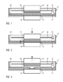
- the device has a trough 4, the trough bottom is transparent or translucent at least in a portion 6. This subregion 6 of the trough bottom covers at least the extension of an exposure unit 10, which is arranged under the trough bottom.
- the exposure unit 10 has a light source and a light modulator with which the intensity is controlled in a location-selective manner by a control unit in order to generate an exposure field with the geometry desired for the layer currently to be formed on the tub bottom 6.
- a laser may also be used in the exposure unit whose light beam successively scans the exposure field with the desired intensity pattern via a movable mirror which is controlled by a control unit.
- a building platform 12 is provided above the tub 4, which is supported by a lifting mechanism, not shown, so that it is held in a height-adjustable manner above the tub bottom 6 in the area above the exposure unit 10.
- the building platform 12 can also be transparent or translucent, so that light can be radiated through a further exposure unit above the build platform to at least in the formation of the first layer at the bottom of the build platform 12 to expose them from above, so that only at the Building platform hardened layer also adheres to this with high reliability.
- the procedure is as follows.
- the build platform 12 is lowered by the lifting mechanism in a controlled manner, so that (before the first exposure step) their underside dips into the filling of the photopolymerizable material 20 and the tub bottom 6 so far approaches that between the bottom of the build platform 12 and the tub bottom 6 exactly the desired layer thickness ⁇ (see Fig. 2 ) remains.
- photopolymerizable material is displaced from the gap between the bottom of the build platform 12 and the tub bottom 6.
- the location-selective exposure of the layer desired for this layer takes place in order to cure it in the desired shape.
- the first layer can also be an exposure from above through the transparent or translucent building platform 12, so that in particular in the contact area between the bottom of the build platform 12 and the photopolymerizable material, a secure and complete curing and thus a good adhesion of the first layer is ensured on the building platform 12.
- the construction platform is raised again by means of the lifting mechanism.
- the invention provides that an elongated mixing element 32 is occupied by the filling of photopolymerizable material 20 in the tub.
- the mixing element 32 on an elongated wire which is stretched between two on the side walls of the tub 4 movably mounted support arms 30.
- the support arms 30 may be movably mounted in guide slots 34 in the side walls of the tub 4, so that by moving the support arms 30 in the guide slots 34 of the tensioned between the support arms 30 wire 32 can be moved parallel to the tub bottom 6 relative to the tub 4.
- the elongate mixing element 32 has such dimensions and its movement is performed relative to the tub bottom in such a way that the upper edge of the elongated mixing element 32 remains below the material level of the filling of photopolymerizable material 20 in the tub outside the exposed area.
- the mixing element 32 in this case over the entire length of the wire below the material level in the tub, and it protrude only the support arms 30 on the material level in the tub.
- the arrangement of the elongate mixing element below the material level in the tub 4 has the consequence that the elongated mixing element 32 does not push material substantially before it in its movement relative to the tub through the exposed area, but rather over the mixing element 32 flows, making a slight upward movement thereto, as indicated by the arrow 21 in FIG Fig. 4 is indicated. It has been found that by this type of action on the photopolymerizable material in the tub, this is effectively stimulated to flow into the material-depleted exposed area between the build platform 12 and the exposure unit 10.
- the movement of the elongate mixing element 32 relative to the trough may be effected either by a linear drive at a fixed trough 4 which moves the support arms 30 along the guide slots 34 to provide the desired movement of the elongate mixing element 32 through the exposed area between the building platform 12 and Exposure unit 10 through.
- the elongated mixing element 32 may be held stationary in the space while the tub 4 is mounted horizontally movable and pushed by a drive back and forth, as in Fig. 6 is indicated, in which the trough 4 is shown in an end position of the movement with solid lines, while the opposite position of the trough is indicated by dashed lines.
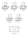
- the elongated mixing element 32 has a flat elongated plate which is inclined and has in its surface a plurality of openings through which photopolymerizable material can flow.
- the elongate plate is arranged so that its upper edge remains below the material level in the tub.
- mixing element 32 has a more horizontally disposed elongated plate 32 which carries at one end a wiper or Abziehlippe 33 of elastic material.
- the elongate mixing element 32 is moved with the elastic Abziehlippe 33 in contact with the trough bottom over this in order to pull along any attachments on the trough bottom.
- the elongated mixing element 32 has a kind of sash profile. This curved contour of the elongated mixing element 32 induces an increased vertical movement of the photopolymerizable material as it traverses, which results in a better flow of the material into the area to be filled.
- the elongate mixing element 32 has three horizontal metal wires lying one behind the other, while in the embodiment according to Fig. 11 three consecutive metal wires are moved at different heights on the bottom of the tub.
- the formation of the elongated mixing element with a plurality of wires lying one behind the other leads to an increased material movement, while the plurality of wires are moved through the material.
- Fig. 12 a schematic representation of a possible movement of the elongated mixing element 32 is shown.
- the elongated mixing element is moved transversely to its longitudinal direction through the trough, which is indicated by the long horizontal arrow.
- This movement transverse to the longitudinal direction is superimposed on an oscillating movement in the longitudinal direction of the elongated mixing element 32.
- This superposition of an additional movement component leads to a better inclusion in the tracking of material from all areas of the material filling the tub.
- the frequency of the oscillating movement in the longitudinal direction of the elongated mixing element 32 should be so high that several reciprocating movements take place in the longitudinal direction during movement of the elongated mixing element transversely to its longitudinal direction through the trough.
- the elongated mixing element 32 should be moved through the exposed area at least once through the trough. But it can also be provided that the elongated mixing element 32 is also moved back through the exposed area or that a multiple reciprocating motion is performed.
- the elongate mixing element is designed as a resistance heating element.
- a local heating of the photopolymerizable material in the region of the elongate mixing element is effected, whereby the viscosity of the material is reduced around the elongated mixing element and thereby facilitating a trailing and Nachffest the material in the area to be filled.
Landscapes
- Chemical & Material Sciences (AREA)
- Engineering & Computer Science (AREA)
- Materials Engineering (AREA)
- Physics & Mathematics (AREA)
- Manufacturing & Machinery (AREA)
- Mechanical Engineering (AREA)
- Optics & Photonics (AREA)
Priority Applications (4)
| Application Number | Priority Date | Filing Date | Title |
|---|---|---|---|
| EP20110160145 EP2505341B1 (fr) | 2011-03-29 | 2011-03-29 | Procédé de fabrication par couches d'un objet en matériau photopolymérisable hautement visqueux |
| ES11160145T ES2424738T3 (es) | 2011-03-29 | 2011-03-29 | Procedimiento para la formación en capas de un cuerpo moldeado de material foto polimerizable de alta viscosidad |
| JP2012067143A JP6174842B2 (ja) | 2011-03-29 | 2012-03-23 | 高粘性光重合可能材料で作られた成形体の層状構築のための方法 |
| US13/428,948 US9079357B2 (en) | 2011-03-29 | 2012-03-23 | Method for the layered construction of a shaped body made of highly viscous photopolymerizable material |
Applications Claiming Priority (1)
| Application Number | Priority Date | Filing Date | Title |
|---|---|---|---|
| EP20110160145 EP2505341B1 (fr) | 2011-03-29 | 2011-03-29 | Procédé de fabrication par couches d'un objet en matériau photopolymérisable hautement visqueux |
Publications (2)
| Publication Number | Publication Date |
|---|---|
| EP2505341A1 true EP2505341A1 (fr) | 2012-10-03 |
| EP2505341B1 EP2505341B1 (fr) | 2013-05-08 |
Family
ID=44558247
Family Applications (1)
| Application Number | Title | Priority Date | Filing Date |
|---|---|---|---|
| EP20110160145 Active EP2505341B1 (fr) | 2011-03-29 | 2011-03-29 | Procédé de fabrication par couches d'un objet en matériau photopolymérisable hautement visqueux |
Country Status (4)
| Country | Link |
|---|---|
| US (1) | US9079357B2 (fr) |
| EP (1) | EP2505341B1 (fr) |
| JP (1) | JP6174842B2 (fr) |
| ES (1) | ES2424738T3 (fr) |
Cited By (14)
| Publication number | Priority date | Publication date | Assignee | Title |
|---|---|---|---|---|
| EP2875934A1 (fr) | 2013-11-22 | 2015-05-27 | Technische Universität Wien | Dispositif de traitement de matériau photopolymérisable pour le montage en couche d'un corps moulé |
| WO2015074088A2 (fr) | 2013-11-22 | 2015-05-28 | Technische Universität Wien | Dispositif de transformation de matériau photopolymérisable destiné à la fabrication couche par couche d'un élément façonné |
| DE102014004634A1 (de) * | 2014-04-01 | 2015-10-01 | Cl Schutzrechtsverwaltungs Gmbh | Vorrichtung zur generativen Herstellung dreidimensionaler Objekte |
| EP3159148A1 (fr) * | 2011-04-20 | 2017-04-26 | Dws S.R.L. | Procédé de fabrication d'un objet tridimensionnel |
| WO2017161398A1 (fr) * | 2016-03-25 | 2017-09-28 | Klaus Stadlmann | Dispositif et procédé pour générer un corps en trois dimensions |
| EP3284583A1 (fr) | 2016-08-18 | 2018-02-21 | Cubicure GmbH | Procede et dispositif de fabrication generative par lithographie de corps de formage tridimensionnels |
| EP3290188A1 (fr) | 2016-08-30 | 2018-03-07 | Lithoz GmbH | Procédé de consolidation d'un matériau réfléchissant de manière diffuse et photopolyméralisable. |
| US10821668B2 (en) | 2018-01-26 | 2020-11-03 | General Electric Company | Method for producing a component layer-by- layer |
| US10821669B2 (en) | 2018-01-26 | 2020-11-03 | General Electric Company | Method for producing a component layer-by-layer |
| US10864675B2 (en) | 2015-04-02 | 2020-12-15 | Lithoz Gmbh | Method for the layered construction of a shaped body |
| US10967564B2 (en) | 2015-04-02 | 2021-04-06 | Lithoz Gmbh | Method for the layered construction of a shaped body |
| DE102020002430A1 (de) | 2020-04-22 | 2021-10-28 | Ivoclar Vivadent Ag | Bauplattform, vorrichtung und verfahren zum schichtweisen oder kontinuierlichen aufbauen eines werkstücks |
| EP4008523A1 (fr) | 2020-12-03 | 2022-06-08 | Lithoz GmbH | Procédé et dispositif de construction en couches d'un composant en matière photopolymerisable |
| US12172379B2 (en) | 2021-08-11 | 2024-12-24 | General Electric Company | Cleaning system for additive manufacturing |
Families Citing this family (58)
| Publication number | Priority date | Publication date | Assignee | Title |
|---|---|---|---|---|
| ITVI20120172A1 (it) * | 2012-07-16 | 2014-01-17 | Dws Srl | Metodo stereolitografico per la produzione di un oggetto tridimensionale, comprendente un movimento di avvicinamento intermittente di una superficie di supporto per detto oggetto al fondo di un recipiente, e macchina stereolitografica impiegante tale |
| WO2015051095A1 (fr) | 2013-10-04 | 2015-04-09 | 3M Innovative Properties Company | Ébauche de fraisage dentaire |
| US9527244B2 (en) * | 2014-02-10 | 2016-12-27 | Global Filtration Systems | Apparatus and method for forming three-dimensional objects from solidifiable paste |
| KR101619696B1 (ko) * | 2015-03-16 | 2016-05-10 | 엘지전자 주식회사 | 3d 프린터 |
| US20170028647A1 (en) * | 2015-07-29 | 2017-02-02 | Industrial Technology Research Institute | Three dimensional printing system |
| EP3362265B1 (fr) | 2015-10-15 | 2021-04-21 | Saint-Gobain Ceramics&Plastics, Inc. | Procédé de formation d'un corps tridimensionnel à partir d'un mélange à haute teneur en particules solides |
| AT518051B1 (de) * | 2016-04-19 | 2017-07-15 | Klaus Stadlmann Dr | Vorrichtung und Verfahren zur Steigerung der Anhaftung einer Bauteilschicht an einem Trägerobjekt |
| US10434759B2 (en) | 2016-08-12 | 2019-10-08 | General Electric Company | Methods for fine feature detail for additive manufacturing |
| US10343388B2 (en) | 2016-09-16 | 2019-07-09 | General Electric Company | Methods and apparatus for thin-walled geometries for additive manufacturing |
| CN106426914A (zh) * | 2016-10-11 | 2017-02-22 | 张雅文 | 一种铺底挂扫式高速sla激光3d打印机 |
| US20180161854A1 (en) | 2016-12-13 | 2018-06-14 | General Electric Company | Integrated casting core-shell structure |
| US20180161852A1 (en) | 2016-12-13 | 2018-06-14 | General Electric Company | Integrated casting core-shell structure with printed tubes for making cast component |
| US20180161856A1 (en) * | 2016-12-13 | 2018-06-14 | General Electric Company | Integrated casting core-shell structure and filter for making cast component |
| US20180161857A1 (en) * | 2016-12-13 | 2018-06-14 | General Electric Company | Integrated casting core-shell structure for making cast components having thin root components |
| US20180161853A1 (en) | 2016-12-13 | 2018-06-14 | General Electric Company | Integrated casting core-shell structure with floating tip plenum |
| US10807154B2 (en) | 2016-12-13 | 2020-10-20 | General Electric Company | Integrated casting core-shell structure for making cast component with cooling holes in inaccessible locations |
| US11813669B2 (en) | 2016-12-13 | 2023-11-14 | General Electric Company | Method for making an integrated core-shell structure |
| US20180161855A1 (en) * | 2016-12-13 | 2018-06-14 | General Electric Company | Multi-piece integrated core-shell structure with standoff and/or bumper for making cast component |
| US20180161859A1 (en) | 2016-12-13 | 2018-06-14 | General Electric Company | Integrated casting core-shell structure for making cast component with non-linear holes |
| US20180161866A1 (en) | 2016-12-13 | 2018-06-14 | General Electric Company | Multi-piece integrated core-shell structure for making cast component |
| US11173542B2 (en) | 2017-06-28 | 2021-11-16 | General Electric Company | Additively manufactured casting core-shell mold and ceramic shell with variable thermal properties |
| US10974312B2 (en) | 2017-06-28 | 2021-04-13 | General Electric Company | Additively manufactured casting core-shell mold with integrated filter and ceramic shell |
| US10391670B2 (en) | 2017-06-28 | 2019-08-27 | General Electric Company | Additively manufactured integrated casting core structure with ceramic shell |
| US10391549B2 (en) * | 2017-06-28 | 2019-08-27 | General Electric Company | Additively manufactured casting core-shell hybrid mold and ceramic shell |
| US11192172B2 (en) * | 2017-06-28 | 2021-12-07 | General Electric Company | Additively manufactured interlocking casting core structure with ceramic shell |
| CN110869421A (zh) | 2017-07-21 | 2020-03-06 | 美国圣戈班性能塑料公司 | 形成三维本体的方法 |
| US11066335B2 (en) | 2017-09-06 | 2021-07-20 | General Electric Company | Articles for creating hollow structures in ceramic matrix composites |
| WO2019118946A2 (fr) * | 2017-12-15 | 2019-06-20 | Chartrain Nicholas | Appareil de stéréolithographie haute-température et procédés d'utilisation de celui-ci |
| CN108215154B (zh) * | 2017-12-29 | 2020-01-14 | 南京三迭纪医药科技有限公司 | 一种3d打印设备的平台装置 |
| US11130170B2 (en) * | 2018-02-02 | 2021-09-28 | General Electric Company | Integrated casting core-shell structure for making cast component with novel cooling hole architecture |
| CN110181813A (zh) * | 2018-02-23 | 2019-08-30 | 三纬国际立体列印科技股份有限公司 | 立体打印装置 |
| CN110435134A (zh) * | 2018-05-02 | 2019-11-12 | 三纬国际立体列印科技股份有限公司 | 立体打印装置 |
| US11373802B2 (en) | 2018-07-10 | 2022-06-28 | GM Global Technology Operations LLC | Magnet manufacturing by additive manufacturing using slurry |
| EP3938176B1 (fr) * | 2019-03-15 | 2024-03-06 | Formlabs, Inc. | Systèmes de mélange pour la fabrication additive |
| US11707883B2 (en) | 2020-11-20 | 2023-07-25 | General Electric Company | Foil interaction device for additive manufacturing |
| US11865780B2 (en) | 2021-02-26 | 2024-01-09 | General Electric Company | Accumalator assembly for additive manufacturing |
| US12589549B2 (en) | 2021-04-27 | 2026-03-31 | General Electric Company | Systems and methods for additive manufacturing |
| US11951679B2 (en) | 2021-06-16 | 2024-04-09 | General Electric Company | Additive manufacturing system |
| US11731367B2 (en) | 2021-06-23 | 2023-08-22 | General Electric Company | Drive system for additive manufacturing |
| US11958249B2 (en) | 2021-06-24 | 2024-04-16 | General Electric Company | Reclamation system for additive manufacturing |
| US11958250B2 (en) | 2021-06-24 | 2024-04-16 | General Electric Company | Reclamation system for additive manufacturing |
| US11826950B2 (en) | 2021-07-09 | 2023-11-28 | General Electric Company | Resin management system for additive manufacturing |
| US12370741B2 (en) | 2021-08-13 | 2025-07-29 | General Electric Company | Material deposition assembly for additive manufacturing |
| US12296535B2 (en) | 2021-08-24 | 2025-05-13 | General Electric Company | Attachment structure for additive manufacturing |
| US11813799B2 (en) | 2021-09-01 | 2023-11-14 | General Electric Company | Control systems and methods for additive manufacturing |
| US12053925B2 (en) | 2021-10-14 | 2024-08-06 | Align Technology, Inc. | Recoating system including multiple blades |
| WO2023064488A1 (fr) * | 2021-10-14 | 2023-04-20 | Align Technology, Inc. | Système de nouveau revêtement |
| EP4249216A1 (fr) | 2022-03-23 | 2023-09-27 | General Electric Company | Systèmes et procédés de fabrication additive |
| US12403654B2 (en) | 2022-09-30 | 2025-09-02 | General Electric Company | Systems and methods for additive manufacturing |
| US12392290B2 (en) | 2022-11-01 | 2025-08-19 | General Electric Company | Gas turbine engine |
| US12196131B2 (en) | 2022-11-01 | 2025-01-14 | General Electric Company | Gas turbine engine |
| US12428992B2 (en) | 2022-11-01 | 2025-09-30 | General Electric Company | Gas turbine engine |
| US12503980B2 (en) | 2022-11-01 | 2025-12-23 | General Electric Company | Gas turbine engine |
| US12410753B2 (en) | 2022-11-01 | 2025-09-09 | General Electric Company | Gas turbine engine |
| US12535033B2 (en) | 2022-11-01 | 2026-01-27 | General Electric Company | Gas turbine engine |
| US12618378B2 (en) | 2022-11-01 | 2026-05-05 | General Electric Company | Gas turbine engine |
| US12618332B2 (en) | 2022-11-01 | 2026-05-05 | General Electric Company | Gas turbine engine |
| US12540551B1 (en) | 2025-07-01 | 2026-02-03 | General Electric Company | Gas turbine engines including splittered airfoils |
Citations (4)
| Publication number | Priority date | Publication date | Assignee | Title |
|---|---|---|---|---|
| EP0484086A1 (fr) * | 1990-10-29 | 1992-05-06 | E.I. Du Pont De Nemours And Company | Reproduction solide avec film demi-transparent |
| EP0597114A1 (fr) * | 1992-05-28 | 1994-05-18 | CMET, Inc. | Appareil de moulage a photodurcissement avec procede de reenduction et methode de moulage a thermodurcissement ameliores |
| WO1998006560A1 (fr) | 1996-08-08 | 1998-02-19 | Sri International | Appareil de fabrication automatique d'objets tridimensionnels, et procedes d'utilisation associes |
| WO2010045950A1 (fr) | 2008-10-20 | 2010-04-29 | Ivoclar Vivadent Ag | Dispositif et procédé de traitement d’un matériau photopolymérisable permettant la réalisation par couches de corps moulés |
Family Cites Families (7)
| Publication number | Priority date | Publication date | Assignee | Title |
|---|---|---|---|---|
| US3980017A (en) * | 1974-10-31 | 1976-09-14 | Black James | Stencil screen coating apparatus |
| US5174931A (en) * | 1988-09-26 | 1992-12-29 | 3D Systems, Inc. | Method of and apparatus for making a three-dimensional product by stereolithography |
| US5474719A (en) * | 1991-02-14 | 1995-12-12 | E. I. Du Pont De Nemours And Company | Method for forming solid objects utilizing viscosity reducible compositions |
| US6051179A (en) * | 1997-03-19 | 2000-04-18 | Replicator Systems, Inc. | Apparatus and method for production of three-dimensional models by spatial light modulator |
| US6153142A (en) * | 1999-02-08 | 2000-11-28 | 3D Systems, Inc. | Stereolithographic method and apparatus for production of three dimensional objects with enhanced thermal control of the build environment |
| JP5571090B2 (ja) * | 2008-10-20 | 2014-08-13 | テクニッシュ ユニべルシタット ウィーン | 層内で物体を構築するために光重合性材料を処理するためのデバイスおよび方法 |
| EP2251185A1 (fr) * | 2009-05-11 | 2010-11-17 | Ivoclar Vivadent AG | Procédé et dispositif de fabrication générative d'un corps de formage doté de couches non planaires |
-
2011
- 2011-03-29 EP EP20110160145 patent/EP2505341B1/fr active Active
- 2011-03-29 ES ES11160145T patent/ES2424738T3/es active Active
-
2012
- 2012-03-23 JP JP2012067143A patent/JP6174842B2/ja active Active
- 2012-03-23 US US13/428,948 patent/US9079357B2/en active Active
Patent Citations (4)
| Publication number | Priority date | Publication date | Assignee | Title |
|---|---|---|---|---|
| EP0484086A1 (fr) * | 1990-10-29 | 1992-05-06 | E.I. Du Pont De Nemours And Company | Reproduction solide avec film demi-transparent |
| EP0597114A1 (fr) * | 1992-05-28 | 1994-05-18 | CMET, Inc. | Appareil de moulage a photodurcissement avec procede de reenduction et methode de moulage a thermodurcissement ameliores |
| WO1998006560A1 (fr) | 1996-08-08 | 1998-02-19 | Sri International | Appareil de fabrication automatique d'objets tridimensionnels, et procedes d'utilisation associes |
| WO2010045950A1 (fr) | 2008-10-20 | 2010-04-29 | Ivoclar Vivadent Ag | Dispositif et procédé de traitement d’un matériau photopolymérisable permettant la réalisation par couches de corps moulés |
Cited By (27)
| Publication number | Priority date | Publication date | Assignee | Title |
|---|---|---|---|---|
| EP3159148A1 (fr) * | 2011-04-20 | 2017-04-26 | Dws S.R.L. | Procédé de fabrication d'un objet tridimensionnel |
| WO2015075094A1 (fr) * | 2013-11-22 | 2015-05-28 | Technische Universität Wien | Dispositif de traitement de matière photopolymérisable pour former un corps moulé par couches |
| WO2015074088A2 (fr) | 2013-11-22 | 2015-05-28 | Technische Universität Wien | Dispositif de transformation de matériau photopolymérisable destiné à la fabrication couche par couche d'un élément façonné |
| WO2015074088A3 (fr) * | 2013-11-22 | 2015-07-16 | Technische Universität Wien | Dispositif de transformation de matériau photopolymérisable destiné à la fabrication couche par couche d'un élément façonné |
| EP2875934A1 (fr) | 2013-11-22 | 2015-05-27 | Technische Universität Wien | Dispositif de traitement de matériau photopolymérisable pour le montage en couche d'un corps moulé |
| DE102014004634A1 (de) * | 2014-04-01 | 2015-10-01 | Cl Schutzrechtsverwaltungs Gmbh | Vorrichtung zur generativen Herstellung dreidimensionaler Objekte |
| US10864675B2 (en) | 2015-04-02 | 2020-12-15 | Lithoz Gmbh | Method for the layered construction of a shaped body |
| US10967564B2 (en) | 2015-04-02 | 2021-04-06 | Lithoz Gmbh | Method for the layered construction of a shaped body |
| RU2759969C2 (ru) * | 2016-03-25 | 2021-11-19 | Клаус ШТАДЛЬМАНН | Система и способ для формирования трехмерного тела |
| WO2017161398A1 (fr) * | 2016-03-25 | 2017-09-28 | Klaus Stadlmann | Dispositif et procédé pour générer un corps en trois dimensions |
| US11179882B2 (en) | 2016-03-25 | 2021-11-23 | Klaus Stadlmann | System and method for generating a three-dimensional body |
| AT518465A1 (de) * | 2016-03-25 | 2017-10-15 | Stadlmann Klaus | Anlage und Verfahren zum Generieren eines dreidimensionalen Körpers |
| AT518465B1 (de) * | 2016-03-25 | 2017-11-15 | Stadlmann Klaus | Anlage und Verfahren zum Generieren eines dreidimensionalen Körpers |
| EP3284583A1 (fr) | 2016-08-18 | 2018-02-21 | Cubicure GmbH | Procede et dispositif de fabrication generative par lithographie de corps de formage tridimensionnels |
| US11642837B2 (en) | 2016-08-18 | 2023-05-09 | Cubicure Gmbh | Method and device for lithography-based additive production of three-dimensional shaped bodies |
| WO2018032022A1 (fr) | 2016-08-18 | 2018-02-22 | Cubicure Gmhh | Procédé et dispositif de fabrication additive de corps moulés tridimensionnels basée sur la lithographie |
| US12330368B2 (en) | 2016-08-18 | 2025-06-17 | Cubicure Gmbh | Method and device for lithography-based additive production of three-dimensional shaped bodies |
| US11951681B2 (en) | 2016-08-18 | 2024-04-09 | Cubicure Gmbh | Method and device for lithography-based additive production of three-dimensional shaped bodies |
| WO2018039688A1 (fr) | 2016-08-30 | 2018-03-08 | Lithoz Gmbh | Procédé de durcissement d'un matériau photopolymérisable à réflexion diffuse |
| EP3290188A1 (fr) | 2016-08-30 | 2018-03-07 | Lithoz GmbH | Procédé de consolidation d'un matériau réfléchissant de manière diffuse et photopolyméralisable. |
| US10821668B2 (en) | 2018-01-26 | 2020-11-03 | General Electric Company | Method for producing a component layer-by- layer |
| US10821669B2 (en) | 2018-01-26 | 2020-11-03 | General Electric Company | Method for producing a component layer-by-layer |
| US11623398B2 (en) | 2018-01-26 | 2023-04-11 | General Electric Company | Multi-level vat for additive manufacturing |
| DE102020002430A1 (de) | 2020-04-22 | 2021-10-28 | Ivoclar Vivadent Ag | Bauplattform, vorrichtung und verfahren zum schichtweisen oder kontinuierlichen aufbauen eines werkstücks |
| DE102020002430B4 (de) | 2020-04-22 | 2021-12-16 | Ivoclar Vivadent Ag | Bauplattform, vorrichtung und verfahren zum schichtweisen oder kontinuierlichen aufbauen eines werkstücks |
| EP4008523A1 (fr) | 2020-12-03 | 2022-06-08 | Lithoz GmbH | Procédé et dispositif de construction en couches d'un composant en matière photopolymerisable |
| US12172379B2 (en) | 2021-08-11 | 2024-12-24 | General Electric Company | Cleaning system for additive manufacturing |
Also Published As
| Publication number | Publication date |
|---|---|
| ES2424738T3 (es) | 2013-10-08 |
| US20120248657A1 (en) | 2012-10-04 |
| US9079357B2 (en) | 2015-07-14 |
| JP2012206513A (ja) | 2012-10-25 |
| JP6174842B2 (ja) | 2017-08-02 |
| EP2505341B1 (fr) | 2013-05-08 |
Similar Documents
| Publication | Publication Date | Title |
|---|---|---|
| EP2505341B1 (fr) | Procédé de fabrication par couches d'un objet en matériau photopolymérisable hautement visqueux | |
| EP3071394B1 (fr) | Dispositif de transformation de matériau photopolymérisable destiné à la fabrication couche par couche d'un élément façonné | |
| EP2875934B1 (fr) | Dispositif de traitement de matériau photopolymérisable pour le montage en couche d'un corps moulé | |
| DE4400523C2 (de) | Verfahren und Vorrichtung zum Herstellen eines dreidimensionalen Objekts | |
| EP3705266B1 (fr) | Procédé de fabrication additive d'un produit tridimensionnel | |
| EP0738584B1 (fr) | Dispositif et procédé pour la fabrication d'un objet tridimensionnel | |
| EP2864108B1 (fr) | Dispositif et procédé de fabrication par couches d'un objet tridimensionnel | |
| DE4134265C2 (de) | Vorrichtung und Verfahren zur Herstellung eines dreidimensionalen Objekts mittels Stereographie | |
| DE19507881B4 (de) | Verfahren zum Stützen eines Objekts, verfertigt durch Stereolithographie oder ein anderes schnelles Prototypen-Fertigungsverfahren | |
| DE69420283T2 (de) | Verfahren und vorrichtung zur herstellung von werkstücken durch phototransformation von stoff | |
| EP3277481B1 (fr) | Procédé et dispositif de fabrication additive d'un corps | |
| EP3277482B1 (fr) | Procédé et dispositif de fabrication additive d'un corps | |
| DE102008022946A1 (de) | Vorrichtung und Verfahren zum Aufbringen von Pulvern oder Pasten | |
| WO2001072501A1 (fr) | Procede et dispositif de production de composants realises dans des materiaux durcissables a la lumiere | |
| DE102007040755A1 (de) | Lasersintervorrichtung sowie Verfahren zum Herstellen von dreidimensionalen Objekten durch selektives Lasersintern | |
| WO2019063094A1 (fr) | Pièces façonnées imprimées en 3d à partir de plus d'un matériau silicone | |
| DE69704623T2 (de) | Verfahren und vorrichtung zur herstellung eines dreidimensionalen gegenstandes aus einer härtbaren flüssigkeit | |
| DE102015121437A1 (de) | Vorrichtung und Verfahren zur Herstellung eines dreidimensionalen metallischen Formkörpers | |
| EP3668704B1 (fr) | Ensemble et procédé pour produire une structure 3d | |
| DE4414775A1 (de) | Vorrichtung und Verfahren zum Herstellen eines dreidimensionalen Objekts | |
| DE9400364U1 (de) | Vorrichtung zum Herstellen eines dreidimensionalen Objekts | |
| DE102019007480A1 (de) | Anordnung und Verfahren zum Erzeugen einer Schicht eines partikelförmigen Baumaterials in einem 3D-Drucker | |
| DE4110903C2 (fr) | ||
| DE102020105524A1 (de) | Additive Herstellungseinrichtung und Verfahren zur additiven Herstellung eines dreidimensionalen Erzeugnisses | |
| DE102019114402B4 (de) | Verfahren zum Herstellen eines Beton-Fertigbauteils |
Legal Events
| Date | Code | Title | Description |
|---|---|---|---|
| PUAI | Public reference made under article 153(3) epc to a published international application that has entered the european phase |
Free format text: ORIGINAL CODE: 0009012 |
|
| AK | Designated contracting states |
Kind code of ref document: A1 Designated state(s): AL AT BE BG CH CY CZ DE DK EE ES FI FR GB GR HR HU IE IS IT LI LT LU LV MC MK MT NL NO PL PT RO RS SE SI SK SM TR |
|
| AX | Request for extension of the european patent |
Extension state: BA ME |
|
| 17P | Request for examination filed |
Effective date: 20120917 |
|
| GRAP | Despatch of communication of intention to grant a patent |
Free format text: ORIGINAL CODE: EPIDOSNIGR1 |
|
| GRAS | Grant fee paid |
Free format text: ORIGINAL CODE: EPIDOSNIGR3 |
|
| GRAA | (expected) grant |
Free format text: ORIGINAL CODE: 0009210 |
|
| AK | Designated contracting states |
Kind code of ref document: B1 Designated state(s): AL AT BE BG CH CY CZ DE DK EE ES FI FR GB GR HR HU IE IS IT LI LT LU LV MC MK MT NL NO PL PT RO RS SE SI SK SM TR |
|
| REG | Reference to a national code |
Ref country code: GB Ref legal event code: FG4D Free format text: NOT ENGLISH |
|
| REG | Reference to a national code |
Ref country code: CH Ref legal event code: NV Representative=s name: KELLER AND PARTNER PATENTANWAELTE AG, CH Ref country code: CH Ref legal event code: EP Ref country code: AT Ref legal event code: REF Ref document number: 610860 Country of ref document: AT Kind code of ref document: T Effective date: 20130515 |
|
| REG | Reference to a national code |
Ref country code: IE Ref legal event code: FG4D Free format text: LANGUAGE OF EP DOCUMENT: GERMAN |
|
| REG | Reference to a national code |
Ref country code: DE Ref legal event code: R096 Ref document number: 502011000718 Country of ref document: DE Effective date: 20130704 |
|
| REG | Reference to a national code |
Ref country code: SE Ref legal event code: TRGR |
|
| REG | Reference to a national code |
Ref country code: NL Ref legal event code: T3 |
|
| REG | Reference to a national code |
Ref country code: ES Ref legal event code: FG2A Ref document number: 2424738 Country of ref document: ES Kind code of ref document: T3 Effective date: 20131008 |
|
| REG | Reference to a national code |
Ref country code: LT Ref legal event code: MG4D |
|
| PG25 | Lapsed in a contracting state [announced via postgrant information from national office to epo] |
Ref country code: GR Free format text: LAPSE BECAUSE OF FAILURE TO SUBMIT A TRANSLATION OF THE DESCRIPTION OR TO PAY THE FEE WITHIN THE PRESCRIBED TIME-LIMIT Effective date: 20130809 Ref country code: FI Free format text: LAPSE BECAUSE OF FAILURE TO SUBMIT A TRANSLATION OF THE DESCRIPTION OR TO PAY THE FEE WITHIN THE PRESCRIBED TIME-LIMIT Effective date: 20130508 Ref country code: NO Free format text: LAPSE BECAUSE OF FAILURE TO SUBMIT A TRANSLATION OF THE DESCRIPTION OR TO PAY THE FEE WITHIN THE PRESCRIBED TIME-LIMIT Effective date: 20130808 Ref country code: SI Free format text: LAPSE BECAUSE OF FAILURE TO SUBMIT A TRANSLATION OF THE DESCRIPTION OR TO PAY THE FEE WITHIN THE PRESCRIBED TIME-LIMIT Effective date: 20130508 Ref country code: PT Free format text: LAPSE BECAUSE OF FAILURE TO SUBMIT A TRANSLATION OF THE DESCRIPTION OR TO PAY THE FEE WITHIN THE PRESCRIBED TIME-LIMIT Effective date: 20130909 Ref country code: LT Free format text: LAPSE BECAUSE OF FAILURE TO SUBMIT A TRANSLATION OF THE DESCRIPTION OR TO PAY THE FEE WITHIN THE PRESCRIBED TIME-LIMIT Effective date: 20130508 Ref country code: IS Free format text: LAPSE BECAUSE OF FAILURE TO SUBMIT A TRANSLATION OF THE DESCRIPTION OR TO PAY THE FEE WITHIN THE PRESCRIBED TIME-LIMIT Effective date: 20130908 |
|
| PG25 | Lapsed in a contracting state [announced via postgrant information from national office to epo] |
Ref country code: RS Free format text: LAPSE BECAUSE OF FAILURE TO SUBMIT A TRANSLATION OF THE DESCRIPTION OR TO PAY THE FEE WITHIN THE PRESCRIBED TIME-LIMIT Effective date: 20130508 Ref country code: PL Free format text: LAPSE BECAUSE OF FAILURE TO SUBMIT A TRANSLATION OF THE DESCRIPTION OR TO PAY THE FEE WITHIN THE PRESCRIBED TIME-LIMIT Effective date: 20130508 Ref country code: HR Free format text: LAPSE BECAUSE OF FAILURE TO SUBMIT A TRANSLATION OF THE DESCRIPTION OR TO PAY THE FEE WITHIN THE PRESCRIBED TIME-LIMIT Effective date: 20130508 Ref country code: CY Free format text: LAPSE BECAUSE OF FAILURE TO SUBMIT A TRANSLATION OF THE DESCRIPTION OR TO PAY THE FEE WITHIN THE PRESCRIBED TIME-LIMIT Effective date: 20130508 Ref country code: BG Free format text: LAPSE BECAUSE OF FAILURE TO SUBMIT A TRANSLATION OF THE DESCRIPTION OR TO PAY THE FEE WITHIN THE PRESCRIBED TIME-LIMIT Effective date: 20130808 |
|
| PG25 | Lapsed in a contracting state [announced via postgrant information from national office to epo] |
Ref country code: LV Free format text: LAPSE BECAUSE OF FAILURE TO SUBMIT A TRANSLATION OF THE DESCRIPTION OR TO PAY THE FEE WITHIN THE PRESCRIBED TIME-LIMIT Effective date: 20130508 |
|
| PG25 | Lapsed in a contracting state [announced via postgrant information from national office to epo] |
Ref country code: CZ Free format text: LAPSE BECAUSE OF FAILURE TO SUBMIT A TRANSLATION OF THE DESCRIPTION OR TO PAY THE FEE WITHIN THE PRESCRIBED TIME-LIMIT Effective date: 20130508 Ref country code: DK Free format text: LAPSE BECAUSE OF FAILURE TO SUBMIT A TRANSLATION OF THE DESCRIPTION OR TO PAY THE FEE WITHIN THE PRESCRIBED TIME-LIMIT Effective date: 20130508 Ref country code: SK Free format text: LAPSE BECAUSE OF FAILURE TO SUBMIT A TRANSLATION OF THE DESCRIPTION OR TO PAY THE FEE WITHIN THE PRESCRIBED TIME-LIMIT Effective date: 20130508 Ref country code: EE Free format text: LAPSE BECAUSE OF FAILURE TO SUBMIT A TRANSLATION OF THE DESCRIPTION OR TO PAY THE FEE WITHIN THE PRESCRIBED TIME-LIMIT Effective date: 20130508 |
|
| PG25 | Lapsed in a contracting state [announced via postgrant information from national office to epo] |
Ref country code: RO Free format text: LAPSE BECAUSE OF FAILURE TO SUBMIT A TRANSLATION OF THE DESCRIPTION OR TO PAY THE FEE WITHIN THE PRESCRIBED TIME-LIMIT Effective date: 20130508 |
|
| PLBE | No opposition filed within time limit |
Free format text: ORIGINAL CODE: 0009261 |
|
| STAA | Information on the status of an ep patent application or granted ep patent |
Free format text: STATUS: NO OPPOSITION FILED WITHIN TIME LIMIT |
|
| 26N | No opposition filed |
Effective date: 20140211 |
|
| REG | Reference to a national code |
Ref country code: DE Ref legal event code: R097 Ref document number: 502011000718 Country of ref document: DE Effective date: 20140211 |
|
| PG25 | Lapsed in a contracting state [announced via postgrant information from national office to epo] |
Ref country code: LU Free format text: LAPSE BECAUSE OF FAILURE TO SUBMIT A TRANSLATION OF THE DESCRIPTION OR TO PAY THE FEE WITHIN THE PRESCRIBED TIME-LIMIT Effective date: 20140329 |
|
| REG | Reference to a national code |
Ref country code: IE Ref legal event code: MM4A |
|
| PG25 | Lapsed in a contracting state [announced via postgrant information from national office to epo] |
Ref country code: IE Free format text: LAPSE BECAUSE OF NON-PAYMENT OF DUE FEES Effective date: 20140329 |
|
| REG | Reference to a national code |
Ref country code: CH Ref legal event code: PCAR Free format text: NEW ADDRESS: EIGERSTRASSE 2 POSTFACH, 3000 BERN 14 (CH) |
|
| PG25 | Lapsed in a contracting state [announced via postgrant information from national office to epo] |
Ref country code: MT Free format text: LAPSE BECAUSE OF FAILURE TO SUBMIT A TRANSLATION OF THE DESCRIPTION OR TO PAY THE FEE WITHIN THE PRESCRIBED TIME-LIMIT Effective date: 20130508 |
|
| REG | Reference to a national code |
Ref country code: FR Ref legal event code: PLFP Year of fee payment: 6 |
|
| PG25 | Lapsed in a contracting state [announced via postgrant information from national office to epo] |
Ref country code: SM Free format text: LAPSE BECAUSE OF FAILURE TO SUBMIT A TRANSLATION OF THE DESCRIPTION OR TO PAY THE FEE WITHIN THE PRESCRIBED TIME-LIMIT Effective date: 20130508 |
|
| PG25 | Lapsed in a contracting state [announced via postgrant information from national office to epo] |
Ref country code: MC Free format text: LAPSE BECAUSE OF FAILURE TO SUBMIT A TRANSLATION OF THE DESCRIPTION OR TO PAY THE FEE WITHIN THE PRESCRIBED TIME-LIMIT Effective date: 20130508 |
|
| PG25 | Lapsed in a contracting state [announced via postgrant information from national office to epo] |
Ref country code: HU Free format text: LAPSE BECAUSE OF FAILURE TO SUBMIT A TRANSLATION OF THE DESCRIPTION OR TO PAY THE FEE WITHIN THE PRESCRIBED TIME-LIMIT; INVALID AB INITIO Effective date: 20110329 Ref country code: TR Free format text: LAPSE BECAUSE OF FAILURE TO SUBMIT A TRANSLATION OF THE DESCRIPTION OR TO PAY THE FEE WITHIN THE PRESCRIBED TIME-LIMIT Effective date: 20130508 |
|
| REG | Reference to a national code |
Ref country code: DE Ref legal event code: R079 Ref document number: 502011000718 Country of ref document: DE Free format text: PREVIOUS MAIN CLASS: B29C0067000000 Ipc: B29C0064106000 |
|
| REG | Reference to a national code |
Ref country code: FR Ref legal event code: PLFP Year of fee payment: 7 |
|
| PG25 | Lapsed in a contracting state [announced via postgrant information from national office to epo] |
Ref country code: BE Free format text: LAPSE BECAUSE OF NON-PAYMENT OF DUE FEES Effective date: 20140331 |
|
| REG | Reference to a national code |
Ref country code: FR Ref legal event code: PLFP Year of fee payment: 8 |
|
| PG25 | Lapsed in a contracting state [announced via postgrant information from national office to epo] |
Ref country code: MK Free format text: LAPSE BECAUSE OF FAILURE TO SUBMIT A TRANSLATION OF THE DESCRIPTION OR TO PAY THE FEE WITHIN THE PRESCRIBED TIME-LIMIT Effective date: 20130508 |
|
| PG25 | Lapsed in a contracting state [announced via postgrant information from national office to epo] |
Ref country code: AL Free format text: LAPSE BECAUSE OF FAILURE TO SUBMIT A TRANSLATION OF THE DESCRIPTION OR TO PAY THE FEE WITHIN THE PRESCRIBED TIME-LIMIT Effective date: 20130508 |
|
| REG | Reference to a national code |
Ref country code: CH Ref legal event code: PFA Owner name: IVOCLAR VIVADENT AG, AT Free format text: FORMER OWNER: IVOCLAR VIVADENT AG, AT |
|
| P01 | Opt-out of the competence of the unified patent court (upc) registered |
Effective date: 20230607 |
|
| PGFP | Annual fee paid to national office [announced via postgrant information from national office to epo] |
Ref country code: IT Payment date: 20250306 Year of fee payment: 15 |
|
| PGFP | Annual fee paid to national office [announced via postgrant information from national office to epo] |
Ref country code: ES Payment date: 20250403 Year of fee payment: 15 |
|
| PGFP | Annual fee paid to national office [announced via postgrant information from national office to epo] |
Ref country code: CH Payment date: 20250429 Year of fee payment: 15 |
|
| PGFP | Annual fee paid to national office [announced via postgrant information from national office to epo] |
Ref country code: SE Payment date: 20260323 Year of fee payment: 16 |
|
| PGFP | Annual fee paid to national office [announced via postgrant information from national office to epo] |
Ref country code: GB Payment date: 20260324 Year of fee payment: 16 |
|
| PGFP | Annual fee paid to national office [announced via postgrant information from national office to epo] |
Ref country code: DE Payment date: 20260320 Year of fee payment: 16 |
|
| PGFP | Annual fee paid to national office [announced via postgrant information from national office to epo] |
Ref country code: AT Payment date: 20260320 Year of fee payment: 16 |
|
| PGFP | Annual fee paid to national office [announced via postgrant information from national office to epo] |
Ref country code: NL Payment date: 20260320 Year of fee payment: 16 |
|
| PGFP | Annual fee paid to national office [announced via postgrant information from national office to epo] |
Ref country code: FR Payment date: 20260327 Year of fee payment: 16 |