EP4008523A1 - Procédé et dispositif de construction en couches d'un composant en matière photopolymerisable - Google Patents
Procédé et dispositif de construction en couches d'un composant en matière photopolymerisable Download PDFInfo
- Publication number
- EP4008523A1 EP4008523A1 EP20020586.2A EP20020586A EP4008523A1 EP 4008523 A1 EP4008523 A1 EP 4008523A1 EP 20020586 A EP20020586 A EP 20020586A EP 4008523 A1 EP4008523 A1 EP 4008523A1
- Authority
- EP
- European Patent Office
- Prior art keywords
- component
- photopolymerizable
- layer
- component layer
- material removal
- Prior art date
- Legal status (The legal status is an assumption and is not a legal conclusion. Google has not performed a legal analysis and makes no representation as to the accuracy of the status listed.)
- Granted
Links
Images


Classifications
-
- B—PERFORMING OPERATIONS; TRANSPORTING
- B29—WORKING OF PLASTICS; WORKING OF SUBSTANCES IN A PLASTIC STATE IN GENERAL
- B29C—SHAPING OR JOINING OF PLASTICS; SHAPING OF MATERIAL IN A PLASTIC STATE, NOT OTHERWISE PROVIDED FOR; AFTER-TREATMENT OF THE SHAPED PRODUCTS, e.g. REPAIRING
- B29C64/00—Additive manufacturing, i.e. manufacturing of three-dimensional [3D] objects by additive deposition, additive agglomeration or additive layering, e.g. by 3D printing, stereolithography or selective laser sintering
- B29C64/10—Processes of additive manufacturing
- B29C64/188—Processes of additive manufacturing involving additional operations performed on the added layers, e.g. smoothing, grinding or thickness control
-
- B—PERFORMING OPERATIONS; TRANSPORTING
- B08—CLEANING
- B08B—CLEANING IN GENERAL; PREVENTION OF FOULING IN GENERAL
- B08B1/00—Cleaning by methods involving the use of tools
- B08B1/10—Cleaning by methods involving the use of tools characterised by the type of cleaning tool
- B08B1/14—Wipes; Absorbent members, e.g. swabs or sponges
- B08B1/143—Wipes
-
- B—PERFORMING OPERATIONS; TRANSPORTING
- B08—CLEANING
- B08B—CLEANING IN GENERAL; PREVENTION OF FOULING IN GENERAL
- B08B1/00—Cleaning by methods involving the use of tools
- B08B1/30—Cleaning by methods involving the use of tools by movement of cleaning members over a surface
-
- B—PERFORMING OPERATIONS; TRANSPORTING
- B22—CASTING; POWDER METALLURGY
- B22F—WORKING METALLIC POWDER; MANUFACTURE OF ARTICLES FROM METALLIC POWDER; MAKING METALLIC POWDER; APPARATUS OR DEVICES SPECIALLY ADAPTED FOR METALLIC POWDER
- B22F10/00—Additive manufacturing of workpieces or articles from metallic powder
- B22F10/10—Formation of a green body
- B22F10/12—Formation of a green body by photopolymerisation, e.g. stereolithography [SLA] or digital light processing [DLP]
-
- B—PERFORMING OPERATIONS; TRANSPORTING
- B22—CASTING; POWDER METALLURGY
- B22F—WORKING METALLIC POWDER; MANUFACTURE OF ARTICLES FROM METALLIC POWDER; MAKING METALLIC POWDER; APPARATUS OR DEVICES SPECIALLY ADAPTED FOR METALLIC POWDER
- B22F12/00—Apparatus or devices specially adapted for additive manufacturing; Auxiliary means for additive manufacturing; Combinations of additive manufacturing apparatus or devices with other processing apparatus or devices
- B22F12/30—Platforms or substrates
- B22F12/37—Rotatable
-
- B—PERFORMING OPERATIONS; TRANSPORTING
- B29—WORKING OF PLASTICS; WORKING OF SUBSTANCES IN A PLASTIC STATE IN GENERAL
- B29C—SHAPING OR JOINING OF PLASTICS; SHAPING OF MATERIAL IN A PLASTIC STATE, NOT OTHERWISE PROVIDED FOR; AFTER-TREATMENT OF THE SHAPED PRODUCTS, e.g. REPAIRING
- B29C64/00—Additive manufacturing, i.e. manufacturing of three-dimensional [3D] objects by additive deposition, additive agglomeration or additive layering, e.g. by 3D printing, stereolithography or selective laser sintering
- B29C64/10—Processes of additive manufacturing
- B29C64/106—Processes of additive manufacturing using only liquids or viscous materials, e.g. depositing a continuous bead of viscous material
- B29C64/124—Processes of additive manufacturing using only liquids or viscous materials, e.g. depositing a continuous bead of viscous material using layers of liquid which are selectively solidified
-
- B—PERFORMING OPERATIONS; TRANSPORTING
- B29—WORKING OF PLASTICS; WORKING OF SUBSTANCES IN A PLASTIC STATE IN GENERAL
- B29C—SHAPING OR JOINING OF PLASTICS; SHAPING OF MATERIAL IN A PLASTIC STATE, NOT OTHERWISE PROVIDED FOR; AFTER-TREATMENT OF THE SHAPED PRODUCTS, e.g. REPAIRING
- B29C64/00—Additive manufacturing, i.e. manufacturing of three-dimensional [3D] objects by additive deposition, additive agglomeration or additive layering, e.g. by 3D printing, stereolithography or selective laser sintering
- B29C64/10—Processes of additive manufacturing
- B29C64/188—Processes of additive manufacturing involving additional operations performed on the added layers, e.g. smoothing, grinding or thickness control
- B29C64/194—Processes of additive manufacturing involving additional operations performed on the added layers, e.g. smoothing, grinding or thickness control during lay-up
-
- B—PERFORMING OPERATIONS; TRANSPORTING
- B29—WORKING OF PLASTICS; WORKING OF SUBSTANCES IN A PLASTIC STATE IN GENERAL
- B29C—SHAPING OR JOINING OF PLASTICS; SHAPING OF MATERIAL IN A PLASTIC STATE, NOT OTHERWISE PROVIDED FOR; AFTER-TREATMENT OF THE SHAPED PRODUCTS, e.g. REPAIRING
- B29C64/00—Additive manufacturing, i.e. manufacturing of three-dimensional [3D] objects by additive deposition, additive agglomeration or additive layering, e.g. by 3D printing, stereolithography or selective laser sintering
- B29C64/20—Apparatus for additive manufacturing; Details thereof or accessories therefor
- B29C64/227—Driving means
- B29C64/236—Driving means for motion in a direction within the plane of a layer
-
- B—PERFORMING OPERATIONS; TRANSPORTING
- B29—WORKING OF PLASTICS; WORKING OF SUBSTANCES IN A PLASTIC STATE IN GENERAL
- B29C—SHAPING OR JOINING OF PLASTICS; SHAPING OF MATERIAL IN A PLASTIC STATE, NOT OTHERWISE PROVIDED FOR; AFTER-TREATMENT OF THE SHAPED PRODUCTS, e.g. REPAIRING
- B29C64/00—Additive manufacturing, i.e. manufacturing of three-dimensional [3D] objects by additive deposition, additive agglomeration or additive layering, e.g. by 3D printing, stereolithography or selective laser sintering
- B29C64/20—Apparatus for additive manufacturing; Details thereof or accessories therefor
- B29C64/227—Driving means
- B29C64/241—Driving means for rotary motion
-
- B—PERFORMING OPERATIONS; TRANSPORTING
- B29—WORKING OF PLASTICS; WORKING OF SUBSTANCES IN A PLASTIC STATE IN GENERAL
- B29C—SHAPING OR JOINING OF PLASTICS; SHAPING OF MATERIAL IN A PLASTIC STATE, NOT OTHERWISE PROVIDED FOR; AFTER-TREATMENT OF THE SHAPED PRODUCTS, e.g. REPAIRING
- B29C64/00—Additive manufacturing, i.e. manufacturing of three-dimensional [3D] objects by additive deposition, additive agglomeration or additive layering, e.g. by 3D printing, stereolithography or selective laser sintering
- B29C64/30—Auxiliary operations or equipment
- B29C64/307—Handling of material to be used in additive manufacturing
- B29C64/321—Feeding
-
- B—PERFORMING OPERATIONS; TRANSPORTING
- B29—WORKING OF PLASTICS; WORKING OF SUBSTANCES IN A PLASTIC STATE IN GENERAL
- B29C—SHAPING OR JOINING OF PLASTICS; SHAPING OF MATERIAL IN A PLASTIC STATE, NOT OTHERWISE PROVIDED FOR; AFTER-TREATMENT OF THE SHAPED PRODUCTS, e.g. REPAIRING
- B29C64/00—Additive manufacturing, i.e. manufacturing of three-dimensional [3D] objects by additive deposition, additive agglomeration or additive layering, e.g. by 3D printing, stereolithography or selective laser sintering
- B29C64/30—Auxiliary operations or equipment
- B29C64/35—Cleaning
-
- B—PERFORMING OPERATIONS; TRANSPORTING
- B29—WORKING OF PLASTICS; WORKING OF SUBSTANCES IN A PLASTIC STATE IN GENERAL
- B29C—SHAPING OR JOINING OF PLASTICS; SHAPING OF MATERIAL IN A PLASTIC STATE, NOT OTHERWISE PROVIDED FOR; AFTER-TREATMENT OF THE SHAPED PRODUCTS, e.g. REPAIRING
- B29C64/00—Additive manufacturing, i.e. manufacturing of three-dimensional [3D] objects by additive deposition, additive agglomeration or additive layering, e.g. by 3D printing, stereolithography or selective laser sintering
- B29C64/30—Auxiliary operations or equipment
- B29C64/386—Data acquisition or data processing for additive manufacturing
- B29C64/393—Data acquisition or data processing for additive manufacturing for controlling or regulating additive manufacturing processes
-
- B—PERFORMING OPERATIONS; TRANSPORTING
- B33—ADDITIVE MANUFACTURING TECHNOLOGY
- B33Y—ADDITIVE MANUFACTURING, i.e. MANUFACTURING OF THREE-DIMENSIONAL [3D] OBJECTS BY ADDITIVE DEPOSITION, ADDITIVE AGGLOMERATION OR ADDITIVE LAYERING, e.g. BY 3D PRINTING, STEREOLITHOGRAPHY OR SELECTIVE LASER SINTERING
- B33Y10/00—Processes of additive manufacturing
-
- B—PERFORMING OPERATIONS; TRANSPORTING
- B33—ADDITIVE MANUFACTURING TECHNOLOGY
- B33Y—ADDITIVE MANUFACTURING, i.e. MANUFACTURING OF THREE-DIMENSIONAL [3D] OBJECTS BY ADDITIVE DEPOSITION, ADDITIVE AGGLOMERATION OR ADDITIVE LAYERING, e.g. BY 3D PRINTING, STEREOLITHOGRAPHY OR SELECTIVE LASER SINTERING
- B33Y30/00—Apparatus for additive manufacturing; Details thereof or accessories therefor
-
- B—PERFORMING OPERATIONS; TRANSPORTING
- B33—ADDITIVE MANUFACTURING TECHNOLOGY
- B33Y—ADDITIVE MANUFACTURING, i.e. MANUFACTURING OF THREE-DIMENSIONAL [3D] OBJECTS BY ADDITIVE DEPOSITION, ADDITIVE AGGLOMERATION OR ADDITIVE LAYERING, e.g. BY 3D PRINTING, STEREOLITHOGRAPHY OR SELECTIVE LASER SINTERING
- B33Y40/00—Auxiliary operations or equipment, e.g. for material handling
-
- B—PERFORMING OPERATIONS; TRANSPORTING
- B33—ADDITIVE MANUFACTURING TECHNOLOGY
- B33Y—ADDITIVE MANUFACTURING, i.e. MANUFACTURING OF THREE-DIMENSIONAL [3D] OBJECTS BY ADDITIVE DEPOSITION, ADDITIVE AGGLOMERATION OR ADDITIVE LAYERING, e.g. BY 3D PRINTING, STEREOLITHOGRAPHY OR SELECTIVE LASER SINTERING
- B33Y50/00—Data acquisition or data processing for additive manufacturing
- B33Y50/02—Data acquisition or data processing for additive manufacturing for controlling or regulating additive manufacturing processes
-
- B—PERFORMING OPERATIONS; TRANSPORTING
- B33—ADDITIVE MANUFACTURING TECHNOLOGY
- B33Y—ADDITIVE MANUFACTURING, i.e. MANUFACTURING OF THREE-DIMENSIONAL [3D] OBJECTS BY ADDITIVE DEPOSITION, ADDITIVE AGGLOMERATION OR ADDITIVE LAYERING, e.g. BY 3D PRINTING, STEREOLITHOGRAPHY OR SELECTIVE LASER SINTERING
- B33Y70/00—Materials specially adapted for additive manufacturing
- B33Y70/10—Composites of different types of material, e.g. mixtures of ceramics and polymers or mixtures of metals and biomaterials
-
- B—PERFORMING OPERATIONS; TRANSPORTING
- B22—CASTING; POWDER METALLURGY
- B22F—WORKING METALLIC POWDER; MANUFACTURE OF ARTICLES FROM METALLIC POWDER; MAKING METALLIC POWDER; APPARATUS OR DEVICES SPECIALLY ADAPTED FOR METALLIC POWDER
- B22F10/00—Additive manufacturing of workpieces or articles from metallic powder
- B22F10/50—Treatment of workpieces or articles during build-up, e.g. treatments applied to fused layers during build-up
-
- B—PERFORMING OPERATIONS; TRANSPORTING
- B22—CASTING; POWDER METALLURGY
- B22F—WORKING METALLIC POWDER; MANUFACTURE OF ARTICLES FROM METALLIC POWDER; MAKING METALLIC POWDER; APPARATUS OR DEVICES SPECIALLY ADAPTED FOR METALLIC POWDER
- B22F10/00—Additive manufacturing of workpieces or articles from metallic powder
- B22F10/80—Data acquisition or data processing
- B22F10/85—Data acquisition or data processing for controlling or regulating additive manufacturing processes
-
- B—PERFORMING OPERATIONS; TRANSPORTING
- B22—CASTING; POWDER METALLURGY
- B22F—WORKING METALLIC POWDER; MANUFACTURE OF ARTICLES FROM METALLIC POWDER; MAKING METALLIC POWDER; APPARATUS OR DEVICES SPECIALLY ADAPTED FOR METALLIC POWDER
- B22F12/00—Apparatus or devices specially adapted for additive manufacturing; Auxiliary means for additive manufacturing; Combinations of additive manufacturing apparatus or devices with other processing apparatus or devices
- B22F12/90—Means for process control, e.g. cameras or sensors
-
- B—PERFORMING OPERATIONS; TRANSPORTING
- B22—CASTING; POWDER METALLURGY
- B22F—WORKING METALLIC POWDER; MANUFACTURE OF ARTICLES FROM METALLIC POWDER; MAKING METALLIC POWDER; APPARATUS OR DEVICES SPECIALLY ADAPTED FOR METALLIC POWDER
- B22F2998/00—Supplementary information concerning processes or compositions relating to powder metallurgy
- B22F2998/10—Processes characterised by the sequence of their steps
-
- B—PERFORMING OPERATIONS; TRANSPORTING
- B22—CASTING; POWDER METALLURGY
- B22F—WORKING METALLIC POWDER; MANUFACTURE OF ARTICLES FROM METALLIC POWDER; MAKING METALLIC POWDER; APPARATUS OR DEVICES SPECIALLY ADAPTED FOR METALLIC POWDER
- B22F2999/00—Aspects linked to processes or compositions used in powder metallurgy
-
- B—PERFORMING OPERATIONS; TRANSPORTING
- B22—CASTING; POWDER METALLURGY
- B22F—WORKING METALLIC POWDER; MANUFACTURE OF ARTICLES FROM METALLIC POWDER; MAKING METALLIC POWDER; APPARATUS OR DEVICES SPECIALLY ADAPTED FOR METALLIC POWDER
- B22F7/00—Manufacture of composite layers, workpieces, or articles, comprising metallic powder, by sintering the powder, with or without compacting wherein at least one part is obtained by sintering or compression
- B22F7/06—Manufacture of composite layers, workpieces, or articles, comprising metallic powder, by sintering the powder, with or without compacting wherein at least one part is obtained by sintering or compression of composite workpieces or articles from parts, e.g. to form tipped tools
- B22F7/08—Manufacture of composite layers, workpieces, or articles, comprising metallic powder, by sintering the powder, with or without compacting wherein at least one part is obtained by sintering or compression of composite workpieces or articles from parts, e.g. to form tipped tools with one or more parts not made from powder
-
- B—PERFORMING OPERATIONS; TRANSPORTING
- B28—WORKING CEMENT, CLAY, OR STONE
- B28B—SHAPING CLAY OR OTHER CERAMIC COMPOSITIONS; SHAPING SLAG; SHAPING MIXTURES CONTAINING CEMENTITIOUS MATERIAL, e.g. PLASTER
- B28B1/00—Producing shaped prefabricated articles from the material
- B28B1/001—Rapid manufacturing of 3D objects by additive depositing, agglomerating or laminating of material
-
- Y—GENERAL TAGGING OF NEW TECHNOLOGICAL DEVELOPMENTS; GENERAL TAGGING OF CROSS-SECTIONAL TECHNOLOGIES SPANNING OVER SEVERAL SECTIONS OF THE IPC; TECHNICAL SUBJECTS COVERED BY FORMER USPC CROSS-REFERENCE ART COLLECTIONS [XRACs] AND DIGESTS
- Y02—TECHNOLOGIES OR APPLICATIONS FOR MITIGATION OR ADAPTATION AGAINST CLIMATE CHANGE
- Y02P—CLIMATE CHANGE MITIGATION TECHNOLOGIES IN THE PRODUCTION OR PROCESSING OF GOODS
- Y02P10/00—Technologies related to metal processing
- Y02P10/25—Process efficiency
Definitions
- the invention relates to a method for the layered construction of a component made of photopolymerizable material, in particular a resin with a ceramic or metallic filler, in which component layers are formed one on top of the other in that a material layer of the photopolymerizable material is formed on a material carrier and the construction platform or the The at least partially constructed component is lowered into the material layer on the construction platform, so that a layer of the photopolymerizable material is formed between the construction platform or the component and the material carrier, which is cured in a location-selective manner, in particular by irradiation through the material carrier, to form the desired geometry of the component layer, after which the component is lifted with the component layer.
- the invention further relates to a device for carrying out the method according to the invention.
- a method and an apparatus of the type mentioned are in WO 2010/045950 A1 and in the EP 2505341 A1 described.
- the process is used to build up a component layer by layer using lithography-based additive manufacturing, for example rapid prototyping.
- a defined layer of photopolymerizable material which is located on a material carrier that is designed to be translucent at least in some areas, is formed in the following manner.
- a construction platform that can be moved in a vertically controlled manner is carried by a lifting mechanism so that it can be raised and lowered vertically by the lifting mechanism under the control of a control unit. By lowering the build platform Material from the space between the underside of the construction platform and the material carrier is displaced into the photopolymerizable material.
- a layer of photopolymerizable material can be produced between the underside of the construction platform and the material carrier with a precisely defined layer thickness.
- the layer of photopolymerizable material defined in this way is then exposed in the desired geometry by site-selective exposure from below through the translucent material carrier in order to thereby cure the layer on the construction platform.
- the construction platform with the first layer hardened on it is then raised and photopolymerizable material is fed into the exposure area on the material carrier.
- the method described above is particularly suitable for processing high-viscosity photopolymerizable material.
- a high viscosity of the material can be observed, for example, in the case of ceramic-filled photopolymerizable material.
- the high viscosity of the photopolymerizable material causes a significant deterioration in processability in lithography-based additive manufacturing. If, in the context of the present invention, high-viscosity material is mentioned, this refers in particular to a viscosity of at least 10 Pa ⁇ s.
- uncured photopolymerizable material sticks to the component when the component is lifted from the material located on the material carrier.
- the uncured photopolymerizable material remains particularly attached to the component layer built up last.
- the component is surrounded by a viscous layer of uncured photopolymerizable material, which has to be laboriously removed during post-processing.
- a further disadvantage of the adherent material is that components with closed geometries, such as closed cavities (e.g. spheres), cannot be manufactured since these would undesirably contain uncured photopolymerizable material in the cavities.
- the invention essentially provides in a method of the type mentioned at the outset that after the formation of a component layer, a material removal step takes place in which, after the component has been lifted, material adhering to the component, in particular to the component layer, is not removed or not completely removed cured photopolymerizable material is at least partially removed by means of a material removal unit, whereupon the component is lowered again, if necessary, for the next construction step.
- lowering and raising do not imply a specific direction of movement, such as vertical movement, but include any movement in which the component is moved towards (“lowered") and away from the material carrier (" raised”).
- lowering can include dipping the component into the material layer and raising the component can include emerging the formed component layer from the material.
- uncured photopolymerizable material is preferably removed after the formation of each component layer, so that at the end of the construction process a component is actually obtained to which significantly less or ideally no uncured material residues adhere.
- the material is removed with the aid of a material removal unit, preferably by means of an automatic material removal unit, so that manual work steps during the construction process can be avoided.
- the material is removed here in an advantageous manner such that the Material removal unit is brought after lifting the component to the underside or to the lower edge of the component and / or vice versa, the component is brought to the material removal unit, the approach is preferably carried out automatically and is controlled by an electronic control unit.
- the material removal step includes bringing the adhering photopolymerizable material into contact with a contact element, preferably an absorbent, in particular flat, contact element.
- a contact element preferably an absorbent, in particular flat, contact element.
- the absorbent contact element can be, for example, a cellulose strip, paper, foil, fleece or sponge.
- the bringing into contact takes place due to a relative movement between the component and the absorbent contact element.
- the absorbent flat contact element and the component layer with the adhering material can be brought into contact with one another, for example, in a relative movement running transversely, in particular perpendicularly, to the plane of the component layer.
- the material is removed in the manner of dabbing the component layer, with the non-hardened material adhering to the edge of the component layer in particular remaining stuck to the absorbent contact element.
- the absorbent contact element and the component are spaced apart so that the component can be lowered back into the material on the material carrier for the next construction step.
- the contact element can have a curved, in particular cylindrical, absorbent surface, so that the material is removed by rolling the curved surface on the component.
- the contact element can be designed as a roller, for example.
- the contact element is preferably mounted such that it can rotate about an axis of rotation of the arcuate, in particular cylindrical, surface.
- the material removal unit for the material removal step is placed between the lifted component and the material carrier. This means that the construction platform together with the unfinished component formed on it only has to be shifted in the vertical direction for the material removal step, with the lateral alignment of the component with respect to the material carrier and the exposure unit being able to be maintained.
- the absorbent flat contact element is designed as a movable belt, the belt being moved after a material removal step in order to remove a belt section with photopolymerizable material and to provide a new belt section for a further material removal step.
- the movable band can be kept in stock on a supply roll.
- the tape is successively unwound from a supply roll and the used tape to the extent of unwinding on a Receiver roll rolled up.
- the tape can be kept taut in the area between the supply and receiver rolls with the aid of motors, eg servomotors.
- the movable belt can be supported by a support element on the side facing away from the component, in order to be able to apply a counter-pressure.
- the support element preferably provides an elastically resilient support surface, so that although a counter-pressure is generated when it comes into contact with the component, the moveable belt also yields due to the pressure of the component layer, which leads to a slight inclination of the belt in the edge area of the component layer, which in turn improves the material removal in the edge area or on the side surfaces of the component layer.
- the flexible support element can be formed by a sponge, for example.
- the movable belt can be formed, for example, from paper, a film, a fabric, a felt or a fleece.
- the material removal step is carried out in at least two steps, with a portion of the adhering photopolymerizable material being removed in a first step and a residual amount of the adhering photopolymerizable material being removed in a second step and optionally at least one further step.
- a preferred embodiment provides that the absorbent contact element is soaked with a liquid or before it is brought into contact with a liquid, preferably a liquid Solvent is provided. The solvent then comes into contact with the material to be removed and detaches it from the component layer.
- particles are applied to the component layer, the particles preferably being transported to the component layer with the absorbent contact element and being applied to the component layer by bringing the absorbent contact element into contact with the component layer.
- the particles can have any shape, such as spherical, oval or fibrous particles.
- the particles introduced can be, for example, (ceramic) short or endless fibers, metallic particles or porogens.
- a further advantage of the material removal step according to the invention is that the component layer can be subjected to an optical check using an image recording device or a 3D scanner after the material removal step.
- the construction progress can be monitored during the construction process, with the geometry of the component layer produced last being checked in particular, or the presence of air bubbles in the component layer being able to be detected.
- Such quality assurance would not be possible without the material removal step according to the invention, because non-hardened adhering material at least partially covers the component layer that was built up last.
- a further significant advantage of the material removal step according to the invention lies in the possibility of constructing a component from two or more different photopolymerizable materials without there being any significant cross-contamination between the respective material stocks on the material carrier.
- the material can be changed in layers, for example.
- the procedure is preferably such that a first component layer is formed from a first photopolymerizable material and that after the material removal step for removing first photopolymerizable material adhering to the first component layer, a second component layer is formed from a second photopolymerizable material, which differs from the first photopolymerizable material is different.
- a preferred procedure provides that a component layer with a first geometry is formed from a first photopolymerizable material, the first geometry leaving at least a partial area of the underside of the component layer formed last uncovered, that by means of the material removal step on the component layer and in the at least one uncovered portion adhering first photopolymerizable material is removed and that thereafter a construction step is carried out with a second photopolymerizable material that differs from the first photopolymerizable material differs, with the construction step comprising the curing of material in the partial area.
- the procedure is preferably such that two or more material carriers for different photopolymerizable material are provided, which can be positioned selectively between the construction platform or the component and the exposure unit after the component has been lifted.
- An alternative option for material removal is fluidic or pneumatic material removal.
- the material removal step includes the generation of a fluid flow, such as a liquid or gas flow, in the area of the adhering, uncured photopolymerizable material, which entrains the material.
- the material can also be removed by immersing the component in an ultrasonic bath.
- the procedure is preferably such that the construction platform is raised after the curing step and lowered back to the material carrier to form the next component layer, after material has been fed under the raised construction platform in order to form the material layer.
- the tracking of the material is preferably carried out by means of material distribution with the aid of a squeegee, the layer thickness of the material layer is adjusted by adjusting the distance between the lower edge of the squeegee and the material-facing surface of the material carrier.
- the method according to the invention is particularly suitable for the processing of highly viscous, photopolymerizable material, such as a resin with a ceramic or metal filler.
- a high-viscosity material is understood to mean a material that has a viscosity of at least 10 Pa ⁇ s at a temperature of 20°C.
- the device further comprises an adjustable height and/or adjustable inclination the squeegee held on the material carrier for forming the material layer on the material carrier, an adjusting unit being provided for height adjustment.
- the material removal unit preferably comprises a contact element, preferably an absorbent, in particular flat contact element, which is arranged for bringing into contact with the adhering photopolymerizable material.
- the material removing unit is displaceably arranged to be placed between the lifted component and the material carrier for the material removing step.
- the material removal unit is movable in a horizontal direction, i.e. parallel to the plane of the component layers, in order to be placed between the lifted component and the material carrier.
- the material removal unit and the uncured material adhering to the component are brought into contact.
- the component can be moved vertically downwards in the direction of the material removal unit or the material removal unit can be moved vertically upwards in the direction of the component.
- the construction platform is held rotatably in order to rotate the component to the side for the material removal step after it has been lifted.
- the material removal unit positioned to the side of the construction platform and the material removal unit is brought into contact with the component in a position of the component pivoted to the side.
- the absorbent flat contact element is designed as a movable belt.
- the absorbent contact element can be, for example, a cellulose tape, in particular a lint-free cellulose tape.
- the material removal unit has an applicator for applying a solvent or particles to the absorbent contact element.
- the applicator can have a drop applicator or a spray device for applying a solvent.
- a method and a device for the layered construction of a component made of photopolymerizable material is first with reference to Figures 1 to 3 described, which is basically already from the EP 2505341 A1 known device is.
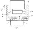
- the device located in air or another gas atmosphere has a trough 1, the trough floor of which forms a material carrier 2, which is transparent or translucent at least in a partial area 3.
- This partial area 3 of the material carrier covers at least the extent of the area that can be irradiated by the exposure unit 4 , the exposure unit 4 being arranged below the material carrier 2 .
- the exposure unit 4 has a light source (not shown) and a light modulator with which the intensity can be controlled by a control unit and adjusted in a location-selective manner in order to generate an exposure field on the material carrier 2 with the geometry desired for the layer to be formed at the moment.
- a laser can also be used in the exposure unit, the light beam of which successively scans the exposure field with the desired intensity pattern via a movable mirror that is controlled by a control unit.
- a construction platform 5 is provided above the material carrier 2 opposite the exposure unit 4 and is supported by a lifting mechanism, not shown, so that it is held in a height-adjustable manner above the material carrier 2 in the area above the exposure unit 4 .
- the construction platform 5 can also be transparent or translucent.
- a bath of highly viscous photopolymerizable material 6 is located on the material carrier 2.
- the material level 7 of the bath is defined by a suitable element, such as a squeegee, which applies the material evenly to the material carrier 2 in a specific material layer thickness a.
- the trough 1 can, for example, be assigned a guide rail on which a carriage is guided so that it can be displaced in the direction of the double arrow 8 .
- a drive ensures the back and forth movement of the carriage, which has a holder for a squeegee.
- the holder has, for example, a guide and an adjustment device in order to adjust the squeegee in the direction of the double arrow 9 in the vertical direction.
- the distance between the lower edge of the squeegee and the material carrier 2 can thus be adjusted.
- the squeegee comes to Use when the build platform moves as in 1 shown is in the raised state, and serves to distribute the material 6 evenly while setting a predetermined layer thickness.
- the layer thickness of the material 6 resulting from the material distribution process is defined by the distance between the lower edge of the squeegee and the material carrier 2 .
- the resulting material layer thickness a is greater than the component layer thickness b ( 2 ).
- the procedure for defining a layer of photopolymerizable material is as follows.
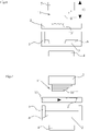
- the construction platform 5, on which component layers 10', 10" and 10"' have already been formed, is, as in 2 shown, lowered in a controlled manner by the lifting mechanism, so that the underside of the lowest component layer 10"' first touches the surface of the material 6 with height a, then dips in and approaches the material carrier 2 to such an extent that between the underside of the lowest component layer 10"' and the material carrier 2 has exactly the desired component layer thickness b.
- photopolymerizable material is displaced from the space between the underside of the bottom component layer 10"' and the material carrier 2.
- the construction platform 5 is raised again by means of the lifting mechanism, which in 3 state shown.
- the photopolymerizable material 6 is no longer present in the exposed area.
- the device therefore comprises a material removal unit 12, as shown in FIGS Figures 4 to 11 shown.
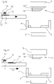
- the 4 shows the device before the formation of the device layer 10"".
- the material removal unit 12 is positioned in its starting position next to the tub 1 and is in the direction of the arrow 14 ( figure 5 ) moveable in horizontal direction.
- Adhering material 13 is now at least partially removed after the component layer 10′′′′ has been formed, in that the material removal unit 12 is initially moved between the component 11 and the tub 1 with the construction platform 5 raised.
- the component layer 10"" produced last and the material removal unit 12 are then brought into contact by a relative movement in the direction of arrow 15, so that the uncured quantity of material 13 adhering to the underside and possibly to the side surface of the bottom component layer 10"" is at least partially removed is transferred to the material removal unit 12 so that the Amount of material 13' reaches the material removal unit 12, as in 6 is shown.
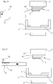
- the amount of material 13' is transferred to the material removal unit 12, for example, by the capillary action of an absorbent material of the material removal unit 12.
- a relative movement then takes place in order to separate the component from the material removal unit.
- a surface section of the material removal unit 12 is moved a little further in order to transport the removed amount of material away from the component layer 10"" and to provide a new surface section of the material removal unit 12 for a further material removal step, as in FIG 7 shown.
- the material removing unit 12 is returned to its original position ( 8 ), so that a further component layer 10"'" can be formed, to which in turn a quantity of material 13" adheres ( 9 ).
- the material removal unit 12 is moved between the component 11 and the tub 1 for the next material removal step and the material quantity 13'" is transferred to the material removal unit 12 as previously described ( 10 ).
- the material removing unit 12 is brought to its home position ( 11 ) and the next component layer can be created.
- the material removal unit 12 has an applicator 16 for a liquid, such as a solvent.
- a liquid such as a solvent.
- the liquid is on the applied to the surface of the material removal unit 12 so that a saturated layer 17 is formed ( 13 ).
- the adhering quantity of material 13 is subsequently at least partially transferred from the component layer with the aid of the layer 17 ( 15 ) so that the quantity of material 13 ′ reaches the material removal unit 12 .
- the material removal unit 12 or a separate unit is used to apply particles 19 to the cleaned component layer 10"" before the next component layer is produced.
- an applicator 18 is provided for this purpose, which applies particles 19 to the material removal unit 12 ( 18 ).
- the applicator 16 preferably also applies a liquid, so that a saturated layer 17 is formed.
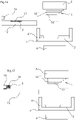
- Figures 22 to 31 show an example of a method with which a device layer can be produced from two different photopolymerizable materials.
- a modified device is used which, in comparison to the previous examples, has a second material trough 20 with a material carrier 21 in which a second material 22 is accommodated.
- a first component layer 10'" is formed by immersing the component in the one in the tub 1 Material 6 and curing of the material 6 produced ( 23 ). After lifting the component 11 ( 24 ) a quantity of material 13 again adheres to the component layer 10"" last built up, and as already described, the quantity of material 13' is transferred to the material removal unit 12 ( 25 and 26 ). In 26 it can be seen that the component layer 10"" leaves a portion 23 of the component layer 10'" uncovered. In this portion 23, a layer of the second material 22 is now produced by first removing the first trough 1 horizontally and instead placing the second trough 20 between the component 11 and the exposure unit 4 is arranged ( 27 ).
- the component 11 is immersed in the second material 22 until the previously produced component layer 10 touches the material carrier 2, so that a material layer is formed in the partial area 23, which is hardened ( 28 ). Since the adhering amount of material 13 of the first material 6 is at least partially transferred to the material removal unit 12 beforehand, so that the amount of material 13′ reaches the material removal unit 12, material 6 is prevented from mixing with the material 22 when it is immersed in the trough 20. Furthermore, it is avoided that the previously adhering amount of material 13 is also hardened by the last-mentioned formation and falsifies the geometry to be formed.
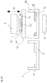
- the material removal unit 12 comprises a traveling belt 25 which is unwound from a supply roll 26 and wound onto the receiver roll 27.
- the movable belt 25 can consist of an absorbent material, in particular based on cellulose.
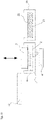
- Figure 33 shows an alternative embodiment of the material removal unit 12, with which the adhering quantity of material 13 is at least partially removed or sucked off pneumatically.
- the material removal unit 12 comprises a first channel 30 for a gas that generates a negative pressure at the mouth of the channel 32 by utilizing the Venturi effect.
- Another channel 31 opens out on the surface of the material removal unit 12 and generates a gas jet directed against the amount of material 13 adhering.
- an overpressure is also generated on the underside of the component, in that a gas pressure is generated via bores 33 (or other cavities) formed in the component 11 and the construction platform 5, which adhering amount of material 13 towards the channel 32 passes.
Landscapes
- Engineering & Computer Science (AREA)
- Chemical & Material Sciences (AREA)
- Materials Engineering (AREA)
- Manufacturing & Machinery (AREA)
- Optics & Photonics (AREA)
- Mechanical Engineering (AREA)
- Physics & Mathematics (AREA)
- Ceramic Engineering (AREA)
- Civil Engineering (AREA)
- Composite Materials (AREA)
- Structural Engineering (AREA)
- Health & Medical Sciences (AREA)
- Toxicology (AREA)
Priority Applications (2)
| Application Number | Priority Date | Filing Date | Title |
|---|---|---|---|
| EP20020586.2A EP4008523B1 (fr) | 2020-12-03 | 2020-12-03 | Procédé et dispositif de construction en couches d'un composant en matière photopolymerisable |
| US17/538,772 US20220176626A1 (en) | 2020-12-03 | 2021-11-30 | Method and device for building up a component in layers from photopolymerizable material |
Applications Claiming Priority (1)
| Application Number | Priority Date | Filing Date | Title |
|---|---|---|---|
| EP20020586.2A EP4008523B1 (fr) | 2020-12-03 | 2020-12-03 | Procédé et dispositif de construction en couches d'un composant en matière photopolymerisable |
Publications (3)
| Publication Number | Publication Date |
|---|---|
| EP4008523A1 true EP4008523A1 (fr) | 2022-06-08 |
| EP4008523B1 EP4008523B1 (fr) | 2023-11-29 |
| EP4008523C0 EP4008523C0 (fr) | 2023-11-29 |
Family
ID=73726532
Family Applications (1)
| Application Number | Title | Priority Date | Filing Date |
|---|---|---|---|
| EP20020586.2A Active EP4008523B1 (fr) | 2020-12-03 | 2020-12-03 | Procédé et dispositif de construction en couches d'un composant en matière photopolymerisable |
Country Status (2)
| Country | Link |
|---|---|
| US (1) | US20220176626A1 (fr) |
| EP (1) | EP4008523B1 (fr) |
Families Citing this family (2)
| Publication number | Priority date | Publication date | Assignee | Title |
|---|---|---|---|---|
| US20240033993A1 (en) * | 2022-07-28 | 2024-02-01 | General Electric Company | Systems and methods for additive manufacturing |
| CN115816826B (zh) * | 2022-09-30 | 2025-07-01 | 上海普利生三维科技有限公司 | 混合多材料三维打印方法及系统 |
Citations (8)
| Publication number | Priority date | Publication date | Assignee | Title |
|---|---|---|---|---|
| WO2010045950A1 (fr) | 2008-10-20 | 2010-04-29 | Ivoclar Vivadent Ag | Dispositif et procédé de traitement d’un matériau photopolymérisable permettant la réalisation par couches de corps moulés |
| EP2505341A1 (fr) | 2011-03-29 | 2012-10-03 | Ivoclar Vivadent AG | Procédé de montage en couche d'un corps de formage en matériau photopolymérisable hautement visqueux |
| US20150165695A1 (en) * | 2013-12-13 | 2015-06-18 | Xyzprinting, Inc. | Three dimensional printing apparatus |
| US20170072635A1 (en) * | 2011-01-31 | 2017-03-16 | Global Filtration Systems, A Dba Of Gulf Filtration Systems Inc. | Method and apparatus for making three-dimensional objects from multiple solidifiable materials |
| US20170182708A1 (en) * | 2015-12-09 | 2017-06-29 | Autodesk, Inc. | Multi-material stereolithographic three dimensional printing |
| WO2019190902A1 (fr) * | 2018-03-27 | 2019-10-03 | Carbon, Inc. | Procédés de revêtement de surface fonctionnelle pour produits fabriqués par fabrication additive |
| EP3621186A1 (fr) * | 2018-09-05 | 2020-03-11 | VAF GmbH | Dispositif de nettoyage et procédé de nettoyage d'un corps revêtu trempé |
| WO2020138617A1 (fr) | 2018-12-27 | 2020-07-02 | 한국기계연구원 | Appareil de lavage de structure d'impression 3d et procédé de lavage de structure d'impression 3d l'utilisant |
Family Cites Families (2)
| Publication number | Priority date | Publication date | Assignee | Title |
|---|---|---|---|---|
| WO2019204095A1 (fr) * | 2018-04-20 | 2019-10-24 | Carbon, Inc. | Méthodes de revêtement de surface liée pour produits fabriqués par fabrication additive |
| EP3969245A4 (fr) * | 2019-05-17 | 2023-01-25 | Holo, Inc. | Procédés et systèmes d'impression tridimensionnelle par stéréolithographie |
-
2020
- 2020-12-03 EP EP20020586.2A patent/EP4008523B1/fr active Active
-
2021
- 2021-11-30 US US17/538,772 patent/US20220176626A1/en not_active Abandoned
Patent Citations (9)
| Publication number | Priority date | Publication date | Assignee | Title |
|---|---|---|---|---|
| WO2010045950A1 (fr) | 2008-10-20 | 2010-04-29 | Ivoclar Vivadent Ag | Dispositif et procédé de traitement d’un matériau photopolymérisable permettant la réalisation par couches de corps moulés |
| US20170072635A1 (en) * | 2011-01-31 | 2017-03-16 | Global Filtration Systems, A Dba Of Gulf Filtration Systems Inc. | Method and apparatus for making three-dimensional objects from multiple solidifiable materials |
| EP2505341A1 (fr) | 2011-03-29 | 2012-10-03 | Ivoclar Vivadent AG | Procédé de montage en couche d'un corps de formage en matériau photopolymérisable hautement visqueux |
| US20150165695A1 (en) * | 2013-12-13 | 2015-06-18 | Xyzprinting, Inc. | Three dimensional printing apparatus |
| US20170182708A1 (en) * | 2015-12-09 | 2017-06-29 | Autodesk, Inc. | Multi-material stereolithographic three dimensional printing |
| WO2019190902A1 (fr) * | 2018-03-27 | 2019-10-03 | Carbon, Inc. | Procédés de revêtement de surface fonctionnelle pour produits fabriqués par fabrication additive |
| EP3621186A1 (fr) * | 2018-09-05 | 2020-03-11 | VAF GmbH | Dispositif de nettoyage et procédé de nettoyage d'un corps revêtu trempé |
| WO2020138617A1 (fr) | 2018-12-27 | 2020-07-02 | 한국기계연구원 | Appareil de lavage de structure d'impression 3d et procédé de lavage de structure d'impression 3d l'utilisant |
| US20210101342A1 (en) | 2018-12-27 | 2021-04-08 | Korea Institute Of Machinery & Materials | Cleaning apparatus for 3d printing structure and cleaning method for 3d printing structure using the same |
Also Published As
| Publication number | Publication date |
|---|---|
| US20220176626A1 (en) | 2022-06-09 |
| EP4008523B1 (fr) | 2023-11-29 |
| EP4008523C0 (fr) | 2023-11-29 |
Similar Documents
| Publication | Publication Date | Title |
|---|---|---|
| EP2855119B1 (fr) | Procédé destiné à la création d'un objet tridimensionnel | |
| DE69623213T2 (de) | Verfahren und Anlage zum Düsebeschichten | |
| EP3277481B1 (fr) | Procédé et dispositif de fabrication additive d'un corps | |
| DE19957370C2 (de) | Verfahren und Vorrichtung zum Beschichten eines Substrates | |
| EP3277482B1 (fr) | Procédé et dispositif de fabrication additive d'un corps | |
| EP0026538B1 (fr) | Dispositif pour le revêtement d'un écran d'impression | |
| WO2014012764A1 (fr) | Dispositif et procédé de fabrication par couches d'un objet tridimensionnel | |
| EP0739704A1 (fr) | Dispositif pour produire un objet par stéréolithographie | |
| DE102012021284B4 (de) | Vorrichtung und Verfahren zur schichtweisen Herstellung von Bauteilen mittels Photopolymerisation | |
| EP4008523B1 (fr) | Procédé et dispositif de construction en couches d'un composant en matière photopolymerisable | |
| DE3511124C2 (fr) | ||
| EP0897796A1 (fr) | Procédé de fabrication d'un gabarit de sérigraphie et dispositif à cet effet | |
| WO2021151777A1 (fr) | Imprimante 3d pour la fabrication additive d'une pièce et procédé d'impression | |
| WO1998008144A1 (fr) | Procede et dispositif pour l'application de photoresist sur des surfaces de substrat non planes | |
| DE3012988A1 (de) | Vorrichtung und verfahren zur herstellung eines druckplattenrohlings | |
| WO2018146287A1 (fr) | Procédé et dispositif de fabrication d'un objet moulé tridimensionnel par apport de matière par couches | |
| WO1996014203A1 (fr) | Procede et dispositif pour la production d'un objet a trois dimensions | |
| DE102009024334B4 (de) | Vorrichtung und Verfahren zur Beschickung einer Materialschicht auf eine Bauplattform oder auf wenigstens eine auf der Bauplattform befindlichen Materialschicht zur Herstellung eines Gegenstandes im Wege eines generativen Herstellungsverfahrens | |
| DE10159084A1 (de) | Druckform für den Hoch- oder Tiefdruck sowie Verfahren zu ihrer Herstellung | |
| DE102019110567A1 (de) | Haftmittelauftragseinrichtung | |
| DE102022105589A1 (de) | System und verfahren zur additiven fertigung von dreidimensional (3d) gedruckten objekten mit uv-gehärtetem material unter verwendung eines porösen substrats | |
| DE102024101731B3 (de) | Anordnung und Verfahren für den Bad-basierten 3D-Druck | |
| EP4188680A1 (fr) | Procédé de production d'un article façonné en 3d et dispositif utilisant un plateau perforé | |
| WO2017032760A1 (fr) | Procédé et dispositif d'application d'une structure sur un substrat rigide | |
| WO1995009078A1 (fr) | Procede et dispositif de production d'un objet tridimensionnel |
Legal Events
| Date | Code | Title | Description |
|---|---|---|---|
| PUAI | Public reference made under article 153(3) epc to a published international application that has entered the european phase |
Free format text: ORIGINAL CODE: 0009012 |
|
| STAA | Information on the status of an ep patent application or granted ep patent |
Free format text: STATUS: THE APPLICATION HAS BEEN PUBLISHED |
|
| AK | Designated contracting states |
Kind code of ref document: A1 Designated state(s): AL AT BE BG CH CY CZ DE DK EE ES FI FR GB GR HR HU IE IS IT LI LT LU LV MC MK MT NL NO PL PT RO RS SE SI SK SM TR |
|
| STAA | Information on the status of an ep patent application or granted ep patent |
Free format text: STATUS: REQUEST FOR EXAMINATION WAS MADE |
|
| 17P | Request for examination filed |
Effective date: 20221201 |
|
| RBV | Designated contracting states (corrected) |
Designated state(s): AL AT BE BG CH CY CZ DE DK EE ES FI FR GB GR HR HU IE IS IT LI LT LU LV MC MK MT NL NO PL PT RO RS SE SI SK SM TR |
|
| TPAC | Observations filed by third parties |
Free format text: ORIGINAL CODE: EPIDOSNTIPA |
|
| RIC1 | Information provided on ipc code assigned before grant |
Ipc: B22F 7/08 20060101ALI20230608BHEP Ipc: B29C 64/194 20170101ALI20230608BHEP Ipc: B29C 64/236 20170101ALI20230608BHEP Ipc: B29C 64/241 20170101ALI20230608BHEP Ipc: B29C 64/321 20170101ALI20230608BHEP Ipc: B29C 64/35 20170101ALI20230608BHEP Ipc: B33Y 10/00 20150101ALI20230608BHEP Ipc: B33Y 30/00 20150101ALI20230608BHEP Ipc: B33Y 40/00 20200101ALI20230608BHEP Ipc: B22F 10/00 20210101ALI20230608BHEP Ipc: B22F 12/00 20210101ALI20230608BHEP Ipc: B33Y 70/10 20200101ALI20230608BHEP Ipc: B08B 1/00 20060101ALI20230608BHEP Ipc: B29C 64/124 20170101AFI20230608BHEP |
|
| GRAP | Despatch of communication of intention to grant a patent |
Free format text: ORIGINAL CODE: EPIDOSNIGR1 |
|
| STAA | Information on the status of an ep patent application or granted ep patent |
Free format text: STATUS: GRANT OF PATENT IS INTENDED |
|
| INTG | Intention to grant announced |
Effective date: 20230717 |
|
| GRAS | Grant fee paid |
Free format text: ORIGINAL CODE: EPIDOSNIGR3 |
|
| GRAA | (expected) grant |
Free format text: ORIGINAL CODE: 0009210 |
|
| STAA | Information on the status of an ep patent application or granted ep patent |
Free format text: STATUS: THE PATENT HAS BEEN GRANTED |
|
| AK | Designated contracting states |
Kind code of ref document: B1 Designated state(s): AL AT BE BG CH CY CZ DE DK EE ES FI FR GB GR HR HU IE IS IT LI LT LU LV MC MK MT NL NO PL PT RO RS SE SI SK SM TR |
|
| REG | Reference to a national code |
Ref country code: GB Ref legal event code: FG4D Free format text: NOT ENGLISH |
|
| REG | Reference to a national code |
Ref country code: CH Ref legal event code: EP |
|
| REG | Reference to a national code |
Ref country code: DE Ref legal event code: R096 Ref document number: 502020006164 Country of ref document: DE |
|
| REG | Reference to a national code |
Ref country code: IE Ref legal event code: FG4D Free format text: LANGUAGE OF EP DOCUMENT: GERMAN |
|
| U01 | Request for unitary effect filed |
Effective date: 20231206 |
|
| U07 | Unitary effect registered |
Designated state(s): AT BE BG DE DK EE FI FR IT LT LU LV MT NL PT SE SI Effective date: 20231212 |
|
| U20 | Renewal fee for the european patent with unitary effect paid |
Year of fee payment: 4 Effective date: 20231207 |
|
| PG25 | Lapsed in a contracting state [announced via postgrant information from national office to epo] |
Ref country code: GR Free format text: LAPSE BECAUSE OF FAILURE TO SUBMIT A TRANSLATION OF THE DESCRIPTION OR TO PAY THE FEE WITHIN THE PRESCRIBED TIME-LIMIT Effective date: 20240301 |
|
| PG25 | Lapsed in a contracting state [announced via postgrant information from national office to epo] |
Ref country code: IS Free format text: LAPSE BECAUSE OF FAILURE TO SUBMIT A TRANSLATION OF THE DESCRIPTION OR TO PAY THE FEE WITHIN THE PRESCRIBED TIME-LIMIT Effective date: 20240329 |
|
| PG25 | Lapsed in a contracting state [announced via postgrant information from national office to epo] |
Ref country code: ES Free format text: LAPSE BECAUSE OF FAILURE TO SUBMIT A TRANSLATION OF THE DESCRIPTION OR TO PAY THE FEE WITHIN THE PRESCRIBED TIME-LIMIT Effective date: 20231129 |
|
| PG25 | Lapsed in a contracting state [announced via postgrant information from national office to epo] |
Ref country code: IS Free format text: LAPSE BECAUSE OF FAILURE TO SUBMIT A TRANSLATION OF THE DESCRIPTION OR TO PAY THE FEE WITHIN THE PRESCRIBED TIME-LIMIT Effective date: 20240329 Ref country code: GR Free format text: LAPSE BECAUSE OF FAILURE TO SUBMIT A TRANSLATION OF THE DESCRIPTION OR TO PAY THE FEE WITHIN THE PRESCRIBED TIME-LIMIT Effective date: 20240301 Ref country code: ES Free format text: LAPSE BECAUSE OF FAILURE TO SUBMIT A TRANSLATION OF THE DESCRIPTION OR TO PAY THE FEE WITHIN THE PRESCRIBED TIME-LIMIT Effective date: 20231129 |
|
| PG25 | Lapsed in a contracting state [announced via postgrant information from national office to epo] |
Ref country code: RS Free format text: LAPSE BECAUSE OF FAILURE TO SUBMIT A TRANSLATION OF THE DESCRIPTION OR TO PAY THE FEE WITHIN THE PRESCRIBED TIME-LIMIT Effective date: 20231129 Ref country code: PL Free format text: LAPSE BECAUSE OF FAILURE TO SUBMIT A TRANSLATION OF THE DESCRIPTION OR TO PAY THE FEE WITHIN THE PRESCRIBED TIME-LIMIT Effective date: 20231129 Ref country code: NO Free format text: LAPSE BECAUSE OF FAILURE TO SUBMIT A TRANSLATION OF THE DESCRIPTION OR TO PAY THE FEE WITHIN THE PRESCRIBED TIME-LIMIT Effective date: 20240229 Ref country code: HR Free format text: LAPSE BECAUSE OF FAILURE TO SUBMIT A TRANSLATION OF THE DESCRIPTION OR TO PAY THE FEE WITHIN THE PRESCRIBED TIME-LIMIT Effective date: 20231129 |
|
| PG25 | Lapsed in a contracting state [announced via postgrant information from national office to epo] |
Ref country code: CZ Free format text: LAPSE BECAUSE OF FAILURE TO SUBMIT A TRANSLATION OF THE DESCRIPTION OR TO PAY THE FEE WITHIN THE PRESCRIBED TIME-LIMIT Effective date: 20231129 |
|
| PG25 | Lapsed in a contracting state [announced via postgrant information from national office to epo] |
Ref country code: SK Free format text: LAPSE BECAUSE OF FAILURE TO SUBMIT A TRANSLATION OF THE DESCRIPTION OR TO PAY THE FEE WITHIN THE PRESCRIBED TIME-LIMIT Effective date: 20231129 |
|
| PG25 | Lapsed in a contracting state [announced via postgrant information from national office to epo] |
Ref country code: SM Free format text: LAPSE BECAUSE OF FAILURE TO SUBMIT A TRANSLATION OF THE DESCRIPTION OR TO PAY THE FEE WITHIN THE PRESCRIBED TIME-LIMIT Effective date: 20231129 Ref country code: SK Free format text: LAPSE BECAUSE OF FAILURE TO SUBMIT A TRANSLATION OF THE DESCRIPTION OR TO PAY THE FEE WITHIN THE PRESCRIBED TIME-LIMIT Effective date: 20231129 Ref country code: RO Free format text: LAPSE BECAUSE OF FAILURE TO SUBMIT A TRANSLATION OF THE DESCRIPTION OR TO PAY THE FEE WITHIN THE PRESCRIBED TIME-LIMIT Effective date: 20231129 Ref country code: CZ Free format text: LAPSE BECAUSE OF FAILURE TO SUBMIT A TRANSLATION OF THE DESCRIPTION OR TO PAY THE FEE WITHIN THE PRESCRIBED TIME-LIMIT Effective date: 20231129 |
|
| REG | Reference to a national code |
Ref country code: CH Ref legal event code: PL |
|
| U1N | Appointed representative for the unitary patent procedure changed after the registration of the unitary effect |
Representative=s name: SONN PATENTANWAELTE GMBH & CO KG; AT |
|
| PG25 | Lapsed in a contracting state [announced via postgrant information from national office to epo] |
Ref country code: MC Free format text: LAPSE BECAUSE OF FAILURE TO SUBMIT A TRANSLATION OF THE DESCRIPTION OR TO PAY THE FEE WITHIN THE PRESCRIBED TIME-LIMIT Effective date: 20231129 |
|
| PG25 | Lapsed in a contracting state [announced via postgrant information from national office to epo] |
Ref country code: MC Free format text: LAPSE BECAUSE OF FAILURE TO SUBMIT A TRANSLATION OF THE DESCRIPTION OR TO PAY THE FEE WITHIN THE PRESCRIBED TIME-LIMIT Effective date: 20231129 |
|
| REG | Reference to a national code |
Ref country code: DE Ref legal event code: R097 Ref document number: 502020006164 Country of ref document: DE |
|
| PLBE | No opposition filed within time limit |
Free format text: ORIGINAL CODE: 0009261 |
|
| STAA | Information on the status of an ep patent application or granted ep patent |
Free format text: STATUS: NO OPPOSITION FILED WITHIN TIME LIMIT |
|
| REG | Reference to a national code |
Ref country code: IE Ref legal event code: MM4A |
|
| PG25 | Lapsed in a contracting state [announced via postgrant information from national office to epo] |
Ref country code: IE Free format text: LAPSE BECAUSE OF NON-PAYMENT OF DUE FEES Effective date: 20231203 |
|
| PG25 | Lapsed in a contracting state [announced via postgrant information from national office to epo] |
Ref country code: CH Free format text: LAPSE BECAUSE OF NON-PAYMENT OF DUE FEES Effective date: 20231231 |
|
| PG25 | Lapsed in a contracting state [announced via postgrant information from national office to epo] |
Ref country code: IE Free format text: LAPSE BECAUSE OF NON-PAYMENT OF DUE FEES Effective date: 20231203 Ref country code: CH Free format text: LAPSE BECAUSE OF NON-PAYMENT OF DUE FEES Effective date: 20231231 |
|
| 26N | No opposition filed |
Effective date: 20240830 |
|
| U20 | Renewal fee for the european patent with unitary effect paid |
Year of fee payment: 5 Effective date: 20241107 |
|
| PG25 | Lapsed in a contracting state [announced via postgrant information from national office to epo] |
Ref country code: CY Free format text: LAPSE BECAUSE OF FAILURE TO SUBMIT A TRANSLATION OF THE DESCRIPTION OR TO PAY THE FEE WITHIN THE PRESCRIBED TIME-LIMIT; INVALID AB INITIO Effective date: 20201203 |
|
| PG25 | Lapsed in a contracting state [announced via postgrant information from national office to epo] |
Ref country code: HU Free format text: LAPSE BECAUSE OF FAILURE TO SUBMIT A TRANSLATION OF THE DESCRIPTION OR TO PAY THE FEE WITHIN THE PRESCRIBED TIME-LIMIT; INVALID AB INITIO Effective date: 20201203 |
|
| GBPC | Gb: european patent ceased through non-payment of renewal fee |
Effective date: 20241203 |
|
| PG25 | Lapsed in a contracting state [announced via postgrant information from national office to epo] |
Ref country code: GB Free format text: LAPSE BECAUSE OF NON-PAYMENT OF DUE FEES Effective date: 20241203 |
|
| U20 | Renewal fee for the european patent with unitary effect paid |
Year of fee payment: 6 Effective date: 20251104 |
|
| PG25 | Lapsed in a contracting state [announced via postgrant information from national office to epo] |
Ref country code: TR Free format text: LAPSE BECAUSE OF FAILURE TO SUBMIT A TRANSLATION OF THE DESCRIPTION OR TO PAY THE FEE WITHIN THE PRESCRIBED TIME-LIMIT Effective date: 20231129 |