EP2505742A2 - Kühlturm - Google Patents
Kühlturm Download PDFInfo
- Publication number
- EP2505742A2 EP2505742A2 EP12162232A EP12162232A EP2505742A2 EP 2505742 A2 EP2505742 A2 EP 2505742A2 EP 12162232 A EP12162232 A EP 12162232A EP 12162232 A EP12162232 A EP 12162232A EP 2505742 A2 EP2505742 A2 EP 2505742A2
- Authority
- EP
- European Patent Office
- Prior art keywords
- cooling tower
- column
- cooling
- tower according
- motor
- Prior art date
- Legal status (The legal status is an assumption and is not a legal conclusion. Google has not performed a legal analysis and makes no representation as to the accuracy of the status listed.)
- Granted
Links
- 238000001816 cooling Methods 0.000 title claims abstract description 128
- 239000012530 fluid Substances 0.000 claims abstract description 28
- 125000006850 spacer group Chemical class 0.000 claims description 13
- 230000003028 elevating effect Effects 0.000 abstract 1
- 239000007788 liquid Substances 0.000 description 22
- 238000010276 construction Methods 0.000 description 18
- 230000005540 biological transmission Effects 0.000 description 14
- 239000003570 air Substances 0.000 description 11
- 238000009434 installation Methods 0.000 description 9
- XLYOFNOQVPJJNP-UHFFFAOYSA-N water Substances O XLYOFNOQVPJJNP-UHFFFAOYSA-N 0.000 description 9
- 239000012080 ambient air Substances 0.000 description 6
- 230000003068 static effect Effects 0.000 description 5
- 241000736911 Turritella communis Species 0.000 description 4
- 238000013016 damping Methods 0.000 description 4
- 239000000725 suspension Substances 0.000 description 4
- 239000002253 acid Substances 0.000 description 2
- 239000004567 concrete Substances 0.000 description 2
- 230000002950 deficient Effects 0.000 description 2
- 239000000463 material Substances 0.000 description 2
- 230000003584 silencer Effects 0.000 description 2
- 229910000831 Steel Inorganic materials 0.000 description 1
- 238000010521 absorption reaction Methods 0.000 description 1
- 230000000712 assembly Effects 0.000 description 1
- 238000000429 assembly Methods 0.000 description 1
- 230000015572 biosynthetic process Effects 0.000 description 1
- 239000002826 coolant Substances 0.000 description 1
- 230000007547 defect Effects 0.000 description 1
- 238000004519 manufacturing process Methods 0.000 description 1
- 239000003595 mist Substances 0.000 description 1
- 239000002245 particle Substances 0.000 description 1
- 239000011150 reinforced concrete Substances 0.000 description 1
- 230000002787 reinforcement Effects 0.000 description 1
- 239000011343 solid material Substances 0.000 description 1
- 239000007921 spray Substances 0.000 description 1
- 239000010959 steel Substances 0.000 description 1
- 239000003351 stiffener Substances 0.000 description 1
Images




Classifications
-
- F—MECHANICAL ENGINEERING; LIGHTING; HEATING; WEAPONS; BLASTING
- F28—HEAT EXCHANGE IN GENERAL
- F28C—HEAT-EXCHANGE APPARATUS, NOT PROVIDED FOR IN ANOTHER SUBCLASS, IN WHICH THE HEAT-EXCHANGE MEDIA COME INTO DIRECT CONTACT WITHOUT CHEMICAL INTERACTION
- F28C1/00—Direct-contact trickle coolers, e.g. cooling towers
- F28C1/02—Direct-contact trickle coolers, e.g. cooling towers with counter-current only
-
- E—FIXED CONSTRUCTIONS
- E04—BUILDING
- E04H—BUILDINGS OR LIKE STRUCTURES FOR PARTICULAR PURPOSES; SWIMMING OR SPLASH BATHS OR POOLS; MASTS; FENCING; TENTS OR CANOPIES, IN GENERAL
- E04H5/00—Buildings or groups of buildings for industrial or agricultural purposes
- E04H5/10—Buildings forming part of cooling plants
- E04H5/12—Cooling towers
-
- F—MECHANICAL ENGINEERING; LIGHTING; HEATING; WEAPONS; BLASTING
- F28—HEAT EXCHANGE IN GENERAL
- F28F—DETAILS OF HEAT-EXCHANGE AND HEAT-TRANSFER APPARATUS, OF GENERAL APPLICATION
- F28F25/00—Component parts of trickle coolers
-
- F—MECHANICAL ENGINEERING; LIGHTING; HEATING; WEAPONS; BLASTING
- F28—HEAT EXCHANGE IN GENERAL
- F28F—DETAILS OF HEAT-EXCHANGE AND HEAT-TRANSFER APPARATUS, OF GENERAL APPLICATION
- F28F25/00—Component parts of trickle coolers
- F28F25/10—Component parts of trickle coolers for feeding gas or vapour
-
- F—MECHANICAL ENGINEERING; LIGHTING; HEATING; WEAPONS; BLASTING
- F28—HEAT EXCHANGE IN GENERAL
- F28F—DETAILS OF HEAT-EXCHANGE AND HEAT-TRANSFER APPARATUS, OF GENERAL APPLICATION
- F28F2250/00—Arrangements for modifying the flow of the heat exchange media, e.g. flow guiding means; Particular flow patterns
- F28F2250/08—Fluid driving means, e.g. pumps, fans
-
- Y—GENERAL TAGGING OF NEW TECHNOLOGICAL DEVELOPMENTS; GENERAL TAGGING OF CROSS-SECTIONAL TECHNOLOGIES SPANNING OVER SEVERAL SECTIONS OF THE IPC; TECHNICAL SUBJECTS COVERED BY FORMER USPC CROSS-REFERENCE ART COLLECTIONS [XRACs] AND DIGESTS
- Y02—TECHNOLOGIES OR APPLICATIONS FOR MITIGATION OR ADAPTATION AGAINST CLIMATE CHANGE
- Y02B—CLIMATE CHANGE MITIGATION TECHNOLOGIES RELATED TO BUILDINGS, e.g. HOUSING, HOUSE APPLIANCES OR RELATED END-USER APPLICATIONS
- Y02B30/00—Energy efficient heating, ventilation or air conditioning [HVAC]
- Y02B30/70—Efficient control or regulation technologies, e.g. for control of refrigerant flow, motor or heating
Definitions
- the invention relates to a cooling tower with a fluid cooling device and an axial fan, the axial fan is arranged in the height direction of the cooling tower above the fluid cooling device and supported by an anchored in the foundation of the cooling tower column, wherein the axial fan designed as a unit engine-transmission arrangement and a Fan wheel, wherein the fan wheel is arranged in the height direction of the cooling tower above the engine-gearbox assembly.
- Cooling towers are known from the prior art per se, such as from the WO 2009/149954 A1 , They serve to cool a fluid, such as a liquid, wherein the cooling takes place according to the principle of Verkowstungskühlung.
- the fluid to be cooled may be water.
- acid cooling towers in use, which serve the cooling of acid.
- Cooling towers of the aforementioned type are used in particular to cool liquids, preferably water by means of ambient air.
- known cooling towers have a fluid cooling device, which in turn has cooling installations and a liquid distribution device.
- the liquid to be cooled is sprayed above the cooling installations by means of the liquid distribution device and trickles down along the cooling installations, following the gravitational pull downwards.
- the cooling internals are preferably flowed through in countercurrent to the liquid to be cooled by air for the purpose of cooling. As a result of the contact of the liquid to be cooled with the air within the cooling installations, the cooling of the liquid to be cooled takes place as intended.
- an axial fan is provided. This is arranged in the height direction of the cooling tower above the fluid cooling device. During operation, the axial fan sucks from below the fluid cooling device ambient air, which flows as cooling air arranged in the height direction of the cooling tower below the axial fan fluid cooling device. The sucked in by the axial fan ambient air is released after flowing through the cooling installations upwards as heated ambient air to the atmosphere.
- an axial fan is used, in contrast to vorerläuterten WO 2009/149954 A1 has an axial fan with a fan wheel, which is arranged in the height direction of the cooling tower above the engine-transmission arrangement of the axial fan.
- the engine-transmission arrangement described here is not designed as a structural unit. The engine is rather separated from the gearbox and is not supported by a centrally formed pillar, but by a crossbeam, which is supported on one end to the pillar and the other end to a housing construction. For force-transmitting connection between the engine and gearbox extending in the direction of the crossbar connecting shaft is provided.
- the motor is arranged in extension of the housing column directly above the same on the transverse support, which disadvantageously makes a relatively long connecting shaft between the engine on the one hand and the transmission on the other hand required.
- this construction is very complex, not repair friendly and prone to failure due to externally acting stresses, especially since the engine and parts of the connecting shaft between the engine and transmission from external influences are completely unprotected outside the cooling tower housing construction.
- a cooling tower of the type mentioned is proposed with the invention, which is characterized in that the arrangement of the engine-transmission assembly on the column, a connecting flange in the form of a plate is provided, which is arranged at a distance to a column on the upper side final flange plate, wherein the engine-transmission arrangement is arranged hanging on the connecting flange.
- the axial fan does not support itself against the cooling tower jacket. Rather, a column is provided which carries the axial fan and which is anchored in the foundation of the cooling tower.
- the embodiment according to the invention is advantageous, in particular for load transfer reasons. It is not uncommon for the engine-gearbox arrangement of an axial fan alone to weigh over one tonne. Added to this is the weight of the fan wheel. In addition to the static loads caused by the weight of the axial fan, dynamic loads result in the normal operating condition, which also have to be absorbed by the supporting structure provided for the axial fan. According to the prior art according to the WO 2009/149954 A1 provided arrangement, the support of an axial fan on thedeturmmantel done. In order to be able to absorb in particular the dynamic loads occurring during operation, the cooling tower jacket is to be dimensioned accordingly, in particular to reinforce.
- the embodiment according to the invention takes a different approach.
- a column is provided for the support of the axial fan.
- the column can also be referred to as a support post.
- the column absorbs both the static loads as well as the dynamic loads occurring in the intended use case and diverts this directly into the foundation of the cooling tower.
- the cooling tower shell and the supporting structure can be designed to be less strongly dimensioned. Due to this, a material saving of up to 10% can be achieved, which significantly reduces the overall costs for the cooling tower production.
- the embodiment of the invention is also advantageous insofar as that a simplified assembly and disassembly of the axial fan is possible, which saves time especially in case of repair. Individual components of the axial fan can be easily removed and replaced in the event of a defect.
- the allowed The construction according to the invention has an overall more compact construction, since the hitherto used suspension for the arrangement of the axial fan on cooling tower jacket completely eliminated. Due to this, the disadvantages associated with the static and dynamic loads of such a suspension can be avoided. It is also advantageous that with the inventive design transmitted vibrations of the fan to the cooling tower housing and the cooling tower structure are significantly reduced.
- the axial fan has a motor-gear arrangement and a fan wheel, wherein the fan wheel is arranged in the height direction of the cooling tower above the engine-gearbox assembly.
- the fan wheel is arranged hanging on the engine-transmission arrangement, whereby the engine-transmission arrangement contributes a significant contribution to the dynamic loads occurring in the case of use, not least because of their high weight, that readily one Ton and more.
- the construction according to the invention provides that the motor-gear arrangement of the axial fan is supported directly opposite the column. A reduction of the dynamic loads occurring in the intended use case can thereby be achieved in an advantageous manner.
- the motor-gear arrangement of the axial fan is designed as a structural unit and as such in the assembly or disassembly case manageable.
- a structural unit formed means that instead of a separately handled engine and a separately handled gear, a motor-gear unit is provided which is integrally formed. In case of repair, this unit can be flanged off the fan wheel in a simple manner and replaced by a new unit. Repair-related downtime of the cooling tower can be reduced to a minimum.
- the construction of the invention differs from such embodiments, according to which the engine-transmission arrangement does not form a structural unit, but rather a separate arrangement of the engine on the one hand and the transmission is provided on the other hand, such as with the already mentioned documents EP 0 413 409 B1 . EP 0 558 300 B1 and EP 0 168 525 B1 described.
- the inventive design compared to this prior art, in particular by the compact structure, which is both in the case of assembly and in the case of dismantling, for example, for repair purposes of considerable advantage, because not only the handling is simplified, but also the downtime especially in case of repair can be reduced to a minimum.
- a connecting flange in the form of a plate is used for the arrangement of the motor-gear arrangement on the column.
- This connection flange is spaced from a flange plate carried by the column.
- support struts which are formed for example in the form of spacers, which in turn are penetrated by threaded rods.
- This receiving space serves to receive the motor-gear arrangement, wherein it is provided that this is arranged hanging on the connecting flange. In this way, a damping-effective decoupling can be achieved.
- a disassembly in case of repair is particularly simple, since it is sufficient to solve the motor-gear assembly connecting with the connecting flange fasteners.
- fasteners may be provided in this context, for example screws.
- four screws may be sufficient for arranging the motor-gearbox assembly on the connecting flange, so that in case of repair, only these four screws for disassembly are to be solved.
- the spacers are penetrated by threaded rods, which on the one hand on the flange plate and supported on the other hand, on the connecting flange and claimed in the intended use case to train.
- the engine-gearbox assembly is arranged hanging on the connecting flange, optionally with the interposition of a damping element, such as a damping mat and / or the like. Due to the suspended arrangement of the engine-transmission arrangement, the dynamic loads occurring in the intended use case can be at least partially absorbed and absorbed, so that a reduced stress of the axial fan total supporting column takes place.
- the hanging arrangement is advantageous in that a disassembly of the engine-transmission arrangement can be made in the simplest possible way.
- the engine-gearbox assembly is bolted to the flange plate, for example.
- these screws are to be solved, which then allows a removal of the entire engine-gearbox arrangement.
- the connecting flange is supported with the interposition of support struts relative to the column-side flange plate.
- these support struts can be a frame construction, a linkage or the like.
- the connecting flange is formed spaced from the flange plate, wherein the spacing space forms the receiving space for the motor-gear assembly, so that it can be arranged according to the invention hanging on the connecting flange.
- the support struts are formed as spacers.
- each spacer sleeve is penetrated by a threaded rod, the is supported on one end on the flange plate and the other end on the connecting flange.
- a plurality of spacers may be provided. However, an embodiment according to which four such spacers are used is preferred.
- the arrangement of the motor-gear assembly on the connecting flange is preferably a mounting plate which is formed tantsflanschrig on the engine-gearbox assembly.
- the arrangement of the motor-gear arrangement can be done on the connecting flange with the interposition of a damping element.
- the motor-gear assembly is preferably bolted to the connecting flange, which allows a quick disassembly especially in case of repair.
- the pillar also called support pillar, penetrates according to a further feature of the invention, the fluid cooling device in the height direction.
- the column represents insofar a self-supporting construction. It is anchored on the one hand in the foundation of the cooling tower and carries on the other side the axial fan arranged thereon. Depending on the design of the column, in an alternative embodiment of the invention it may also be provided that parts of the fluid cooling device are supported on the column designed as a support post.
- the column has a feed pipe for the fluid supply to the fluid cooling device.
- the column may also be formed by the inlet pipe.
- the supply pipe of the fluid cooling device provided anyway for supplying liquid serves as a pillar for the supporting support of the axial fan.
- the design of the housing can be anyway Already provided inlet pipe should be sufficient to absorb the static and dynamic loads caused by an axial fan.
- reinforcements and / or stiffeners of the same can be provided for load absorption through the inlet pipe.
- the column support supporting the axial fan made of reinforced concrete wherein the inlet pipe for the fluid cooling device in the longitudinal direction of the column extending into this is integrated, for example as a steel or plastic pipe, or as a concrete channel. In the case of the concrete channel thereby the column is formed.
- the column closes according to a further feature of the invention on the upper side with a flange plate.
- This flange plate is preferably the releasable connection of the column with an axial fan.
- a support rod for the column is provided.
- the formation of such a support linkage serves in particular to intercept dynamic loads occurring during operation. It can be provided that the support rod pillars distanced to anchor in the foundation of the cooling tower and / or in the cooling tower shell.
- the dimensioning of the column may be smaller than compared to a construction without support rods. Depending on the application, it can therefore be provided to provide a support rod to reduce the dimensioning of the column or to dimension a support rod to be provided anyway.
- FIG. 6 shows a cooling tower 19, as in the prior art according to the WO 2009/149954 A1 is known.
- the cooling tower 19 has a fluid cooling device 27. This in turn has a diesstechniksverteil adopted 28 on the one hand and cooling fixtures 20 on the other.
- the liquid distribution device 28 is arranged at a height H above the cooling installations 20 or above a uniformly liquid to be acted upon cross-sectional area 38.
- the liquid distribution cross section 38 and the upper end surface of the cooling components 20 coincide.
- the liquid distribution device 28 has a plurality of distribution pipes 24, which are connected to the liquid side of a common inlet pipe 23.
- cooling tower 19 By the cooling tower 19 by means of a suction fan wheel 37 arranged as a cooling medium ambient air in accordance with the arrows 21 with respect to the drawing plane after FIG. 6 guided from bottom to top.
- the air 21 passes through the cooling assemblies 20, which are formed in three layers in the embodiment shown.
- the liquid to be cooled by means of the cooling tower 19, for example water, is introduced into the inlet pipe 23 via a feed line 22. From there it passes to the distribution pipes 24, which are equipped for the purpose of liquid outlet with tangentially scheduled full cone nozzles 1.
- the distance between the outlet openings of the full cone nozzles 1 and the upper edge of the cooling installations 20 determines the spray height H, which is for example 600 mm.
- the cooling tower 19 both air inlet side and air outlet side muffler 40 and 41 on.
- the fan wheel 37 is hanging on a motor-gear assembly 6 - also called geared motor - arranged.
- This motor-gear assembly 6 is supported in turn suspended from the cooling tower shell 8, for which purpose a suspension 10 formed from individual struts 11 is provided.
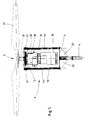
- FIGS. 1 to 5 The embodiment according to the invention is in the FIGS. 1 to 5 shown, the FIGS. 1 to 3 a first embodiment and the FIGS. 4 and 5 relate to a second embodiment.
- FIG. 1 can be seen in a schematic side view of a cooling tower assembly 9.
- Thisdeturman extract 9 has two cooling towers 19, which are each formed in accordance with the invention.
- a schematic side view of one of the two cooling towers 19 of the cooling tower assembly 9 is FIG. 2 refer to.
- FIG. 6 has a cooling tower 19 according to the invention via an axial fan 2, which is not suspended against thedeturmmantel 8 is supported.
- a column 4 is rather provided, which in turn is anchored in the foundation 3 of the cooling tower 19.
- “Anchored” within the meaning of the invention means not only a direct anchorage in the foundation of the cooling tower, but also an indirect anchorage under Interposition of further support elements.
- the column supporting the axial fan is in turn supported by supporting elements.
- the column can also be formed by these support elements.
- Such support elements may be columnar support bodies or the like which are anchored in the foundation of the cooling tower. It can be provided that the support elements on site use predetermined space, resulting in an overall compact and less bulky construction.
- the column 4 carries on the top side a flange plate 5. This serves the hereby releasably connecting the column 4 with the axial fan. 2
- the axial fan 2 is in turn formed from a motor-gear arrangement 6 and a fan wheel 37.
- the motor-gear assembly 6 is supported on the column 4.
- the fan wheel 37 in turn is supported on the motor-gear assembly 6, so that a total of a structure is reached, after which the fan wheel 37, in contrast to the prior art explained before FIG. 6 is arranged in the height direction 29 of the cooling tower 19 above the engine-transmission assembly 6.
- a support rod 7 may be provided. This is preferably anchored in the foundation 3 of the cooling tower 9. It consists of several frame struts 12, for example four, which are interconnected by braces 13. In this way, a framework is formed overall, which is able to absorb high static and dynamic loads with comparatively low material usage.
- the frame struts 12 of the support rod 7 engage via flange struts 14 with respect to the height direction 29 directly below the fan wheel 37 to the motor-gear assembly 6, in particular as shown FIG. 2 lets recognize.
- this is a direct outflow of the intended Use case occurring dynamic loads on the support rod 7 in the foundation 3 of the cooling tower 19 achieved.
- the column 4 can be formed by the inlet pipe 23 provided anyway for the purpose of supplying liquid to the liquid distribution device 28. In this way, a particularly compact embodiment of the invention is achieved.
- the column 4 terminates on the top side with a flange plate 5, as in particular the detailed representation according to FIG. 3 can be seen.
- angle plates 32 may be provided. Such angle plates 32 are particularly advantageous when the flange plate 5, as shown in the illustration FIG. 3 shown, has a larger cross-sectional diameter than the column 4.
- a connecting flange 15 is provided, which is also plate-shaped.
- the connecting flange 15 is supported relative to the flange plate 5 by means of support posts 16. These are formed in the embodiment shown as threaded rods which engage connecting flange side in the connection flange 15 carried threaded receptacles 17.
- the threaded rods 16 each pass through the spacing of connecting flange 15 and flange plate 5 serving spacers 44.
- the connecting flange 15 serves for hanging receiving the engine-transmission assembly 6.
- the transmission 18 of the motor-gear assembly 6 by means of a mounting plate 30 hanging arranged on the connecting flange 15.
- the motor 26 is arranged suspended, so that a total of a suspended arrangement of the motor-gear assembly 6 is achieved on the connecting flange 15.
- the drive shaft 31 for the fan wheel 37 protrudes from the gear 18, the connecting flange 15th
- FIGS. 4 and 5 show a second embodiment of the invention.
- the cooling tower 19 in the embodiment according to FIG. 4 has already described above a liquid distribution device 28.
- the liquid distribution device 28 is not supplied via a running in the interior of the cooling tower 19 inlet pipe with the fluid to be distributed. According to the embodiment shown here, rather, a lateral fluid supply via a feed tube 45 takes place Embodiment of the FIGS. 4 and 5 the column 4 also not as a feed pipe.
- the column 4 according to the embodiment according to the FIGS. 4 and 5 is designed as a pure support column. It can be configured as a tube or formed from solid material.
- Diagonal struts 42 For a supplementary support of the axial fan 2 are used in the embodiment shown in the FIGS. 4 and 5 Diagonal struts 42. These attack on the one hand on the engine-gear assembly 6 and on the other hand on the cooling tower shell 8. There are preferably four diagonal struts 42 are provided.
- mist eliminator 43 is provided below the engine-transmission assembly 6 in the embodiment of the FIGS. 4 and 5 . This is intended in particular to deposit fluid particles entrained by the axial fan 2 during operation from the conveyed air 21 and to drain it in the direction of the cooling components 20.
- FIG. 5 can be seen in a detailed view in particular the engine-transmission assembly 6. This corresponds to the reason of those after FIG. 3 ,
- a column 4 but not the inlet pipe 23 is used.
- the column is used in the embodiment shown exclusively as a support column of the support of the axial fan 2.
- the column 4 in the embodiment of the FIGS. 4 and 5 in diameter also designed smaller than that column 4 according to the embodiment according to the FIGS. 1 to 3 , Accordingly fall in the embodiment of the FIGS. 4 and 5 the angle plates 32 in their dimensions also larger.
- the basic principle is identical in both embodiments.
- the engine 26 and the transmission 18 of the engine-transmission assembly 6 are arranged one above the other in the height direction 29, wherein the transmission 18 is positioned in the height direction 29 above the motor 26.
- the invention is not limited to this arrangement of motor 26 and gear 18. It may also be provided in an alternative embodiment that the motor 26 is arranged above the transmission 18.
- a juxtaposed embodiment of motor 26 and gear 18 may be provided.
- the transmission is preferably flanged on the fan wheel 37. The motor 26 is juxtaposed to the transmission 18, wherein it, while avoiding a separate connecting shaft directly to the transmission 18th is flanged.
- the transmission 18 can also be dispensed with, in which case the motor 26 is coupled directly to the fan wheel 37.
- Such an application takes place, in particular, when it is possible to transmit the speed delivered by the engine to the fan wheel 37, so that a gearbox-related reduction of the engine speed is not required.
- FIG. 5 Incidentally, it can still be seen that spacer sleeves 44 are arranged between the flange plate 5 and the connecting flange 15. These spacers 44 are penetrated by the trained as threaded rods support posts 16. In the final assembled state, the support posts 16 to train and the spacers 44 are charged to pressure.
- the embodiment according to the invention can also be used in combination with so-called dry cooling towers.
- the fluid cooling device 27 is formed from a heat exchanger as an essential structural component. A trickling of water does not take place according to this variant.
- the invention is not limited to cooling towers that have a liquid distribution device.
Landscapes
- Engineering & Computer Science (AREA)
- Mechanical Engineering (AREA)
- General Engineering & Computer Science (AREA)
- Architecture (AREA)
- Physics & Mathematics (AREA)
- Thermal Sciences (AREA)
- Civil Engineering (AREA)
- Structural Engineering (AREA)
- Structures Of Non-Positive Displacement Pumps (AREA)
Abstract
Description
- Die Erfindung betrifft einen Kühlturm mit einer Fluidkühleinrichtung und einem Axialventilator, wobei der Axialventilator in Höhenrichtung des Kühlturms oberhalb der Fluidkühleinrichtung angeordnet und von einer im Fundament des Kühlturms verankerten Säule getragen ist, wobei der Axialventilator eine als eine Baueinheit ausgebildete Motor-Getriebe-Anordnung und ein Ventilatorrad aufweist, wobei das Ventilatorrad in Höhenrichtung des Kühlturms oberhalb der Motor-Getriebe-Anordnung angeordnet ist.
- Kühltürme sind aus dem Stand der Technik an sich bekannt, so zum Beispiel aus der
WO 2009/149954 A1 . Sie dienen der Abkühlung eines Fluides, beispielsweise einer Flüssigkeit, wobei die Abkühlung nach dem Prinzip der Verdünstungskühlung erfolgt. Bei dem abzukühlenden Fluid kann es sich um Wasser handeln. Es sind aber auch sogenannte Säurekühltürme gebräuchlich, welche der Abkühlung von Säure dienen. - Kühltürme der vorgenannten Art dienen insbesondere dazu, Flüssigkeiten, vorzugsweise Wasser mittels Umgebungsluft abzukühlen. Zu diesem Zweck verfügen vorbekannte Kühltürme über eine Fluidkühleinrichtung, die ihrerseits Kühleinbauten und eine Flüssigkeitsverteil-einrichtung aufweist. Die zu kühlende Flüssigkeit wird oberhalb der Kühleinbauten mittels der Flüssigkeitsverteileinrichtung versprüht und rieselt an den Kühleinbauten entlang, und zwar der Schwerkraft folgend nach unten. Dabei werden die Kühleinbauten vorzugsweise im Gegenstrom zur abzukühlenden Flüssigkeit von Luft zum Zwecke der Kühlung durchströmt. Infolge des Kontakts der abzukühlenden Flüssigkeit mit der Luft innerhalb der Kühleinbauten kommt es zur bestimmungsgemäßen Abkühlung der abzukühlenden Flüssigkeit.
- Um die als Kühlluft dienende Umgebungsluft in vorerläuterter Weise durch den Kühlturm zu führen, ist ein Axialventilator vorgesehen. Dieser ist in Höhenrichtung des Kühlturms oberhalb der Fluidkühleinrichtung angeordnet. Im Betriebsfall saugt der Axialventilator von unterhalb der Fluidkühleinrichtung Umgebungsluft an, die als Kühlluft die in Höhenrichtung des Kühlturms unterhalb des Axialventilators angeordnete Fluidkühleinrichtung durchströmt. Die vom Axialventilator angesaugte Umgebungsluft wird nach einem Durchströmen der Kühleinbauten nach oben als erwärmte Umgebungsluft an die Atmosphäre abgegeben.
- Aus dem Stand der Technik nach der
WO 2009/149954 A1 ist ein Axialventilator bekannt geworden, der eine als eine Baueinheit ausgebildete Motor-Getriebe-Anordnung sowie ein Ventilatorrad aufweist. Dabei stützt sich die Motor-Getriebe-Anordnung gegenüber der Kühlturmummantelung ab. Das Ventilatorrad ist hängend an der Motor-Getriebe-Anordnung angeordnet. - Aus dem Stand der Technik sind auch andere Bauformen bekannt geworden, so zum Beispiel aus der
EP 0 413 409 B1 . Gemäß der hier beschriebenen Konstruktion kommt ein Axialventilator zum Einsatz, der im Unterschied zur vorerläutertenWO 2009/149954 A1 über einen Axialventilator mit einem Ventilatorrad verfügt, das in Höhenrichtung des Kühlturms oberhalb der Motor-Getriebe-Anordnung des Axialventilators angeordnet ist. Die hier beschriebene Motor-Getriebe-Anordnung ist allerdings nicht als eine Baueinheit ausgebildet. Der Motor ist vielmehr vom Getriebe separiert und wird nicht von einer zentral ausgebildeten Säule, sondern von einem Querbalken getragen, der sich einendseitig an der Säule und anderendseitig an einer Gehäusekonstruktion abstützt. Zur kraftübertragenden Verbindung zwischen Motor und Getriebe ist eine in Richtung des Querbalkens verlaufende Verbindungswelle vorgesehen. Von Nachteil dieser Konstruktion ist insbesondere ihre Montage- bzw. Demontageunfreundlichkeit. Darüber hinaus ist sie in nachteiliger Weise entsprechend auszulegen und zu dimensionieren, damit die im Betriebsfall auftretenden Kräfte funktionssicher aufgenommen und unter anderem in die Gehäusekonstruktion abgeleitet werden können. - Aus der
EP 0 558 300 B1 ist eine im Vergleich zur vorgenanntenEP 0 413 409 B1 vergleichbare Lösung bekannt geworden. Auch hier wird eine Konstruktion mit einem Axialventilator vorgeschlagen, der über ein Ventilatorrad verfügt, das in Höhenrichtung des Kühlturms oberhalb der Motor-Getriebe-Anordnung des Axialventilators angeordnet ist. Die Motor-Getriebe-Anordnung ist indes nicht als eine Baueinheit ausgebildet und verfügt über einen separat zum Getriebe ausgebildeten Motor, der über eine Verbindungswelle mit dem Getriebe gekoppelt ist. Dabei ist der Motor von einer Querstütze getragen, die sich einendseitig an einer zentralen Säule und anderendseitig an einer Gehäusesäule abstützt. Dabei ist der Motor in Verlängerung der Gehäusesäule direkt oberhalb derselben an der Querstütze angeordnet, was in nachteiliger Weise eine verhältnismäßig lange Verbindungswelle zwischen Motor einerseits und Getriebe andererseits erforderlich macht. Insgesamt ist diese Konstruktion sehr aufwendig, nicht reparaturfreundlich und störanfällig aufgrund von von außen einwirkenden Beanspruchungen, da insbesondere der Motor und Teile der Verbindungswelle zwischen Motor und Getriebe vor äußeren Einflüssen völlig ungeschützt außerhalb der Kühlturmgehäusekonstruktion ausgebildet sind. - Aus der
US 4,976,985 ist eine weitere Konstruktionsalternative bekannt geworden. Gemäß der hier vorgeschlagenen Konstruktion kommt eine zentrale Säule zum Einsatz, die oberseitig eine Flanschplatte trägt. Auf dieser Flanschplatte ist ein aus einem Motor und einem Ventilatorrad gebildeter Axialventilator direkt angeordnet. Die direkte Anordnung des Axialventilators an der Flanschplatte der Säule ist insbesondere aus Belastungsgründen von Nachteil, da die während eines bestimmungsgemäßen Betriebes des Axialventilators auftretenden dynamischen Belastungen direkt in die Säule eingeleitet werden, was eine entsprechende Dimensionierung derselben erforderlich macht. - Eine weitere Offenbarung ergibt sich aus der
EP 0 168 525 B1 . Gemäß der hier beschriebenen Konstruktion kommt eine nicht als eine Baueinheit ausgebildete Motor-Getriebe-Anordnung zum Einsatz, was die schon anhand der vorzierten Druckschriften erläuterten Nachteile mit sich bringt. - Ausgehend vom Vorbeschriebenen ist es die Aufgabe der Erfindung, einen Kühlturm der eingangs genannten Art dahingehend weiterzuentwickeln, dass hinsichtlich der Ausgestaltung des Axialventilators ein vereinfachter Aufbau sowie eine vereinfachte Handhabung ermöglicht ist.
- Zur Lösung dieser Aufgabe wird mit der Erfindung ein Kühlturm der eingangs genannten Art vorgeschlagen, der sich dadurch auszeichnet, dass zur Anordnung der Motor-Getriebe-Anordnung an der Säule ein Verbindungsflansch in Form einer Platte vorgesehen ist, der beabstandet zu einer die Säule oberseitig abschließenden Flanschplatte angeordnet ist, wobei die Motor-Getriebe-Anordnung hängend am Verbindungsflansch angeordnet ist.
- Im Unterschied zum vorbekannten Stand der Technik nach der
WO 2009/149954 A1 stützt sich der Axialventilator nicht gegenüber der Kühlturmummantelung ab. Es ist vielmehr eine Säule vorgesehen, die den Axialventilator trägt und die im Fundament des Kühlturms verankert ist. - Die erfindungsgemäße Ausgestaltung ist insbesondere aus Lastabtragsgründen von Vorteil. Es ist keine Seltenheit, dass allein die Motor-Getriebe-Anordnung eines Axialventilators über eine Tonne wiegt. Hinzu kommt das Gewicht des Ventilatorrades. Neben dem durch das Gewicht des Axialventilators hervorgerufenen statischen Belastungen ergeben sich im bestimmungsgemäßen Betriebsfall dynamische Belastungen, die von der für den Axialventilator vorgesehenen Tragkonstruktion ebenfalls aufgenommen werden müssen. Gemäß der nach dem Stand der Technik gemäß der
WO 2009/149954 A1 vorgesehenen Anordnung erfolgt die Abstützung eines Axialventilators über den Kühlturmmantel. Um insbesondere die im Betriebsfall auftretenden dynamischen Belastungen aufnehmen zu können, ist der Kühlturmmantel entsprechend zu dimensionieren, insbesondere zu verstärken. - Die erfindungsgemäße Ausgestaltung geht einen anderen Weg. Für die Abstützung des Axialventilators ist eine Säule vorgesehen. Diese ist im Fundament des Kühlturms verankert und trägt oberseitig den Axialventilator. Die Säule kann insofern auch als Tragstütze bezeichnet werden. Die Säule nimmt sowohl die statischen Belastungen als auch die im bestimmungsgemäßen Verwendungsfall auftretenden dynamischen Belastungen auf und leitet dieses direkt ins Fundament des Kühlturmes ab. In der Konsequenz kann im Unterschied zum Stand der Technik der Kühlturmmantel sowie die tragende Struktur (Stützenwald) weniger stark dimensioniert ausgebildet sein. Aufgrund dessen kann eine Materialeinsparung von zum Teil 10 % erreicht werden, womit sich die Gesamtkosten für die Kühlturmerstellung insgesamt spürbar reduzieren. Die erfindungsgemäße Ausgestaltung ist darüber hinaus insofern von Vorteil, als dass eine vereinfachte Montage bzw. Demontage des Axialventilators ermöglicht ist, was insbesondere im Reparaturfall Zeit spart. Einzelkomponenten des Axialventilators können im Defektfall einfach ausgebaut und ausgetauscht werden. Darüber hinaus erlaubt die erfindungsgemäße Konstruktion einen insgesamt kompakteren Aufbau, da die bislang verwendete Aufhängung zur Anordnung des Axialventilators am Kühlturmmantel vollends entfällt. Aufgrund dessen können auch die mit den statischen und dynamischen Belastungen einer solchen Aufhängung einhergehenden Nachteile vermieden werden. Dabei ist ferner von Vorteil, dass mit der erfindungsgemäßen Ausgestaltung übertragene Schwingungen des Ventilators auf das Kühlturmgehäuse und die Kühlturmstruktur deutlich reduziert sind.
- Der Axialventilator weist eine Motor-Getriebe-Anordnung sowie ein Ventilatorrad auf, wobei das Ventilatorrad in Höhenrichtung des Kühlturms oberhalb der Motor-Getriebe-Anordnung angeordnet ist. Im Unterschied zum Stand der Technik beispielsweise nach der
WO 2009/149954 A1 ist die Höhenausrichtung von Motor-Getriebe-Anordnung einerseits und Venitilatorrad andererseits also umgekehrt. Nach diesem Stand der Technik ist das Ventilatorrad hängend an der Motor-Getriebe-Anordnung angeordnet, womit die Motor-Getriebe-Anordnung einen nicht unerheblichen Beitrag zu den im Verwendungsfall auftretenden dynamischen Belastungen beisteuert, nicht zuletzt auch aufgrund ihres hohen Gewichtes, dass ohne weiteres eine Tonne und mehr betragen kann. Die erfindungsgemäße Konstruktion sieht indes vor, dass sich die Motor-Getriebe-Anordnung des Axialventilators direkt gegenüber der Säule abstützt. Eine Reduzierung der im bestimmungsgemäßen Verwendungsfall auftretenden dynamischen Belastungen kann hierdurch in vorteilhafter Weise erreicht werden. - Die Motor-Getriebe-Anordnung des Axialventilators ist als eine Baueinheit ausgebildet und als solche im Montage- bzw. Demontagefall handhabbar.
- Als "eine Baueinheit" ausgebildet meint dabei, dass anstelle eines separat zu handhabenden Motors und eines separat zu handhabenden Getriebes eine Motor-Getriebe-Einheit vorgesehen ist, die integrativ ausgebildet ist. Im Reparaturfall kann diese Einheit vom Ventilatorrad in einfacher Weise abgeflanscht und durch eine neue Einheit ersetzt werden. Reparaturbedingte Ausfallzeiten des Kühlturms können so auf ein Minimum reduziert werden. Damit unterscheidet sich die erfindungsgemäße Konstruktion gegenüber solchen Ausgestaltungen, wonach die Motor-Getriebe-Anordnung keine Baueinheit bildet, sondern vielmehr eine getrennte Anordnung von Motor einerseits und Getriebe andererseits vorgesehen ist, wie zum Beispiel mit den schon eingangs genannten Dokumenten
EP 0 413 409 B1 ,EP 0 558 300 B1 undEP 0 168 525 B1 beschrieben. Damit bezeichnet sich die erfindungsgemäße Ausgestaltung gegenüber diesem Stand der Technik insbesondere durch den kompakten Aufbau aus, was sowohl im Falle der Montage als auch im Falle der Demontage beispielsweise zu Reparaturzwecken von erheblichem Vorteil ist, weil nicht nur die Handhabung vereinfacht ist, sondern auch die Ausfallzeiten insbesondere im Reparaturfall auf ein Minimum reduziert werden können. - Gemäß der Erfindung ist vorgesehen, dass zur Anordnung der Motor-Getriebe-Anordnung an der Säule ein Verbindungsflansch in Form einer Platte zum Einsatz kommt. Dieser Verbindungsflansch ist beabstandet zu einer von der Säule getragenen Flanschplatte angeordnet. Es können zu diesem Zweck Stützstreben vorgesehen sein, die beispielsweise in Form von Distanzhülsen ausgebildet sind, die ihrerseits von Gewindestangen durchgegriffen sind. Im endfertig montierten Zustand bilden die Flanschplatte und der Verbindungsflansch aufgrund ihrer beabstandeten Anordnung einen Aufnahmeraum zwischen sich aus. Dieser Aufnahmeraum dient der Aufnahme der Motor-Getriebe-Anordnung, wobei vorgesehen ist, dass diese hängend am Verbindungsflansch angeordnet ist. Auf diese Weise kann eine dämpfungswirksame Entkopplung erreicht werden. Darüber hinaus ist eine Demontage im Reparaturfall besonders einfach, da es hierfür ausreichend ist, die die Motor-Getriebe-Anordnung mit dem Verbindungsflansch verbindenden Befestigungsmittel zu lösen. Als Befestigungsmittel können in diesem Zusammenhang beispielsweise Schrauben vorgesehen sein. Je nach Dimensionierung können vier Schrauben zur Anordnung der Motor-Getriebe-Anordnung am Verbindungsflansch ausreichend sein, so dass im Reparaturfall lediglich diese vier Schrauben für eine Demontage zu lösen sind.
- Im Unterschied beispielsweise zur bereits vorgenannten
US 4,976,895 erfolgt nach der erfindungsgemäßen Ausgestaltung keine direkte Motoranordnung an einer von der Säule getragenen Flanschplatte. Es sind stattdessen vielmehr eine Flanschplatte einerseits und ein Verbindungsflansch andererseits vorgesehen. Dabei ist der als Platte ausgebildete Verbindungsflansch beabstandet zur Flanschplatte angeordnet, wobei der infolge der beabstandeten Anordnung ausgebildete Aufnahmeraum der Aufnahme der Motor-Getriebe-Anordnung dient. Zur beabstandeten Anordnung des Verbindungsflansches an der Flanschplatte kommen bevorzugter Weise Distanzhülsen zum Einsatz, die im bestimmungsgemäßen Verwendungsfall auf Druck belastet sind. Die Distanzhülsen sind von Gewindestangen durchgriffen, die sich einerseits an der Flanschplatte und andererseits am Verbindungsflansch abstützen und im bestimmungsgemäßen Verwendungsfall auf Zug beansprucht sind. Die Motor-Getriebe-Anordnung ist hängend am Verbindungsflansch angeordnet, gegebenenfalls unter Zwischenschaltung eines Dämpfungselements, beispielsweise einer Dämpfungsmatte und/oder dergleichen. Aufgrund der hängenden Anordnung der Motor-Getriebe-Anordnung können die im bestimmungsgemäßen Verwendungsfall auftretenden dynamischen Belastungen zumindest zum Teil aufgefangen und absorbiert werden, so dass eine verringerte Beanspruchung der den Axialventilator insgesamt tragenden Säule stattfindet. Darüber hinaus ist die hängende Anordnung insofern von Vorteil, als dass in denkbar einfacher Weise eine Demontage der Motor-Getriebe-Anordnung vorgenommen werden kann. - Die Motor-Getriebe-Anordnung ist beispielsweise mit der Flanschplatte verschraubt. Zum Zwecke der Demontage beispielsweise im Reparaturfall sind diese Schrauben zu lösen, was als dann eine Entnahme der gesamten Motor-Getriebe-Anordnung gestattet. Auf diese Weise ist es in einfacher Weise möglich, eine defekte Motor-Getriebe-Anordnung gegen eine neue zu tauschen, was die Ausfallzeit des Kühlturmes auf ein Minimum reduziert. Nach einem Austausch der defekten Motor-Getriebe-Anordnung kann diese dann hinsichtlich ihrer technischen Funktionstätigkeit überprüft und gegebenenfalls repariert werden.
- Insgesamt wird mit der erfindungsgemäßen Konstruktion eine Anordnung vorgeschlagen, die gegenüber dem Stand der Technik vereinfacht ist und zwar sowohl im Aufbau als auch in der Handhabung und die darüber hinaus vergleichsweise kostengünstig ist.
- Es ist gemäß einem weiteren Merkmal der Erfindung vorgesehen, dass sich der Verbindungsflansch unter Zwischenordnung von Stützstreben gegenüber der säulenseitigen Flanschplatte abstützt. Bei diesen Stützstreben kann es sich im einfachsten Fall um eine Rahmenkonstruktion, ein Gestänge oder dergleichen handeln. Von erfindungswesentlicher Bedeutung ist, dass der Verbindungsflansch beabstandet zur Flanschplatte ausgebildet ist, wobei der Beabstandungsraum den Aufnahmeraum für die Motor-Getriebe-Anordnung ausbildet, so dass diese in erfindungsgemäßer Weise hängend am Verbindungsflansch angeordnet werden kann.
- Gemäß einer bevorzugten Ausführungsform sind die Stützstreben als Distanzhülsen ausgebildet. Dabei ist eine jede Distanzhülse von einer Gewindestange durchgriffen, die sich einendseitig an der Flanschplatte und anderendseitig am Verbindungsflansch abstützt. Je nach Größe und Gewicht der Motor-Getriebe-Anordnung und/oder des Ventilatorrades können eine Mehrzahl von Distanzhülsen vorgesehen sein. Bevorzugt ist indes eine Ausgestaltungsform, gemäß der vier solcher Distanzhülsen zum Einsatz kommen.
- Gemäß einem weiteren Merkmal der Erfindung ist vorgesehen, dass zur zusätzlichen Abstützung der Flanschplatte gegenüber der Säule Winkelbleche vorgesehen sind. Dabei bestimmt sich die Größe und Anzahl der vorzusehenden Winkelbleche nach der abzufangenden Traglast einerseits und der Größe der Flanschplatte in Relation zum Durchmesser der Säule andererseits.
- Zur Anordnung der Motor-Getriebe-Anordnung am Verbindungsflansch dient bevorzugter Weise eine Befestigungsplatte, die verbindungsflanschseitig an der Motor-Getriebe-Anordnung ausgebildet ist. Dabei kann die Anordnung der Motor-Getriebe-Anordnung am Verbindungsflansch unter Zwischenordnung eines Dämpfungselements erfolgen.
- Die Motor-Getriebe-Anordnung ist bevorzugter Weise mit dem Verbindungsflansch verschraubt, das insbesondere im Reparaturfall eine schnelle Demontage gestattet.
- Die Säule, auch Tragstütze genannt, durchragt gemäß einem weiteren Merkmal der Erfindung die Fluidkühleinrichtung in Höhenrichtung. Die Säule stellt insofern eine selbsttragende Konstruktion dar. Sie ist einerseits im Fundament des Kühlturms verankert und trägt anderendseitig den darauf angeordneten Axialventilator. Je nach Ausgestaltung der Säule kann in einer alternativen Ausgestaltung der Erfindung auch vorgesehen sein, dass sich Teile der Fluidkühleinrichtung an der als Tragstütze ausgebildeten Säule mit abstützen.
- Gemäß einem besonderen Vorschlag der Erfindung ist vorgesehen, dass die Säule ein Zulaufrohr für die Fluidzuführung zur Fluidkühleinrichtung aufweist. Gegebenenfalls kann die Säule auch durch das Zulaufrohr gebildet sein. In jedem Fall wird mit dieser besonderen Ausgestaltung eine sehr kompakte Bauform sowie eine Multifunktionalität erreicht. Das ohnehin zur Flüssigkeitszuführung vorgesehene Zulaufrohr der Fluidkühleinrichtung dient als Säule zur tragenden Abstützung des Axialventilators. Dabei kann je nach Dimensionierung des Kühlturms die Ausgestaltung des ohnehin vorgesehenen Zulaufrohrs bereits ausreichend sein, die von einem Axialventilator hervorgerufenen statischen und dynamischen Belastungen aufzunehmen. Gegebenenfalls können zur Belastungsaufnahme durch das Zulaufrohr auch Verstärkungen und/oder Aussteifungen desselben vorgesehen sein.
- Zur Aufnahme vergleichsweise hoher Belastungen kann auch vorgesehen sein, die Säule zu tragenden Abstützung des Axialventilators aus Stahlbeton zu bilden, wobei das Zulaufrohr für die Fluidkühleinrichtung in Längsrichtung der Säule verlaufend in diese integriert ist, beispielsweise als Stahl- oder Kunststoffrohr, oder auch als Betonkanal. Im Falle des Betonkanals wird hierdurch die Säule gebildet.
- Die Säule schließt gemäß einem weiteren Merkmal der Erfindung oberseitig mit einer Flanschplatte ab. Diese Flanschplatte dient bevorzugter Weise der lösbaren Verbindung der Säule mit einem Axialventilator.
- Gemäß einem weiteren Merkmal der Erfindung ist ein Stützgestänge für die Säule vorgesehen. Die Ausbildung eines solchen Stützgestänges dient insbesondere dazu, im Betriebsfall auftretende dynamische Belastungen abzufangen. Dabei kann vorgesehen sein, dass Stützgestänge säulenentfernt im Fundament des Kühlturms und/oder im Kühlturmmantel zu verankern.
- Je nach Dimensionierung des Stützgestänges kann die Dimensionierung der Säule geringer ausfallen als im Vergleich zu einer Konstruktion ohne Stützgestänge. Je nach Anwendungsfall kann also vorgesehen sein, zur Reduzierung der Dimensionierung der Säule ein Stützgestänge vorzusehen oder ein ohnehin vorzusehendes Stützgestänge entsprechend zu dimensionieren.
- Weitere Vorteile und Merkmale der Erfindung ergeben sich aus der nachfolgenden Beschreibung anhand der Figuren. Dabei zeigen
- Figur 1
- in schematischer Seitenansicht eine Kühlturmanordnung mit zwei Kühltürmen nach der Erfindung;
- Figur 2
- die Kühlturmanordnung nach
Figur 1 gemäß Sichtrichtung II nachFigur 1 ; - Figur 3
- in einer Detailansicht eine Motor-Getriebe-Anordnung gemäß Ausschnitt III nach
Figur 2 ; - Figur 4
- in schematische Darstellung einen Kühlturm nach der Erfindung in Seitenansicht gemäß einer zweiten Ausführungsform;
- Figur 5
- in einer Detailansicht die Motor-Getriebe-Anordnung nach
Figur 4 und - Figur 6
- in schematischer Seitenansicht einen Kühlturm nach dem Stand der Technik.
-
Figur 6 zeigt einen Kühlturm 19, wie er aus dem Stand der Technik nach derWO 2009/149954 A1 bekannt ist. Der Kühlturm 19 weist einen Fluidkühleinrichtung 27 auf. Diese verfügt ihrerseits über eine Flüssigkeitsverteileinrichtung 28 einerseits und Kühleinbauten 20 andererseits. In Höhenrichtung 29 des Kühlturms 19 ist die Flüssigkeitsverteileinrichtung 28 in einer Höhe H oberhalb der Kühleinbauten 20 bzw. oberhalb einer gleichmäßig mit Flüssigkeit zu beaufschlagenden Querschnittsfläche 38 angeordnet. Im gezeigten Ausführungsbeispiel nachFigur 6 fallen der Flüssigkeitsverteilquerschnitt 38 und die obere Abschlussfläche der Kühleinbauten 20 zusammen. - Die Flüssigkeitsverteileinrichtung 28 verfügt über eine Mehrzahl von Verteilerrohren 24, die an ein gemeinsames Zulaufrohr 23 flüssigkeitsseitig angeschlossen sind.
- Durch den Kühlturm 19 wird mittels eines saugend angeordneten Ventilatorrades 37 als Kühlmedium Umgebungsluft in Entsprechung der Pfeile 21 mit Bezug auf die Zeichnungsebene nach
Figur 6 von unten nach oben geführt. Im Zuge des Hindurchführens der Luft 21 durch den Kühlturm 19 passiert die Luft 21 die Kühleinbauten 20, die im gezeigten Ausführungsbeispiel dreilagig ausgebildet sind. - Die mittels des Kühlturmes 19 abzukühlende Flüssigkeit, beispielsweise Wasser, wird über eine Zuführleitung 22 in das Zulaufrohr 23 eingeleitet. Von dort aus gelangt es zu den Verteilerrohren 24, die zum Zwecke des Flüssigkeitsaustritts mit tangential angesetzten Vollkegeldüsen 1 ausgerüstet sind. Der Abstand zwischen den Austrittsöffnungen der Vollkegeldüsen 1 und der oberen Kante der Kühleinbauten 20 bestimmt die Sprühhöhe H, welche beispielsweise 600 mm beträgt.
- Das gleichmäßig über den Kühleinbauten 20 verteilte Warmwasser 25 durchrieselt diese im hier gezeigten Fall im Gegenstrom zur von unten nach oben beförderten Kühlluft 21.
- Das nach einem Durchrieseln der Kühleinbauten 20 abgekühlte Warmwasser 25 tropft aus den Kühleinbauten 20 ab und wird in der Wassersammelwanne 39 aufgefangen und von dort zu den zu kühlenden Anlagen weitergeführt.
- Zur Schalldämpfung weist der Kühlturm 19 sowohl lufteintrittsseitig als auch luftaustrittsseitig Schalldämpfer 40 und 41 auf.
- Wie die Darstellung nach
Figur 6 erkennen lässt, ist das Ventilatorrad 37 hängend an einer Motor-Getriebe-Anordnung 6 - auch Getriebemotor genannt - angeordnet. Diese Motor-Getriebe-Anordnung 6 stützt sich ihrerseits hängend am Kühlturmmantel 8 ab, zu welchem Zweck eine aus einzelnen Streben 11 gebildete Aufhängung 10 vorgesehen ist. - Die Ausgestaltung nach der Erfindung ist in den
Figuren 1 bis 5 gezeigt, wobei dieFiguren 1 bis 3 eine erste Ausführungsform und dieFiguren 4 und5 eine zweite Ausführungsform betreffen. -
Figur 1 lässt in schematischer Seitenansicht eine Kühlturmanordnung 9 erkennen. Diese Kühlturmanordnung 9 verfügt über zwei Kühltürme 19, die jeweils in erfindungsgemäßer Weise ausgebildet sind. Eine schematische Seitenansicht auf einen der beiden Kühltürme 19 der Kühlturmanordnung 9 istFigur 2 zu entnehmen. - Im Unterschied zum vorerläuterten Stand der Technik nach
Figur 6 verfügt ein Kühlturm 19 nach der Erfindung über einen Axialventilator 2, der sich nicht hängend gegenüber dem Kühlturmmantel 8 abstützt. Zur Anordnung des Axialventilators 2 ist vielmehr eine Säule 4 vorgesehen, die ihrerseits im Fundament 3 des Kühlturms 19 verankert ist. - "Verankert" im Sinne der Erfindung meint dabei nicht nur eine direkte Verankerung im Fundament des Kühlturms, sondern auch eine indirekte Verankerung unter Zwischenschaltung weiterer Stützelemente. In diesem Sinn kann insbesondere aufgrund baulicher Gegebenheiten mit Blick insbesondere auf die Fluidkühleinrichtung vorgesehen sein, dass die den Axialventilator abstützende Säule ihrerseits durch Stützelemente getragen ist. Die Säule kann durch diese Stützelemente auch gebildet sein. Bei solchen Stützelementen kann es sich um säulenartige Stützkörper oder ähnliches handeln, die im Fundament des Kühlturmes verankert sind. Dabei kann vorgesehen sein, dass die Stützelemente bauseits vorgegebene Bauräume ausnutzen, was insgesamt zu einer kompakten und wenig ausladenden Konstruktion führt.
- Die Säule 4 trägt oberseitig eine Flanschplatte 5. Diese dient der insbesonderen lösbaren Verbindung der Säule 4 mit dem Axialventilator 2.
- Der Axialventilator 2 ist seinerseits aus einer Motor-Getriebe-Anordnung 6 und einem Ventilatorrad 37 gebildet. Gemäß der erfindungsgemäßen Ausgestaltung stützt sich die Motor-Getriebe-Anordnung 6 auf der Säule 4 ab. Das Ventilatorrad 37 stützt sich seinerseits auf der Motor-Getriebe-Anordnung 6 ab, so dass insgesamt ein Aufbau erreicht ist, wonach das Ventilatorrad 37 im Unterschied zum vorerläuterten Stand der Technik nach
Figur 6 in Höhenrichtung 29 des Kühlturms 19 oberhalb der Motor-Getriebe-Anordnung 6 angeordnet ist. - Die Darstellungen nach den
Figuren 2 und3 lassen weitere Details der Erfindung erkennen. - Für eine zusätzliche Abstützung insbesondere gegenüber im bestimmungsgemäßen Verwendungsfall auftretenden dynamischen Belastungen kann ein Stützgestänge 7 vorgesehen sein. Dieses ist vorzugsweise im Fundament 3 des Kühlturms 9 verankert. Es besteht aus mehreren Gerüststreben 12, beispielsweise vier, die untereinander durch Verstrebungen 13 miteinander verbunden sind. Auf diese Weise wird insgesamt ein Fachwerk ausgebildet, das unter vergleichsweise geringem Materialeinsatz auch hohe statische und dynamische Belastungen aufzunehmen in der Lage ist.
- Die Gerüststreben 12 des Stützgestänges 7 greifen über Flanschstreben 14 mit Bezug auf die Höhenrichtung 29 direkt unterhalb des Ventilatorrades 37 an der Motor-Getriebe-Anordnung 6 an, wie insbesondere die Darstellung nach
Figur 2 erkennen lässt. In vorteilhafter Weise wird hierdurch ein direkter Abfluss der im bestimmungsgemäßen Verwendungsfall auftretenden dynamischen Belastungen über das Stützgestänge 7 in das Fundament 3 des Kühlturms 19 erreicht. - Die Säule 4 kann gemäß dem in den Figuren gezeigten Beispiel durch das zum Zwecke der Flüssigkeitszufuhr zur Flüssigkeitsverteileinrichtung 28 ohnehin vorgesehene Zulaufrohr 23 gebildet sein. Auf diese Weise wird eine besonders kompakte Ausgestaltung der Erfindung erreicht.
- Die Säule 4 schließt oberseitig mit einer Flanschplatte 5 ab, wie dies insbesondere der Detaildarstellung nach
Figur 3 zu entnehmen ist. Für eine zusätzliche Abstützung der Flanschplatte 5 können Winkelbleche 32 vorgesehen sein. Derartige Winkelbleche 32 sind insbesondere dann von Vorteil, wenn die Flanschplatte 5, wie in der Darstellung nachFigur 3 gezeigt, einen größeren Querschnittsdurchmesser als die Säule 4 aufweist. Zur Flanschplatte 5 beabstandet ist ein Verbindungsflansch 15 vorgesehen, der gleichfalls plattenförmig ausgebildet ist. Der Verbindungsflansch 15 stützt sich gegenüber der Flanschplatte 5 mittels Tragstützen 16 ab. Diese sind im gezeigten Ausführungsbeispiel als Gewindestangen ausgebildet, die verbindungsflanschseitig in vom Verbindungsflansch 15 getragene Gewindeaufnahmen 17 eingreifen. Dabei durchgreifen die Gewindestangen 16 jeweils der Abstandshaltung von Verbindungsflansch 15 und Flanschplatte 5 dienende Distanzhülsen 44. Der Verbindungsflansch 15 dient der hängenden Aufnahme der Motor-Getriebe-Anordnung 6. Dabei ist das Getriebe 18 der Motor-Getriebe-Anordnung 6 mittels einer Befestigungsplatte 30 hängend am Verbindungsflansch 15 angeordnet. Am Getriebe 18 ist wiederum der Motor 26 hängend angeordnet, so dass insgesamt eine hängende Anordnung der Motor-Getriebe-Anordnung 6 am Verbindungsflansch 15 erreicht ist. Die Antriebswelle 31 für das Ventilatorrad 37 durchragt ausgehend vom Getriebe 18 den Verbindungsflansch 15. - Die
Figuren 4 und5 zeigen eine zweite Ausführungsform der Erfindung. - Der Kühlturm 19 in der Ausgestaltung nach
Figur 4 verfügt in schon vorbeschriebener Weise über eine Flüssigkeitsverteileinrichtung 28. Im Unterschied zur vorbeschriebenen Ausgestaltungsform wird die Flüssigkeitsverteileinrichtung 28 jedoch nicht über ein im Innenraum des Kühlturms 19 verlaufendes Zulaufrohr mit dem zu verteilenden Fluid versorgt. Gemäß der hier dargestellten Ausführungsform erfolgt vielmehr eine seitliche Fluidzuführung über ein Zuführrohr 45. Dementsprechend dient bei dem Ausführungsbeispiel nach denFiguren 4 und5 die Säule 4 auch nicht als Zulaufrohr. - Die Säule 4 nach dem Ausführungsbeispiel gemäß den
Figuren 4 und5 ist als reine Stützsäule ausgebildet. Sie kann als Rohr ausgestaltet oder aus Vollmaterial gebildet sein. - Für eine ergänzende Abstützung des Axialventilators 2 dienen im gezeigten Ausführungsbeispiel nach den
Figuren 4 und5 Diagonalstreben 42. Diese greifen einerseits an der Motor-Getriebe-Anordnung 6 und andererseits am Kühlturmmantel 8 an. Es sind bevorzugterweise insgesamt vier Diagonalstreben 42 vorgesehen. - Unterhalb der Motor-Getriebe-Anordnung 6 ist bei dem Ausführungsbeispiel nach den
Figuren 4 und5 ein Tropfenabscheider 43 vorgesehen. Dieser soll insbesondere dazu dienen, vom Axialventilator 2 im Betriebsfall mitgerissene Fluidpartikel aus der geförderten Luft 21 abzuscheiden und in Richtung der Kühleinbauten 20 abtropfen zu lassen. -
Figur 5 lässt in einer Detailansicht insbesondere die Motor-Getriebe-Anordnung 6 erkennen. Diese entspricht dem Grunde nach derjenigen nachFigur 3 . Im Unterschied zur Ausgestaltung nachFigur 3 kommt als Säule 4 aber nicht das Zulaufrohr 23 zum Einsatz. Die Säule dient im gezeigten Ausführungsbeispiel ausschließlich als Stützsäule der Abstützung des Axialventilators 2. In der Konsequenz ist die Säule 4 in der Ausgestaltung nach denFiguren 4 und5 im Durchmesser auch geringer ausgestaltet als diejenige Säule 4 nach dem Ausführungsbeispiel gemäß denFiguren 1 bis 3 . Dementsprechend fallen bei der Ausgestaltung nach denFiguren 4 und5 die Winkelbleche 32 in ihrer Dimensionierung auch größer aus. Das Grundprinzip ist bei beiden Ausführungsformen aber identisch. - Bei der Ausführungsform nach
Figur 5 sind der Motor 26 und das Getriebe 18 der Motor-Getriebe-Anordnung 6 in Höhenrichtung 29 übereinander angeordnet, wobei das Getriebe 18 in Höhenrichtung 29 oberhalb des Motors 26 positioniert ist. Die Erfindung ist nicht auf diese Anordnung von Motor 26 und Getriebe 18 beschränkt. Es kann in einer alternativen Ausgestaltung auch vorgesehen sein, dass der Motor 26 oberhalb des Getriebes 18 angeordnet ist. Ferner kann auch eine nebengeordnete Ausgestaltung von Motor 26 und Getriebe 18 vorgesehen sein. In diesem Fall ist das Getriebe bevorzugterweise am Ventilatorrad 37 angeflanscht. Der Motor 26 ist dem Getriebe 18 nebengeordnet, wobei er unter Vermeidung einer separaten Verbindungswelle direkt an das Getriebe 18 angeflanscht ist. Gemäß einer dritten Alternative kann auf das Getriebe 18 auch verzichtet werden, wobei dann der Motor 26 direkt mit dem Ventilatorrad 37 gekoppelt ist. Eine solche Anwendung findet insbesondere dann statt, wenn es möglich ist, die vom Motor abgegebene Drehzahl auf das Ventilatorrad 37 zu übertragen, eine getriebetechnische Reduzierung der Motordrehzahl also nicht erforderlich ist. -
Figur 5 lässt im Übrigen noch erkennen, dass zwischen der Flanschplatte 5 und dem Verbindungsflansch 15 Distanzhülsen 44 angeordnet sind. Diese Distanzhülsen 44 sind von den als Gewindestangen ausgebildeten Tragstützen 16 durchgriffen. Im endmontierten Zustand werden die Tragstützen 16 auf Zug und die Distanzhülsen 44 auf Druck belastet. - Die erfindungsgemäße Ausgestaltung kann auch in Kombination mit sogenannten Trockenkühltürmen Verwendung finden. In diesem Fall ist die Fluidkühleinrichtung 27 aus einem Wärmetauscher als wesentliche Baukomponente gebildet. Eine Verrieselung von Wasser findet gemäß dieser Variante nicht statt. Die Erfindung ist insofern nicht auf Kühltürme beschränkt, die eine Flüssigkeitsverteileinrichtung aufweisen.
-
- 1
- Vollkegeldüse
- 2
- Axialventilator
- 3
- Fundament
- 4
- Säule
- 5
- Flanschplatte
- 6
- Motor-Getriebe-Anordnung
- 7
- Stützgestänge
- 8
- Kühlturmmantel
- 9
- Kühlturmanordnung
- 10
- Aufhängung
- 11
- Strebe
- 12
- Gerüststrebe
- 13
- Verstrebung
- 14
- Flanschstrebe
- 15
- Verbindungsflansch
- 16
- Tragstütze (Gewindestange)
- 17
- Gewindeaufnahme
- 18
- Getriebe
- 19
- Kühlturm
- 20
- Kühleinbauten
- 21
- Luft
- 22
- Zuführleitung
- 23
- Zulaufrohr
- 24
- Verteilrohr
- 25
- Warmwasser
- 26
- Motor
- 27
- Fluidkühleinrichtung
- 28
- Flüssigkeitsverteileinrichtung
- 29
- Höhenrichtung
- 30
- Befestigungsplatte
- 31
- Welle
- 32
- Winkelblech
- 37
- Ventilatorrad
- 38
- Flüssigkeitsverteilquerschnitt
- 39
- Wassersammelwanne
- 40
- Schalldämpfer
- 41
- Schalldämpfer
- 42
- Diagonalstrebe
- 43
- Tropfenabscheider
- 44
- Distanzhülse
- 45
- Zuführrohr
Claims (13)
- Kühlturm mit einer Fluidkühleinrichtung (27) und einem Axialventilator (2), wobei der Axialventilator (2) in Höhenrichtung (29) des Kühlturms (19) oberhalb der Fluidkühleinrichtung (27) angeordnet und von einer im Fundament (3) des Kühlturms (19) verankerten Säule (4) getragen ist, wobei der Axialventilator (2) eine als eine Baueinheit ausgebildete Motor-Getriebe-Anordnung (6) und ein Ventilatorrad (37) aufweist, wobei das Ventilatorrad (37) in Höhenrichtung (29) des Kühlturms (19) oberhalb der Motor-Getriebe-Anordnung (6) angeordnet ist, dadurch gekennzeichnet, dass zur Anordnung der Motor-Getriebe-Anordnung (6) an der Säule (4) ein Verbindungsflansch (15) in Form einer Platte vorgesehen ist, der beabstandet zu einer die Säule (4) oberseitig abschließenden Flanschplatte (5) angeordnet ist, wobei die Motor-Getriebe-Anordnung (6) hängend am Verbindungsflansch (15) angeordnet ist.
- Kühlturm nach Anspruch 1, dadurch gekennzeichnet, dass sich der Verbindungsflansch (15) unter Zwischenordnung von Stützstreben gegenüber der säulenseitigen Flanschplatte (5) abstützt.
- Kühlturm nach Anspruch 2, dadurch gekennzeichnet, dass eine Stützstrebe in Form einer Distanzhülse (44) ausgebildet ist.
- Kühlturm nach Anspruch 3, dadurch gekennzeichnet, dass eine Distanzhülse (44) von einer Gewindestange (16) durchgegriffen ist.
- Kühlturm nach Anspruch 4, dadurch gekennzeichnet, dass sich eine Gewindestange (16) kopfseitig gegenüber der Flanschplatte (5) abstützt und gewindeseitig in eine vom Verbindungsflansch (15) getragene Gewindeaufnahme (17) eingreift.
- Kühlturm nach einem der vorhergehenden Ansprüche, dadurch gekennzeichnet, dass für eine zusätzliche Abstützung der Flanschplatte (5) gegenüber der Säule (4) Winkelbleche (32) vorgesehen sind.
- Kühlturm nach einem der vorhergehenden Ansprüche, dadurch gekennzeichnet, dass die Motor-Getriebe-Anordnung (6) verbindungsflanschseitig eine Befestigungsplatte (30) aufweist.
- Kühlturm nach einem der vorhergehenden Ansprüche, dadurch gekennzeichnet, dass die Motor-Getriebe-Anordnung (6) mit dem Verbindungsflansch (15) verschraubt ist.
- Kühlturm nach einem der vorhergehenden Ansprüche, dadurch gekennzeichnet, dass die Säule (4) die Fluidkühleinrichtung (27) in Höhenrichtung (29) durchragt.
- Kühlturm nach einem der vorhergehenden Ansprüche, dadurch gekennzeichnet, dass die Säule (4) ein Zulaufrohr (23) für die Fluidzufuhr zur Fluidkühleinrichtung (27) aufweist.
- Kühlturm nach einem der vorhergehenden Ansprüche, gekennzeichnet durch ein Stützgestänge (7) für die Säule (4).
- Kühlturm nach Anspruch 11, dadurch gekennzeichnet, dass das Stützgestänge (7) säulenentfernt im Fundament (3) des Kühlturms (9) verankert ist.
- Kühlturm nach Anspruch 11, dadurch gekennzeichnet, dass das Stützgestänge (7) säulenentfernt im Kühlturmmantel (8) verankert ist.
Applications Claiming Priority (1)
| Application Number | Priority Date | Filing Date | Title |
|---|---|---|---|
| DE202011004539U DE202011004539U1 (de) | 2011-03-29 | 2011-03-29 | Kühlturm |
Publications (3)
| Publication Number | Publication Date |
|---|---|
| EP2505742A2 true EP2505742A2 (de) | 2012-10-03 |
| EP2505742A3 EP2505742A3 (de) | 2016-04-06 |
| EP2505742B1 EP2505742B1 (de) | 2016-11-23 |
Family
ID=44313598
Family Applications (1)
| Application Number | Title | Priority Date | Filing Date |
|---|---|---|---|
| EP12162232.8A Not-in-force EP2505742B1 (de) | 2011-03-29 | 2012-03-29 | Kühlturm |
Country Status (2)
| Country | Link |
|---|---|
| EP (1) | EP2505742B1 (de) |
| DE (1) | DE202011004539U1 (de) |
Families Citing this family (4)
| Publication number | Priority date | Publication date | Assignee | Title |
|---|---|---|---|---|
| DE102015011131A1 (de) * | 2015-08-31 | 2017-03-02 | Esg Mbh | Nasskühltürme mit Zugunterstützung durch Ventilatoren Verringerung der Emission von Tropfen und von Mikroorganismen |
| DE102016005146A1 (de) * | 2016-04-28 | 2017-11-02 | Dieter Wurz | Tropfenabscheider mit "online" - Reinigungsbedüsung für Nasskühltürme oder für Luftwaschtürme bei der Intensivtierhaltung |
| CN110108151B (zh) * | 2019-05-30 | 2024-02-06 | 中国电力工程顾问集团西北电力设计院有限公司 | 自然通风冷却塔及其加强型钢管混凝土x支柱 |
| DE102020107955A1 (de) | 2020-03-23 | 2021-09-23 | W & S Management Gmbh & Co. Kg | Strahlventilator zur Belüftung von Tunneln, Strahlventilatorsystem und Verfahren |
Citations (5)
| Publication number | Priority date | Publication date | Assignee | Title |
|---|---|---|---|---|
| EP0168525B1 (de) | 1984-07-17 | 1988-10-12 | Ceramic Cooling Tower Company | Kühlturm mit Betonträgerstruktur, Glaswolleplatten und einem von der Flüssigkeitsverteilungsvorrichtung gestützten Ventilator |
| US4976895A (en) | 1989-12-15 | 1990-12-11 | Ceramic Cooling Tower Company | Lightweight cooling tower with fan supported by a vertical liquid supply pipe |
| EP0413409B1 (de) | 1989-08-14 | 1994-06-01 | Baltimore Aircoil Company, Inc. | Strukturelle Säule und Turm |
| EP0558300B1 (de) | 1992-02-24 | 1998-07-22 | Baltimore Aircoil Company, Inc. | Konstruktionsaufbau |
| WO2009149954A1 (de) | 2008-06-13 | 2009-12-17 | Cts Cooling Tower Solutions Gmbh | Fluidkühleinrichtung für insbesondere kühltürme |
Family Cites Families (1)
| Publication number | Priority date | Publication date | Assignee | Title |
|---|---|---|---|---|
| FR2216540B1 (de) * | 1973-02-07 | 1977-04-22 | Berry Sa Ets |
-
2011
- 2011-03-29 DE DE202011004539U patent/DE202011004539U1/de not_active Expired - Lifetime
-
2012
- 2012-03-29 EP EP12162232.8A patent/EP2505742B1/de not_active Not-in-force
Patent Citations (5)
| Publication number | Priority date | Publication date | Assignee | Title |
|---|---|---|---|---|
| EP0168525B1 (de) | 1984-07-17 | 1988-10-12 | Ceramic Cooling Tower Company | Kühlturm mit Betonträgerstruktur, Glaswolleplatten und einem von der Flüssigkeitsverteilungsvorrichtung gestützten Ventilator |
| EP0413409B1 (de) | 1989-08-14 | 1994-06-01 | Baltimore Aircoil Company, Inc. | Strukturelle Säule und Turm |
| US4976895A (en) | 1989-12-15 | 1990-12-11 | Ceramic Cooling Tower Company | Lightweight cooling tower with fan supported by a vertical liquid supply pipe |
| EP0558300B1 (de) | 1992-02-24 | 1998-07-22 | Baltimore Aircoil Company, Inc. | Konstruktionsaufbau |
| WO2009149954A1 (de) | 2008-06-13 | 2009-12-17 | Cts Cooling Tower Solutions Gmbh | Fluidkühleinrichtung für insbesondere kühltürme |
Also Published As
| Publication number | Publication date |
|---|---|
| DE202011004539U1 (de) | 2011-06-09 |
| EP2505742B1 (de) | 2016-11-23 |
| EP2505742A3 (de) | 2016-04-06 |
Similar Documents
| Publication | Publication Date | Title |
|---|---|---|
| EP3201550B1 (de) | Anlage zur kondensation von dampf | |
| EP2505742B1 (de) | Kühlturm | |
| DE102018101344A1 (de) | Kühleinheit, Anlage und Verfahren | |
| DE202014104666U1 (de) | Anlage zur Kondensation von Dampf | |
| DE102008016539A1 (de) | Reinigungsvorrichtung für Lukos oder dergleichen Wärmetauscher | |
| EP0505786A1 (de) | Schwingungsdämpfende Halterung | |
| EP3472462A1 (de) | Modular aufgebaute windenergieanlage | |
| DE102013221681B4 (de) | Hybridturm einer Windturbine | |
| EP2940418B1 (de) | Flüssigkeitsverteileinrichtung | |
| EP2778011B1 (de) | Baugruppe für einen Behälter und Schienenfahrzeug mit einer Baugruppe für einen Behälter | |
| DE60103471T2 (de) | Wasserverteilerrohr | |
| EP1189005A1 (de) | Kondensatorhals zwischen einer Dampfturbine und einem Kondensator | |
| EP3242966B1 (de) | Spinnbalken zur herstellung von schmelzgesponnenen filamenten | |
| DE102010055452A1 (de) | Strömungsleitvorrichtung im Einlaufbereich eines abfallenden Flüssigkeitskanals | |
| EP3981662A1 (de) | Fahrzeugkühlanlage | |
| DE69225237T2 (de) | Modularer kühlturm | |
| EP3255227B1 (de) | Montagehilfskonstruktion und verfahren zum auswechseln eines tragkonstruktionselements | |
| DE2443205C3 (de) | Einrichtung in einem Verdunstungskühlturm | |
| EP2250458B1 (de) | Anordnung zur rückkühlung von kühlwasser | |
| EP4384766B1 (de) | Kondensationsanlage | |
| DE3734301A1 (de) | Verbesserungen in einrichtungen fuer die ausfuehrung von eisenbetonguessen mit schalungen fuer die durchfuehrung von mauern mit geradem oder gekruemmten grundriss | |
| DE102010011530B4 (de) | Kühlturm | |
| DE2748331A1 (de) | Kuehlturm | |
| DE102020111548A1 (de) | Rieselvorrichtung zum Einbau in einen Kühlturm | |
| EP3568340A1 (de) | Überflurfördereinrichtung mit vertikal angeordneter fördereinrichtung |
Legal Events
| Date | Code | Title | Description |
|---|---|---|---|
| PUAI | Public reference made under article 153(3) epc to a published international application that has entered the european phase |
Free format text: ORIGINAL CODE: 0009012 |
|
| AK | Designated contracting states |
Kind code of ref document: A2 Designated state(s): AL AT BE BG CH CY CZ DE DK EE ES FI FR GB GR HR HU IE IS IT LI LT LU LV MC MK MT NL NO PL PT RO RS SE SI SK SM TR |
|
| AX | Request for extension of the european patent |
Extension state: BA ME |
|
| PUAL | Search report despatched |
Free format text: ORIGINAL CODE: 0009013 |
|
| AK | Designated contracting states |
Kind code of ref document: A3 Designated state(s): AL AT BE BG CH CY CZ DE DK EE ES FI FR GB GR HR HU IE IS IT LI LT LU LV MC MK MT NL NO PL PT RO RS SE SI SK SM TR |
|
| AX | Request for extension of the european patent |
Extension state: BA ME |
|
| RIC1 | Information provided on ipc code assigned before grant |
Ipc: F28F 25/10 20060101ALI20160302BHEP Ipc: F28F 25/00 20060101ALI20160302BHEP Ipc: E04H 5/12 20060101AFI20160302BHEP Ipc: F28C 1/02 20060101ALI20160302BHEP |
|
| 17P | Request for examination filed |
Effective date: 20160317 |
|
| RBV | Designated contracting states (corrected) |
Designated state(s): AL AT BE BG CH CY CZ DE DK EE ES FI FR GB GR HR HU IE IS IT LI LT LU LV MC MK MT NL NO PL PT RO RS SE SI SK SM TR |
|
| GRAP | Despatch of communication of intention to grant a patent |
Free format text: ORIGINAL CODE: EPIDOSNIGR1 |
|
| INTG | Intention to grant announced |
Effective date: 20160708 |
|
| GRAS | Grant fee paid |
Free format text: ORIGINAL CODE: EPIDOSNIGR3 |
|
| GRAA | (expected) grant |
Free format text: ORIGINAL CODE: 0009210 |
|
| AK | Designated contracting states |
Kind code of ref document: B1 Designated state(s): AL AT BE BG CH CY CZ DE DK EE ES FI FR GB GR HR HU IE IS IT LI LT LU LV MC MK MT NL NO PL PT RO RS SE SI SK SM TR |
|
| REG | Reference to a national code |
Ref country code: GB Ref legal event code: FG4D Free format text: NOT ENGLISH |
|
| REG | Reference to a national code |
Ref country code: CH Ref legal event code: EP |
|
| REG | Reference to a national code |
Ref country code: IE Ref legal event code: FG4D Free format text: LANGUAGE OF EP DOCUMENT: GERMAN |
|
| REG | Reference to a national code |
Ref country code: AT Ref legal event code: REF Ref document number: 848079 Country of ref document: AT Kind code of ref document: T Effective date: 20161215 |
|
| REG | Reference to a national code |
Ref country code: DE Ref legal event code: R096 Ref document number: 502012008836 Country of ref document: DE |
|
| PG25 | Lapsed in a contracting state [announced via postgrant information from national office to epo] |
Ref country code: LV Free format text: LAPSE BECAUSE OF FAILURE TO SUBMIT A TRANSLATION OF THE DESCRIPTION OR TO PAY THE FEE WITHIN THE PRESCRIBED TIME-LIMIT Effective date: 20161123 |
|
| REG | Reference to a national code |
Ref country code: LT Ref legal event code: MG4D |
|
| REG | Reference to a national code |
Ref country code: NL Ref legal event code: MP Effective date: 20161123 |
|
| PG25 | Lapsed in a contracting state [announced via postgrant information from national office to epo] |
Ref country code: GR Free format text: LAPSE BECAUSE OF FAILURE TO SUBMIT A TRANSLATION OF THE DESCRIPTION OR TO PAY THE FEE WITHIN THE PRESCRIBED TIME-LIMIT Effective date: 20170224 Ref country code: NO Free format text: LAPSE BECAUSE OF FAILURE TO SUBMIT A TRANSLATION OF THE DESCRIPTION OR TO PAY THE FEE WITHIN THE PRESCRIBED TIME-LIMIT Effective date: 20170223 Ref country code: NL Free format text: LAPSE BECAUSE OF FAILURE TO SUBMIT A TRANSLATION OF THE DESCRIPTION OR TO PAY THE FEE WITHIN THE PRESCRIBED TIME-LIMIT Effective date: 20161123 Ref country code: SE Free format text: LAPSE BECAUSE OF FAILURE TO SUBMIT A TRANSLATION OF THE DESCRIPTION OR TO PAY THE FEE WITHIN THE PRESCRIBED TIME-LIMIT Effective date: 20161123 Ref country code: LT Free format text: LAPSE BECAUSE OF FAILURE TO SUBMIT A TRANSLATION OF THE DESCRIPTION OR TO PAY THE FEE WITHIN THE PRESCRIBED TIME-LIMIT Effective date: 20161123 |
|
| PG25 | Lapsed in a contracting state [announced via postgrant information from national office to epo] |
Ref country code: PL Free format text: LAPSE BECAUSE OF FAILURE TO SUBMIT A TRANSLATION OF THE DESCRIPTION OR TO PAY THE FEE WITHIN THE PRESCRIBED TIME-LIMIT Effective date: 20161123 Ref country code: ES Free format text: LAPSE BECAUSE OF FAILURE TO SUBMIT A TRANSLATION OF THE DESCRIPTION OR TO PAY THE FEE WITHIN THE PRESCRIBED TIME-LIMIT Effective date: 20161123 Ref country code: RS Free format text: LAPSE BECAUSE OF FAILURE TO SUBMIT A TRANSLATION OF THE DESCRIPTION OR TO PAY THE FEE WITHIN THE PRESCRIBED TIME-LIMIT Effective date: 20161123 Ref country code: FI Free format text: LAPSE BECAUSE OF FAILURE TO SUBMIT A TRANSLATION OF THE DESCRIPTION OR TO PAY THE FEE WITHIN THE PRESCRIBED TIME-LIMIT Effective date: 20161123 Ref country code: HR Free format text: LAPSE BECAUSE OF FAILURE TO SUBMIT A TRANSLATION OF THE DESCRIPTION OR TO PAY THE FEE WITHIN THE PRESCRIBED TIME-LIMIT Effective date: 20161123 Ref country code: PT Free format text: LAPSE BECAUSE OF FAILURE TO SUBMIT A TRANSLATION OF THE DESCRIPTION OR TO PAY THE FEE WITHIN THE PRESCRIBED TIME-LIMIT Effective date: 20170323 |
|
| PG25 | Lapsed in a contracting state [announced via postgrant information from national office to epo] |
Ref country code: RO Free format text: LAPSE BECAUSE OF FAILURE TO SUBMIT A TRANSLATION OF THE DESCRIPTION OR TO PAY THE FEE WITHIN THE PRESCRIBED TIME-LIMIT Effective date: 20161123 Ref country code: EE Free format text: LAPSE BECAUSE OF FAILURE TO SUBMIT A TRANSLATION OF THE DESCRIPTION OR TO PAY THE FEE WITHIN THE PRESCRIBED TIME-LIMIT Effective date: 20161123 Ref country code: CZ Free format text: LAPSE BECAUSE OF FAILURE TO SUBMIT A TRANSLATION OF THE DESCRIPTION OR TO PAY THE FEE WITHIN THE PRESCRIBED TIME-LIMIT Effective date: 20161123 Ref country code: DK Free format text: LAPSE BECAUSE OF FAILURE TO SUBMIT A TRANSLATION OF THE DESCRIPTION OR TO PAY THE FEE WITHIN THE PRESCRIBED TIME-LIMIT Effective date: 20161123 Ref country code: SK Free format text: LAPSE BECAUSE OF FAILURE TO SUBMIT A TRANSLATION OF THE DESCRIPTION OR TO PAY THE FEE WITHIN THE PRESCRIBED TIME-LIMIT Effective date: 20161123 |
|
| REG | Reference to a national code |
Ref country code: DE Ref legal event code: R097 Ref document number: 502012008836 Country of ref document: DE |
|
| PG25 | Lapsed in a contracting state [announced via postgrant information from national office to epo] |
Ref country code: SM Free format text: LAPSE BECAUSE OF FAILURE TO SUBMIT A TRANSLATION OF THE DESCRIPTION OR TO PAY THE FEE WITHIN THE PRESCRIBED TIME-LIMIT Effective date: 20161123 Ref country code: IT Free format text: LAPSE BECAUSE OF FAILURE TO SUBMIT A TRANSLATION OF THE DESCRIPTION OR TO PAY THE FEE WITHIN THE PRESCRIBED TIME-LIMIT Effective date: 20161123 Ref country code: BG Free format text: LAPSE BECAUSE OF FAILURE TO SUBMIT A TRANSLATION OF THE DESCRIPTION OR TO PAY THE FEE WITHIN THE PRESCRIBED TIME-LIMIT Effective date: 20170223 |
|
| PLBE | No opposition filed within time limit |
Free format text: ORIGINAL CODE: 0009261 |
|
| STAA | Information on the status of an ep patent application or granted ep patent |
Free format text: STATUS: NO OPPOSITION FILED WITHIN TIME LIMIT |
|
| REG | Reference to a national code |
Ref country code: CH Ref legal event code: PL |
|
| 26N | No opposition filed |
Effective date: 20170824 |
|
| GBPC | Gb: european patent ceased through non-payment of renewal fee |
Effective date: 20170329 |
|
| PG25 | Lapsed in a contracting state [announced via postgrant information from national office to epo] |
Ref country code: SI Free format text: LAPSE BECAUSE OF FAILURE TO SUBMIT A TRANSLATION OF THE DESCRIPTION OR TO PAY THE FEE WITHIN THE PRESCRIBED TIME-LIMIT Effective date: 20161123 Ref country code: MC Free format text: LAPSE BECAUSE OF FAILURE TO SUBMIT A TRANSLATION OF THE DESCRIPTION OR TO PAY THE FEE WITHIN THE PRESCRIBED TIME-LIMIT Effective date: 20161123 |
|
| REG | Reference to a national code |
Ref country code: IE Ref legal event code: MM4A |
|
| REG | Reference to a national code |
Ref country code: FR Ref legal event code: ST Effective date: 20171130 |
|
| PG25 | Lapsed in a contracting state [announced via postgrant information from national office to epo] |
Ref country code: LU Free format text: LAPSE BECAUSE OF NON-PAYMENT OF DUE FEES Effective date: 20170329 Ref country code: FR Free format text: LAPSE BECAUSE OF NON-PAYMENT OF DUE FEES Effective date: 20170331 |
|
| REG | Reference to a national code |
Ref country code: DE Ref legal event code: R082 Ref document number: 502012008836 Country of ref document: DE Representative=s name: BRINKMANN & PARTNER PATENTANWAELTE PARTNERSCHA, DE Ref country code: DE Ref legal event code: R082 Ref document number: 502012008836 Country of ref document: DE Representative=s name: RAUSCH WANISCHECK-BERGMANN BRINKMANN PARTNERSC, DE |
|
| PG25 | Lapsed in a contracting state [announced via postgrant information from national office to epo] |
Ref country code: CH Free format text: LAPSE BECAUSE OF NON-PAYMENT OF DUE FEES Effective date: 20170331 Ref country code: GB Free format text: LAPSE BECAUSE OF NON-PAYMENT OF DUE FEES Effective date: 20170329 Ref country code: LI Free format text: LAPSE BECAUSE OF NON-PAYMENT OF DUE FEES Effective date: 20170331 Ref country code: IE Free format text: LAPSE BECAUSE OF NON-PAYMENT OF DUE FEES Effective date: 20170329 |
|
| REG | Reference to a national code |
Ref country code: BE Ref legal event code: MM Effective date: 20170331 |
|
| REG | Reference to a national code |
Ref country code: AT Ref legal event code: MM01 Ref document number: 848079 Country of ref document: AT Kind code of ref document: T Effective date: 20170329 |
|
| PG25 | Lapsed in a contracting state [announced via postgrant information from national office to epo] |
Ref country code: BE Free format text: LAPSE BECAUSE OF NON-PAYMENT OF DUE FEES Effective date: 20170331 |
|
| PG25 | Lapsed in a contracting state [announced via postgrant information from national office to epo] |
Ref country code: AT Free format text: LAPSE BECAUSE OF NON-PAYMENT OF DUE FEES Effective date: 20170329 |
|
| PG25 | Lapsed in a contracting state [announced via postgrant information from national office to epo] |
Ref country code: MT Free format text: LAPSE BECAUSE OF FAILURE TO SUBMIT A TRANSLATION OF THE DESCRIPTION OR TO PAY THE FEE WITHIN THE PRESCRIBED TIME-LIMIT Effective date: 20161123 |
|
| PG25 | Lapsed in a contracting state [announced via postgrant information from national office to epo] |
Ref country code: HU Free format text: LAPSE BECAUSE OF FAILURE TO SUBMIT A TRANSLATION OF THE DESCRIPTION OR TO PAY THE FEE WITHIN THE PRESCRIBED TIME-LIMIT; INVALID AB INITIO Effective date: 20120329 |
|
| PG25 | Lapsed in a contracting state [announced via postgrant information from national office to epo] |
Ref country code: CY Free format text: LAPSE BECAUSE OF NON-PAYMENT OF DUE FEES Effective date: 20161123 |
|
| PG25 | Lapsed in a contracting state [announced via postgrant information from national office to epo] |
Ref country code: MK Free format text: LAPSE BECAUSE OF FAILURE TO SUBMIT A TRANSLATION OF THE DESCRIPTION OR TO PAY THE FEE WITHIN THE PRESCRIBED TIME-LIMIT Effective date: 20161123 |
|
| PG25 | Lapsed in a contracting state [announced via postgrant information from national office to epo] |
Ref country code: TR Free format text: LAPSE BECAUSE OF FAILURE TO SUBMIT A TRANSLATION OF THE DESCRIPTION OR TO PAY THE FEE WITHIN THE PRESCRIBED TIME-LIMIT Effective date: 20161123 |
|
| PG25 | Lapsed in a contracting state [announced via postgrant information from national office to epo] |
Ref country code: AL Free format text: LAPSE BECAUSE OF FAILURE TO SUBMIT A TRANSLATION OF THE DESCRIPTION OR TO PAY THE FEE WITHIN THE PRESCRIBED TIME-LIMIT Effective date: 20161123 Ref country code: IS Free format text: LAPSE BECAUSE OF FAILURE TO SUBMIT A TRANSLATION OF THE DESCRIPTION OR TO PAY THE FEE WITHIN THE PRESCRIBED TIME-LIMIT Effective date: 20170323 |
|
| PGFP | Annual fee paid to national office [announced via postgrant information from national office to epo] |
Ref country code: DE Payment date: 20210510 Year of fee payment: 10 |
|
| REG | Reference to a national code |
Ref country code: DE Ref legal event code: R119 Ref document number: 502012008836 Country of ref document: DE |
|
| PG25 | Lapsed in a contracting state [announced via postgrant information from national office to epo] |
Ref country code: DE Free format text: LAPSE BECAUSE OF NON-PAYMENT OF DUE FEES Effective date: 20221001 |