EP2505760B1 - Module de réception d'une porte coulissante, dispositif de porte coulissante et procédé de montage d'un dispositif de porte coulissante - Google Patents
Module de réception d'une porte coulissante, dispositif de porte coulissante et procédé de montage d'un dispositif de porte coulissante Download PDFInfo
- Publication number
- EP2505760B1 EP2505760B1 EP12160500.0A EP12160500A EP2505760B1 EP 2505760 B1 EP2505760 B1 EP 2505760B1 EP 12160500 A EP12160500 A EP 12160500A EP 2505760 B1 EP2505760 B1 EP 2505760B1
- Authority
- EP
- European Patent Office
- Prior art keywords
- module
- sliding door
- case
- wall
- bottom wall
- Prior art date
- Legal status (The legal status is an assumption and is not a legal conclusion. Google has not performed a legal analysis and makes no representation as to the accuracy of the status listed.)
- Active
Links
Images



Classifications
-
- E—FIXED CONSTRUCTIONS
- E06—DOORS, WINDOWS, SHUTTERS, OR ROLLER BLINDS IN GENERAL; LADDERS
- E06B—FIXED OR MOVABLE CLOSURES FOR OPENINGS IN BUILDINGS, VEHICLES, FENCES OR LIKE ENCLOSURES IN GENERAL, e.g. DOORS, WINDOWS, BLINDS, GATES
- E06B3/00—Window sashes, door leaves, or like elements for closing wall or like openings; Layout of fixed or moving closures, e.g. windows in wall or like openings; Features of rigidly-mounted outer frames relating to the mounting of wing frames
- E06B3/32—Arrangements of wings characterised by the manner of movement; Arrangements of movable wings in openings; Features of wings or frames relating solely to the manner of movement of the wing
- E06B3/34—Arrangements of wings characterised by the manner of movement; Arrangements of movable wings in openings; Features of wings or frames relating solely to the manner of movement of the wing with only one kind of movement
- E06B3/42—Sliding wings; Details of frames with respect to guiding
- E06B3/46—Horizontally-sliding wings
- E06B3/4654—Horizontally-sliding wings disappearing in pockets in the wall; Pockets therefor
Definitions
- the present invention relates to a module for receiving a sliding door.
- the invention also relates to a sliding door device with a sliding door and the module according to the invention.
- the invention further relates to a method for mounting a sliding door device.
- a sliding door or a door leaf of a sliding door device (sliding door device) of the prior art is in a closed state usually in a passage (door opening) which is formed in an outer wall surrounding the passage.
- a passage door opening
- the sliding door is usually pushed either in front of a lateral wall area of the outer wall or within a lateral wall area, so that the passage is now permeable to persons and objects (open state).
- Such a lateral wall portion is disposed immediately laterally of the passage.
- Screws or nails are introduced, for example, by the drywall into outer walls of the lateral wall area or from the outside into the lateral wall area. If necessary, the screws or nails push through these outer walls, so that the ends of the screws or nails protrude, protrude into the free space of the lateral wall region and scratch the sliding door when it is pushed into or out of the free space.
- the unwanted scratches on the sliding door are visible in the closed state described above and possibly irreparable, so that the Sliding door either costly to repair or even needs to be replaced. This problem can, for example, in the sliding door devices of the patent applications and patents DE 10 2005 033 417 A1 . EP 1 559 862 A1 . EP 0 751 275 A2 . US 2,378,666 A .
- FR 2745601 A1 discloses a module for receiving a sliding door according to the preamble of claim 1.
- the object of the invention is therefore to provide an installation for a sliding door, which is quick and inexpensive to produce and assemble and wherein the use of the sliding door damage to the sliding door is prevented.
- the object of the invention is also to provide a sliding door device with a sliding door, wherein by the sliding door device damage to the sliding door during sliding of the sliding door is prevented, and wherein the sliding door device is inexpensive and fast to manufacture and stable.
- the object of the invention is also to provide a method for assembling a sliding door device for a sliding door, wherein the method is inexpensive and quick to carry out.
- the module according to the invention for receiving a sliding door comprises a box.
- the module also includes a guide device for the sliding door.
- the guide means is attached to an upper end of the box and forms a termination of the box.
- the box has an opening which serves to receive the sliding door into the box:
- An advantage of the module according to the invention is that the box of the module is already prefabricated so that the assembly of the module into a sliding door device can take place quickly on site.
- the module can be mounted and adjusted in a prefabricated recess of a wall.
- a plurality of elements are to be assembled together, as already described above.
- the module is mounted between outer walls or the module is covered with outer walls, so that the module forms a separate and closed unit from the outer walls.
- the free space (interior) of the module can therefore penetrate any protruding screws or nails, especially not when using drywall screws with a commercial length such as 30mm, since the structure with planking should have the same width (30mm in this example) as the length the screws.
- the box of the module comprises two mutually opposite side walls, between which a free space for receiving the sliding door is formed.
- the module also includes a bottom wall.
- the side walls and the bottom wall each form a conclusion of the box.
- the module thus again consists of two prefabricated components.
- the first prefabricated part is the sidewall and bottom wall box.
- the second prefabricated component is the guide device.
- the box also comprises a rear wall, which is arranged opposite the opening of the box and also forms a closure of the box.
- a rear wall which is arranged opposite the opening of the box and also forms a closure of the box.
- the guide device comprises at least one guide rail and a wall part, which is arranged around the at least one guide rail in a plane.
- the wall part has formed a cutout for the at least one guide rail, so that stops for the side walls are formed and the wall part forms an upper end of the box.
- the side walls, the bottom wall, the rear wall and / or the wall part are made of a material consisting essentially of wood components.
- inexpensive, commercially available finished plate parts can be used, for example, without limiting the invention chipboard or recycled plates or other types of plates that are inexpensive.
- screws, nails, dowels, etc. can be easily and quickly introduced into such wall elements or removed therefrom.
- Special solutions by special measures, special structures, special accessories, etc. are also cheaper and easier to produce in this case, since the wood material of the wall elements is easy to work.
- the box is arranged in a form-locking manner in a metal profile.
- the side walls, the bottom wall, the rear wall and / or the wall part can be arranged positively in such a metal profile.
- the metal profile gives the box greater stability.
- At least one expansion element is provided in the module, which is arranged in the free space of the box, but outside a sliding space of the sliding door.
- the at least one expansion element serves to ensure that the side walls of the box do not bend and thus secure sliding of the sliding door is ensured by the free space.
- the side walls may bend inwardly toward the center of the clearance by, for example, the pressure exerted by the guide means from above on the side walls.
- the at least one expansion element exerts a corresponding back pressure, so that the Do not bend sidewalls.
- sliding room always means the maximum space that the sliding door needs in retirement and additionally during pushing.
- an adjustment device for adjusting the height of the module is provided in the module.
- the adjusting device cooperates with the bottom wall in such a way that the module is displaceable upwards and downwards.
- the assembly of the module can already be made at a time when the various floor coverings are not yet completed, as will be explained below.
- a floor of several layers (coverings) is constructed, for example, at the bottom of a raw concrete floor, above a screed and uppermost of a parquet.
- the module can already be placed on the lower floor layer, wherein the adjusting device is arranged between the lower floor layer and the bottom wall. By means of the adjusting device, the bottom wall and thus also the entire module is moved up or down as needed. With the help of the adjusting incl.
- a spacer to the ground for example, feet, which are mounted under the bottom wall, thus an accurate alignment of the module in or between the various layers of the floor is possible and dimensional accuracy is guaranteed.
- the middle floor layer and the upper floor layer are laid.
- the adjusting device may comprise a lower support base and an adjusting element for adjusting the height of the module.
- the adjusting device should be designed such that the module does not lower after setting a certain height over time, otherwise an error-free sliding the sliding door may not be guaranteed and the sliding door device may be damaged.
- the box of the module includes a utility supply conduit.
- the supply channel is separated from the free space of the box for receiving the sliding door. In this way, supply elements can be accommodated invisibly and easily accessible.
- the sliding door device comprises a sliding door and a module according to the invention for receiving the sliding door according to the previously described embodiments. Due to the module and as already described above, such a sliding door device prevents damage to the sliding door during the sliding of the sliding door. In addition, such a sliding door device is inexpensive and quick to produce and stable due to the module used, as also described above.
- an insulation in particular edge insulation strips, can be provided for the box of the module so that no slippage occurs.
- the bottom guide of the box should be designed so that a rattling of the sliding doors is avoided.
- stoppers for the open and closed state and devices for soundproofing in the direction of the floor can be provided.
- the method according to the invention for mounting a sliding door device for a sliding door comprises the following steps.
- a rear wall of a box of a module for receiving a sliding door is fixed to a wall portion, so that a running direction of a guide means of the module is aligned in accordance with a sliding direction of the sliding door.
- the module By attaching the module to the wall section, the module is stable and non-tilting on the floor.
- the fastening is to be done so that a passage (door opening) spans the sliding door device and an opening in the box for receiving the sliding door is aligned in the direction of the passage.
- the module is safely and stably positionable on the floor and on the wall section according to this method.
- the inventive method is inexpensive and extremely fast to carry out, since only a single and already prefabricated module must be attached to the installation and then only the remaining few elements of the sliding door device must be mounted, such as a door frame and the sliding door.
- the sliding door After attaching the module to the wall section, the sliding door can be mounted in the sliding door device. Likewise, after the module has been fastened to the wall section, the module can be clad or cluttered with external walls.
- the outer walls may be, for example, commercially available drywall walls such as plasterboard walls (for example, with 12.5 mm wall thickness) that form a flat surface to the outside.
- other objects can be placed on or in the side walls of the module and / or outer walls or introduced, for example plaster carrier for plastering.
- the guide device is fastened to the box before the rear wall of the box is fastened to the wall section.
- Fig. 1 shows a schematic perspective view of an embodiment of the module 3 according to the invention for receiving a sliding door 11, the Overview because of only in Fig. 2 is shown.
- the sliding door 11 is pushed along a sliding direction R11 from a passage 12 (door opening) into the opening 503 of the box 5 and further into the free space 57 of the box 5 of the module 3, or the sliding door 11 is moved out of the free space 57 along the sliding direction R11 pushed out through the opening 503 in the direction of the passage 12.
- the box 5 has an upper end 501 and a lower end 502.
- the module 3 also comprises a guide device 7 for the sliding door 11.
- the guide means 7 is attached to the upper end 501 of the box 5 and forms a termination of the box 5.
- the guide means 7 may comprise other known elements for different running / sliding characteristics, such as normally open, dampers, electrical Motors suitable for different types of sliding doors 11, for example of all-glass or wood or other materials, motor or mechanically driven, etc. This list of other elements is not complete and does not limit the scope of the invention.
- the box 5 of the module 3 comprises two opposing side walls 51, 53, between which the free space 57 is formed for receiving the sliding door 11.
- the box 5 further comprises a bottom wall 55.
- the side walls 51, 53 and the bottom wall 55 each form a termination of the box. 5
- the box 5 also comprises a rear wall 59, which is arranged opposite the opening 503 of the box 5 and also forms a closure of the box 5.
- the rear wall 59 is fastened to a wall section 60, so that a running direction R7 of the guide device 7 of the module 3 is aligned in accordance with the sliding direction R11 of the sliding door 11.
- the directions R11 and R7 are therefore rectified, which is the Fig. 1 can not be removed directly due to the selected perspective view.
- the wall portion 60 is not an element of the module 3 and also not an element of Sliding Door Device 1.
- the attachment is further made so that the passage 12 of the sliding door device 1 spans and the opening 503 in the box 5 is aligned in the direction of the passage 12.
- the guide device 7 shown comprises at least one guide rail 71 and a wall part 73, which is arranged around or over the at least one guide rail 71 in a plane and above a stop strip 735 (Avemdoppelungsang).
- the wall part 73 has a cutout 731 for the at least one guide rail 71, so that stops 733 are formed for the side walls 51, 53 of the box 5.
- the wall part 73 thus forms an upper end of the box 5.
- the guide device 7 is fastened to the box 5 before the rear wall 59 of the box 5 is fastened to the wall section 60.
- the illustrated embodiment of the module 3 comprises at least one expansion element 40, which is arranged in the free space 57 of the box 5, but outside a sliding space SR of the sliding door 11.
- sliding room SR always means that maximum space that the sliding door 11 retired requires substantially in the passage 12 and additionally during the sliding in the opening 503 and in the free space 57.
- the at least one expansion element 40 serves to prevent the side walls 51, 53 from bending, thus ensuring safe sliding of the sliding door 11 through the free space 57.
- the illustrated embodiment of the module 3 comprises an adjusting device 30 for adjusting the height of the module 3.
- the adjusting device 30 cooperates with the bottom wall 55 such that the module 3 is displaceable up and down in a direction R30.
- the module 3 has already been placed on the lower floor layer 22 (in Fig. 1 indicated by a dashed line).
- the adjusting device 30 is therefore on the lower floor layer 22 arranged and acts on an underside of the bottom wall 55th
- the box 5 can thus still in the shell phase, ie before the application of the upper floor layer 26, mounted and adjusted by means of the adjusting device 30 to the desired floor level.
- 5 marks (not shown in FIG Fig. 1 ), for example, a meter tear, for the various positions and dimensions of the other elements of the module 3, the sliding door device 1 and / or the floor layers 22, 24, 26 be drawn. It is thus possible to adapt the module 3 or its position to the dimensions of the floor required by the building design, including all of its layers 22, 26 to be applied and the sliding door 11.
- the upper floor layer 26 (in Fig. 1 indicated by a solid line) is applied to the wall portion 60 at a later time after attaching the box 5 together with the adjusting device 30.
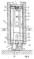
- Fig. 2 shows a schematic cross-section through an embodiment of the module 3 according to the invention, wherein the region of the module 3 for receiving the sliding door 11 is shown shortened.
- a guide rail 71 (running / sliding rail) is guided in the cutout 731, which, for example, in the illustration Fig. 2 a commercial finished product with two C-profiles is.
- the floor comprises three instead of two layers, namely, a bottom floor layer 22 (e.g., concrete floor), a middle floor layer 24 (e.g., screed), and an upper floor layer 26 (e.g., parquet).
- a bottom floor layer 22 e.g., concrete floor
- a middle floor layer 24 e.g., screed
- an upper floor layer 26 e.g., parquet
- the adjusting device 30 comprises a lower support base 32 for supporting the module 3 on the floor, in particular as shown here, for supporting on the lower floor layer 22.
- the illustrated adjusting device 30 also includes an adjusting element 34 for adjusting the height of the module 3.
- the adjusting element 34 may be, for example, a rotary plate which is rotated about transverse member 36 up or down.
- a bore 551 is formed, through which the cross member 36 acts.
- the adjustment device 30 may take any other configuration that serves to move the module 3 up and down.
- At least two support elements 38 are attached to the underside of the bottom wall 55.
- the support members 38 should be mounted by the skilled in the installation of the box 5, so that the box 5 is positionally stable and stable on the floor.
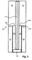
- Fig. 3 shows a schematic view from bottom to top of an embodiment of a guide device 7 for an embodiment of the module 3 according to the invention.
- the wall part 73 is arranged in a form-fitting manner around or over the guide rail 71 in one plane.
- a stop bar 735 (Avemdoppelungsmann) is arranged on both sides of the guide rail 71, which is shaped or configured so that stops 733 are formed for the side walls 51, 53.
- the guide rail 71 can abut against the rear wall 59, which is arranged below the wall portion 73 in this view.
- the wall part 73 and / or the stop strip 735 may be multi-part, for example divided according to the cut edges 734 for forming the stops 733.
- Fig. 4A shows a side view of a ready to install module 3, in which a side wall of the module 3 is removed.
- the side wall 51 is removed and the side wall 53 is visible.
- Fig. 4B shows a view of the module 3 of the in Fig. 4A B direction of view.
- Fig. 4C shows a view of the module 3 of the in Fig. 4A C direction of view.
- Fig. 5 shows a perspective view of the module 3, wherein a side wall 51 is removed.
- At least one expansion element 40 spacers
- Fig. 6 shows a schematic plan view of an embodiment of the module 3 according to the invention with a variant of a connection to a wall portion 60.
- the box 5 according to the illustrated embodiment comprises a supply channel 504 or an installation shaft for supply lines (not shown).
- the supply channel 504 is separated by a partition wall 505 from the free space 57 for receiving the sliding door 11, so that the supply lines are securely stored against damage in the supply channel 504.
- the side walls 51, 53 extend along the free space 57 for the sliding door 11, laterally from the supply channel 504 and terminate at the wall portion 60, which may for example be part of a solid wall of stone or concrete, as opposed to the outer walls 20 (see Fig. 2 ), which may be, for example, drywall or plasterboard walls.
- the wall elements 20, 60 may be of other types that are suitable for building and door assembly.
- the individual wall elements 51 with 505, 53 with 505, 51 with 59 and 53 with 59 can be fastened or connected by means of fastening elements 70.
- a bar 591 may be provided, which is arranged between the rear wall 59 of the box 5, the side walls 51, 53 and the wall portion 60.
- the strip 591 can be fastened to the wall section 60, for example with at least one dowel as a fastening element 70.
- the side walls 51, 53 may, for example, with screws as fasteners 70 are attached to the bar 591.
- the fasteners 70 may be of another type that are suitable for attachment of the described wall elements and ledge 591.
- the bar 591 is fixed to the wall portion 60, then the module 3 is constructed above or around the bar 591, and finally the side walls 51, 53 are connected to the bar 591.
- the terms “up” and “down” can be so interchanged with the respective elements that the guide means 7 is attached to the lower end 502 of the box 5 and instead of the bottom wall 55 a ceiling wall (not shown in figures) is provided so that the side walls 51, 53 and the ceiling wall each form a conclusion of the box 5.
- a wall part 73 around at least one guide rail 71 of the guide device 7 would form a lower end of the box 5 in this case.
Landscapes
- Engineering & Computer Science (AREA)
- Civil Engineering (AREA)
- Structural Engineering (AREA)
- Wing Frames And Configurations (AREA)
Claims (15)
- Module (3) de réception d'une porte coulissante (11),
le module de réception de la porte coulissante (11) comprenant un caisson sans cadre (5) qui présente une extrémité supérieure (501) et une extrémité inférieure (502), qui comprend deux parois latérales (51, 53) opposées entre lesquelles un espace libre (57) est formé pour recevoir la porte coulissante (11), et comprend une paroi de fond (55),
les parois latérales (51, 53) et la paroi de fond (55) formant respectivement une extrémité du caisson (5) et a formé une ouverte (503) de réception de la porte coulissante (11) dans le caisson (5)
et
le module de réception de la porte coulissante (11) comprenant également un dispositif de guidage (7) pour la porte coulissante (11), le dispositif de guidage (7) étant placé sur l'extrémité supérieure (501) du caisson (5) et formant une extrémité supérieure du caisson (5)
caractérisé en cela que
le caisson sans cadre est une première pièce préfabriquée (5) et le dispositif de guidage est une seconde pièce préfabriquée (7) et la première et la deuxième pièces préfabriquées sont deux pièces préfabriquées connectables. - Module (3) selon la revendication 1 comprenant en plus du caisson (5) une paroi arrière (59) qui est située en face de l'ouverture (503) du caisson (5) et formant une extrémité du caisson (5).
- Module (3) selon l'une des revendications précédentes qui comprend en plus du dispositif de guidage (7)
au moins un rail de guidage (71)
une partie de paroi (73) qui est située autour d'au moins un rail de guidage (71) sur un niveau, une excavation (731) qui est formée par le rail de guidage (71) de sorte à ce que les charnières (733) pour les parois latérales (51, 53) et une extrémité supérieure du caisson (5) se forme. - Module (3) selon l'une des revendications précédentes, les parois latérales (51, 53), la paroi de fond (55) et la paroi arrière (59) et/ou la partie de paroi (73) étant faite d'un matériau qui est composé essentiel de composantes de bois.
- Module (3) selon l'une des revendications précédentes, un profil métallique étant placé autour des parois latérales (51, 53), de la paroi de fond (55), de la paroi arrière (59) et/ou la partie de paroi (73) à fleur.
- Module (3) selon l'une des revendications précédentes, de plus avec au moins un élément d'écartement (40) qui est situé dans l'espace libre (57) du caisson (5), par exemple sous une couche supérieure du sol (26) et en dehors d'un espace coulissant (SR) de la porte coulissante (11).
- Module (3) selon l'une des revendications précédentes, de plus avec un dispositif d'ajustement (30) pour ajuster la hauteur du module (3), le dispositif d'ajustement (30) interagissant avec la paroi de fond (55) de telle sorte à ce que le module (3) puisse être déplacé vers le haut et le bas dans une direction (R30) en travers de la paroi de fond (55).
- Module (3) selon la revendication 7, le dispositif d'ajustement (30) comprenant un socle d'appui inférieur (32) et un élément de réglage (34) pour ajuster la hauteur du module (3).
- Module (3) selon la revendication 8, de plus avec au moins deux éléments d'appui (38) qui sont placés sur une partie inférieure de la paroi de fond (55).
- Module (3) selon l'une des revendications précédentes, le caisson (5) comprenant un canal d'approvisionnement (504) pour les conduites d'approvisionnement, le canal d'approvisionnement (504) étant séparé de l'espace libre (57) pour la réception de la porte coulissante (11).
- Dispositif de porte coulissante (1) avec une porte coulissante (11) et un module (3) de réception de la porte coulissante (11) selon l'une des revendications précédentes.
- Procédé de montage d'un dispositif de porte coulissante (1) pour une porte coulissante (11)
caractérisé par les étapes:Mise à disposition de deux pièces préfabriquées connectables en un module (3) de réception d'une porte coulissante (11), une première pièce préfabriquée étant formé comme un caisson (5) et une seconde pièce préfabriquée comme un dispositif de guidage (7);connexion des deux pièces préfabriquées pour former le module (3), le dispositif de guidage (7) étant fixé sur le caisson (5); etFixation finale d'une paroi arrière (59) du caisson (5) du module (5) connecté à partir des deux pièces préfabriquées sur une section de paroi (60) de sorte à ce qu'un sens de passage (R7) d'un dispositif de guidage (7) du module (3) soit orienté sur un sens coulissant (R11) de la porte coulissant (11), un passage (12) surplombe le dispositif de porte coulissante (1) et une ouverture (503) dans le caisson (5) de réception de la porte coulissante (11) soit orienté en direction du passage (12). - Procédé selon la revendication 12, le module (3) étant monté entre des parois extérieures (20), par exemple des murs en placoplâtre, ou le module (3) étant paré avec des parois extérieures (20) si bien que le module (3) forme une unité séparée des parois extérieures (20) et fermée.
- Procédé (3) selon l'une des revendications 12 à 13, un dispositif d'ajustement (30) pour ajuster la hauteur du module (3) interagissant avec une paroi de fond (55) du caisson (5) de sorte à ce que le module (3) soit déplacé pour l'ajustement vers le haut et le bas le long d'une direction (R30) transversale à la paroi de fond (55),à partir d'une couche inférieure du sol (22), par exemple un sol en béton brut, le couche inférieure de sol ayant déjà été posée, cependant pas encore une couche intermédiaire de sol à poser par dessus, par exemple une chape, et/ou pas encore non plus la couche supérieure du sol, par exemple du parquet.
- Procédé selon l'une des revendications 12 à 14, le somme d'une largeur d'une paroi extérieure (20) et d'une largeur d'une paroi latérale (51, 53) étant égale à la longueur d'une vis ou d'un clou pour le montage ou le parement si bien que les vis ou les clous ne pénètrent pas même après le montage ou le parement dans l'espace libre (57) du module (3), notamment par exemple pas en cas d'utilisation de vis à construction rapide avec une longueur classique comme par exemple 30 mm.
Applications Claiming Priority (1)
| Application Number | Priority Date | Filing Date | Title |
|---|---|---|---|
| DE102011001726.7A DE102011001726B4 (de) | 2011-04-01 | 2011-04-01 | Modul zur Aufnahme einer Schiebetür, Schiebetürvorrichtung und Verfahren zur Montage einer Schiebetürvorrichtung |
Publications (3)
| Publication Number | Publication Date |
|---|---|
| EP2505760A2 EP2505760A2 (fr) | 2012-10-03 |
| EP2505760A3 EP2505760A3 (fr) | 2014-12-17 |
| EP2505760B1 true EP2505760B1 (fr) | 2016-10-12 |
Family
ID=45952873
Family Applications (1)
| Application Number | Title | Priority Date | Filing Date |
|---|---|---|---|
| EP12160500.0A Active EP2505760B1 (fr) | 2011-04-01 | 2012-03-21 | Module de réception d'une porte coulissante, dispositif de porte coulissante et procédé de montage d'un dispositif de porte coulissante |
Country Status (2)
| Country | Link |
|---|---|
| EP (1) | EP2505760B1 (fr) |
| DE (1) | DE102011001726B4 (fr) |
Families Citing this family (2)
| Publication number | Priority date | Publication date | Assignee | Title |
|---|---|---|---|---|
| DE102012106419A1 (de) | 2012-07-17 | 2014-01-23 | Eduard Schlecht | Modul zur aufnahme einer schiebetür, wannenförmiges bauteil für ein modul zur aufnahme einer schiebetür und verfahren zur montage eines moduls für eine schiebetür |
| DE102017100696A1 (de) | 2017-01-16 | 2018-07-19 | Bos Gmbh | Stützelement zur Abstützung einer Seitenteilzarge, Seitenteilzargen-Stützanordnung sowie Montageverfahren |
Family Cites Families (16)
| Publication number | Priority date | Publication date | Assignee | Title |
|---|---|---|---|---|
| US1221766A (en) * | 1914-08-13 | 1917-04-03 | Elmer C Pitcher | Sliding-door structure. |
| US2378666A (en) * | 1942-10-21 | 1945-06-19 | Triller Benjamin Julius | Sliding door construction |
| US2857629A (en) * | 1956-03-21 | 1958-10-28 | Albert C Walter | Frame for sliding doors |
| US4561210A (en) * | 1984-02-21 | 1985-12-31 | Kvas Peter J | Sliding door |
| US4769948A (en) * | 1984-03-12 | 1988-09-13 | Carmichael Roy W | Cavity mounted door construction |
| US5125202A (en) * | 1990-11-28 | 1992-06-30 | Kissinger Terrance G | Privacy panel for use with open office furniture systems |
| IT1277197B1 (it) * | 1995-06-28 | 1997-11-05 | Krona I S P A | Struttura muraria con porta scorrevole di semplice trasporto ed assemblaggio |
| DE29510813U1 (de) * | 1995-07-04 | 1995-09-14 | Gaigl, Willi, 85659 Forstern | Vorgefertigter Bausatz zur Aufnahme einer Schiebetüre |
| FR2745601B1 (fr) * | 1996-02-29 | 1998-11-13 | Richard Malie | Systeme de porte coulissante |
| US20040003556A1 (en) * | 2002-06-06 | 2004-01-08 | Zerbst Norman F. | Workspace panel system privacy door |
| EP1559862B1 (fr) * | 2004-01-28 | 2010-03-24 | Cogi S.r.l. | Dormant d'une fenêtre ou d'une porte, facile à assembler sur le chantier |
| US20050210770A1 (en) * | 2004-03-25 | 2005-09-29 | Fackler Timothy L | Pocket door assembly |
| DE102005033417B4 (de) * | 2005-07-18 | 2007-05-10 | Albert Nehlig | Schiebetür-Element |
| AU2006200002B1 (en) * | 2006-01-03 | 2006-09-21 | Gangemi, Glen | An Adjustable in-Wall Cavity Sliding Door Frame Assembly |
| DE202006018498U1 (de) * | 2006-12-05 | 2007-03-01 | Rigips Gmbh | Verkleidungselement für eine Schiebetürvorrichtung |
| US7810283B2 (en) * | 2007-05-02 | 2010-10-12 | Steven C Rapson | Exterior pocket door |
-
2011
- 2011-04-01 DE DE102011001726.7A patent/DE102011001726B4/de not_active Expired - Fee Related
-
2012
- 2012-03-21 EP EP12160500.0A patent/EP2505760B1/fr active Active
Non-Patent Citations (1)
| Title |
|---|
| None * |
Also Published As
| Publication number | Publication date |
|---|---|
| DE102011001726A1 (de) | 2012-10-04 |
| EP2505760A3 (fr) | 2014-12-17 |
| DE102011001726B4 (de) | 2016-12-08 |
| EP2505760A2 (fr) | 2012-10-03 |
Similar Documents
| Publication | Publication Date | Title |
|---|---|---|
| DE3726255C2 (de) | Trennwand | |
| EP2446096B1 (fr) | Support d`angle pour système de façade | |
| EP1840288B1 (fr) | Agencement destiné au stockage d'objets à l'aide d'éléments de construction dans un mur constitué d'éléments préfabriqués et son procédé de fixation | |
| DE3879497T2 (de) | Metallstuetze. | |
| EP1870529A1 (fr) | Mur/ensemble de coffre pour une construction de cadre | |
| DE102011001726B4 (de) | Modul zur Aufnahme einer Schiebetür, Schiebetürvorrichtung und Verfahren zur Montage einer Schiebetürvorrichtung | |
| EP2687666B1 (fr) | Module pour la réception d'une porte coulissante et procédé de montage d'un module pour une porte coulissante | |
| WO2008092699A1 (fr) | Dispositif d'inspection, en particulier élément de recouvrement d'inspection | |
| WO2009006926A1 (fr) | CONCEPT DE PANNEAU DE PAROI À 45º | |
| DE102009011974B4 (de) | Trennwand aus vorzugsweise industriell gefertigten Wandelementen mit mehrseitig freiem Montagezugriff auf den Wandhohlraum | |
| DE102008064836B3 (de) | Pfostenleiste zur Anbringung an einem vertikalen Laibungsabschnitt einer Türöffnung sowie Montageeinrichtung zur Befestigung in der Laibung einer Türöffnung | |
| DE102021129733A1 (de) | Installations-Paket, Wandtafel mit Installations-Paket, sowie Herstellverfahren hierfür | |
| AT525231B1 (de) | Raffstorekasten und Verbindungsbeschlag zur Befestigung des Raffstores | |
| DE102017118275B4 (de) | Torvorrichtung und diese enthaltende Toranordnung | |
| CH656413A5 (de) | Wandelement. | |
| DE102016113023B4 (de) | Einbaurahmenelement und Wand mit abgedeckter Leibungsfläche | |
| DE2810981C2 (de) | Vorrichtung zur Befestigung einer Zarge | |
| DE202011000117U1 (de) | Aufdopplungsprofil | |
| DE202012007784U1 (de) | Zargenkonstruktion | |
| DE3207413C2 (de) | Industriell vorgefertigtes Wandelement | |
| DE102010017545A1 (de) | Vorhängekonstruktion für Türen | |
| DE69500653T2 (de) | Fassadenstruktur für Gebaüde oder ähnliche Strukturen | |
| DE2648935A1 (de) | Aus wenigstens einer bauplatte bestehende montagewand | |
| DE20303233U1 (de) | Wandelement | |
| DE10145052A1 (de) | Satz von Innenfutterabdeckprofilen |
Legal Events
| Date | Code | Title | Description |
|---|---|---|---|
| PUAI | Public reference made under article 153(3) epc to a published international application that has entered the european phase |
Free format text: ORIGINAL CODE: 0009012 |
|
| AK | Designated contracting states |
Kind code of ref document: A2 Designated state(s): AL AT BE BG CH CY CZ DE DK EE ES FI FR GB GR HR HU IE IS IT LI LT LU LV MC MK MT NL NO PL PT RO RS SE SI SK SM TR |
|
| AX | Request for extension of the european patent |
Extension state: BA ME |
|
| PUAL | Search report despatched |
Free format text: ORIGINAL CODE: 0009013 |
|
| AK | Designated contracting states |
Kind code of ref document: A3 Designated state(s): AL AT BE BG CH CY CZ DE DK EE ES FI FR GB GR HR HU IE IS IT LI LT LU LV MC MK MT NL NO PL PT RO RS SE SI SK SM TR |
|
| AX | Request for extension of the european patent |
Extension state: BA ME |
|
| RIC1 | Information provided on ipc code assigned before grant |
Ipc: E06B 3/46 20060101AFI20141107BHEP |
|
| 17P | Request for examination filed |
Effective date: 20150603 |
|
| RBV | Designated contracting states (corrected) |
Designated state(s): AL AT BE BG CH CY CZ DE DK EE ES FI FR GB GR HR HU IE IS IT LI LT LU LV MC MK MT NL NO PL PT RO RS SE SI SK SM TR |
|
| GRAP | Despatch of communication of intention to grant a patent |
Free format text: ORIGINAL CODE: EPIDOSNIGR1 |
|
| INTG | Intention to grant announced |
Effective date: 20160413 |
|
| GRAJ | Information related to disapproval of communication of intention to grant by the applicant or resumption of examination proceedings by the epo deleted |
Free format text: ORIGINAL CODE: EPIDOSDIGR1 |
|
| GRAL | Information related to payment of fee for publishing/printing deleted |
Free format text: ORIGINAL CODE: EPIDOSDIGR3 |
|
| GRAS | Grant fee paid |
Free format text: ORIGINAL CODE: EPIDOSNIGR3 |
|
| GRAR | Information related to intention to grant a patent recorded |
Free format text: ORIGINAL CODE: EPIDOSNIGR71 |
|
| GRAA | (expected) grant |
Free format text: ORIGINAL CODE: 0009210 |
|
| INTC | Intention to grant announced (deleted) | ||
| AK | Designated contracting states |
Kind code of ref document: B1 Designated state(s): AL AT BE BG CH CY CZ DE DK EE ES FI FR GB GR HR HU IE IS IT LI LT LU LV MC MK MT NL NO PL PT RO RS SE SI SK SM TR |
|
| INTG | Intention to grant announced |
Effective date: 20160906 |
|
| REG | Reference to a national code |
Ref country code: GB Ref legal event code: FG4D Free format text: NOT ENGLISH |
|
| REG | Reference to a national code |
Ref country code: CH Ref legal event code: EP |
|
| REG | Reference to a national code |
Ref country code: AT Ref legal event code: REF Ref document number: 836686 Country of ref document: AT Kind code of ref document: T Effective date: 20161015 |
|
| REG | Reference to a national code |
Ref country code: IE Ref legal event code: FG4D Free format text: LANGUAGE OF EP DOCUMENT: GERMAN |
|
| REG | Reference to a national code |
Ref country code: DE Ref legal event code: R096 Ref document number: 502012008464 Country of ref document: DE |
|
| REG | Reference to a national code |
Ref country code: NL Ref legal event code: FP |
|
| REG | Reference to a national code |
Ref country code: LT Ref legal event code: MG4D |
|
| PG25 | Lapsed in a contracting state [announced via postgrant information from national office to epo] |
Ref country code: LV Free format text: LAPSE BECAUSE OF FAILURE TO SUBMIT A TRANSLATION OF THE DESCRIPTION OR TO PAY THE FEE WITHIN THE PRESCRIBED TIME-LIMIT Effective date: 20161012 |
|
| REG | Reference to a national code |
Ref country code: FR Ref legal event code: PLFP Year of fee payment: 6 |
|
| PG25 | Lapsed in a contracting state [announced via postgrant information from national office to epo] |
Ref country code: NO Free format text: LAPSE BECAUSE OF FAILURE TO SUBMIT A TRANSLATION OF THE DESCRIPTION OR TO PAY THE FEE WITHIN THE PRESCRIBED TIME-LIMIT Effective date: 20170112 Ref country code: SE Free format text: LAPSE BECAUSE OF FAILURE TO SUBMIT A TRANSLATION OF THE DESCRIPTION OR TO PAY THE FEE WITHIN THE PRESCRIBED TIME-LIMIT Effective date: 20161012 Ref country code: LT Free format text: LAPSE BECAUSE OF FAILURE TO SUBMIT A TRANSLATION OF THE DESCRIPTION OR TO PAY THE FEE WITHIN THE PRESCRIBED TIME-LIMIT Effective date: 20161012 Ref country code: GR Free format text: LAPSE BECAUSE OF FAILURE TO SUBMIT A TRANSLATION OF THE DESCRIPTION OR TO PAY THE FEE WITHIN THE PRESCRIBED TIME-LIMIT Effective date: 20170113 |
|
| PG25 | Lapsed in a contracting state [announced via postgrant information from national office to epo] |
Ref country code: HR Free format text: LAPSE BECAUSE OF FAILURE TO SUBMIT A TRANSLATION OF THE DESCRIPTION OR TO PAY THE FEE WITHIN THE PRESCRIBED TIME-LIMIT Effective date: 20161012 Ref country code: PL Free format text: LAPSE BECAUSE OF FAILURE TO SUBMIT A TRANSLATION OF THE DESCRIPTION OR TO PAY THE FEE WITHIN THE PRESCRIBED TIME-LIMIT Effective date: 20161012 Ref country code: IS Free format text: LAPSE BECAUSE OF FAILURE TO SUBMIT A TRANSLATION OF THE DESCRIPTION OR TO PAY THE FEE WITHIN THE PRESCRIBED TIME-LIMIT Effective date: 20170212 Ref country code: FI Free format text: LAPSE BECAUSE OF FAILURE TO SUBMIT A TRANSLATION OF THE DESCRIPTION OR TO PAY THE FEE WITHIN THE PRESCRIBED TIME-LIMIT Effective date: 20161012 Ref country code: RS Free format text: LAPSE BECAUSE OF FAILURE TO SUBMIT A TRANSLATION OF THE DESCRIPTION OR TO PAY THE FEE WITHIN THE PRESCRIBED TIME-LIMIT Effective date: 20161012 Ref country code: PT Free format text: LAPSE BECAUSE OF FAILURE TO SUBMIT A TRANSLATION OF THE DESCRIPTION OR TO PAY THE FEE WITHIN THE PRESCRIBED TIME-LIMIT Effective date: 20170213 Ref country code: ES Free format text: LAPSE BECAUSE OF FAILURE TO SUBMIT A TRANSLATION OF THE DESCRIPTION OR TO PAY THE FEE WITHIN THE PRESCRIBED TIME-LIMIT Effective date: 20161012 |
|
| REG | Reference to a national code |
Ref country code: DE Ref legal event code: R097 Ref document number: 502012008464 Country of ref document: DE |
|
| PG25 | Lapsed in a contracting state [announced via postgrant information from national office to epo] |
Ref country code: EE Free format text: LAPSE BECAUSE OF FAILURE TO SUBMIT A TRANSLATION OF THE DESCRIPTION OR TO PAY THE FEE WITHIN THE PRESCRIBED TIME-LIMIT Effective date: 20161012 Ref country code: DK Free format text: LAPSE BECAUSE OF FAILURE TO SUBMIT A TRANSLATION OF THE DESCRIPTION OR TO PAY THE FEE WITHIN THE PRESCRIBED TIME-LIMIT Effective date: 20161012 Ref country code: RO Free format text: LAPSE BECAUSE OF FAILURE TO SUBMIT A TRANSLATION OF THE DESCRIPTION OR TO PAY THE FEE WITHIN THE PRESCRIBED TIME-LIMIT Effective date: 20161012 Ref country code: CZ Free format text: LAPSE BECAUSE OF FAILURE TO SUBMIT A TRANSLATION OF THE DESCRIPTION OR TO PAY THE FEE WITHIN THE PRESCRIBED TIME-LIMIT Effective date: 20161012 Ref country code: SK Free format text: LAPSE BECAUSE OF FAILURE TO SUBMIT A TRANSLATION OF THE DESCRIPTION OR TO PAY THE FEE WITHIN THE PRESCRIBED TIME-LIMIT Effective date: 20161012 |
|
| PLBE | No opposition filed within time limit |
Free format text: ORIGINAL CODE: 0009261 |
|
| STAA | Information on the status of an ep patent application or granted ep patent |
Free format text: STATUS: NO OPPOSITION FILED WITHIN TIME LIMIT |
|
| PG25 | Lapsed in a contracting state [announced via postgrant information from national office to epo] |
Ref country code: SM Free format text: LAPSE BECAUSE OF FAILURE TO SUBMIT A TRANSLATION OF THE DESCRIPTION OR TO PAY THE FEE WITHIN THE PRESCRIBED TIME-LIMIT Effective date: 20161012 Ref country code: BG Free format text: LAPSE BECAUSE OF FAILURE TO SUBMIT A TRANSLATION OF THE DESCRIPTION OR TO PAY THE FEE WITHIN THE PRESCRIBED TIME-LIMIT Effective date: 20170112 |
|
| 26N | No opposition filed |
Effective date: 20170713 |
|
| GBPC | Gb: european patent ceased through non-payment of renewal fee |
Effective date: 20170321 |
|
| PG25 | Lapsed in a contracting state [announced via postgrant information from national office to epo] |
Ref country code: SI Free format text: LAPSE BECAUSE OF FAILURE TO SUBMIT A TRANSLATION OF THE DESCRIPTION OR TO PAY THE FEE WITHIN THE PRESCRIBED TIME-LIMIT Effective date: 20161012 Ref country code: MC Free format text: LAPSE BECAUSE OF FAILURE TO SUBMIT A TRANSLATION OF THE DESCRIPTION OR TO PAY THE FEE WITHIN THE PRESCRIBED TIME-LIMIT Effective date: 20161012 |
|
| REG | Reference to a national code |
Ref country code: IE Ref legal event code: MM4A |
|
| PG25 | Lapsed in a contracting state [announced via postgrant information from national office to epo] |
Ref country code: GB Free format text: LAPSE BECAUSE OF NON-PAYMENT OF DUE FEES Effective date: 20170321 Ref country code: IE Free format text: LAPSE BECAUSE OF NON-PAYMENT OF DUE FEES Effective date: 20170321 |
|
| REG | Reference to a national code |
Ref country code: FR Ref legal event code: PLFP Year of fee payment: 7 |
|
| PG25 | Lapsed in a contracting state [announced via postgrant information from national office to epo] |
Ref country code: MT Free format text: LAPSE BECAUSE OF FAILURE TO SUBMIT A TRANSLATION OF THE DESCRIPTION OR TO PAY THE FEE WITHIN THE PRESCRIBED TIME-LIMIT Effective date: 20161012 |
|
| PG25 | Lapsed in a contracting state [announced via postgrant information from national office to epo] |
Ref country code: HU Free format text: LAPSE BECAUSE OF FAILURE TO SUBMIT A TRANSLATION OF THE DESCRIPTION OR TO PAY THE FEE WITHIN THE PRESCRIBED TIME-LIMIT; INVALID AB INITIO Effective date: 20120321 |
|
| PG25 | Lapsed in a contracting state [announced via postgrant information from national office to epo] |
Ref country code: CY Free format text: LAPSE BECAUSE OF NON-PAYMENT OF DUE FEES Effective date: 20161012 |
|
| PG25 | Lapsed in a contracting state [announced via postgrant information from national office to epo] |
Ref country code: MK Free format text: LAPSE BECAUSE OF FAILURE TO SUBMIT A TRANSLATION OF THE DESCRIPTION OR TO PAY THE FEE WITHIN THE PRESCRIBED TIME-LIMIT Effective date: 20161012 |
|
| PG25 | Lapsed in a contracting state [announced via postgrant information from national office to epo] |
Ref country code: TR Free format text: LAPSE BECAUSE OF FAILURE TO SUBMIT A TRANSLATION OF THE DESCRIPTION OR TO PAY THE FEE WITHIN THE PRESCRIBED TIME-LIMIT Effective date: 20161012 |
|
| PG25 | Lapsed in a contracting state [announced via postgrant information from national office to epo] |
Ref country code: AL Free format text: LAPSE BECAUSE OF FAILURE TO SUBMIT A TRANSLATION OF THE DESCRIPTION OR TO PAY THE FEE WITHIN THE PRESCRIBED TIME-LIMIT Effective date: 20161012 |
|
| PGFP | Annual fee paid to national office [announced via postgrant information from national office to epo] |
Ref country code: IT Payment date: 20250325 Year of fee payment: 14 |
|
| PGFP | Annual fee paid to national office [announced via postgrant information from national office to epo] |
Ref country code: DE Payment date: 20250523 Year of fee payment: 14 |
|
| PGFP | Annual fee paid to national office [announced via postgrant information from national office to epo] |
Ref country code: CH Payment date: 20250401 Year of fee payment: 14 |
|
| REG | Reference to a national code |
Ref country code: CH Ref legal event code: U11 Free format text: ST27 STATUS EVENT CODE: U-0-0-U10-U11 (AS PROVIDED BY THE NATIONAL OFFICE) Effective date: 20260410 |
|
| PGFP | Annual fee paid to national office [announced via postgrant information from national office to epo] |
Ref country code: AT Payment date: 20260331 Year of fee payment: 15 |
|
| PGFP | Annual fee paid to national office [announced via postgrant information from national office to epo] |
Ref country code: LU Payment date: 20260330 Year of fee payment: 15 Ref country code: BE Payment date: 20260330 Year of fee payment: 15 |
|
| PGFP | Annual fee paid to national office [announced via postgrant information from national office to epo] |
Ref country code: NL Payment date: 20260330 Year of fee payment: 15 |
|
| PGFP | Annual fee paid to national office [announced via postgrant information from national office to epo] |
Ref country code: FR Payment date: 20260331 Year of fee payment: 15 |