EP2505879B1 - Getriebe mit einem Ölverteiler - Google Patents
Getriebe mit einem Ölverteiler Download PDFInfo
- Publication number
- EP2505879B1 EP2505879B1 EP12162234.4A EP12162234A EP2505879B1 EP 2505879 B1 EP2505879 B1 EP 2505879B1 EP 12162234 A EP12162234 A EP 12162234A EP 2505879 B1 EP2505879 B1 EP 2505879B1
- Authority
- EP
- European Patent Office
- Prior art keywords
- gearbox
- oil
- shaft
- oil spreader
- vanes
- Prior art date
- Legal status (The legal status is an assumption and is not a legal conclusion. Google has not performed a legal analysis and makes no representation as to the accuracy of the status listed.)
- Not-in-force
Links
- 238000005096 rolling process Methods 0.000 claims description 3
- 239000003921 oil Substances 0.000 description 45
- 230000002000 scavenging effect Effects 0.000 description 5
- 238000001816 cooling Methods 0.000 description 2
- 239000000446 fuel Substances 0.000 description 2
- 239000000314 lubricant Substances 0.000 description 2
- 238000005461 lubrication Methods 0.000 description 2
- 230000000712 assembly Effects 0.000 description 1
- 238000000429 assembly Methods 0.000 description 1
- 239000010724 circulating oil Substances 0.000 description 1
- 239000000284 extract Substances 0.000 description 1
- 230000005484 gravity Effects 0.000 description 1
- 238000009434 installation Methods 0.000 description 1
- 230000001050 lubricating effect Effects 0.000 description 1
- 238000004519 manufacturing process Methods 0.000 description 1
- 230000013011 mating Effects 0.000 description 1
- 229910001092 metal group alloy Inorganic materials 0.000 description 1
- 239000003208 petroleum Substances 0.000 description 1
- 239000007921 spray Substances 0.000 description 1
- 239000007858 starting material Substances 0.000 description 1
Images



Classifications
-
- F—MECHANICAL ENGINEERING; LIGHTING; HEATING; WEAPONS; BLASTING
- F16—ENGINEERING ELEMENTS AND UNITS; GENERAL MEASURES FOR PRODUCING AND MAINTAINING EFFECTIVE FUNCTIONING OF MACHINES OR INSTALLATIONS; THERMAL INSULATION IN GENERAL
- F16H—GEARING
- F16H57/00—General details of gearing
- F16H57/04—Features relating to lubrication or cooling or heating
- F16H57/042—Guidance of lubricant
- F16H57/0427—Guidance of lubricant on rotary parts, e.g. using baffles for collecting lubricant by centrifugal force
-
- F—MECHANICAL ENGINEERING; LIGHTING; HEATING; WEAPONS; BLASTING
- F05—INDEXING SCHEMES RELATING TO ENGINES OR PUMPS IN VARIOUS SUBCLASSES OF CLASSES F01-F04
- F05D—INDEXING SCHEME FOR ASPECTS RELATING TO NON-POSITIVE-DISPLACEMENT MACHINES OR ENGINES, GAS-TURBINES OR JET-PROPULSION PLANTS
- F05D2260/00—Function
- F05D2260/60—Fluid transfer
- F05D2260/602—Drainage
-
- F—MECHANICAL ENGINEERING; LIGHTING; HEATING; WEAPONS; BLASTING
- F16—ENGINEERING ELEMENTS AND UNITS; GENERAL MEASURES FOR PRODUCING AND MAINTAINING EFFECTIVE FUNCTIONING OF MACHINES OR INSTALLATIONS; THERMAL INSULATION IN GENERAL
- F16H—GEARING
- F16H57/00—General details of gearing
- F16H57/04—Features relating to lubrication or cooling or heating
- F16H57/0434—Features relating to lubrication or cooling or heating relating to lubrication supply, e.g. pumps; Pressure control
- F16H57/0443—Features relating to lubrication or cooling or heating relating to lubrication supply, e.g. pumps; Pressure control for supply of lubricant during tilt or high acceleration, e.g. problems related to the tilt or extreme acceleration of the transmission casing and the supply of lubricant under these conditions
-
- Y—GENERAL TAGGING OF NEW TECHNOLOGICAL DEVELOPMENTS; GENERAL TAGGING OF CROSS-SECTIONAL TECHNOLOGIES SPANNING OVER SEVERAL SECTIONS OF THE IPC; TECHNICAL SUBJECTS COVERED BY FORMER USPC CROSS-REFERENCE ART COLLECTIONS [XRACs] AND DIGESTS
- Y10—TECHNICAL SUBJECTS COVERED BY FORMER USPC
- Y10T—TECHNICAL SUBJECTS COVERED BY FORMER US CLASSIFICATION
- Y10T74/00—Machine element or mechanism
- Y10T74/19—Gearing
- Y10T74/19991—Lubrication
-
- Y—GENERAL TAGGING OF NEW TECHNOLOGICAL DEVELOPMENTS; GENERAL TAGGING OF CROSS-SECTIONAL TECHNOLOGIES SPANNING OVER SEVERAL SECTIONS OF THE IPC; TECHNICAL SUBJECTS COVERED BY FORMER USPC CROSS-REFERENCE ART COLLECTIONS [XRACs] AND DIGESTS
- Y10—TECHNICAL SUBJECTS COVERED BY FORMER USPC
- Y10T—TECHNICAL SUBJECTS COVERED BY FORMER US CLASSIFICATION
- Y10T74/00—Machine element or mechanism
- Y10T74/21—Elements
- Y10T74/2186—Gear casings
Definitions
- This invention relates generally to gearboxes and more particularly to control of oil flow in gearboxes for gas turbine engines.
- a gas turbine engine usually includes one or more mechanically-driven accessories, such as fuel or oil pumps, generators or alternators, control units, and the like. Such accessories are mounted to an accessory gearbox ("AGB”) which extracts torque from the engine, and drives each accessory at the required rotational speed, using an internal gear train.
- AGB accessory gearbox
- Pressurized oil flow is delivered to the AGB for lubrication and cooling.
- the spent oil from the AGB drains back to a supply and scavenging system of the engine. Because such engines are often used in aircraft, the engine's orientation (i.e. its roll and pitch angle) varies significantly during operation.
- Some engine orientations can cause an excessive amount of oil draining from the AGB to flow into a bearing sump of the engine, instead of directly to an oil tank.
- This excessive oil inflow can exceed the capability of the supply and scavenge system to remove or scavenge oil from the sump.
- This in turn can cause churning or flooding of oil in the sump, which in turn can cause engine stalls.
- US 4,964,489 relates to a jet spray slinger for lubricating moving parts within a housing, and discloses features generally corresponding to the preamble of claim 1 herein.
- the invention provides a gearbox in accordance with claim 1 herein.
- FIG. 1 depicts an aircraft gas turbine engine 10.
- the illustrated example is a turboshaft engine, but the principles of the present invention are applicable to any type of gearbox having a circulating oil supply.
- the engine 10 has an accessory gearbox ("AGB") 12 mounted to it.
- AGB 12 accessory gearbox
- Various shaft-driven engine accessories (shown generally at 14), such as oil and fuel pumps, starters, generators, alternators, etc. are mounted to the AGB 12.
- Torque from the engine 10 is transferred through a gear train housed within the AGB 12 to drive each of the individual accessories 14.
- FIG. 2 is a partially cut-away view of the AGB 12.
- the AGB 12 has a stationary housing 16.
- a shaft 18, also referred to as an "A-axis shaft”, is mounted in the housing 16 and extends along a radial axis (labeled "A") that intersects the longitudinal centerline axis of the engine 10.
- the shaft 18 has an inner end 20 and an outer end 22.
- the inner end 20 is engaged with a drive gear (not shown) of the engine 10.
- the outer end 22 carries a bevel gear 24 which engages another bevel gear 26.
- the bevel gear 26 is engaged with other gears (not shown) within the housing 16.
- the gears are configured in a known manner to drive multiple output shafts at the speeds and directions needed for the various accessories 14 (shown in FIG. 1 ).
- FIGS. 4 and 5 show in more detail how the shaft 18 is mounted. Specifically, the shaft 18 rotates in an upper bearing assembly 28 and a lower bearing assembly 30. It is noted that, as used herein, directional terms applied to certain components (for example, “upper”, “lower”, “inner”, and “outer”) are intended for the purpose of convenient reference and description, and do not imply that any particular orientation of the component is necessary relative to the external environment.
- the upper bearing assembly 28 comprises an outer race 32 received in an upper bore 34 of the housing 16, an inner race 36 fixedly attached to the shaft 18 (for example by interference fit), and a plurality of rolling elements 38 such as balls or rollers disposed between the inner and outer races 36 and 32.
- fixedly means that the two components which are “fixedly attached” to each other do not experience relative movement to each other during normal operation of the AGB 12.
- the diameter of the upper bore 34 is selected to be greater than the maximum diameter of the bevel gear 24.
- the lower bearing assembly 30 (best seen in FIG. 5 ) comprises an annular outer race 40 fixedly mounted to a lower bore 42 in the housing 16 (for example by interference fit), an annular inner race 44 fixedly mounted to the shaft 18 (for example by interference fit), and a plurality of rolling elements 46 such as balls or rollers disposed between the inner and outer races 44 and 40.
- the interior of the housing 16, including the upper and lower bearing assemblies 28 and 30, is provided with a flow of lubricant such as petroleum-based oil for cooling and lubrication.
- the lubricant flow is provided by a supply and scavenging system of a known type, which is not shown.
- the spent oil drains vertically downward by gravity.
- Some of the oil drain flow (shown by arrow "D1") passes along a first internal flow path which leads to an oil tank 48 (shown schematically in FIG. 2 ).
- the remainder of the oil drain flow (shown by arrow "D2”) runs along a second internal flow path, down the exterior of the shaft 18, and eventually into a bearing sump 50 of the engine (shown schematically in FIG. 2 ).
- FIG. 2 corresponds to conditions during level-flight operation of the engine.
- an arrow "G” representing a vertical or 12:00 o'clock direction of the AGB 12 coincides with an earth-vertical vector "V” shown.
- the proportion of the oil drain flow passing into the bearing sump 50 is within the design capacity of the supply and scavenging system to remove excess oil from the bearing sump 50.
- FIG. 3 corresponds to operation of the engine 10 and AGB 12 in a position rolled away from the vertical orientation.
- an arrow "G" representing a vertical or 12:00 o'clock direction of the AGB 12 defines a nonzero angle ⁇ with an earth-vertical vector V.
- a greater proportion of the oil drain flow D2 passes down along the shaft 18 and into the bearing sump 50 than when then engine 10 is in a vertical orientation. Under some circumstances this flow can exceed the scavenging ability of the bearing sump 50, leading to oil churning and/or flooding, and possibly causing engine stalls.
- the AGB is provided with an oil spreader 52 (seen in FIG. 5 ) which is attached to the shaft 18 just below the lower bearing assembly 30.
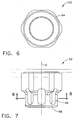
- FIGS. 6-9 illustrate the oil spreader 52 in more detail.
- the oil spreader has an annular body (generally in the shape of a hollow cylinder) with a central axis "C", an upper end 54, and a lower end 56. As illustrated it is a single integral component made from a metal alloy, but it could be built up from smaller components. It is roughly divided into an upper portion 58 and a lower portion 60.
- the interior of the upper portion 58 is provided with female threads 62, and the exterior may be formed into wrenching flats 64, i.e. planar surfaces arranged in a hexagon or other shape to facilitate installation and removal of the oil spreader 52 using a wrench, spanner, or other similar tool.
- the maximum outer diameter of the oil spreader 52 is less than the inside diameter of the outer race 40 of the lower bearing assembly 30.
- An annular array of circumferentially spaced-apart vanes 66 extend in a generally axial direction between the upper portion 58 and a ring 68 located at the lower end 56.
- the ring 68 interconnects the distal ends of the vanes 66.
- Open slots 70 are defined between the sidewalls 72 of each pair of adjacent vanes 66.
- the vanes 66 are configured so as to function as a centrifugal pump and effectively create a radially outward air flow when the oil spreader 52 rotates about its central axis C.
- each of the vanes 66 is defined in part by two sidewalls 72 oriented at an oblique angle to each other, creating a wedge-shaped in cross-section.
- the sidewalls 72 of adjacent vanes 66 are aligned parallel to a radial direction, denoted "r" in FIG. 8 .
- the vanes 66 may have a different cross-sectional shape or may be turned at a different angle relative to the radial direction r in order to provide an effective air flow.
- the number and size of the vanes 66 may also be varied to suit a particular application.
- the oil spreader 52 is shown installed in FIG. 5 .
- the female threads 62 engage mating male threads 74 of the shaft 18, and the oil spreader 52 is screwed into position abutting the inner race 44 of the lower bearing assembly 30.
- the oil spreader 52 may be installed without disassembling or removing the AGB 12 from the engine 10.
- a cover 76 (seen in FIG. 4 ) is removed and the shaft 18 is withdrawn from the AGB 12.
- the oil spreader 52 is then threaded onto the shaft 18.
- the shaft 18 is then reinserted. Because the outer diameter of the oil spreader 52 is less than the inside diameter of the outer race 40, it is able to pass therethrough without interference. Finally the cover 76 is replaced.
- the rotating oil spreader 52 In operation, the rotating oil spreader 52 generates a radially outward flow of air, in the manner of a centrifugal pump. This flow of air (shown schematically by the block arrows in FIG. 5 ) entrains oil and directs it away from the shaft 18 and the flowpath to the bearing sump 50, and towards the oil tank 48 (seen in FIG. 3 ). This ensures that the flow rate of oil into the bearing sump 50 is not excessive regardless of the orientation of the AGB 12.
- the oil spreader described herein has several advantages as compared to prior art configurations. It can be both a production component and a field retrofit. It is inexpensive and in the case of a field retrofit, it does not require removal of the AGB 12, as the shaft 18 can be removed and reinstalled while the AGB 12 remains installed on the engine 10. This represents a significant savings in time, effort, and cost compared to other means for controlling oil flow.
Landscapes
- Engineering & Computer Science (AREA)
- General Engineering & Computer Science (AREA)
- Mechanical Engineering (AREA)
- General Details Of Gearings (AREA)
Claims (9)
- Getriebekasten (12), der umfasst:ein Gehäuse (16), das mindestens ein Getriebe einhaust;einen Schaft (18), der rotierbar im Gehäuse (16) angebracht ist, wobei der Schaft (18) eine Mittelachse (A) und obere und untere Enden (22, 20) aufweist; undeinen Ölverteiler (52), der an einem Bereich des Schafts (18) befestigt ist und diesen Bereich umgibt, wobei der Ölverteiler (52) einen ringförmigen Körper mit einer Mittelachse (C), sich gegenüberliegenden oberen und unteren Enden (54, 56), einem oberen Abschnitt (58), der an dem oberen Ende des ringförmigen Körpers angrenzt, und einen unteren Bereich (60), der an einem unteren Ende des ringförmigen Körpers angrenzt, aufweist, wobei der untere Bereich (60) mindestens zwei Schaufeln (66) aufweist, die sich zwischen dem oberen Abschnitt (58) und einem ringförmigen Ring (68), der an dem unteren Ende des ringförmigen Körpers angeordnet ist, erstrecken, wobei die Schaufeln (66) zwischen einander Aussparungen (70) bilden;dadurch gekennzeichnet, dass:der Schaft (18) mittels einer unteren Lagerbaugruppe (30) und einer oberen Lagerbaugruppe (28) an dem Getriebekasten (12) angeordnet ist, und der Ölverteiler (52) angrenzend an die untere Lagerbaugruppe angeordnet ist;wobei die untere Lagerbaugruppe (30) umfasst:einen ringförmigen Außenring (40), der starr an einer unteren Bohrung (42) in dem Gehäuse (16) angebracht ist;einen ringförmigen Innenring (44), der starr an dem Schaft (18) angebracht ist; undeine Vielzahl von Wälzkörpern (46), die zwischen dem Innenring und dem Außenring angeordnet sind;wobei ein größter Außendurchmesser des Ölverteilers (52) so dimensioniert ist, dass er durch einen Innendurchmesser des Außenrings (40) ohne Beeinträchtigung hindurchpasst.
- Getriebekasten (12) gemäß Anspruch 1, bei dem der untere Abschnitt (60) des Ölverteilers (52) eine ringförmige Anordnung von acht gleichmäßig voneinander beabstandeten Schaufeln (66) aufweist, die sich zwischen dem oberen Bereich (58) und dem ringförmigen Ring (68) erstrecken, wobei eine offene Aussparung zwischen Seitenwänden (72) von jedem Paar zueinander benachbarter Schaufeln (66) gebildet ist.
- Getriebekasten (12) gemäß Anspruch 1 oder 2, bei dem der Ölverteiler (52) an dem Schaft (18) mittels einer Gewindeverbindung (62) angebracht ist.
- Getriebekasten (12) gemäß einem der Ansprüche 1 bis 3, bei dem eine äußere Oberfläche des oberen Abschnitts (58) des Ölverteilers (52) eine Vielzahl von Schraubflächen (64) definiert.
- Getriebekasten (12) gemäß einem der Ansprüche 1 bis 4, bei dem jede der Schaufeln (66) des Ölverteilers (52) teilweise durch ein Paar von voneinander beabstandeten Seitenwänden (72) definiert ist, die in einem schrägen Winkel zueinander angeordnet sind.
- Getriebekasten (12) gemäß Anspruch 5, bei dem die Seitenwände (72) parallel zu einer Richtung radial zur Mittelachse (C) des Ölverteilers angeordnet sind.
- Getriebekasten (12) gemäß Anspruch 1, bei dem der untere Abschnitt (60) eine Anordnung von Schaufeln (66) umfasst, die sich zwischen dem oberen Abschnitt (58) und dem ringförmigen Ring (68) erstrecken.
- Getriebekasten (12) gemäß Anspruch 1 oder 7, der außerdem weibliche Gewinde (62) aufweist, die an einer inneren Oberfläche des oberen Abschnitts (58) gebildet sind.
- Getriebekasten (12) gemäß Anspruch 7 oder 8, bei dem eine äußere Oberfläche des oberen Abschnitts (58) eine Vielzahl von Schraubflächen (64) definiert.
Applications Claiming Priority (1)
| Application Number | Priority Date | Filing Date | Title |
|---|---|---|---|
| US13/077,205 US20120247250A1 (en) | 2011-03-31 | 2011-03-31 | Gearbox and oil spreader thereof |
Publications (2)
| Publication Number | Publication Date |
|---|---|
| EP2505879A1 EP2505879A1 (de) | 2012-10-03 |
| EP2505879B1 true EP2505879B1 (de) | 2014-05-14 |
Family
ID=45952935
Family Applications (1)
| Application Number | Title | Priority Date | Filing Date |
|---|---|---|---|
| EP12162234.4A Not-in-force EP2505879B1 (de) | 2011-03-31 | 2012-03-29 | Getriebe mit einem Ölverteiler |
Country Status (4)
| Country | Link |
|---|---|
| US (1) | US20120247250A1 (de) |
| EP (1) | EP2505879B1 (de) |
| JP (1) | JP2012215296A (de) |
| CA (1) | CA2772161A1 (de) |
Families Citing this family (6)
| Publication number | Priority date | Publication date | Assignee | Title |
|---|---|---|---|---|
| DE102010061896A1 (de) * | 2010-11-24 | 2012-05-24 | Dr. Ing. H.C. F. Porsche Aktiengesellschaft | Anordnung einer Ölpumpe in einem Getriebe |
| US20130180262A1 (en) * | 2012-01-18 | 2013-07-18 | Hung Duong | Gas turbine engine accessory gearbox |
| US10054080B2 (en) * | 2012-10-22 | 2018-08-21 | United Technologies Corporation | Coil spring hanger for exhaust duct liner |
| FR3007458B1 (fr) * | 2013-06-21 | 2017-11-10 | Snecma | Carter intermediaire ameliore de turbomachine et ensemble d'entrainement de boitier d'accessoire |
| US11203949B2 (en) * | 2016-08-11 | 2021-12-21 | General Electric Company | Mechanically driven air vehicle thermal management device |
| CN107882962A (zh) * | 2016-09-28 | 2018-04-06 | 中车北京南口机械有限公司 | 轨道交通车辆的齿轮箱的箱体 |
Family Cites Families (13)
| Publication number | Priority date | Publication date | Assignee | Title |
|---|---|---|---|---|
| US2217777A (en) * | 1937-07-06 | 1940-10-15 | William H Heyser | Gas generator for oil operated orchard heaters |
| US3520632A (en) * | 1968-11-19 | 1970-07-14 | United Aircraft Corp | Scavenge pump and accessory drive system |
| US3943895A (en) * | 1974-11-29 | 1976-03-16 | Howell Roy M | Barrel type internal combustion engine |
| US4046223A (en) * | 1975-10-15 | 1977-09-06 | General Electric Company | Bearing sump cooling arrangement |
| JPS585044Y2 (ja) * | 1979-04-16 | 1983-01-28 | 日産自動車株式会社 | 内燃機関のブロ−バイガス環元装置用オイルセパレ−タ |
| US4964489A (en) * | 1987-11-05 | 1990-10-23 | Dresser Industries, Inc. | Jet spray slinger |
| US5257903A (en) * | 1991-10-30 | 1993-11-02 | General Electric Company | Low pressure drop radial inflow air-oil separating arrangement and separator employed therein |
| US6705349B2 (en) * | 2001-10-22 | 2004-03-16 | General Electric Company | Weep plug |
| US7334982B2 (en) * | 2005-05-06 | 2008-02-26 | General Electric Company | Apparatus for scavenging lubricating oil |
| DE502006007644D1 (de) * | 2005-05-10 | 2010-09-23 | Mahle Int Gmbh | In eine axial hohle welle eines verbrennungsmotors integrierte zentrifugal-ölnebelabscheidereinrichtung |
| JP4934371B2 (ja) * | 2006-08-11 | 2012-05-16 | 愛知機械工業株式会社 | 潤滑装置 |
| DE102007040474A1 (de) * | 2007-08-28 | 2009-03-05 | Schaeffler Kg | Stirnraddifferential |
| US7950876B2 (en) * | 2008-10-21 | 2011-05-31 | Suver Paul W | Socket wrench attachment for rotary drive member |
-
2011
- 2011-03-31 US US13/077,205 patent/US20120247250A1/en not_active Abandoned
-
2012
- 2012-03-22 CA CA2772161A patent/CA2772161A1/en not_active Abandoned
- 2012-03-28 JP JP2012072835A patent/JP2012215296A/ja active Pending
- 2012-03-29 EP EP12162234.4A patent/EP2505879B1/de not_active Not-in-force
Also Published As
| Publication number | Publication date |
|---|---|
| EP2505879A1 (de) | 2012-10-03 |
| CA2772161A1 (en) | 2012-09-30 |
| US20120247250A1 (en) | 2012-10-04 |
| JP2012215296A (ja) | 2012-11-08 |
Similar Documents
| Publication | Publication Date | Title |
|---|---|---|
| EP2505879B1 (de) | Getriebe mit einem Ölverteiler | |
| US9353848B2 (en) | Spline lubrication system | |
| US11053860B2 (en) | Compact accessory systems for a gas turbine engine | |
| JP4722086B2 (ja) | タービンエンジン、エピサイクリック歯車列用のキャリア、およびエピサイクリック歯車列を組み立てる方法 | |
| US9897010B2 (en) | Air turbine starter systems including gearbox-integrated clutch modules and gas turbine engines employing the same | |
| US11753998B2 (en) | Compact accessory systems for a gas turbine engine | |
| EP2157289B1 (de) | Öldichtung mit pumpenden Laufrad | |
| EP3674584B1 (de) | Flüssigkeitssammelrinne für einen getriebeturbinenmotor | |
| EP2766622B1 (de) | Dynamisch geschmiertes lager | |
| RU2666265C2 (ru) | Коробка приводов | |
| EP2107218B1 (de) | Schmier- und Rücklaufsystem | |
| EP2562437A2 (de) | Schrägkugellager | |
| EP3098480B1 (de) | Getriebeummantelung zur passiven schmierung einer getriebekomponente | |
| EP3859191B1 (de) | Flüssigkeitssammelrinne für einen getriebeturbinenmotor | |
| CA2851234C (en) | Dynamically-lubricated bearing and method of dynamically lubricating a bearing | |
| EP3222886B1 (de) | Achsenanordnung mit schmiermittelreservoir | |
| EP3001072B1 (de) | Ölübertragungslager und ölübertragungsverfahren | |
| EP2914832B1 (de) | Gasturbinenmotor mit lagergehäusewandkühlung | |
| EP3388641A1 (de) | Dichtungsanordnung für ein lagergehäuse eines gasturbinentriebwerks und mutter | |
| CN107110424B (zh) | 涡轮机设备的润滑油收集帽 | |
| CN113530687B (zh) | 用于发动机起动器中的部件的润滑系统 | |
| CN110494631A (zh) | 燃气涡轮发动机的附件继动器 | |
| JP2007315568A (ja) | ピニオン軸支持用軸受装置 | |
| US20260110267A1 (en) | Baffle assembly for interacting with lubricating fluid |
Legal Events
| Date | Code | Title | Description |
|---|---|---|---|
| PUAI | Public reference made under article 153(3) epc to a published international application that has entered the european phase |
Free format text: ORIGINAL CODE: 0009012 |
|
| AK | Designated contracting states |
Kind code of ref document: A1 Designated state(s): AL AT BE BG CH CY CZ DE DK EE ES FI FR GB GR HR HU IE IS IT LI LT LU LV MC MK MT NL NO PL PT RO RS SE SI SK SM TR |
|
| AX | Request for extension of the european patent |
Extension state: BA ME |
|
| 17P | Request for examination filed |
Effective date: 20130403 |
|
| GRAP | Despatch of communication of intention to grant a patent |
Free format text: ORIGINAL CODE: EPIDOSNIGR1 |
|
| INTG | Intention to grant announced |
Effective date: 20131115 |
|
| GRAS | Grant fee paid |
Free format text: ORIGINAL CODE: EPIDOSNIGR3 |
|
| GRAA | (expected) grant |
Free format text: ORIGINAL CODE: 0009210 |
|
| AK | Designated contracting states |
Kind code of ref document: B1 Designated state(s): AL AT BE BG CH CY CZ DE DK EE ES FI FR GB GR HR HU IE IS IT LI LT LU LV MC MK MT NL NO PL PT RO RS SE SI SK SM TR |
|
| REG | Reference to a national code |
Ref country code: GB Ref legal event code: FG4D |
|
| REG | Reference to a national code |
Ref country code: AT Ref legal event code: REF Ref document number: 668536 Country of ref document: AT Kind code of ref document: T Effective date: 20140615 |
|
| REG | Reference to a national code |
Ref country code: IE Ref legal event code: FG4D |
|
| REG | Reference to a national code |
Ref country code: DE Ref legal event code: R096 Ref document number: 602012001669 Country of ref document: DE Effective date: 20140626 |
|
| REG | Reference to a national code |
Ref country code: NL Ref legal event code: VDEP Effective date: 20140514 Ref country code: AT Ref legal event code: MK05 Ref document number: 668536 Country of ref document: AT Kind code of ref document: T Effective date: 20140514 |
|
| REG | Reference to a national code |
Ref country code: LT Ref legal event code: MG4D |
|
| PG25 | Lapsed in a contracting state [announced via postgrant information from national office to epo] |
Ref country code: IS Free format text: LAPSE BECAUSE OF FAILURE TO SUBMIT A TRANSLATION OF THE DESCRIPTION OR TO PAY THE FEE WITHIN THE PRESCRIBED TIME-LIMIT Effective date: 20140914 Ref country code: LT Free format text: LAPSE BECAUSE OF FAILURE TO SUBMIT A TRANSLATION OF THE DESCRIPTION OR TO PAY THE FEE WITHIN THE PRESCRIBED TIME-LIMIT Effective date: 20140514 Ref country code: NO Free format text: LAPSE BECAUSE OF FAILURE TO SUBMIT A TRANSLATION OF THE DESCRIPTION OR TO PAY THE FEE WITHIN THE PRESCRIBED TIME-LIMIT Effective date: 20140814 Ref country code: FI Free format text: LAPSE BECAUSE OF FAILURE TO SUBMIT A TRANSLATION OF THE DESCRIPTION OR TO PAY THE FEE WITHIN THE PRESCRIBED TIME-LIMIT Effective date: 20140514 Ref country code: GR Free format text: LAPSE BECAUSE OF FAILURE TO SUBMIT A TRANSLATION OF THE DESCRIPTION OR TO PAY THE FEE WITHIN THE PRESCRIBED TIME-LIMIT Effective date: 20140815 Ref country code: CY Free format text: LAPSE BECAUSE OF FAILURE TO SUBMIT A TRANSLATION OF THE DESCRIPTION OR TO PAY THE FEE WITHIN THE PRESCRIBED TIME-LIMIT Effective date: 20140514 |
|
| PG25 | Lapsed in a contracting state [announced via postgrant information from national office to epo] |
Ref country code: LV Free format text: LAPSE BECAUSE OF FAILURE TO SUBMIT A TRANSLATION OF THE DESCRIPTION OR TO PAY THE FEE WITHIN THE PRESCRIBED TIME-LIMIT Effective date: 20140514 Ref country code: PL Free format text: LAPSE BECAUSE OF FAILURE TO SUBMIT A TRANSLATION OF THE DESCRIPTION OR TO PAY THE FEE WITHIN THE PRESCRIBED TIME-LIMIT Effective date: 20140514 Ref country code: RS Free format text: LAPSE BECAUSE OF FAILURE TO SUBMIT A TRANSLATION OF THE DESCRIPTION OR TO PAY THE FEE WITHIN THE PRESCRIBED TIME-LIMIT Effective date: 20140514 Ref country code: HR Free format text: LAPSE BECAUSE OF FAILURE TO SUBMIT A TRANSLATION OF THE DESCRIPTION OR TO PAY THE FEE WITHIN THE PRESCRIBED TIME-LIMIT Effective date: 20140514 Ref country code: AT Free format text: LAPSE BECAUSE OF FAILURE TO SUBMIT A TRANSLATION OF THE DESCRIPTION OR TO PAY THE FEE WITHIN THE PRESCRIBED TIME-LIMIT Effective date: 20140514 Ref country code: ES Free format text: LAPSE BECAUSE OF FAILURE TO SUBMIT A TRANSLATION OF THE DESCRIPTION OR TO PAY THE FEE WITHIN THE PRESCRIBED TIME-LIMIT Effective date: 20140514 Ref country code: SE Free format text: LAPSE BECAUSE OF FAILURE TO SUBMIT A TRANSLATION OF THE DESCRIPTION OR TO PAY THE FEE WITHIN THE PRESCRIBED TIME-LIMIT Effective date: 20140514 |
|
| PG25 | Lapsed in a contracting state [announced via postgrant information from national office to epo] |
Ref country code: PT Free format text: LAPSE BECAUSE OF FAILURE TO SUBMIT A TRANSLATION OF THE DESCRIPTION OR TO PAY THE FEE WITHIN THE PRESCRIBED TIME-LIMIT Effective date: 20140915 |
|
| PG25 | Lapsed in a contracting state [announced via postgrant information from national office to epo] |
Ref country code: CZ Free format text: LAPSE BECAUSE OF FAILURE TO SUBMIT A TRANSLATION OF THE DESCRIPTION OR TO PAY THE FEE WITHIN THE PRESCRIBED TIME-LIMIT Effective date: 20140514 Ref country code: BE Free format text: LAPSE BECAUSE OF FAILURE TO SUBMIT A TRANSLATION OF THE DESCRIPTION OR TO PAY THE FEE WITHIN THE PRESCRIBED TIME-LIMIT Effective date: 20140514 Ref country code: EE Free format text: LAPSE BECAUSE OF FAILURE TO SUBMIT A TRANSLATION OF THE DESCRIPTION OR TO PAY THE FEE WITHIN THE PRESCRIBED TIME-LIMIT Effective date: 20140514 Ref country code: RO Free format text: LAPSE BECAUSE OF FAILURE TO SUBMIT A TRANSLATION OF THE DESCRIPTION OR TO PAY THE FEE WITHIN THE PRESCRIBED TIME-LIMIT Effective date: 20140514 Ref country code: SK Free format text: LAPSE BECAUSE OF FAILURE TO SUBMIT A TRANSLATION OF THE DESCRIPTION OR TO PAY THE FEE WITHIN THE PRESCRIBED TIME-LIMIT Effective date: 20140514 Ref country code: DK Free format text: LAPSE BECAUSE OF FAILURE TO SUBMIT A TRANSLATION OF THE DESCRIPTION OR TO PAY THE FEE WITHIN THE PRESCRIBED TIME-LIMIT Effective date: 20140514 |
|
| REG | Reference to a national code |
Ref country code: DE Ref legal event code: R097 Ref document number: 602012001669 Country of ref document: DE |
|
| PG25 | Lapsed in a contracting state [announced via postgrant information from national office to epo] |
Ref country code: NL Free format text: LAPSE BECAUSE OF FAILURE TO SUBMIT A TRANSLATION OF THE DESCRIPTION OR TO PAY THE FEE WITHIN THE PRESCRIBED TIME-LIMIT Effective date: 20140514 |
|
| PLBE | No opposition filed within time limit |
Free format text: ORIGINAL CODE: 0009261 |
|
| STAA | Information on the status of an ep patent application or granted ep patent |
Free format text: STATUS: NO OPPOSITION FILED WITHIN TIME LIMIT |
|
| 26N | No opposition filed |
Effective date: 20150217 |
|
| PG25 | Lapsed in a contracting state [announced via postgrant information from national office to epo] |
Ref country code: IT Free format text: LAPSE BECAUSE OF FAILURE TO SUBMIT A TRANSLATION OF THE DESCRIPTION OR TO PAY THE FEE WITHIN THE PRESCRIBED TIME-LIMIT Effective date: 20140514 |
|
| REG | Reference to a national code |
Ref country code: DE Ref legal event code: R097 Ref document number: 602012001669 Country of ref document: DE Effective date: 20150217 |
|
| PG25 | Lapsed in a contracting state [announced via postgrant information from national office to epo] |
Ref country code: SI Free format text: LAPSE BECAUSE OF FAILURE TO SUBMIT A TRANSLATION OF THE DESCRIPTION OR TO PAY THE FEE WITHIN THE PRESCRIBED TIME-LIMIT Effective date: 20140514 |
|
| REG | Reference to a national code |
Ref country code: DE Ref legal event code: R119 Ref document number: 602012001669 Country of ref document: DE |
|
| PG25 | Lapsed in a contracting state [announced via postgrant information from national office to epo] |
Ref country code: LU Free format text: LAPSE BECAUSE OF FAILURE TO SUBMIT A TRANSLATION OF THE DESCRIPTION OR TO PAY THE FEE WITHIN THE PRESCRIBED TIME-LIMIT Effective date: 20150329 Ref country code: MC Free format text: LAPSE BECAUSE OF FAILURE TO SUBMIT A TRANSLATION OF THE DESCRIPTION OR TO PAY THE FEE WITHIN THE PRESCRIBED TIME-LIMIT Effective date: 20140514 |
|
| REG | Reference to a national code |
Ref country code: CH Ref legal event code: PL |
|
| REG | Reference to a national code |
Ref country code: FR Ref legal event code: ST Effective date: 20151130 |
|
| REG | Reference to a national code |
Ref country code: IE Ref legal event code: MM4A |
|
| PG25 | Lapsed in a contracting state [announced via postgrant information from national office to epo] |
Ref country code: DE Free format text: LAPSE BECAUSE OF NON-PAYMENT OF DUE FEES Effective date: 20151001 Ref country code: IE Free format text: LAPSE BECAUSE OF NON-PAYMENT OF DUE FEES Effective date: 20150329 Ref country code: LI Free format text: LAPSE BECAUSE OF NON-PAYMENT OF DUE FEES Effective date: 20150331 Ref country code: CH Free format text: LAPSE BECAUSE OF NON-PAYMENT OF DUE FEES Effective date: 20150331 |
|
| PG25 | Lapsed in a contracting state [announced via postgrant information from national office to epo] |
Ref country code: FR Free format text: LAPSE BECAUSE OF NON-PAYMENT OF DUE FEES Effective date: 20150331 |
|
| GBPC | Gb: european patent ceased through non-payment of renewal fee |
Effective date: 20160329 |
|
| PG25 | Lapsed in a contracting state [announced via postgrant information from national office to epo] |
Ref country code: MT Free format text: LAPSE BECAUSE OF FAILURE TO SUBMIT A TRANSLATION OF THE DESCRIPTION OR TO PAY THE FEE WITHIN THE PRESCRIBED TIME-LIMIT Effective date: 20140514 |
|
| PG25 | Lapsed in a contracting state [announced via postgrant information from national office to epo] |
Ref country code: GB Free format text: LAPSE BECAUSE OF NON-PAYMENT OF DUE FEES Effective date: 20160329 |
|
| PG25 | Lapsed in a contracting state [announced via postgrant information from national office to epo] |
Ref country code: SM Free format text: LAPSE BECAUSE OF FAILURE TO SUBMIT A TRANSLATION OF THE DESCRIPTION OR TO PAY THE FEE WITHIN THE PRESCRIBED TIME-LIMIT Effective date: 20140514 Ref country code: BG Free format text: LAPSE BECAUSE OF FAILURE TO SUBMIT A TRANSLATION OF THE DESCRIPTION OR TO PAY THE FEE WITHIN THE PRESCRIBED TIME-LIMIT Effective date: 20140514 Ref country code: HU Free format text: LAPSE BECAUSE OF FAILURE TO SUBMIT A TRANSLATION OF THE DESCRIPTION OR TO PAY THE FEE WITHIN THE PRESCRIBED TIME-LIMIT; INVALID AB INITIO Effective date: 20120329 |
|
| PG25 | Lapsed in a contracting state [announced via postgrant information from national office to epo] |
Ref country code: TR Free format text: LAPSE BECAUSE OF FAILURE TO SUBMIT A TRANSLATION OF THE DESCRIPTION OR TO PAY THE FEE WITHIN THE PRESCRIBED TIME-LIMIT Effective date: 20140514 |
|
| PG25 | Lapsed in a contracting state [announced via postgrant information from national office to epo] |
Ref country code: MK Free format text: LAPSE BECAUSE OF FAILURE TO SUBMIT A TRANSLATION OF THE DESCRIPTION OR TO PAY THE FEE WITHIN THE PRESCRIBED TIME-LIMIT Effective date: 20140514 |
|
| PG25 | Lapsed in a contracting state [announced via postgrant information from national office to epo] |
Ref country code: AL Free format text: LAPSE BECAUSE OF FAILURE TO SUBMIT A TRANSLATION OF THE DESCRIPTION OR TO PAY THE FEE WITHIN THE PRESCRIBED TIME-LIMIT Effective date: 20140514 |