EP2506283A1 - Disjoncteur de courant résiduel compact avec protection contre les surintensités - Google Patents
Disjoncteur de courant résiduel compact avec protection contre les surintensités Download PDFInfo
- Publication number
- EP2506283A1 EP2506283A1 EP12161902A EP12161902A EP2506283A1 EP 2506283 A1 EP2506283 A1 EP 2506283A1 EP 12161902 A EP12161902 A EP 12161902A EP 12161902 A EP12161902 A EP 12161902A EP 2506283 A1 EP2506283 A1 EP 2506283A1
- Authority
- EP
- European Patent Office
- Prior art keywords
- circuit breaker
- longitudinal portion
- leakage current
- contact mechanism
- conduction path
- Prior art date
- Legal status (The legal status is an assumption and is not a legal conclusion. Google has not performed a legal analysis and makes no representation as to the accuracy of the status listed.)
- Granted
Links
Images



Classifications
-
- H—ELECTRICITY
- H01—ELECTRIC ELEMENTS
- H01H—ELECTRIC SWITCHES; RELAYS; SELECTORS; EMERGENCY PROTECTIVE DEVICES
- H01H83/00—Protective switches, e.g. circuit-breaking switches, or protective relays operated by abnormal electrical conditions otherwise than solely by excess current
- H01H83/20—Protective switches, e.g. circuit-breaking switches, or protective relays operated by abnormal electrical conditions otherwise than solely by excess current operated by excess current as well as by some other abnormal electrical condition
- H01H83/22—Protective switches, e.g. circuit-breaking switches, or protective relays operated by abnormal electrical conditions otherwise than solely by excess current operated by excess current as well as by some other abnormal electrical condition the other condition being imbalance of two or more currents or voltages
- H01H83/226—Protective switches, e.g. circuit-breaking switches, or protective relays operated by abnormal electrical conditions otherwise than solely by excess current operated by excess current as well as by some other abnormal electrical condition the other condition being imbalance of two or more currents or voltages with differential transformer
Definitions
- a single module circuit breaker includes overcurrent detection componentry configured to detect an overcurrent condition, a contact mechanism in mechanical communication with the overcurrent detection circuitry, and leakage current detection componentry in mechanical communication with the contact mechanism and configured to detect a leakage current condition.
- the contact mechanism is configured to open in response to at least one of the overcurrent condition and the leakage current condition.
- example embodiments of the present invention provide novel arrangements of conduction paths within a circuit breaker and compacted RCD components which, when arranged according to the illustrations provided, allow both overcurrent protection and leakage current detection within a single module housing.
- An example embodiment of the present invention provides a single pole plus neutral residual circuit breaker within a single module (e.g., 1W) housing.
- Example embodiments make efficient use of the internal dimensions of the single module housing to accommodate both Residual Current Detection (RCD) portions and MicroCircuit Breaker (MCB) portions to provide a single pole plus neutral residual circuit breaker with leakage current detection.
- Example embodiments include circuit breakers having a housing, a circuit breaker disposed within the housing such that a MCB portion of the circuit breaker is accommodated within a first portion of the housing, and a RCD portion of the breaker is accommodated within the second portion of the housing.
- the first portion of the housing is situated at a first longitudinal end of the housing and the second portion is situated at a second longitudinal end of the housing.
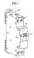
- FIG 1 a perspective view of a single pole plus neutral residual circuit breaker 100 having a toggle 110 is depicted. As illustrated, the circuit breaker 100 includes both single pole and neutral conduction paths.
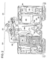
- FIG. 2 depicts a cut-away view of a first face of a single pole plus neutral residual circuit breaker 100, according to an example embodiment.
- the first face of the circuit breaker (not illustrated in FIG. 1 ) includes a first portion 210 and second portion 220 of the housing 102.
- the first portion 210 includes the MCB components of the circuit breaker.
- the second portion 220 includes the residual current device RCD components of the circuit breaker.
- a third portion 230 includes contact mechanism components including fixed and mobile contacts, bimetallic strip, and toggle components.
- a compacted single pole plus neutral residual circuit breaker includes a MCB components portion 210, a contact mechanism component portion 230 proximate the MCB components portion 210, and an RCD components portion 230 proximate the contact mechanism components portion 220.
- the circuit breaker 100 includes clamp 201 and contact 202 within the second portion 220 of the circuit breaker 100.
- the contact 202 provides for a conduction path for the single pole 114 to components within the circuit breaker 100.
- the circuit breaker 100 further includes core 203 disposed within the second portion 220. The winding 240 about the core 203 provides a conduction path for the single pole 114 of the circuit breaker 100.
- the circuit breaker 100 further includes mobile contact mechanism 206 in mechanical communication with strip 209, and arranged to rest on support 207. If the strip 209 exceeds a threshold temperature which is based upon the material-make-up of the strip, the strip 209 disturbs the mobile contact mechanism 206 thereby severing electrical communication through disruption of the current path at mobile contact 304 (illustrated in FIG. 3 ).
- the circuit breaker 100 further includes coil 208 in communication with the mobile contact 206 (illustrated in FIG. 2 ), which also provides a portion of the conduction path.
- the coil 208 is disposed to generate a signal indicative of the current carried in the conduction path to determine if the current threshold is exceeded.
- the coil 208 provides overcurrent detection while the core 203 provides leakage current detection.
- the circuit breaker 100 further includes arc extinction portion 213 in communication with fixed contact 207 (illustrated in FIG. 2 ).
- the arc extinction portion 213 is disposed to extinguish, prevent, or reduce an electrical arc which may form due to separation of mobile contact 206 and fixed contact 207.
- mechanical linkages 250 are provided which "trip” or “set” the circuit breaker 100, and also provide separation of mobile contact 206 and fixed contact 207 during an overcurrent event.
- the linkage 254 mechanically links the toggle 110 with the mobile contact 206 through interim linkage 255.
- the tensile spring 253 provides for force between the interim linkage 255 and the mobile contact 206 such that contact separation occurs if the toggle 110 is moved into an "off position” (it is noted that an "on position” is shown for clarity).
- the tripping linkage 251 is also in mechanical communication with mobile contact 206 and fixed contact 207 and provides for contact separation in response to an overcurrent event.
- the tripping linkage 251 is also in mechanical communication with tripping relay 303 (illustrated in FIG. 3 ). With regards to separation of mobile contact 206 and fixed contact 207 in response to leakage current detection above desired levels, it is submitted that mechanical linkages 250 provide separation of mobile contact 304 and fixed contact 305 in response to mechanical action of the tripping relay 303.
- the circuit breaker 100 includes neutral clamp 301 and contact 302 within the first portion 210 of the circuit breaker 100.
- the neutral contact 302 provides for an additional conduction path for the neutral pole 113 to communicate with an external connection from the circuit breaker 100.
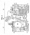
- FIG. 3 a cut away view of the circuit breaker 100 is depicted.
- the components in FIG. 3 define a portion of neutral pole of the circuit breaker 100, and a portion of the single pole of the circuit breaker 100.
- the circuit breaker 100 includes single pole clamp 301 and single pole contact 302 within the second portion 220 of the circuit breaker 100.
- the single pole contact 302 provides for a conduction path for the single pole to components within the circuit breaker 100.
- the circuit breaker 100 further includes core 203 disposed within the second portion 220. The second winding 230 about the core 203 provides a neutral conduction path for the neutral pole of the circuit breaker 100.
- the circuit breaker 100 further includes tripping relay 303 disposed within the second portion 220.
- the tripping relay 303 may be controlled through PCB 204 (illustrated in FIG. 2 ).
- the circuit breaker 100 further includes mobile contact 304 in communication with the second winding 230. Further, the mobile contact 304 may be in severable communication with fixed contact 305. The mobile contact 304 may also provide a portion of the conduction path. Also, the fixed contact 305 may also provide a portion of conduction path. If the current carried within conduction path exceeds a given or desired threshold, the mobile contact 304 separates from fixed contact 305 thereby severing electrical communication between the mobile contact 304 and the fixed contact 305.
- mechanical linkages 250 ( FIG. 2 ) are provided which "trip” or “set” the circuit breaker 100, and also provide separation of mobile contact 304 and fixed contact 305 during an overcurrent event.
- the mobile contact 304 may be in mechanical communication with the mechanical linkages 250 such that tripping may occur at substantially the same time as the tripping described above with regards to FIG. 2 .
- the orientation and electrical connections to these clamps/terminals and conduction paths may be altered relatively easily according to any desired implementation.
- the neutral clamps and conduction path noted above may be swapped with associated single pole clamps and conduction path through manipulation of connections to the clamps.
- the core 203 is disposed to detect an imbalance which results from leakage current, it is not necessary for either the primary or secondary windings 230 and 240 to be fixed as neutral or single pole conduction paths.
- example embodiments should not be limited to the particular orientation of each clamp and conduction path shown, but should include any suitable modification which offers substantially similar operation including overcurrent detection at a first longitudinal portion and leakage current detection at a second longitudinal portion of the circuit breaker 100.
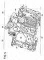
- FIGS. 5-6 illustrate cut-away perspective views of the circuit breaker 100, according to an example embodiment.
- the second portion 220 of the circuit breaker 100 includes the RCD components configured to detect leakage current associated with the circuit breaker 100.
- the first longitudinal portion includes the MCB components configured to detect overcurrent conditions.
- the third longitudinal portion 230 proximate both the first and second longitudinal portions 210 and 220, includes contact mechanism components configured to trip and/or open/close the circuit breaker 100 in response to an overcurrent condition or current imbalance (i.e., leakage current condition).
- conduction paths of the circuit breaker 100 are arranged to allow arrangement of both MCB and RCD components within a single module housing. Through intelligent routing of these conduction paths, both the single pole and neutral pole of the circuit breaker 100 may be included in a single module of width 1 W while also providing leakage current detection. Both micro circuit breaker components, contact mechanism components, and residual current device components are distributed across three longitudinal portions, allowing tripping of the circuit breaker from both the MCB components and RCD components though the same contact mechanism, thereby saving space.
- example embodiments provide a single module circuit breaker configured to provide both overcurrent and leakage current protection within a single module of width 1 W.
- FIG. 7 depicts a compacted core of a single pole plus neutral residual circuit breaker, according to an example embodiment.
- the compacted core 203 may be arranged within the second portion 220 of the circuit breaker such that the PCB 204 and the trip relay 303 may be arranged in the second portion 220.
- Primary and secondary windings are arranged around and within the compacted core to facilitate current-imbalance detection through the PCB.
- the PCB provides, to the tripping relay, a signal indicative of the condition.
- the tripping relay disturbs the contact mechanism components of the third longitudinal portion 230 of the circuit breaker thereby providing leakage current protection.
Landscapes
- Engineering & Computer Science (AREA)
- Power Engineering (AREA)
- Breakers (AREA)
Applications Claiming Priority (1)
| Application Number | Priority Date | Filing Date | Title |
|---|---|---|---|
| US13/075,530 US20120250206A1 (en) | 2011-03-30 | 2011-03-30 | Compact residual current breaker with overcurrent protection |
Publications (2)
| Publication Number | Publication Date |
|---|---|
| EP2506283A1 true EP2506283A1 (fr) | 2012-10-03 |
| EP2506283B1 EP2506283B1 (fr) | 2016-06-29 |
Family
ID=45999615
Family Applications (1)
| Application Number | Title | Priority Date | Filing Date |
|---|---|---|---|
| EP12161902.7A Active EP2506283B1 (fr) | 2011-03-30 | 2012-03-28 | Disjoncteur de courant résiduel compact avec protection contre les surintensités |
Country Status (2)
| Country | Link |
|---|---|
| US (1) | US20120250206A1 (fr) |
| EP (1) | EP2506283B1 (fr) |
Cited By (3)
| Publication number | Priority date | Publication date | Assignee | Title |
|---|---|---|---|---|
| EP3385974A1 (fr) * | 2017-04-06 | 2018-10-10 | Siemens Aktiengesellschaft | Disjoncteur différentiel |
| EP4064313A1 (fr) | 2021-03-26 | 2022-09-28 | Schneider Electric Industries SAS | Dispositif de protection électrique et tableau électrique comprenant un tel dispositif de protection électrique |
| EP4064316A1 (fr) | 2021-03-26 | 2022-09-28 | Schneider Electric Industries SAS | Dispositif de protection électrique et tableau électrique comprenant un tel dispositif de protection électrique |
Families Citing this family (3)
| Publication number | Priority date | Publication date | Assignee | Title |
|---|---|---|---|---|
| DE102016105341B4 (de) * | 2016-03-22 | 2022-05-25 | Eaton Intelligent Power Limited | Schutzschaltgerät |
| DE102017101723A1 (de) | 2017-01-30 | 2018-08-02 | Abb Schweiz Ag | Elektrisches Installationsschaltgerät mit einer Abluftöffnung |
| CN112397350B (zh) * | 2020-10-19 | 2025-03-11 | 浙江正泰电器股份有限公司 | 一种电子式剩余电流动作断路器 |
Citations (3)
| Publication number | Priority date | Publication date | Assignee | Title |
|---|---|---|---|---|
| US5089796A (en) * | 1990-09-19 | 1992-02-18 | Square D Company | Earth leakage trip indicator |
| EP0962952A1 (fr) * | 1998-06-04 | 1999-12-08 | Schneider Electric Industries SA | Electric power cut-off device comprising a differential release device and a circuit breaker equiped with such a device |
| EP2242080A2 (fr) * | 2009-04-18 | 2010-10-20 | General Electric Company | Ensemble de test pour disjoncteur |
Family Cites Families (6)
| Publication number | Priority date | Publication date | Assignee | Title |
|---|---|---|---|---|
| US3566189A (en) * | 1969-03-18 | 1971-02-23 | Airpax Electronics | Circuit breaker with loosely coupled deenergizing means for high overload currents |
| US4000444A (en) * | 1971-05-07 | 1976-12-28 | 3-M Company | Electric circuit breaker with ground fault protection |
| GB0226111D0 (en) * | 2002-11-08 | 2002-12-18 | Delta Electrical Ltd | Residual current devices |
| DE102007040875B4 (de) * | 2007-08-29 | 2017-11-16 | Austriamicrosystems Ag | Schaltungsanordnung zum Schutz vor elektrostatischen Entladungen und Verfahren zum Betreiben einer solchen |
| US7994882B2 (en) * | 2009-04-18 | 2011-08-09 | General Electric Company | Space allocation within a circuit breaker |
| US8729950B2 (en) * | 2012-05-30 | 2014-05-20 | Fairchild Semiconductor Corporation | High voltage clamp circuit |
-
2011
- 2011-03-30 US US13/075,530 patent/US20120250206A1/en not_active Abandoned
-
2012
- 2012-03-28 EP EP12161902.7A patent/EP2506283B1/fr active Active
Patent Citations (3)
| Publication number | Priority date | Publication date | Assignee | Title |
|---|---|---|---|---|
| US5089796A (en) * | 1990-09-19 | 1992-02-18 | Square D Company | Earth leakage trip indicator |
| EP0962952A1 (fr) * | 1998-06-04 | 1999-12-08 | Schneider Electric Industries SA | Electric power cut-off device comprising a differential release device and a circuit breaker equiped with such a device |
| EP2242080A2 (fr) * | 2009-04-18 | 2010-10-20 | General Electric Company | Ensemble de test pour disjoncteur |
Cited By (8)
| Publication number | Priority date | Publication date | Assignee | Title |
|---|---|---|---|---|
| EP3385974A1 (fr) * | 2017-04-06 | 2018-10-10 | Siemens Aktiengesellschaft | Disjoncteur différentiel |
| CN108695115A (zh) * | 2017-04-06 | 2018-10-23 | 西门子公司 | 剩余电流动作断路器 |
| CN108695115B (zh) * | 2017-04-06 | 2020-05-26 | 西门子公司 | 剩余电流动作断路器 |
| EP4064313A1 (fr) | 2021-03-26 | 2022-09-28 | Schneider Electric Industries SAS | Dispositif de protection électrique et tableau électrique comprenant un tel dispositif de protection électrique |
| EP4064316A1 (fr) | 2021-03-26 | 2022-09-28 | Schneider Electric Industries SAS | Dispositif de protection électrique et tableau électrique comprenant un tel dispositif de protection électrique |
| FR3121274A1 (fr) | 2021-03-26 | 2022-09-30 | Schneider Electric Industries Sas | Dispositif de protection électrique et tableau électrique comprenant un tel dispositif de protection électrique |
| FR3121273A1 (fr) | 2021-03-26 | 2022-09-30 | Schneider Electric Industries Sas | Dispositif de protection électrique et tableau électrique comprenant un tel dispositif de protection électrique |
| EP4718493A2 (fr) | 2021-03-26 | 2026-04-01 | Schneider Electric Industries Sas | Dispositif de protection électrique et tableau électrique comprenant un tel dispositif de protection électrique |
Also Published As
| Publication number | Publication date |
|---|---|
| US20120250206A1 (en) | 2012-10-04 |
| EP2506283B1 (fr) | 2016-06-29 |
Similar Documents
| Publication | Publication Date | Title |
|---|---|---|
| US8154831B2 (en) | Leakage current detection interrupter with fire protection means | |
| EP2506283B1 (fr) | Disjoncteur de courant résiduel compact avec protection contre les surintensités | |
| JP4606952B2 (ja) | 電圧サージ保護装置 | |
| EP1939912B1 (fr) | Activation pour appareil de commutation | |
| CN101965620B (zh) | 漏电断路器 | |
| EP2242077B1 (fr) | Attribution d'espace dans un disjoncteur | |
| JP2008159456A (ja) | 漏電遮断器 | |
| EP2455961B1 (fr) | Dispositif de commutation électrique | |
| EP1814133B1 (fr) | Dispositif de coupe-circuit | |
| CN102792406A (zh) | 包括一定数量气体通道的限制器以及使用这种限制器的电气开关设备 | |
| CN202871718U (zh) | 电路中断装置和用于与断路器一起使用的脱扣机构 | |
| CN111834170A (zh) | 紧凑型保护开关设备 | |
| CN203553079U (zh) | 两极集成多功能断路器 | |
| CN101443874B (zh) | 单极断路器的壳体 | |
| KR200266485Y1 (ko) | 가정용 소형 차단기 | |
| EP2966664A1 (fr) | Dispositifs électriques à courant limité, ensembles de contact d'un dispositif électrique et procédés d'exploitation | |
| CN118675946A (zh) | 设备模块、串接组装设备和接触弹簧 | |
| KR102159006B1 (ko) | 공용 순시 트립 장치가 구비된 차단기 | |
| CN101728127A (zh) | 低压双极自动断路器 | |
| US12437950B2 (en) | Plug-in summation current transformer module, rail-mounted device, and assembly method | |
| KR200234477Y1 (ko) | 영상 변류기가 내장된 배선용 차단기 | |
| JP2677866B2 (ja) | 負荷保護装置 | |
| CN116435149A (zh) | 低压保护开关设备和组装方法 | |
| CN119208098A (zh) | 电气保护装置 | |
| JP2007317382A (ja) | 漏電遮断器 |
Legal Events
| Date | Code | Title | Description |
|---|---|---|---|
| PUAI | Public reference made under article 153(3) epc to a published international application that has entered the european phase |
Free format text: ORIGINAL CODE: 0009012 |
|
| AK | Designated contracting states |
Kind code of ref document: A1 Designated state(s): AL AT BE BG CH CY CZ DE DK EE ES FI FR GB GR HR HU IE IS IT LI LT LU LV MC MK MT NL NO PL PT RO RS SE SI SK SM TR |
|
| AX | Request for extension of the european patent |
Extension state: BA ME |
|
| 17P | Request for examination filed |
Effective date: 20130403 |
|
| 17Q | First examination report despatched |
Effective date: 20150714 |
|
| GRAP | Despatch of communication of intention to grant a patent |
Free format text: ORIGINAL CODE: EPIDOSNIGR1 |
|
| INTG | Intention to grant announced |
Effective date: 20160311 |
|
| GRAS | Grant fee paid |
Free format text: ORIGINAL CODE: EPIDOSNIGR3 |
|
| GRAA | (expected) grant |
Free format text: ORIGINAL CODE: 0009210 |
|
| AK | Designated contracting states |
Kind code of ref document: B1 Designated state(s): AL AT BE BG CH CY CZ DE DK EE ES FI FR GB GR HR HU IE IS IT LI LT LU LV MC MK MT NL NO PL PT RO RS SE SI SK SM TR |
|
| REG | Reference to a national code |
Ref country code: GB Ref legal event code: FG4D |
|
| REG | Reference to a national code |
Ref country code: CH Ref legal event code: EP |
|
| REG | Reference to a national code |
Ref country code: AT Ref legal event code: REF Ref document number: 809689 Country of ref document: AT Kind code of ref document: T Effective date: 20160715 |
|
| REG | Reference to a national code |
Ref country code: IE Ref legal event code: FG4D |
|
| REG | Reference to a national code |
Ref country code: DE Ref legal event code: R096 Ref document number: 602012019888 Country of ref document: DE |
|
| REG | Reference to a national code |
Ref country code: LT Ref legal event code: MG4D |
|
| PG25 | Lapsed in a contracting state [announced via postgrant information from national office to epo] |
Ref country code: LT Free format text: LAPSE BECAUSE OF FAILURE TO SUBMIT A TRANSLATION OF THE DESCRIPTION OR TO PAY THE FEE WITHIN THE PRESCRIBED TIME-LIMIT Effective date: 20160629 Ref country code: NO Free format text: LAPSE BECAUSE OF FAILURE TO SUBMIT A TRANSLATION OF THE DESCRIPTION OR TO PAY THE FEE WITHIN THE PRESCRIBED TIME-LIMIT Effective date: 20160929 Ref country code: FI Free format text: LAPSE BECAUSE OF FAILURE TO SUBMIT A TRANSLATION OF THE DESCRIPTION OR TO PAY THE FEE WITHIN THE PRESCRIBED TIME-LIMIT Effective date: 20160629 |
|
| REG | Reference to a national code |
Ref country code: NL Ref legal event code: MP Effective date: 20160629 |
|
| PG25 | Lapsed in a contracting state [announced via postgrant information from national office to epo] |
Ref country code: RS Free format text: LAPSE BECAUSE OF FAILURE TO SUBMIT A TRANSLATION OF THE DESCRIPTION OR TO PAY THE FEE WITHIN THE PRESCRIBED TIME-LIMIT Effective date: 20160629 Ref country code: NL Free format text: LAPSE BECAUSE OF FAILURE TO SUBMIT A TRANSLATION OF THE DESCRIPTION OR TO PAY THE FEE WITHIN THE PRESCRIBED TIME-LIMIT Effective date: 20160629 Ref country code: GR Free format text: LAPSE BECAUSE OF FAILURE TO SUBMIT A TRANSLATION OF THE DESCRIPTION OR TO PAY THE FEE WITHIN THE PRESCRIBED TIME-LIMIT Effective date: 20160930 Ref country code: HR Free format text: LAPSE BECAUSE OF FAILURE TO SUBMIT A TRANSLATION OF THE DESCRIPTION OR TO PAY THE FEE WITHIN THE PRESCRIBED TIME-LIMIT Effective date: 20160629 Ref country code: SE Free format text: LAPSE BECAUSE OF FAILURE TO SUBMIT A TRANSLATION OF THE DESCRIPTION OR TO PAY THE FEE WITHIN THE PRESCRIBED TIME-LIMIT Effective date: 20160629 Ref country code: LV Free format text: LAPSE BECAUSE OF FAILURE TO SUBMIT A TRANSLATION OF THE DESCRIPTION OR TO PAY THE FEE WITHIN THE PRESCRIBED TIME-LIMIT Effective date: 20160629 |
|
| REG | Reference to a national code |
Ref country code: AT Ref legal event code: MK05 Ref document number: 809689 Country of ref document: AT Kind code of ref document: T Effective date: 20160629 |
|
| PG25 | Lapsed in a contracting state [announced via postgrant information from national office to epo] |
Ref country code: CZ Free format text: LAPSE BECAUSE OF FAILURE TO SUBMIT A TRANSLATION OF THE DESCRIPTION OR TO PAY THE FEE WITHIN THE PRESCRIBED TIME-LIMIT Effective date: 20160629 Ref country code: SK Free format text: LAPSE BECAUSE OF FAILURE TO SUBMIT A TRANSLATION OF THE DESCRIPTION OR TO PAY THE FEE WITHIN THE PRESCRIBED TIME-LIMIT Effective date: 20160629 Ref country code: IS Free format text: LAPSE BECAUSE OF FAILURE TO SUBMIT A TRANSLATION OF THE DESCRIPTION OR TO PAY THE FEE WITHIN THE PRESCRIBED TIME-LIMIT Effective date: 20161029 Ref country code: RO Free format text: LAPSE BECAUSE OF FAILURE TO SUBMIT A TRANSLATION OF THE DESCRIPTION OR TO PAY THE FEE WITHIN THE PRESCRIBED TIME-LIMIT Effective date: 20160629 Ref country code: EE Free format text: LAPSE BECAUSE OF FAILURE TO SUBMIT A TRANSLATION OF THE DESCRIPTION OR TO PAY THE FEE WITHIN THE PRESCRIBED TIME-LIMIT Effective date: 20160629 |
|
| PG25 | Lapsed in a contracting state [announced via postgrant information from national office to epo] |
Ref country code: AT Free format text: LAPSE BECAUSE OF FAILURE TO SUBMIT A TRANSLATION OF THE DESCRIPTION OR TO PAY THE FEE WITHIN THE PRESCRIBED TIME-LIMIT Effective date: 20160629 Ref country code: PT Free format text: LAPSE BECAUSE OF FAILURE TO SUBMIT A TRANSLATION OF THE DESCRIPTION OR TO PAY THE FEE WITHIN THE PRESCRIBED TIME-LIMIT Effective date: 20161031 Ref country code: PL Free format text: LAPSE BECAUSE OF FAILURE TO SUBMIT A TRANSLATION OF THE DESCRIPTION OR TO PAY THE FEE WITHIN THE PRESCRIBED TIME-LIMIT Effective date: 20160629 Ref country code: SM Free format text: LAPSE BECAUSE OF FAILURE TO SUBMIT A TRANSLATION OF THE DESCRIPTION OR TO PAY THE FEE WITHIN THE PRESCRIBED TIME-LIMIT Effective date: 20160629 Ref country code: BE Free format text: LAPSE BECAUSE OF FAILURE TO SUBMIT A TRANSLATION OF THE DESCRIPTION OR TO PAY THE FEE WITHIN THE PRESCRIBED TIME-LIMIT Effective date: 20160629 Ref country code: ES Free format text: LAPSE BECAUSE OF FAILURE TO SUBMIT A TRANSLATION OF THE DESCRIPTION OR TO PAY THE FEE WITHIN THE PRESCRIBED TIME-LIMIT Effective date: 20160629 |
|
| REG | Reference to a national code |
Ref country code: FR Ref legal event code: PLFP Year of fee payment: 6 |
|
| REG | Reference to a national code |
Ref country code: DE Ref legal event code: R097 Ref document number: 602012019888 Country of ref document: DE |
|
| PLBE | No opposition filed within time limit |
Free format text: ORIGINAL CODE: 0009261 |
|
| STAA | Information on the status of an ep patent application or granted ep patent |
Free format text: STATUS: NO OPPOSITION FILED WITHIN TIME LIMIT |
|
| PG25 | Lapsed in a contracting state [announced via postgrant information from national office to epo] |
Ref country code: DK Free format text: LAPSE BECAUSE OF FAILURE TO SUBMIT A TRANSLATION OF THE DESCRIPTION OR TO PAY THE FEE WITHIN THE PRESCRIBED TIME-LIMIT Effective date: 20160629 |
|
| 26N | No opposition filed |
Effective date: 20170330 |
|
| PG25 | Lapsed in a contracting state [announced via postgrant information from national office to epo] |
Ref country code: SI Free format text: LAPSE BECAUSE OF FAILURE TO SUBMIT A TRANSLATION OF THE DESCRIPTION OR TO PAY THE FEE WITHIN THE PRESCRIBED TIME-LIMIT Effective date: 20160629 Ref country code: BG Free format text: LAPSE BECAUSE OF FAILURE TO SUBMIT A TRANSLATION OF THE DESCRIPTION OR TO PAY THE FEE WITHIN THE PRESCRIBED TIME-LIMIT Effective date: 20160929 |
|
| REG | Reference to a national code |
Ref country code: CH Ref legal event code: PL |
|
| GBPC | Gb: european patent ceased through non-payment of renewal fee |
Effective date: 20170328 |
|
| PG25 | Lapsed in a contracting state [announced via postgrant information from national office to epo] |
Ref country code: MC Free format text: LAPSE BECAUSE OF FAILURE TO SUBMIT A TRANSLATION OF THE DESCRIPTION OR TO PAY THE FEE WITHIN THE PRESCRIBED TIME-LIMIT Effective date: 20160629 |
|
| REG | Reference to a national code |
Ref country code: IE Ref legal event code: MM4A |
|
| PG25 | Lapsed in a contracting state [announced via postgrant information from national office to epo] |
Ref country code: LU Free format text: LAPSE BECAUSE OF NON-PAYMENT OF DUE FEES Effective date: 20170328 |
|
| PG25 | Lapsed in a contracting state [announced via postgrant information from national office to epo] |
Ref country code: LI Free format text: LAPSE BECAUSE OF NON-PAYMENT OF DUE FEES Effective date: 20170331 Ref country code: GB Free format text: LAPSE BECAUSE OF NON-PAYMENT OF DUE FEES Effective date: 20170328 Ref country code: CH Free format text: LAPSE BECAUSE OF NON-PAYMENT OF DUE FEES Effective date: 20170331 Ref country code: IE Free format text: LAPSE BECAUSE OF NON-PAYMENT OF DUE FEES Effective date: 20170328 |
|
| REG | Reference to a national code |
Ref country code: FR Ref legal event code: PLFP Year of fee payment: 7 |
|
| PG25 | Lapsed in a contracting state [announced via postgrant information from national office to epo] |
Ref country code: MT Free format text: LAPSE BECAUSE OF NON-PAYMENT OF DUE FEES Effective date: 20170328 |
|
| PG25 | Lapsed in a contracting state [announced via postgrant information from national office to epo] |
Ref country code: AL Free format text: LAPSE BECAUSE OF FAILURE TO SUBMIT A TRANSLATION OF THE DESCRIPTION OR TO PAY THE FEE WITHIN THE PRESCRIBED TIME-LIMIT Effective date: 20160629 |
|
| PG25 | Lapsed in a contracting state [announced via postgrant information from national office to epo] |
Ref country code: HU Free format text: LAPSE BECAUSE OF FAILURE TO SUBMIT A TRANSLATION OF THE DESCRIPTION OR TO PAY THE FEE WITHIN THE PRESCRIBED TIME-LIMIT; INVALID AB INITIO Effective date: 20120328 |
|
| PG25 | Lapsed in a contracting state [announced via postgrant information from national office to epo] |
Ref country code: CY Free format text: LAPSE BECAUSE OF NON-PAYMENT OF DUE FEES Effective date: 20160629 |
|
| PG25 | Lapsed in a contracting state [announced via postgrant information from national office to epo] |
Ref country code: MK Free format text: LAPSE BECAUSE OF FAILURE TO SUBMIT A TRANSLATION OF THE DESCRIPTION OR TO PAY THE FEE WITHIN THE PRESCRIBED TIME-LIMIT Effective date: 20160629 |
|
| PG25 | Lapsed in a contracting state [announced via postgrant information from national office to epo] |
Ref country code: TR Free format text: LAPSE BECAUSE OF FAILURE TO SUBMIT A TRANSLATION OF THE DESCRIPTION OR TO PAY THE FEE WITHIN THE PRESCRIBED TIME-LIMIT Effective date: 20160629 |
|
| REG | Reference to a national code |
Ref country code: DE Ref legal event code: R081 Ref document number: 602012019888 Country of ref document: DE Owner name: ABB SCHWEIZ AG, CH Free format text: FORMER OWNER: GENERAL ELECTRIC COMPANY, NEW YORK, N.Y., US |
|
| REG | Reference to a national code |
Ref country code: DE Ref legal event code: R082 Ref document number: 602012019888 Country of ref document: DE Representative=s name: ZIMMERMANN & PARTNER PATENTANWAELTE MBB, DE |
|
| PGFP | Annual fee paid to national office [announced via postgrant information from national office to epo] |
Ref country code: DE Payment date: 20260319 Year of fee payment: 15 |
|
| PGFP | Annual fee paid to national office [announced via postgrant information from national office to epo] |
Ref country code: IT Payment date: 20260324 Year of fee payment: 15 |
|
| PGFP | Annual fee paid to national office [announced via postgrant information from national office to epo] |
Ref country code: FR Payment date: 20260320 Year of fee payment: 15 |