EP2506586A2 - Stereoskopische Anzeigevorrichtung - Google Patents
Stereoskopische Anzeigevorrichtung Download PDFInfo
- Publication number
- EP2506586A2 EP2506586A2 EP12157124A EP12157124A EP2506586A2 EP 2506586 A2 EP2506586 A2 EP 2506586A2 EP 12157124 A EP12157124 A EP 12157124A EP 12157124 A EP12157124 A EP 12157124A EP 2506586 A2 EP2506586 A2 EP 2506586A2
- Authority
- EP
- European Patent Office
- Prior art keywords
- image
- eye
- distance
- inter
- eye image
- Prior art date
- Legal status (The legal status is an assumption and is not a legal conclusion. Google has not performed a legal analysis and makes no representation as to the accuracy of the status listed.)
- Withdrawn
Links
Images


Classifications
-
- G—PHYSICS
- G02—OPTICS
- G02B—OPTICAL ELEMENTS, SYSTEMS OR APPARATUS
- G02B30/00—Optical systems or apparatus for producing three-dimensional [3D] effects, e.g. stereoscopic images
- G02B30/20—Optical systems or apparatus for producing three-dimensional [3D] effects, e.g. stereoscopic images by providing first and second parallax images to an observer's left and right eyes
- G02B30/22—Optical systems or apparatus for producing three-dimensional [3D] effects, e.g. stereoscopic images by providing first and second parallax images to an observer's left and right eyes of the stereoscopic type
- G02B30/25—Optical systems or apparatus for producing three-dimensional [3D] effects, e.g. stereoscopic images by providing first and second parallax images to an observer's left and right eyes of the stereoscopic type using polarisation techniques
-
- A—HUMAN NECESSITIES
- A61—MEDICAL OR VETERINARY SCIENCE; HYGIENE
- A61B—DIAGNOSIS; SURGERY; IDENTIFICATION
- A61B6/00—Apparatus or devices for radiation diagnosis; Apparatus or devices for radiation diagnosis combined with radiation therapy equipment
- A61B6/02—Arrangements for diagnosis sequentially in different planes; Stereoscopic radiation diagnosis
- A61B6/022—Stereoscopic imaging
-
- A—HUMAN NECESSITIES
- A61—MEDICAL OR VETERINARY SCIENCE; HYGIENE
- A61B—DIAGNOSIS; SURGERY; IDENTIFICATION
- A61B6/00—Apparatus or devices for radiation diagnosis; Apparatus or devices for radiation diagnosis combined with radiation therapy equipment
- A61B6/46—Arrangements for interfacing with the operator or the patient
- A61B6/461—Displaying means of special interest
- A61B6/466—Displaying means of special interest adapted to display 3D data
-
- H—ELECTRICITY
- H04—ELECTRIC COMMUNICATION TECHNIQUE
- H04N—PICTORIAL COMMUNICATION, e.g. TELEVISION
- H04N13/00—Stereoscopic video systems; Multi-view video systems; Details thereof
- H04N13/10—Processing, recording or transmission of stereoscopic or multi-view image signals
- H04N13/106—Processing image signals
- H04N13/128—Adjusting depth or disparity
-
- H—ELECTRICITY
- H04—ELECTRIC COMMUNICATION TECHNIQUE
- H04N—PICTORIAL COMMUNICATION, e.g. TELEVISION
- H04N13/00—Stereoscopic video systems; Multi-view video systems; Details thereof
- H04N13/20—Image signal generators
- H04N13/204—Image signal generators using stereoscopic image cameras
- H04N13/207—Image signal generators using stereoscopic image cameras using a single two-dimensional [2D] image sensor
- H04N13/221—Image signal generators using stereoscopic image cameras using a single two-dimensional [2D] image sensor using the relative movement between cameras and objects
-
- H—ELECTRICITY
- H04—ELECTRIC COMMUNICATION TECHNIQUE
- H04N—PICTORIAL COMMUNICATION, e.g. TELEVISION
- H04N13/00—Stereoscopic video systems; Multi-view video systems; Details thereof
- H04N13/20—Image signal generators
- H04N13/204—Image signal generators using stereoscopic image cameras
- H04N13/254—Image signal generators using stereoscopic image cameras in combination with electromagnetic radiation sources for illuminating objects
-
- H—ELECTRICITY
- H04—ELECTRIC COMMUNICATION TECHNIQUE
- H04N—PICTORIAL COMMUNICATION, e.g. TELEVISION
- H04N13/00—Stereoscopic video systems; Multi-view video systems; Details thereof
- H04N13/30—Image reproducers
- H04N13/332—Displays for viewing with the aid of special glasses or head-mounted displays [HMD]
- H04N13/337—Displays for viewing with the aid of special glasses or head-mounted displays [HMD] using polarisation multiplexing
-
- H—ELECTRICITY
- H04—ELECTRIC COMMUNICATION TECHNIQUE
- H04N—PICTORIAL COMMUNICATION, e.g. TELEVISION
- H04N13/00—Stereoscopic video systems; Multi-view video systems; Details thereof
- H04N13/30—Image reproducers
- H04N13/398—Synchronisation thereof; Control thereof
-
- H—ELECTRICITY
- H04—ELECTRIC COMMUNICATION TECHNIQUE
- H04N—PICTORIAL COMMUNICATION, e.g. TELEVISION
- H04N13/00—Stereoscopic video systems; Multi-view video systems; Details thereof
- H04N13/30—Image reproducers
- H04N13/366—Image reproducers using viewer tracking
- H04N13/373—Image reproducers using viewer tracking for tracking forward-backward translational head movements, i.e. longitudinal movements
Definitions
- This invention relates to a stereoscopic display apparatus that performs a stereoscopic display using a right-eye image and a left-eye image acquired through radiography (stereoscopic photography).
- the invention of a stereoscopic display apparatus of a radiographic image that irradiates a subject with radiation from different angles, that acquires (stereoscopically photographs) a right-eye image and a left-eye image, and that performs a stereoscopic display using the acquired images is known.
- An object of the present invention is to provide a stereoscopic display apparatus which can simply change the depth of a stereoscopic display in a right-eye image and a left-eye image radiographed (stereoscopically photographed) for the purpose of a stereoscopic display.
- the resent invention provides a stereoscopic display apparatus that performs a stereoscopic display using a right-eye image and a left-eye image acquired by radiographing a subject plural times while changing an incidence angle of radiation on the subject, comprising:
- the inter-image distance includes a first inter-image distance and a second inter-image distance, the first inter-image distance being calculated on the basis of radiographic conditions of the right-eye image and the left-eye image, and the second inter-image distance being calculated on the basis of the radiographic conditions, and observation conditions, display conditions and image processing conditions of the stereoscopic display, and wherein the range of the inter-image distance which can be changed by the changing means is calculated on the basis of the first inter-image distance and the second inter-image distance.
- warning means that gives a warning when the inter-image distance is out of the changeable range of the inter-image distance by the changing means.
- the warning of the warning means includes at least one of stopping the changing of the inter-image distance and displaying the purport thereof.
- the radiographic conditions includes a radiation source-image reception plane distance (SID) D, an irradiation angle of a radiation source (a rotation angle of a radiation source arm) ⁇ 1 and ⁇ 2 ( ⁇ 1 ⁇ 2 ), a pressing thickness (a radiographic stand-pressing plate surface distance) l p , and a case thickness (a radiographic stand-image reception plane distance) l c
- the range of the first inter-image distance x m is expressed by: 1 c • Dsin ⁇ ⁇ 2 • Dcos ⁇ ⁇ 1 - 1 c - 1 c • Dsin ⁇ ⁇ 1 • Dcos ⁇ ⁇ 2 - 1 c Dcos ⁇ ⁇ 1 - 1 c ⁇ Dcos ⁇ ⁇ 2 - 1 c ⁇ x m ⁇ 1 p • Dsin ⁇ ⁇ 2 • Dcos ⁇ ⁇ 1 - 1 p - 1 p • Dsin ⁇ ⁇ 2 • Dcos
- the observation conditions include an observation distance VD which is a distance between the display unit and the observer, a binocular distance D eye , an imaging plane distance x, a parallax angle ⁇ 2 (a difference between a binocular angle ⁇ in the display unit and a binocular angle ⁇ at an imaging position), and a right-left parallax d' on the display unit
- the display conditions include an enlargement and reduction ratio based on an inter-pixel distance (pixel size) of the display unit.
- the image processing conditions include a display magnification of the right-eye image and the left-eye image.
- an image difference display area in which the inter-image distance between the right-eye image and the left-eye image is displayed by the use of thumbnail images
- the changing means changes the distance between the thumbnail images displayed in the image difference display area to adjust the depth of the stereoscopic display.
- the changing means has an automatic control function, and wherein the automatic control function is to automatically change the inter-image distance depending on the radiographic conditions.
- the automatic control function is to change the inter-image distance to any one of a maximum value, a median value, and a minimum value of the range of the changeable inter-image distance.
- an image server that stores a plurality of the inter-image distances between right-eye images and left-eye images which can be stereoscopically displayed
- the changing means has an automatic control function
- the automatic control function is to automatically change the inter-image distance of the present stereoscopic display depending on the inter-image distance of the other stereoscopic displays.
- blanks of the right-eye image and the left-eye image formed by causing the changing means to change the inter-image distance are painted with black.
- the depth of a stereoscopic display can be freely changed in the range in which the stereoscopic view is not destroyed, it is possible to reduce the burden on the eyes when viewing the stereoscopic display, and thus to prevent erroneous diagnosis due to the eye fatigue.
- FIG. 1 is an overview diagram illustrating the entire configuration of an example of a stereoscopic display apparatus according to the present invention.
- FIG. 2 is a block diagram illustrating an example of the system configuration of the stereoscopic display apparatus according to the present invention.
- the stereoscopic display apparatus 10 includes a display unit 12, a pair of polarizing glasses 14, an operation input unit 16, and a console 30.
- the display unit 12 includes a first image display unit 18L, a second image display unit 18R, and a beam splitter mirror 20.
- the display unit 12 performs a stereoscopic display by displaying a left-eye image on the first image display unit 18L and displaying a right-eye image on the second image display unit 18R, and may also display a normal planar display by displaying the same image on the first image display unit 18L and the second image display unit 18R.
- the display unit 12 is observed from an observation position at a predetermined distance from the display unit 12 (predetermined observation conditions) and that an inter-pixel distance (pixel size) of the display unit 12 (the first image display unit 18L and the second image display unit 18R) and an enlargement and reduction ratio are set to predetermined value (predetermined display conditions and image processing conditions).
- the stereoscopic display apparatus 10 is connected, for example, to an image network system such as PACS via an image acquiring unit 50 to be described later of the console 30 as described above and acquires a right-eye image and a left-eye image allowing a stereoscopic view in a radiographic image from an image server 32 included in the image network system.
- the stereoscopic display apparatus 10 may be connected directly to a radiographic imaging system or the like and may acquire a right-eye image and a left-eye image allowing a stereoscopic view.
- the right-eye image and the left-eye image allowing a stereoscopic view are a pair of radiographic images radiographed (stereoscopically photographed) (radiographed under predetermined radiographic conditions) in a state where the irradiation position of radiation, that is, a bulb (radiation source) position, is shifted in a predetermined direction by a predetermined distance in a radiographic imaging apparatus or the like.
- the right-eye image and the left-eye image allowing a stereoscopic view may be a pair of radiographic images radiographed in a state where the irradiation direction of the bulb is shifted or may be a pair of radiographic images radiographed in a state where a subject rotates and an incidence angle of radiation on a subject is changed.
- the acquired right-eye image and left-eye image are subjected to a predetermined image process by an image processing unit 52 to be described later of the console 30 and are displayed on the first image display unit 18L and the second image display unit 18R, respectively, by a display control unit 56 to be described later.
- Optical filters which are not shown in the drawings and which polarize light emitted from the display units in predetermined different directions may be disposed in front of the first image display unit 18L and the second image display unit 18R.
- the first light of the left-eye image displayed on the first image display unit 18L is polarized in a predetermined direction by the optical filter not shown and is reflected by the beam splitter mirror 20.
- the second light of the right-eye image displayed on the second image display unit 18R is polarized in a predetermined direction different from that of the first light by the optical filter not shown and is transmitted by the beam splitter mirror 20.
- the reflected first light and the transmitted second light are changed to combined light having different polarization directions and traveling in the same direction by the beam splitter mirror 20.
- the image processing unit 52 to be described later of the console 30 performs a process of vertically inverting an image on the left-eye image displayed on the first image display unit 18L in advance, in addition to a process of changing an enlargement and reduction ratio.
- the angle of the beam splitter mirror 20 is adjusted and fixed so that the left-eye image displayed on the first image display unit 18L and the right-eye image displayed on the second image display unit 18R overlap with each other when an operator (an observer) at the observation position watches the display unit 12 of the stereoscopic display apparatus 10 from the front side.
- the pair of polarizing glasses 14 transmits the first light from the first image display unit 18L through the use of a left-eye polarizing lens 14L, transmits the second light from the second image display unit 18R through the use of a right-eye polarizing lens 14R, and blocks the other light.
- the left-eye image displayed on the first image display unit 18L is recognized by the left eye of the operator wearing the pair of polarizing glasses 14 and the right-eye image displayed on the second image display unit 18R is recognized by the right eye of the operator.
- a human being recognizes the image as a stereoscopic display. Accordingly, the operator wearing the pair of polarizing glasses 14 observes a stereoscopic display based on the right-eye and the left-eye image by simultaneously recognizing the right-eye image and the left-eye image having parallax by the sue of the right eye and the left eye.
- the operation input unit 16 may be, for example, a pointing device such as a mouse used for operating a computer and cursor 24 to be described later on the display screen recognized by the operator can be freely operated by operating the operation input unit 16.
- the operation input unit 16 is not limited to the mouse, but may further include operation input means such as a keyboard for inputting information in addition to the mouse.
- the cursor 24 to be described later is calculated in position and drawn by the use of the control unit 54 to be described later of the console 30 and is displayed on the first image display unit 18L and the second image display unit 18R through the use of the display control unit 56 to be described later.
- the console 30 includes an image acquiring unit 50, an image processing unit 52, a control unit 54, a display control unit 56, and a storage unit 58.
- the console 30 is specifically constructed by a computer including a CPU (Central Processing Unit), a RAM (Random Access Memory), and a hard disk and the CPU, the RAM, the hard disk, and the like constitute the units of the console 30 in cooperation with each other.
- a CPU Central Processing Unit
- RAM Random Access Memory
- the image acquiring unit 50 acquires image data of a right-eye image and a left-eye image allowing a stereoscopic display from the image server 32 in response to the operation input unit 16 via the control unit 54.
- the image processing unit 52 performs a predetermined image process on the image data of the right-eye image and the left-eye image acquired by the image acquiring unit 50 and outputs image data which can be displayed on the first image display unit 18L and the second image display unit 18R.
- the image processing unit 52 performs an enlargement and reduction process using a predetermined an enlargement and reduction ratio on the right-eye image and the left-eye image on the basis of display software or the like.
- the enlargement and reduction process may be performed on the basis of information of the inter-pixel distance of the display unit 12 (the first image display unit 18L and the second image display unit 18R). As described above, an image process is performed on the left-eye image to be displayed on the first image display unit 18L so as to display a vertically-inverted image.
- the image processing unit 52 may output the image data of the right-eye image and the left-eye image having been subjected to the image process to the storage unit 58 in response to an instruction from the control unit 54.
- Information of the enlargement and reduction ratio of an image can be set by the use of the operation input unit 16.
- the image processing unit 52 may enlarge and reduce the right-eye image and the left-eye image on the basis of the information of the set enlargement and reduction ratio of an image.
- the control unit 54 controls the operations of the image acquiring unit 50, the image processing unit 52, the display control unit 56, and the storage unit 58 in accordance with an instruction from the operation input unit 16 and displays the cursor 24 operated by the use of the operation input unit 16 on both images of the right-eye image and the left-eye image through the use of the display control unit 56.
- the control unit 54 calculates the movable range in the depth direction by changing an image difference (inter-image distance) between the right-eye image and the left-eye image through the use of the image processing unit 52 and the display control unit 56 to be described later or using radiographic conditions.
- the display control unit 56 displays the right-eye image and the left-eye image, which has been subjected to a predetermined image process by the image processing unit 52 and can be displayed, on the first image display unit 18L and the second image display unit 18R in response to an instruction from the control unit 54, and the control unit 54 displays the cursor 24, which is calculated in position and drawn, on the first image display unit 18L and the second image display unit 18R.
- the display control unit 56 may read the image data of the right-eye image and the left-eye image stored in the storage unit 58 in response to an instruction from the control unit 54 and may display the image data on the first image display unit 18L and the second image display unit 18R.
- the storage unit 58 stores the image data of the right-eye image and the left-eye image having been subjected to the predetermined image process by the image processing unit 52 and outputs the image data to the display control unit 56, if necessary, in response to the instruction from the control unit 54.
- the storage unit 58 may output the image data of the stored right-eye image and left-eye image to the image server 32 in response to an instruction from the operation input unit 16 via the control unit 54.
- the storage unit 58 may store radiographic conditions of the right-eye image and the left-eye image, the inter-image distance, the enlargement and reduction ratio of an image, and the like, in addition to the image data of the right-eye image and the left-eye image.
- FIG. 3 is an example of a diagram illustrating a stereoscopic display screen recognized from the display unit 12 (the beam splitter mirror 20) in the stereoscopic display apparatus 10 according to the present invention.
- the stereoscopic display screen of the display unit 12 displays an image display area 22, a cursor 24, an image difference display area 26, and text display areas 28A and 28B.
- the image display area 22 can perform a stereoscopic display and can also performs a planar display including a right-eye image and a left-eye image in response to an instruction input from the operation input unit 16 and in response to an input instruction (an input instruction to the text display areas 28A and 28B to be described later) to the picture (the display unit 12) based on the operation on the cursor 24.
- the image display area 22 can simultaneously perform plural stereoscopic displays and may perform both the stereoscopic display and the planar display.
- the cursor 24 gives an input instruction on the picture as described above and adjusts the stereoscopic display in the image display area in the depth direction by moving (shifting) the thumbnail images of the right-eye image and the left-eye image in the image difference display area 26 to be described later.
- the image difference display area 26 displays by what the right-eye image and the left-eye image overlap separated from each other (an image difference (the inter-image distance) between the right-eye image and the left-eye image) in the stereoscopic display as a positional relationship between the thumbnail image of the left-eye image and the thumbnail image of the right-eye image.
- the operator can confirm by what the right-eye image and the left-eye image are shifted from the original positions by confirming the image difference display area 26.
- the movement of both thumbnail images may be controlled, for example by rotating (scrolling) a wheel 16S of the mouse 16 forward and backward.
- both the thumbnail image of the right-eye image and the thumbnail image of the left-eye image may be moved or only one thereof may be moved.
- the distance between the right-eye image and the left-eye image (the inter-image distance) in the stereoscopic display is changed depending on the distance between the thumbnail images.
- the right-eye image and the left-eye image are images radiographed from different positions for the purpose of the stereoscopic display, an observer can recognize the stereoscopic display by displaying both images are displayed to overlap at the same position, causing the left eye to recognize the left-eye image, and causing the right eye to recognize the right-eye image.
- the positional relationship among the first image display unit 18L, the second image display unit 18R, and the beam splitter mirror 20 is precisely adjusted in advance so as to display both images to overlap at the same position in the image display area 22 when the display unit is observed at the above-mentioned observation position.
- the observer operates the operation input unit 16 to correct the display positions of the right-eye image and the left-eye image by software through the use of the display control unit 56, thereby performing a calibration so as to display both images to overlap at the same position.
- the right-eye image and the left-eye image are displayed to overlap at the same position in the image display area 22 and the thumbnail image of the left-eye image and the thumbnail image of the right-eye image in the image difference display area 26 are displayed to overlap at the same position as described above.
- frames or rectangles representing the right-eye image and the left-eye image may be displayed instead of the thumbnail images. This is because the image difference in the present stereoscopic display has only to be confirmed and has only to be finely adjusted in the depth direction.
- the position of the present stereoscopic display may be represented by a dotted frame line
- the left-eye image may be represented by a blue rectangle
- the right-eye image may be represented by a red rectangle.
- the rectangles may transmit the background and the overlapping area may be displayed with violet in which blue and red are superimposed.
- thumbnail images of the stereoscopic display selected by the use of the cursor 24 are displayed in the image difference display area 26.
- the text display areas 28A and 28B show menus, radiographing information of the right-eye image and the left-eye image, the inter-image distance between the right-eye image and the left-eye image, a warning from warning means to be described later, and the like.
- the text display area 28A in the image display area 22 can show a stereoscopic display and the text display area 28B other than the image display area 22 can show a planar display.
- the stereoscopic display may be changed in the depth direction by interlocking with the right-eye image and the left-eye image or may be changed in the depth direction independently of the right-eye image and the left-eye image.
- Examples of the menus include switching between a stereoscopic display and a planar display in the image display area 22, selection of a display method, storage of a stereoscopic display (a right-eye image, a left-eye image, an inter-image distance therebetween), and storage of the inter-image distance, and the like.
- the operator can point out the menus by the use of the cursor 24.
- a method of displaying a single stereoscopic view in the image display area 22 a method of displaying plural stereoscopic views, a method of showing both a stereoscopic display and a planar display (at least one of a right-eye image and a left-eye image), and the like can be considered as a display method. These display methods can be selected in the menus.
- the right-left direction is defined as an X axis direction (where the right side is positive) and the front-rear direction is defined as a Z axis direction (where the rear side is positive).
- the object A located at the same position in the X axis direction moves away from an observer's viewpoint (when it goes apart in the Z axis direction (for example, moves from the position (D 2 ) in FIG. 4 to the position (D 1 ))
- the object in the left-eye image appears to move to the left side and the object A in the right-eye image appears to move to the right side.
- the right eye and the left eye recognize the objects as the right-eye image and the left-eye image shown in FIG. 5B , respectively.
- the observer is made to view the right-eye image and the left-eye image including the objects B and C shown in FIG. 6A in which the left-eye image is parallel-shifted to the left side from FIG. 5B and the right-eye image is parallel-shifted to the right side from FIG. 5B (that is, the inter-image distance between the right-eye image and the left-eye image is made to increase).
- the objects B and C are parallel-shifted from the position in FIG. 5B indicated by a dotted line to the position indicated by a solid line.
- the observer's brain recognizes the objects B and C are located at the position shown in FIG. 6B deeper than in FIG. 5A .
- the observer's recognition in the depth direction can be shifted.
- the display When the inter-image distance between the right-eye image and the left-eye image varies in the direction parallel to the straight line connecting the observer's right eye and left eye, the display appears to vary in the depth direction. Accordingly, even when the right-eye image and the left-eye image are slightly obliquely moved, the display is adjusted in the depth direction.
- the direction in which the right-eye image and the left-eye image are shifted does not have to be exactly parallel to the direction of the straight line connecting the observer's right eye and left eye, but both directions have only to be substantially parallel to each other so as to change the inter-image distance in the direction of the straight line.
- the stereoscopic display apparatus 10 can cause the observer to recognize a deeper stereoscopic display by causing the image processing unit 52 of the console 30 to slightly shift the right-eye image and the left-eye image allowing a stereoscopic view to the right side and the left side, respectively, to form a new right-eye image and a new left-eye image and causing the observer to view the new right-eye image and the new left-eye image.
- the stereoscopic display apparatus 10 shown in FIGS. 1 and 2 can change the depth of a stereoscopic display by shifting the right-eye image and the left-eye image radiographed for a stereoscopic display in the direction (the horizontal right-left direction in this case) parallel to the straight line connecting the observer's right eye and left eye as described above.
- the stereoscopic display apparatus 10 can change the depth of a stereoscopic display as described above, but the change of the depth is restricted.
- the observer's brain recognizes the right-eye image and the left-eye image as different images and cannot thus obtain a stereoscopic view.
- the observer's brain may recognize the stereoscopic display to reverse the depth positions.
- a mammographic imaging apparatus 40 includes a radiation source 42 moving while maintaining a radiation source-image reception plane distance (SID) about the center of the image reception plane, a radiographic stand (case) 44 which can be adjusted in depth, and a pressing plate 46 pressing a patient's breast to the radiographic stand 44.
- SID radiation source-image reception plane distance
- a radiographic stand case 44 which can be adjusted in depth
- a pressing plate 46 pressing a patient's breast to the radiographic stand 44.
- a detector not shown and including the image reception plane is disposed below the radiographic stand 44.
- a right-eye image and a left-eye image necessary for the stereoscopic display are acquired by mammographing (stereoscopically photographing) a subject from two places having different radiographic positions (radiation source positions).
- the right-eye image and the left-eye image are captured at radiographic positions allowing a stereoscopic display by causing the stereoscopic display apparatus 10 to display both images as they are.
- a stereoscopic display is performed on the basis of images captured, for example, from two places in which the radiation source is located at an angle of 0° (L1) and the radiation source is located at an angle of ⁇ (L2).
- a radiation source-image reception plane distance is defined as D
- a pressing thickness is defined as l p
- a radiographic stand thickness is defined as l c
- a rotation angle of a radiation source arm moving the radiation source 42 is defined as ⁇ .
- the moving distance of the radiation source may be given instead of the rotation angle ⁇ .
- radiographic conditions are stored in the image server 32 along with the captured images of the right-eye image and the left-eye image necessary for the stereoscopic display after the mammographing, and are transmitted to the console 30 of the stereoscopic display apparatus 10 along with the captured images.
- the rotation axis of the radiation source arm in the mammographic imaging apparatus 40 is located at the center of the image reception plane of the detector and a panel as the detector is fixed to the radiographic stand 44 so that the center of the panel is set as the radiation source position at which the rotation angle of the radiation source arm is 0°.
- the range of the imaging position x m is equal to the range of the inter-image distance x m between the right-eye image and the left-eye image
- the range of the inter-image distance x m between the right-eye image and the left-eye image is determined by the above-described expression.
- the inter-image distance x m in the first embodiment equal to the range of the imaging position is defined as a first inter-image distance x m .
- the range of the first inter-image distance x m is calculated in the case where one angle is 0°, that is, one (L1) of the radiographing positions is located at the reference position, as shown in FIG. 7 , but the angle of the radiographing position (L1) can be generalized as ⁇ 1 and the angle of the radiographing position (L2) can be generalized ⁇ 2 ( ⁇ 1 ⁇ 2 ).
- the range of the first inter-image distance x m is determined by Expression 4.
- Expression 4 1 c • Dsin ⁇ ⁇ 2 • Dcos ⁇ ⁇ 1 - 1 c - 1 c • Dsin ⁇ ⁇ 1 • Dcos ⁇ ⁇ 2 - 1 c Dcos ⁇ ⁇ 1 - 1 c ⁇ Dcos ⁇ ⁇ 2 - 1 c ⁇ x m ⁇ 1 p • Dsin ⁇ ⁇ 2 • Dcos ⁇ ⁇ 1 - 1 p - 1 p • Dsin ⁇ ⁇ 1 • Dcos ⁇ ⁇ 2 - 1 p Dcos ⁇ ⁇ 1 • Dcos ⁇ ⁇ 2 - 1 p Dcos ⁇ ⁇ 1 - 1 p ⁇ Dcos ⁇ ⁇ 2 - 1 p
- the calculation is performed on the assumption that the subject as an observation target is located in the vicinity of the center of the image reception plane.
- the range of the first inter-image distance x m between the right-eye image and the left-eye image may be determined by preparing a table including relations between these fixed values and the pressing thicknesses and referring to the table depending on the pressing thickness during the capturing of an image.
- the range of the first inter-image distance x m in which a stereoscopic view is not destroyed varies depending on the observers and it is thus difficult to uniquely determine the range. Therefore, this range is a reference not representing that the destruction of a stereoscopic view or the reversal of the depth necessarily occurs but representing that the possibility thereof is high when this range is exceeded.
- the above-mentioned table may not be calculated from measured values but may be obtained from experiences.
- the method of calculating the range of the first inter-image distance x m between a right-eye image and a left-eye image in a stereoscopic display from the right-eye image and the left-eye image obtained through the mammography has been described, but the present invention is not limited to the mammography.
- the same range can be obtained by measuring the thickness of a subject and using the measured thickness instead of the pressing thickness l p .
- a table including the relationship between sex, height, weight, and the like of a subject and the thickness of the subject may be prepared, the thickness of the subject may be estimated on the basis of the body values and the table, and the estimated value may be used.
- the maximum value and the minimum value of the first inter-image distance x m between the right-eye image and the left-eye image are calculated by the control unit 54 of the console 30 and are used to control the image display area 22.
- the maximum value and the minimum value of the first inter-image distance x m and the changed inter-image distance are temporarily stored in the storage unit 58 of the console 30 along with the right-eye image and the left-eye image and are stored in the image server 32 via the storage unit 58.
- the stereoscopic display apparatus 10 includes warning means that gives a warning when the inter-image distance is out of the range between the maximum and minimum values of the first inter-image distance x m .
- the warning means may display the effect in the text display areas 28A and 28B or may stop the changing of the inter-image distance.
- the control unit 54 of the console 30 performs the calculation and the warning instruction is given via the control unit 54 and the display control unit 56 (the warning instruction is displayed).
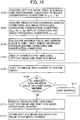
- step S1 a right-eye image and a left-eye image radiographed for a stereoscopic display and the radiographic conditions are acquired from the image server 32 or the like (S1).
- the radiographic conditions include the radiation source-image reception plane distance (SID) D, the irradiation angle of the radiation source (the rotation angle of the radiation source arm) ⁇ , the pressing thickness (the radiographic stand-pressing plate surface distance) l p , and the case thickness (the radiographic stand-image reception plane distance) l c .
- step S3 the maximum and minimum values of the first inter-image distance x m between the right-eye image and the left-eye image are calculated from the radiographic conditions.
- the maximum and minimum values are calculated using this range as the movable range in the depth direction (S3).
- the right-eye image and the left-eye image are often fixed to a position of 0°, a position of 4°, and the like. Accordingly, when the pressing thickness l p is determined, the maximum and minimum values of the first inter-image distance x m are determined.
- the maximum and minimum values of the first inter-image distance x m are calculated by the control unit 54 of the console 30 of the stereoscopic display apparatus 10. During the radiographing, the maximum and minimum values of the range allowing a stereoscopic display may be calculated in advance and the values along with the images may be stored.
- a stereoscopic display is performed in the image display area 22 of the display unit 12 (20) by the use of the right-eye image and the left-eye image in step S5 (S5).
- thumbnail images of the right-eye image and the left-eye image are displayed in the image different display area 26 and it is thus possible to confirm by what to shift both images for the stereoscopic display.
- step S7 the thumbnail images of the right-eye image and the left-eye image in the image difference display area 26 are shifted by the use of the cursor 24 on the display unit 12 (20) to change the depth of the stereoscopic display (S7).
- the shift distance between the right-eye image and the left-eye image is calculated from the shift distance of the thumbnail images and it is determined whether the first inter-image distance x m between the right-eye image and the left-eye image is in the above-mentioned range of the inter-image distance by the shift, that is, whether the first inter-image distance is out of the range between the maximum and minimum values of the first inter-image distance x m in step S9 (S9).
- step S11 When it is determined that the first inter-image distance x m between the right-eye image and the left-eye image is out of the range between the calculated maximum and minimum values, a warning is given in step S11 (S11).
- the alarm may be visual like a blink alarm or may be auditory like a sound.
- the thumbnail images may be limited so as not to depart from the range of the maximum and minimum values.
- step S13 When the first inter-image distance x m becomes a predetermined value by the shift of thumbnail images, at least one of the right-eye image and the left-eye image is shifted depending on the distance between the thumbnail images and the inter-image distance therebetween is used as x m after the shift, whereby the stereoscopic display is performed in step S13 (S13).
- An observer confirms the stereoscopic display after the change in depth and stores the right-eye image and the left-eye image after the change in depth (the right-eye image, the left-eye image, and the distance therebetween) so as to reproduce the stereoscopic display in step S15 (S15).
- the first embodiment of the stereoscopic display apparatus according to the present invention on the premise that the stereoscopic display apparatus 10 is observed at the observation position separated by a predetermined distance from the display unit 12 of the stereoscopic display apparatus 10 has been described hitherto.
- the stereoscopic display of the display unit 12 is necessarily observed at the observation position as in the first embodiment.
- the preferable conditions for the stereoscopic display vary depending on an observer's binocular distance to be described later.
- observation conditions conditions for observation: observation position and binocular distance to be described later
- display conditions an inter-pixel distance of the display apparatus
- image processing conditions an enlargement and reduction ratio of an image
- the configuration of the stereoscopic display apparatus according to the second embodiment of the present invention is the same as the stereoscopic display apparatus 10 according to the first embodiment shown in FIGS. 1 and 2 and thus description thereof will not be repeated.
- the second embodiment is different from the first embodiment, in that conditions for display (display conditions), conditions for processing image (image processing conditions), and conditions for observation (including an observer) (observation conditions) are considered in addition to the radiographic conditions when calculating the maximum and minimum values in shift of the right-eye image and the left-eye image.
- An enlargement ratio (enlargement and reduction ratio) based on the pixel size of the monitor (the display unit 12) can be considered as an example of the display conditions and a display magnification based on display software can be considered as an example of the image processing conditions.
- An observer's binocular distance, an observation distance (a distance between an observer and the display plane of the display unit 12 (with the second image display unit 18R disposed in front of the observer as a reference)), a right-left parallax on the display plane, an imaging plane distance (a distance to the imaging plane of a stereoscopic image), a binocular angle on the imaging plane, a binocular angle on the display plane, and the like can be considered as the observation conditions.
- the inter-bulb distance during radiographing is expressed by 2 ⁇ D ⁇ tan( ⁇ 1 /2) and the distance from the bulb to the pressing plate is expressed by D-1.
- the right-left parallax d' on the display plane is an appearing size of an image displayed on the monitor (the display unit 12) and the position gap x m of image data depends on the gap of imaging device. Therefore, it is necessary to match the size of the imaging device and the size of the display device with each other.
- d' is a magnitude which can be obtained by enlarging the original image and it is thus necessary to match d' with the distance at an enlargement ratio of 1 magnification (at the same magnification).
- the second inter-image distance (image shift distance) ⁇ d between a right-eye image and a left-eye image in the second embodiment is expressed as follows.
- Expression 18 ⁇ d d ⁇ m 1 ⁇ m 2 - x m
- the range of the second inter-image distance ⁇ d is expressed by the following expression.
- Expression 19 tan ⁇ 2 2 • D eye 2 + 4 ⁇ VD 2 m 1 ⁇ m 2 ⁇ 2 ⁇ VD + D eye • tan ⁇ 2 2 - 2 • D • tan ⁇ 1 2 • 1 p D - 1 p ⁇ ⁇ d ⁇ tan ⁇ 2 2 • D eye 2 + 4 ⁇ VD 2 m 1 ⁇ m 2 ⁇ 2 ⁇ VD + D eye • tan ⁇ 2 2 - 2 • D • tan ⁇ 1 2 • 1 c D - 1 c
- the stereoscopic display apparatus 10 calculates the inter-image distance between a right-eye image and a left-eye image in consideration of the conditions for radiographing and observation and performs a stereoscopic display on the basis of the inter-image distance, and thus can perform a stereoscopic display which can be observed more easily than in the first embodiment and which considers the situation of radiographing and the situation of observation.
- the radiographic conditions, the observation conditions, the display conditions, and the image processing conditions as well as the image data of the right-eye image and the left-eye image and the inter-image distance may be stored in the storage unit 58 of the console 30 and may be used again to refer to the stereoscopic display.
- the observation conditions vary depending on the purpose of the stereoscopic display or the observer's binocular distance and are thus stored in correlation with the purpose or the observer information.
- the inter-image distance may be corrected by the image processing unit 52, the control unit 54, and the display control unit 56 on the basis of another observer's observation conditions (mainly the binocular distance).
- a right-eye image and a left-eye image radiographed for a stereoscopic display and the radiographic conditions thereof are acquired from the image server 32 or the like in step S101 (S101).
- SID radiation source-image reception plane distance
- the pressing thickness the radiographic stand-pressing plate surface distance
- l c the case thickness
- step S102 an observer's binocular distance D eye , an observation distance VD, a right-left parallax d' on the display plane, an imaging plane distance x, a binocular angle ⁇ on the imaging plane, a binocular angle ⁇ on the display plane, and the like are input as the observation conditions through the use of the operation input unit 16. Predetermined values may be input in advance as the observation conditions. Similarly to the observation conditions, the conditions used depending on the screen size of the display unit 12 or the magnitude of the image data are acquired as the display conditions (the enlargement ratio m 1 based on the pixel size of the monitor) and the image processing conditions (the display magnification m 2 of display software) (S102).
- step S103 the maximum and minimum values of the second inter-image distance (image shift distance) ⁇ d between the right-eye image and the left-eye image are calculated from the radiographic conditions, the observation conditions, and the like.
- the second inter-image distance ⁇ d is calculated by Expression 17.
- the maximum and minimum values are calculated using this range as the movable range in the depth direction (S103).
- the right-eye image and the left-eye image are often fixed to a position of 0°, a position of 4°, and the like. Accordingly, when the pressing thickness l p is determined, the maximum and minimum values of the second inter-image distance ⁇ d are determined.
- the maximum and minimum values of the second inter-image distance ⁇ d are calculated by the control unit 54 of the console 30 of the stereoscopic display apparatus 10. During the radiographing, the maximum and minimum values of the range allowing a stereoscopic display may be calculated in advance and the values along with the images may be stored.
- a stereoscopic display is performed in the image display area 22 of the display unit 12 (20) by the use of the right-eye image and the left-eye image in step S105 (S105).
- thumbnail images of the right-eye image and the left-eye image are displayed in the image difference display area 26 and it is thus possible to confirm by what to shift both images for the stereoscopic display.
- step S107 the thumbnail images of the right-eye image and the left-eye image in the image difference display area 26 are shifted by the use of the cursor 24 on the display unit 12 (20) to change the depth of the stereoscopic display (S107).
- the shift distance between the right-eye image and the left-eye image is calculated from the shift distance of the thumbnail images and it is determined whether the second inter-image distance ⁇ d between the right-eye image and the left-eye image is in the above-mentioned range of the inter-image distance by the shift, that is, whether the second inter-image distance ⁇ d is out of the range between the maximum and minimum values of the second inter-image distance ⁇ d in step S109 (S109).
- step S111 When it is determined that the second inter-image distance ⁇ d between the right-eye image and the left-eye image is out of the range between the calculated maximum and minimum values, a warning is given in step S111 (S111) as in the first embodiment.
- the alarm may be visual like a blink alarm or may be auditory like a sound.
- the thumbnail images may be limited so as not to depart from the range of the maximum and minimum values.
- step S113 When the second inter-image distance ⁇ d becomes a predetermined value by the shift of thumbnail images, at least one of the right-eye image and the left-eye image is shifted depending on the distance between the thumbnail images and the inter-image distance therebetween is used as ⁇ d after the shift, whereby the stereoscopic display is performed in step S113 (S113).
- An observer confirms the stereoscopic display after the change in depth and stores the right-eye image and the left-eye image after the change in depth (image data of the right-eye image and the left-eye image, the radiographic conditions, the observation conditions, and the like) so as to reproduce the stereoscopic display in step S115 (S115).
- the second inter-image distance ⁇ d and the observation conditions are stored along with the image data of the right-eye image and the left-eye image. Accordingly, even when an observer is changed, it is possible to perform a desired stereoscopic display on th the basis of the stored image data of the right-eye image and the left-eye image by changing the observation conditions and re-calculating the second inter-image distance ⁇ d.
- the stereoscopic display apparatus considering the observation conditions, the display conditions, and the image processing conditions in addition to the radiographic conditions has been described.
- the inter-image distance (which is x m in the first embodiment and ⁇ d in the second embodiment and which includes the first inter-image distance x m and the second inter-image distance ⁇ d) is manually changed (by shifting the thumbnail images through the use of the cursor 24).
- the changing means may have an automatic control function and the inter-image distances x m and ⁇ d may be automatically changed by the console 30 on the basis of the radiographic conditions and the like (the observation conditions, the display conditions, and the image processing conditions in addition to the radiographic conditions in the second embodiment).
- the inter-image distances x m and ⁇ d may be changed so as to is the deepest in the depth direction without destroying the stereoscopic display on the basis of the pressing thickness l p and the irradiation angles ⁇ 1 and ⁇ 2 of the radiation source (the bulb oscillation angle ⁇ 1 ) and may be changed to the center of the controllable range so as for an operator to easily readjust the inter-image distances.
- the inter-image distances may be changed so as to be the shortest in the depth direction on the premise that the operator changes the inter-image distances.
- the changing means may have an automatic control function and thus the inter-image distances x m and ⁇ d may be automatically changed on the basis of the inter-image distances of another stereoscopic display stored in the image server 32 by the console 30.
- the inter-image distances x m and ⁇ d of the present stereoscopic display are determined on the basis of the inter-image distances of another stereoscopic display as a comparison target stored in the image server 32.
- Blanks of a right-eye image and a left-eye image generated when the inter-image distances are changed by the changing means may be painted with a predetermined color during the stereoscopic display.
- the blanks may be painted with black. By painting the blanks with black, it is possible to prevent erroneous diagnosis in radiographic image diagnosis and to cause an image area as a transmitted image to be visible well.
- the inter-image distances are changed by the changing means, it is preferable that it is stored what observer changes the inter-image distances by the use of what stereoscopic display apparatus (the display unit 12).
- the observation conditions binocular distance and observation distance
- the stereoscopic display on the basis of the inter-image distances (display conditions (enlargement and reduction ratio) and image processing conditions (display magnification)) different depending on the display apparatuses when the stereoscopic display apparatus is changed, it is possible to perform a stereoscopic display optimal for other observers only by fine adjustment.
- the stereoscopic display apparatus 10 employs a synthesis display system using polarized light and a half mirror, but the present invention is not limited to this system and may be applied to stereoscopic display apparatuses employing other display systems.
Landscapes
- Engineering & Computer Science (AREA)
- Life Sciences & Earth Sciences (AREA)
- Health & Medical Sciences (AREA)
- Physics & Mathematics (AREA)
- Multimedia (AREA)
- Signal Processing (AREA)
- Medical Informatics (AREA)
- Optics & Photonics (AREA)
- Nuclear Medicine, Radiotherapy & Molecular Imaging (AREA)
- Molecular Biology (AREA)
- High Energy & Nuclear Physics (AREA)
- Veterinary Medicine (AREA)
- Public Health (AREA)
- Pathology (AREA)
- Radiology & Medical Imaging (AREA)
- Biomedical Technology (AREA)
- Heart & Thoracic Surgery (AREA)
- Biophysics (AREA)
- Surgery (AREA)
- Animal Behavior & Ethology (AREA)
- General Health & Medical Sciences (AREA)
- Electromagnetism (AREA)
- General Physics & Mathematics (AREA)
- Human Computer Interaction (AREA)
- Apparatus For Radiation Diagnosis (AREA)
- Testing, Inspecting, Measuring Of Stereoscopic Televisions And Televisions (AREA)
- Stereoscopic And Panoramic Photography (AREA)
Applications Claiming Priority (2)
| Application Number | Priority Date | Filing Date | Title |
|---|---|---|---|
| JP2011079926 | 2011-03-31 | ||
| JP2011168616A JP2012213583A (ja) | 2011-03-31 | 2011-08-01 | 立体視表示装置 |
Publications (2)
| Publication Number | Publication Date |
|---|---|
| EP2506586A2 true EP2506586A2 (de) | 2012-10-03 |
| EP2506586A3 EP2506586A3 (de) | 2013-06-12 |
Family
ID=45688381
Family Applications (1)
| Application Number | Title | Priority Date | Filing Date |
|---|---|---|---|
| EP12157124.4A Withdrawn EP2506586A3 (de) | 2011-03-31 | 2012-02-27 | Stereoskopische Anzeigevorrichtung |
Country Status (4)
| Country | Link |
|---|---|
| US (1) | US20120249534A1 (de) |
| EP (1) | EP2506586A3 (de) |
| JP (1) | JP2012213583A (de) |
| CN (1) | CN102740099A (de) |
Families Citing this family (5)
| Publication number | Priority date | Publication date | Assignee | Title |
|---|---|---|---|---|
| CN104994787B (zh) * | 2013-02-14 | 2018-03-13 | 东芝医疗系统株式会社 | X射线诊断装置 |
| WO2015191768A1 (en) * | 2014-06-10 | 2015-12-17 | Bitanimate, Inc | Stereoscopic video zooming and foreground and background detection in a video |
| US10158847B2 (en) * | 2014-06-19 | 2018-12-18 | Vefxi Corporation | Real—time stereo 3D and autostereoscopic 3D video and image editing |
| JP7143092B2 (ja) * | 2018-03-12 | 2022-09-28 | ソニー・オリンパスメディカルソリューションズ株式会社 | 医療用画像処理装置、医療用観察装置、および画像処理方法 |
| JP7488037B2 (ja) * | 2018-10-24 | 2024-05-21 | キヤノンメディカルシステムズ株式会社 | 医用画像診断装置、医用画像診断方法、およびプログラム |
Citations (2)
| Publication number | Priority date | Publication date | Assignee | Title |
|---|---|---|---|---|
| JP3780217B2 (ja) | 2002-02-27 | 2006-05-31 | キヤノン株式会社 | 放射線撮影装置 |
| JP2010200787A (ja) | 2009-02-27 | 2010-09-16 | Fujifilm Corp | 放射線画像表示装置 |
Family Cites Families (10)
| Publication number | Priority date | Publication date | Assignee | Title |
|---|---|---|---|---|
| JPH0669449B2 (ja) * | 1989-10-30 | 1994-09-07 | 株式会社東芝 | ステレオ視観察のためのx線画像取得表示方法及びその装置 |
| US6031565A (en) * | 1993-06-18 | 2000-02-29 | Gte Internetworking Incorporated | Stereo radiography |
| JPH0779961A (ja) * | 1993-09-20 | 1995-03-28 | Hitachi Ltd | 透過像立体撮像表示方法およびその装置 |
| US6005607A (en) * | 1995-06-29 | 1999-12-21 | Matsushita Electric Industrial Co., Ltd. | Stereoscopic computer graphics image generating apparatus and stereoscopic TV apparatus |
| WO2004093467A1 (ja) * | 2003-04-17 | 2004-10-28 | Sharp Kabushiki Kaisha | 3次元画像作成装置、3次元画像再生装置、3次元画像処理装置、3次元画像処理プログラムおよびそのプログラムを記録した記録媒体 |
| JP4652727B2 (ja) * | 2004-06-14 | 2011-03-16 | キヤノン株式会社 | 立体画像生成システムおよびその制御方法 |
| EP1659511A1 (de) * | 2004-11-18 | 2006-05-24 | Cedara Software Corp. | Bildarchivierungssystem und Verfahren zum Handhaben von neuen und bereits bestehenden Archiven |
| JP4649219B2 (ja) * | 2005-02-01 | 2011-03-09 | キヤノン株式会社 | 立体画像生成装置 |
| JP2010187916A (ja) * | 2009-02-18 | 2010-09-02 | Fujifilm Corp | 画像処理装置、画像処理システム及びプログラム |
| JP5266126B2 (ja) * | 2009-03-31 | 2013-08-21 | 富士フイルム株式会社 | 画像表示装置および方法並びにプログラム |
-
2011
- 2011-08-01 JP JP2011168616A patent/JP2012213583A/ja not_active Withdrawn
-
2012
- 2012-02-27 EP EP12157124.4A patent/EP2506586A3/de not_active Withdrawn
- 2012-02-29 US US13/408,865 patent/US20120249534A1/en not_active Abandoned
- 2012-02-29 CN CN2012100506283A patent/CN102740099A/zh active Pending
Patent Citations (2)
| Publication number | Priority date | Publication date | Assignee | Title |
|---|---|---|---|---|
| JP3780217B2 (ja) | 2002-02-27 | 2006-05-31 | キヤノン株式会社 | 放射線撮影装置 |
| JP2010200787A (ja) | 2009-02-27 | 2010-09-16 | Fujifilm Corp | 放射線画像表示装置 |
Also Published As
| Publication number | Publication date |
|---|---|
| JP2012213583A (ja) | 2012-11-08 |
| CN102740099A (zh) | 2012-10-17 |
| EP2506586A3 (de) | 2013-06-12 |
| US20120249534A1 (en) | 2012-10-04 |
Similar Documents
| Publication | Publication Date | Title |
|---|---|---|
| EP2536156B1 (de) | Bildverarbeitungssystem, Bildverarbeitungsvorrichtung und Bildverarbeitungsverfahren | |
| JP5284731B2 (ja) | 立体画像撮影表示システム | |
| JP5486437B2 (ja) | 立体視画像表示方法および装置 | |
| US20120327080A1 (en) | Image processing system, terminal device, and image processing method | |
| EP2506586A2 (de) | Stereoskopische Anzeigevorrichtung | |
| US20130300737A1 (en) | Stereoscopic image generating apparatus, stereoscopic image generating method, and stereoscopic image generating program | |
| US20120249533A1 (en) | Stereoscopic display apparatus | |
| US20110218425A1 (en) | Medical image generating apparatus, medical image display apparatus, medical image generating method and program | |
| WO2012081244A1 (ja) | 表示装置 | |
| US9020219B2 (en) | Medical image processing apparatus | |
| JP2012244420A (ja) | 画像処理システム、装置及び方法 | |
| JP2012110645A (ja) | 立体視画像表示装置および立体視画像表示方法 | |
| US20120025088A1 (en) | Radiological image radiographing and displaying method and apparatus | |
| JP2012213484A (ja) | 立体視表示装置 | |
| JP2012115380A (ja) | 立体視画像取得方法および装置 | |
| WO2012056695A1 (ja) | 立体視画像表示装置および方法並びにプログラム | |
| JP2012068610A (ja) | 立体視画像表示装置、放射線画像撮影表示システムおよび立体視画像表示方法 | |
| JP5835980B2 (ja) | 画像処理システム、装置、方法及び医用画像診断装置 | |
| WO2012066753A1 (ja) | 立体視画像表示方法および装置 | |
| WO2012102022A1 (ja) | 立体視画像表示方法、並びに、立体視画像表示制御装置およびプログラム | |
| JP2012073996A (ja) | 画像配信装置および方法 | |
| JP2012095274A (ja) | 立体視画像表示装置および立体視画像表示方法 | |
| JP2012075001A (ja) | 立体視画像表示方法および立体視画像表示装置 | |
| WO2012132320A1 (ja) | 立体視画像表示装置および立体視画像表示方法 | |
| WO2012043480A1 (ja) | 立体視画像表示方法および立体視画像表示装置 |
Legal Events
| Date | Code | Title | Description |
|---|---|---|---|
| PUAI | Public reference made under article 153(3) epc to a published international application that has entered the european phase |
Free format text: ORIGINAL CODE: 0009012 |
|
| AK | Designated contracting states |
Kind code of ref document: A2 Designated state(s): AL AT BE BG CH CY CZ DE DK EE ES FI FR GB GR HR HU IE IS IT LI LT LU LV MC MK MT NL NO PL PT RO RS SE SI SK SM TR |
|
| AX | Request for extension of the european patent |
Extension state: BA ME |
|
| PUAL | Search report despatched |
Free format text: ORIGINAL CODE: 0009013 |
|
| AK | Designated contracting states |
Kind code of ref document: A3 Designated state(s): AL AT BE BG CH CY CZ DE DK EE ES FI FR GB GR HR HU IE IS IT LI LT LU LV MC MK MT NL NO PL PT RO RS SE SI SK SM TR |
|
| AX | Request for extension of the european patent |
Extension state: BA ME |
|
| RIC1 | Information provided on ipc code assigned before grant |
Ipc: H04N 13/04 20060101AFI20130507BHEP Ipc: A61B 6/02 20060101ALI20130507BHEP Ipc: H04N 13/02 20060101ALI20130507BHEP Ipc: H04N 13/00 20060101ALI20130507BHEP |
|
| STAA | Information on the status of an ep patent application or granted ep patent |
Free format text: STATUS: THE APPLICATION IS DEEMED TO BE WITHDRAWN |
|
| 18D | Application deemed to be withdrawn |
Effective date: 20131213 |