EP2506888B1 - Coeur artificiel total - Google Patents
Coeur artificiel total Download PDFInfo
- Publication number
- EP2506888B1 EP2506888B1 EP10835219.6A EP10835219A EP2506888B1 EP 2506888 B1 EP2506888 B1 EP 2506888B1 EP 10835219 A EP10835219 A EP 10835219A EP 2506888 B1 EP2506888 B1 EP 2506888B1
- Authority
- EP
- European Patent Office
- Prior art keywords
- rotor
- blood
- vascular
- artificial heart
- connector
- Prior art date
- Legal status (The legal status is an assumption and is not a legal conclusion. Google has not performed a legal analysis and makes no representation as to the accuracy of the status listed.)
- Active
Links
Images



Classifications
-
- A—HUMAN NECESSITIES
- A61—MEDICAL OR VETERINARY SCIENCE; HYGIENE
- A61M—DEVICES FOR INTRODUCING MEDIA INTO, OR ONTO, THE BODY; DEVICES FOR TRANSDUCING BODY MEDIA OR FOR TAKING MEDIA FROM THE BODY; DEVICES FOR PRODUCING OR ENDING SLEEP OR STUPOR
- A61M60/00—Blood pumps; Devices for mechanical circulatory actuation; Balloon pumps for circulatory assistance
- A61M60/40—Details relating to driving
- A61M60/403—Details relating to driving for non-positive displacement blood pumps
- A61M60/419—Details relating to driving for non-positive displacement blood pumps the force acting on the blood contacting member being permanent magnetic, e.g. from a rotating magnetic coupling between driving and driven magnets
-
- A—HUMAN NECESSITIES
- A61—MEDICAL OR VETERINARY SCIENCE; HYGIENE
- A61M—DEVICES FOR INTRODUCING MEDIA INTO, OR ONTO, THE BODY; DEVICES FOR TRANSDUCING BODY MEDIA OR FOR TAKING MEDIA FROM THE BODY; DEVICES FOR PRODUCING OR ENDING SLEEP OR STUPOR
- A61M60/00—Blood pumps; Devices for mechanical circulatory actuation; Balloon pumps for circulatory assistance
- A61M60/10—Location thereof with respect to the patient's body
- A61M60/122—Implantable pumps or pumping devices, i.e. the blood being pumped inside the patient's body
- A61M60/196—Implantable pumps or pumping devices, i.e. the blood being pumped inside the patient's body replacing the entire heart, e.g. total artificial hearts [TAH]
-
- A—HUMAN NECESSITIES
- A61—MEDICAL OR VETERINARY SCIENCE; HYGIENE
- A61M—DEVICES FOR INTRODUCING MEDIA INTO, OR ONTO, THE BODY; DEVICES FOR TRANSDUCING BODY MEDIA OR FOR TAKING MEDIA FROM THE BODY; DEVICES FOR PRODUCING OR ENDING SLEEP OR STUPOR
- A61M60/00—Blood pumps; Devices for mechanical circulatory actuation; Balloon pumps for circulatory assistance
- A61M60/10—Location thereof with respect to the patient's body
- A61M60/122—Implantable pumps or pumping devices, i.e. the blood being pumped inside the patient's body
- A61M60/126—Implantable pumps or pumping devices, i.e. the blood being pumped inside the patient's body implantable via, into, inside, in line, branching on, or around a blood vessel
- A61M60/148—Implantable pumps or pumping devices, i.e. the blood being pumped inside the patient's body implantable via, into, inside, in line, branching on, or around a blood vessel in line with a blood vessel using resection or like techniques, e.g. permanent endovascular heart assist devices
-
- A—HUMAN NECESSITIES
- A61—MEDICAL OR VETERINARY SCIENCE; HYGIENE
- A61M—DEVICES FOR INTRODUCING MEDIA INTO, OR ONTO, THE BODY; DEVICES FOR TRANSDUCING BODY MEDIA OR FOR TAKING MEDIA FROM THE BODY; DEVICES FOR PRODUCING OR ENDING SLEEP OR STUPOR
- A61M60/00—Blood pumps; Devices for mechanical circulatory actuation; Balloon pumps for circulatory assistance
- A61M60/20—Type thereof
- A61M60/205—Non-positive displacement blood pumps
- A61M60/216—Non-positive displacement blood pumps including a rotating member acting on the blood, e.g. impeller
- A61M60/237—Non-positive displacement blood pumps including a rotating member acting on the blood, e.g. impeller the blood flow through the rotating member having mainly axial components, e.g. axial flow pumps
- A61M60/242—Non-positive displacement blood pumps including a rotating member acting on the blood, e.g. impeller the blood flow through the rotating member having mainly axial components, e.g. axial flow pumps with the outlet substantially perpendicular to the axis of rotation
-
- A—HUMAN NECESSITIES
- A61—MEDICAL OR VETERINARY SCIENCE; HYGIENE
- A61M—DEVICES FOR INTRODUCING MEDIA INTO, OR ONTO, THE BODY; DEVICES FOR TRANSDUCING BODY MEDIA OR FOR TAKING MEDIA FROM THE BODY; DEVICES FOR PRODUCING OR ENDING SLEEP OR STUPOR
- A61M60/00—Blood pumps; Devices for mechanical circulatory actuation; Balloon pumps for circulatory assistance
- A61M60/40—Details relating to driving
- A61M60/403—Details relating to driving for non-positive displacement blood pumps
- A61M60/422—Details relating to driving for non-positive displacement blood pumps the force acting on the blood contacting member being electromagnetic, e.g. using canned motor pumps
-
- A—HUMAN NECESSITIES
- A61—MEDICAL OR VETERINARY SCIENCE; HYGIENE
- A61M—DEVICES FOR INTRODUCING MEDIA INTO, OR ONTO, THE BODY; DEVICES FOR TRANSDUCING BODY MEDIA OR FOR TAKING MEDIA FROM THE BODY; DEVICES FOR PRODUCING OR ENDING SLEEP OR STUPOR
- A61M60/00—Blood pumps; Devices for mechanical circulatory actuation; Balloon pumps for circulatory assistance
- A61M60/50—Details relating to control
- A61M60/508—Electronic control means, e.g. for feedback regulation
- A61M60/515—Regulation using real-time patient data
-
- A—HUMAN NECESSITIES
- A61—MEDICAL OR VETERINARY SCIENCE; HYGIENE
- A61M—DEVICES FOR INTRODUCING MEDIA INTO, OR ONTO, THE BODY; DEVICES FOR TRANSDUCING BODY MEDIA OR FOR TAKING MEDIA FROM THE BODY; DEVICES FOR PRODUCING OR ENDING SLEEP OR STUPOR
- A61M60/00—Blood pumps; Devices for mechanical circulatory actuation; Balloon pumps for circulatory assistance
- A61M60/80—Constructional details other than related to driving
- A61M60/802—Constructional details other than related to driving of non-positive displacement blood pumps
- A61M60/818—Bearings
- A61M60/824—Hydrodynamic or fluid film bearings
-
- A—HUMAN NECESSITIES
- A61—MEDICAL OR VETERINARY SCIENCE; HYGIENE
- A61M—DEVICES FOR INTRODUCING MEDIA INTO, OR ONTO, THE BODY; DEVICES FOR TRANSDUCING BODY MEDIA OR FOR TAKING MEDIA FROM THE BODY; DEVICES FOR PRODUCING OR ENDING SLEEP OR STUPOR
- A61M60/00—Blood pumps; Devices for mechanical circulatory actuation; Balloon pumps for circulatory assistance
- A61M60/80—Constructional details other than related to driving
- A61M60/802—Constructional details other than related to driving of non-positive displacement blood pumps
- A61M60/818—Bearings
- A61M60/825—Contact bearings, e.g. ball-and-cup or pivot bearings
-
- A—HUMAN NECESSITIES
- A61—MEDICAL OR VETERINARY SCIENCE; HYGIENE
- A61M—DEVICES FOR INTRODUCING MEDIA INTO, OR ONTO, THE BODY; DEVICES FOR TRANSDUCING BODY MEDIA OR FOR TAKING MEDIA FROM THE BODY; DEVICES FOR PRODUCING OR ENDING SLEEP OR STUPOR
- A61M2205/00—General characteristics of the apparatus
- A61M2205/33—Controlling, regulating or measuring
- A61M2205/3331—Pressure; Flow
- A61M2205/3334—Measuring or controlling the flow rate
Definitions
- This invention pertains generally to cardiovascular implants, and more particularly to devices that completely replace a failing heart to provide blood flow to the pulmonary and systemic circulation.
- Congestive heart failure is a major, rapidly growing public health problem that results in hundreds of thousands of deaths annually.
- Patients with bi-ventricular end stage heart failure who are refractory to medications, surgical intervention and resynchronizer pacing are best treated with cardiac transplantation.
- donor hearts are limited to about 2,000 per year in the United States and, consequently, there is a large unmet need for approximately 75,000 patients who would benefit from cardiac transplantation, but for whom no donor heart is available.
- a mechanical total artificial heart (TAH) could replace a failing heart and offer improved survival and functional capability comparable to cardiac transplantation.
- LVAD left ventricular assist devices
- the HeartMateTM is a positive displacement pump used as a bridge to cardiac transplantation and destination therapy in patients with severe congestive heart failure.
- the HeartMateTM II a rotary pump, has received PMA approval for bridge to transplantation.
- LVAD's such as these are gaining clinical acceptance, but development of total artificial hearts (TAH) has not kept pace, particularly for permanent assistance without intention to bridge to cardiac transplantation. Two total artificial hearts are clinically available on a very limited basis in the United States.
- the SynCardia TAH by CardioWest is implanted in the chest and is powered by an external pneumatic driver via air hoses which penetrate the chest. It has been approved for temporary use as a bridge to transplantation in patients who cannot be supported with an LVAD alone and has demonstrated clinical efficacy in several hundred patients.
- the AbiocorTM TAH by Abiomed, Inc. is intended for permanent use and is totally implantable. It has a self-contained electric motor and receives power by means of transcutaneous power transmission, but has been approved by FDA only for compassionate use.
- Each of the CardioWest and Abiocor devices employ two separate pumps to replace the right and left ventricles, respectively. These pumps are positive displacement pumps with two valves per pump (total of four valves) to ensure unidirectional flow of blood.
- the anatomical compatibility of these devices has limited their use to larger patients, since positive displacement pumps are inherently large.
- Rotary blood pumps based on centrifugal or axial flow hydraulics have proven to be safe and durable pumps for use as left ventricular devices and could offer many advantages over positive displacement pumps if they were adapted for use as a total artificial heart. Most importantly, rotary blood pumps would be much smaller than existing pulsatile TAH's and would not require artificial valves or a means for volume compensation or venting. In addition, rotary blood pumps, such as the HeartMate II, have proven durability for many years.
- a total artificial heart based on a single rotary impeller would offer significant advantage in reduced size, simplicity and cost over existing devices intended for complete replacement of the heart.
- WO 2006/053384 describes a fluid pump including a housing defining a cavity having a cavity axis.
- a housing has two fluid inlets and outlets and a set of coils for generating a magnetic field.
- An impeller is positioned in the cavity, the impeller having two sets of vanes each set of vanes being adapted to urge fluid from a respective inlet to a respective outlet.
- a drive system is provided for rotating the impeller about the cavity axis and controlling an axial position of the impeller in the direction parallel to the cavity axis to thereby control the relative flows from each inlet to each respective outlet.
- US 2007/0253842 describes a two stage rotodynamic blood pump including a housing, a status supported in the housing and a rotor assembly.
- the rotor assembly includes a rotor supported in the housing for rotation relative to the stator.
- the rotor assembly also includes a first impeller operatively coupled to a first axial end of the rotor for rotation with the rotor about the axis.
- the rotor assembly further includes a second impeller operatively coupled to a second axial end of the rotor opposite the first end for rotation with the rotor about the axis.
- US 5,674,281 describes an artificial heart assembly which may be a total artificial heart or a ventricular assisted vice.
- the assembly has a blood inlet conduit, a blood outlet conduit, a pumping mechanism for pumping blood from the blood inlet conduit to the blood outlet conduit and means for reversibly driving the pumping mechanism in an opposite direction over a stroke having a length defined by a pair of endpoints.
- a total artificial heart employing a single impeller that is capable of providing circulation to both the pulmonary (right) and systemic (left) circulation.
- a rotor has an impeller mounted on a hollow shaft which contains magnets that react with electrical coils in a housing to produce rotary motion for pumping and axial translation within the housing to shuttle flow between the right and left circulation. The flow produced is inherently pulsatile.
- the present disclosure provides a total artificial heart capable of completely supporting the pulmonary and systemic circulation of the body with a rotary blood pump utilizing only one impeller.
- One aspect of the present disclosure provides a device comprising a rotary pump housing having a bore surrounded by a motor stator.
- Four connectors of the housing have apertures/channels that are in continuity with the bore and provide inflow and outflow for the right and left circulation.
- a rotor consists of a hollow shaft on which is mounted an impeller. Motor rotor magnets are located in the wall of the hollow shaft. During operation the rotor rotates within the housing and is capable of shuttling axially within the housing.
- the rotor is placed in the bore of a pump housing. Electrical coils surrounding the bore interact with the magnets in the rotor to produce rotary motion to pump fluid and axial motion to alternately pump blood between the pulmonary and systemic circulation.
- the inflow to the impeller can be provided from either end of the hollow shaft.
- the rotor also acts as shuttle valve by translating along the axis of the pump housing and alternately exposing and covering the ports of the housing to provide flow to the right and left heart.
- a motor stator concentric to the bore of the housing surrounds the motor rotor magnet in the hollow shaft. Current in the stator windings interacts with the magnetic field to produce torque and rotation of the rotor, thereby turning the impeller.
- the outlet of the impeller is alternately directed to the right and left circulation via the arterial ports in the housing.
- the bore of the rotor receives blood from the right and left atria through the atrial ports.
- Balance of right and left flow can be achieved by adjusting the duty cycle or dwell time of the right versus the left side. Speed could also be simultaneously adjusted to provide additional control. Since the rotor is alternately pumping to the right and left side, the flow will be inherently pulsatile.
- Radial support of the rotor will be provided by the action of a hydrodynamic bearing between the surface of the housing bore and the outer surface of the rotor wherein blood will be the hydrodynamic fluid. Internal pressure gradients will provide leakage flow within the journal bearing clearances to prevent stagnation and thrombus formation. Axial constraint of the rotor will be a combination of a passive axial magnetic bearing and hydrodynamic thrust bearings.
- Connections to the vascular system will be accomplished with a combination of prosthetic arterial grafts and synthetic atrial cuffs.
- Power can be provided by means of a percutaneous wire or transcutaneous power transmission. Measurements of flow and or pressure will be used to control the duty cycle and dwell time of the rotor in order to balance the flow between the right and left sides of the circulation.
- An aspect of the disclosure is total artificial heart (TAH) employing a single impeller that is capable of providing circulation to both the pulmonary (right) and systemic (left) circulation.
- TAH total artificial heart
- the total artificial heart comprises a rotor having an impeller mounted on a hollow shaft which contains magnets that react with electrical coils in a housing to produce rotary motion for pumping and axial translation within the housing to shuttle flow between the right and left circulation.
- the total artificial heart comprises a rotary pump housing having a bore surrounded by a motor stator the housing having four connectors that are in continuity with the bore and provide inflow and outflow for the right and left circulation.
- the rotor generally comprises a hollow shaft on which is mounted an impeller; and wherein motor rotor magnets are located in a wall of the hollow shaft. During operation, the rotor rotates within the housing and is capable of shuttling axially within the housing.
- a rotor is placed in a bore of a pump housing; with a plurality of electrical coils surrounding the bore and which interact with magnets in the rotor to produce rotary motion to pump fluid and axial motion to alternately pump blood between pulmonary and systemic circulation.
- FIG. 1 illustrates an exterior view of a total artificial heart (TAH) 10 in accordance with the present invention.
- TAH 10 comprises a pump housing 12 having a body 14 and four vascular connectors for accessing the circulatory system.
- the TAH 10 is shown and illustrated in the description below for replacement of the left and right ventricles of the heart, while connecting for input from both the systemic venous circulation and the pulmonary venous circulation via the right and left atria (not shown).
- the venous and arterial blood input into the TAH 10 may be from any location along the venous or arterial circulatory systems.
- venous blood from the right atrium is directed into the TAH 10 via channel/aperture 30 of the RA connector 20.
- Oxygenated blood from the left atrium (LA) is directed into the TAH 10 via channel 34 of the LA connector 24.
- Venous blood is delivered to the pulmonary artery (PA) via channel 32 the PA connector 22.
- Arterial blood is delivered to the aorta (AO) via channel 36 of the AO connector 26.
- PA pulmonary artery
- AO aorta
- Prosthetic conduits such as arterial grafts, synthetic atrial cuffs, or the like, may be used to couple the connectors 20, 22, 24, and 26 to respective anatomical features the vascular system.
- Connectors 20, 22, 24, and 26 comprise cylindrical outer surfaces that are sized to provide purchase for an internal wall (not shown) of the lumen (or prosthetic conduit) to be connected with, and additional clamping means (not shown) may be used to seal the lumen with respect to the corresponding connector.
- the displaced volume of the TAH 10 is preferably small enough such that the cavity left by removal of the native heart will be sufficient to accommodate the device. Ideally, TAH 10 will have a volume of less than 150 cc.
- controller 100 Power, control, and sensing feedback for the pump are provided via controller 100 and lead 102.
- the components of the controller may be external to the patient, or subcutaneous.
- the controller 100 may comprise a processor and battery power source that are completely implanted within the body, such that the battery is recharged via transcutaneous energy transmission (TET) through the skin.
- TET transcutaneous energy transmission
- the lead bundle 102 may lead through the skin to an external controller 100 and power supply.
- one or more components providing power, control or sensing are a combination of both internal and external devices.
- TAH 10 comprises a pump housing assembly 12 having a housing 14 configured to suspend a moveable rotor assembly 60 within inner chamber 16.
- the rotor assembly 60 comprises a rotor shaft 74 coupled to impeller body 82, which includes an impeller 66 comprising a plurality of radial slots that are in communication with a central channel 84 of the rotor assembly 60.
- the central channel 84 comprises a bore that passes through the entirety of the impeller assembly 60 from left inlet 62 at the left end 86 to right inlet 64 at right end 88.
- the bore 84 serves to channel blood into the hollow rotor 60 to the impeller 66.
- the impeller assembly 60 is configured to be magnetically driven to rotate inside chamber 16 of the housing assembly 12.
- the rotor shaft 74 of the impeller assembly 60 comprises a cylindrical rotor magnet 70 surrounded by a backiron 72 are positioned within the wall of the rotor shaft 74.
- the bore 16 of pump housing 14 comprises a stepped cylindrical channel in communication with input channels 30, 34 and output channels 32 and 36.
- the bore 16 comprises a first cylindrical inner surface 40 configured to interface with the cylindrical outer surface 76 of the rotor shaft 74, and a second inner cylindrical surface 42 configured to interface with the outer surface 80 of the impeller body 82.
- the left end 52 of the housing 14 comprises a cap 95 (see FIGS. 5 and 6 ) that may be detached from the housing 14 to allow insertion of the rotor 60. Cap 95 may be threaded into the housing 14, or may be attached by other means, such as welding, clamping, or the like.
- Housing 14 comprises an annular motor stator 46 that surrounds the bore 16 at inner surface 40 such that the motor stator 46 and is axially aligned with the rotor magnet 70 when the rotor assembly 60 is positioned within cavity 16.
- the motor stator 46 is concentric to the bore 16 of the housing and surrounds the motor rotor 60 magnet when positioned in the bore 16.
- Current in the stator 46 windings generates a magnetic field to interact with the rotor magnet 70 to produce torque and rotation of the rotor 60 about axis 85, thereby turning the impeller 66 to induce fluid flow.
- the rotor assembly may comprise a constant outer diameter across its length (not shown).
- the inside diameter of the internal chamber 16 would also be constant.
- Rotor assembly 60 also comprises an annular solenoid magnet 68 disposed within the wall of the impeller body 82.
- a solenoid coil 48 is disposed within the housing 14 to surround the housing bore 16 at surface 42, and is located to be proximate to the solenoid magnet 68 in the impeller body 82 when the rotor assembly 60 is positioned within cavity 16.
- FIGS. 3 and 4 illustrate a cutaway view of the pump assembly 10 rotor assembly 60 is positioned within cavity 16 of the housing assembly 12.
- the interaction between an electric current supplied to the motor stator 46 and the rotor magnet 70 produces rotary motion in the rotor 60 and hence, the impeller 66.
- the rotary motion of the impeller 66 imparts kinetic energy to the blood and creates pressurized flow to either the pulmonary artery (PA) or aorta (AO) while drawing blood from the RA and LA, respectively.
- PA pulmonary artery
- AO aorta
- a hydrodynamic journal bearing action is created in bearing clearance 56 between one or more of the inner surfaces 42, 44 of the housing bore 16 and the outer surfaces 76, 80 of the rotor shaft 74 and impeller body 82.
- the diameter inner surfaces 42, 44 of the housing bore are generally in the range of 0.002 in.-0.020 in. (0.0508 mm - 0.508 mm) and preferably within the range of 0.004 in.- 0.008 in. (0.1016 mm - 0.2032 mm) larger than the diameters of the outer surfaces 76, 80 of the rotor shaft 74 and impeller body 82, respectively. Accordingly, the gap/clearance 56 shown in FIG. 4 is exaggerated for clarity.
- the hydrodynamic bearing supports the rotor assembly 60 radially within the housing.
- the bearing clearance 56 also serves as a leak path to allow the flow FL of blood through the clearance to remove heat and minimize the risk of clotting.
- the radial gap between surface 42 of the housing and surface 82 of the of the impeller body may be sufficiently small (e.g. 0.002 in (0.0508 mm)) to form a hydrodynamic bearing, while the rotor shaft outer surface 76 may have a significantly larger gap (e.g. 0.020 in (0.508 mm) or more) that is not a hydrodynamic journal bearing, and vice versa.
- At least one hydrodynamic thrust bearing on either end of the rotor provides axial support for the rotor. Additional axial support is provided by the passive magnetic attraction between the motor stator 46 and the rotor magnet 70.
- the rotor assembly 60 is configured to also act as a shuttle valve by translating along the axis 85 of the pump housing 14 and alternately exposing and covering the ports 30, 32, 34, and 36 of the housing 14 to provide flow to the right and left heart. Accordingly, the rotor assembly 60 is configured to have two configurations to alternate flow between the systemic and pulmonary circulatory systems. As the rotor assembly 60 translates axially along axis 85, the outlet of the impeller 66 is alternately directed to the right and left circulation via the arterial ports 32, 36 in the housing. Likewise, the central channel 84 of the rotor 60 receives blood from the right and left atria through the atrial ports 30, 34.
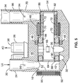
- FIG. 5 illustrates the system 10 in a first configuration (systemic circulation) that draws saturated blood from the left atrium (LA) and pumps it to the aorta (AO).
- the right side 86 of the rotor assembly 60 is positioned to the right side 54 of the pump housing 14 by the action of electrical current in solenoid coils 48, 92 acting on solenoid magnets 90, 68.
- Access to the input chamber 30 of the RA connector 20 (and right atrium connector 98) and output chamber 32 of the PA connector 22 are blocked by the solid surfaces 76, 80 of the rotor shaft 74 and impeller body 82 respectively.
- blood enters the input 34 of the LA connector 24, passes through inlet 64 of the rotor 60 and into the rotor central channel 84.
- the blood exits through the impeller 66 and into the output chamber 36 of the AO connector 26 into the aorta.
- FIG. 6 illustrates the system 10 in a second configuration (pulmonary circulation) that draws desaturated blood from the right atrium (RA) and pumps it to the pulmonary artery (PA). Then the direction of the current in solenoid coils 92 and 48 is reversed, the magnetic field acts on the poles of the solenoid magnets 68, 90 to push the rotor axially along axis 85 of bore 16 in the opposite direction, translating the left end 88 of the rotor 60 to abut to the left end 52 of the chamber 16. In this position, the input channel 34 of the LA connector 24 and the output channel 36 of the AO connector 26 are blocked by the solid surfaces 76, 80 of the rotor shaft 74 and impeller body 82 respectively. In this rotor position, blood from the RA enters input 30 of the RA connector 20, passes through inlet 62 of the rotor 60, flows through central channel 84 and out the impeller 66 and into the output channel 32 of the PA connector 22 to the PA.
- RA right atrium
- PA
- solenoid 92 may be configured to generate an alternating attractive and repulsive force on magnet 90 to singly drive the axial shuttling motion of the rotor assembly 60.
- a biasing member e.g. mechanical spring, magnetic spring, or the like- not shown
- the solenoid 92 acts to alternate between an "on” and “off” mode that drives the axial position of the rotor 60 against the biasing force applied by the biasing member.
- Balancing of the flow between the pulmonary and systemic circulation is adjusted by controlling the dwell time or duty cycle of the impeller as it moves, alternately, back and forth in the pump housing.
- controller 100 for driving the pump 10 may be based on sensorless commutation, which obviates the need for brushes, shaft seals and optical sensors.
- the control of flow balance between the pulmonary and systemic circulation may be supported via feedback from one or more sensors (e.g. sensors 94 and 96 illustrated in FIG. 5 ), with closed loop logic to insure that physiologic pressures are maintained in the atria.
- Direct measurement of blood flow may be performed with ultrasonic transducers 94 and 96 disposed in atria chambers 30, 32 that use the Doppler affect to measure velocity across a known cross sectional area (e.g. the diameter of the atrial chambers 30, 32).
- Signals from the transducers 94 and 96 are fed to controller 100, where they are processes with an algorithm that compares the right and left flows and adjust the dwell times to compensate for any disparity in flow.
- velocity measuring technologies such as hot wire anemometry or pitot tube, may also be adapted within the pump.
- pressures of the atria could be measured and these signals used to determine the ratio of the dwell time of the impeller 60 between the pulmonary and systemic circulation.
- the dwell time on the pulmonary outlet 32 of the pump could be decreased, or the dwell time on the systemic outlet 36 increased. In either case, the ratio of the dwell time systemic/pulmonary would increase.
- Indirect measurements of atrial pressure can be accomplished by measuring the diameter of the atria or stretching of the atrial walls. Miniature ultrasonic transducers can be used for these measurements, and are stable when implanted.
- the pump 10 By using measured parameters such as pressure, flow, flow velocity or oxygen saturation, it is possible for the pump 10 to adapt to any patient during a wide range of conditions at any time.
- radial suspension of the rotor could be achieved with magnetic bearings, either passive or actively controlled.
- active magnetic control in the axial direction could be adapted to this concept and numerous form factors for the outer surface and geometry of vascular connectors could be implemented to optimize anatomical placement.
Landscapes
- Health & Medical Sciences (AREA)
- Engineering & Computer Science (AREA)
- Heart & Thoracic Surgery (AREA)
- Cardiology (AREA)
- Life Sciences & Earth Sciences (AREA)
- Public Health (AREA)
- Biomedical Technology (AREA)
- Hematology (AREA)
- Mechanical Engineering (AREA)
- Animal Behavior & Ethology (AREA)
- General Health & Medical Sciences (AREA)
- Anesthesiology (AREA)
- Veterinary Medicine (AREA)
- Medical Informatics (AREA)
- Physics & Mathematics (AREA)
- Fluid Mechanics (AREA)
- Vascular Medicine (AREA)
- External Artificial Organs (AREA)
Claims (13)
- Cœur artificiel total, comprenant :un boîtier de pompe (12) comprenant des premier, deuxième, troisième et quatrième connecteurs vasculaires (20, 22, 24, 26) ;dans lequel chacun des connecteurs vasculaires (20, 22, 24, 26) est en communication fluidique avec un alésage au sein du boîtier ; etun rotor (60) configuré pour être logé de manière rotative au sein de l'alésage ;le rotor (60) ayant une roue (66) configurée pour pomper le sang vers et depuis les connecteurs vasculaires (20, 22, 24, 26) lors de la rotation du rotor autour d'un axe central de l'alésage ;dans lequel le rotor est sensible aux forces magnétiques conférées par ledit boîtier de pompe pour entraîner la rotation du rotor ;dans lequel le rotor (60) est configuré pour effectuer une translation le long de l'axe central de l'alésage d'une première position à une deuxième position ;dans lequel, dans la première position, le rotor (60) est configuré pour soutirer un premier volume de sang depuis le premier connecteur vasculaire (24) et pomper le premier volume de sang jusque dans le deuxième connecteur vasculaire (26) tout en bloquant l'écoulement vers et depuis les troisième et quatrième connecteurs vasculaires (20 et 22) ; etdans lequel, dans la deuxième position, le rotor (60) est configuré pour soutirer un deuxième volume de sang depuis le troisième connecteur vasculaire (20) et pomper le deuxième volume de sang jusque dans le quatrième connecteur vasculaire (22) tout en bloquant l'écoulement vers et depuis les premier et deuxième connecteurs vasculaires (24 et 26).
- Cœur artificiel total tel que récité dans la revendication 1 :dans lequel le premier connecteur vasculaire (24) comprend un connecteur (30) d'oreillette gauche, LA, le deuxième connecteur vasculaire (26) comprend un connecteur d'aorte, AO, le troisième connecteur vasculaire (20) comprend un connecteur d'oreillette droite, RA, le quatrième connecteur vasculaire (22) comprend un connecteur d'artère pulmonaire, PA ; etdans lequel le rotor (60), lors de l'utilisation, se déplace entre la première position et la deuxième position pour alterner l'écoulement de sortie entre la circulation systémique et la circulation pulmonaire.
- Cœur artificiel total tel que récité dans la revendication 2, dans lequel, lors de l'utilisation, le premier volume de sang est délivré en sortie dans la circulation artérielle, et le deuxième volume de sang est reçu en entrée depuis la circulation veineuse.
- Cœur artificiel total tel que récité dans la revendication 1, comprenant en outre :un stator de moteur (46) disposé au sein du boîtier de pompe (12) ; etun premier aimant (70) disposé au sein du rotor (60) ;dans lequel le premier aimant (70) est sensible à un champ magnétique généré par ledit stator de moteur (46) pour entraîner la rotation dudit rotor (60) autour dudit axe central.
- Cœur artificiel total tel que récité dans la revendication 4, comprenant en outre :un solénoïde disposé au sein du boîtier de pompe (12) ; etun deuxième aimant disposé au sein du rotor ;dans lequel le deuxième aimant est sensible à un champ magnétique généré par ledit solénoïde pour entraîner la translation axiale dudit rotor (60) de la première position à la deuxième position.
- Cœur artificiel total tel que récité dans la revendication 5, comprenant en outre :un dispositif de commande (100) couplé au stator de moteur (46) ;dans lequel le dispositif de commande (100) est configuré pour commander le courant délivré au stator de rotor pour faire varier la vitesse de rotation du rotor.
- Cœur artificiel total tel que récité dans la revendication 6, dans lequel le dispositif de commande (100) est couplé au solénoïde ;
dans lequel le dispositif de commande (100) est configuré pour commander le courant délivré au solénoïde pour faire varier le cycle de service ou le temps de maintien entre la première position et la deuxième position du rotor. - Cœur artificiel total tel que récité dans la revendication 1 :dans lequel la roue comprend une pluralité d'orifices radiaux en communication avec un canal central du rotor ;le canal central traversant axialement le rotor (60) pour former une première entrée au niveau d'une première extrémité du rotor et une deuxième entrée au niveau d'une deuxième extrémité du rotor.
- Cœur artificiel total tel que récité dans la revendication 8 :
dans lequel, dans la première position, la première entrée du rotor (60) est ouverte à une communication fluidique avec un premier orifice couplé au premier connecteur vasculaire (24) et la roue est ouverte à une communication fluidique avec un deuxième orifice couplé au deuxième connecteur vasculaire (26) de sorte que la rotation de la roue soutire le premier volume de sang depuis le premier orifice et pompe le premier volume de sang jusque dans le deuxième orifice. - Cœur artificiel total tel que récité dans la revendication 9 :
dans lequel, dans la deuxième position, la deuxième entrée du rotor (60) est ouverte à une communication fluidique avec un troisième orifice couplé au troisième connecteur vasculaire (20) et la roue est ouverte à une communication fluidique avec un quatrième orifice couplé au quatrième connecteur vasculaire (22) de sorte que, lors de l'utilisation, la rotation de la roue soutire le deuxième volume de sang depuis le troisième orifice et pompe le deuxième volume de sang jusque dans le quatrième orifice. - Cœur artificiel total tel que récité dans la revendication 8 : dans lequel, dans la première position, une surface extérieure du rotor (60) est configurée pour bloquer l'écoulement vers et depuis les troisième et quatrième orifices.
- Cœur artificiel total tel que récité dans la revendication 9 : dans lequel, dans la deuxième position, une surface extérieure du rotor (60) est configurée pour bloquer l'écoulement vers et depuis les premier et deuxième orifices.
- Cœur artificiel total tel que récité dans la revendication 7, comprenant en outre :un ou plusieurs capteurs (94 ; 96) couplés au dispositif de commande (100) ;dans lequel le ou les capteurs sont configurés pour acquérir des données relatives à une mesure physiologique du patient ; etdans lequel le dispositif de commande (100) est configuré pour faire varier lesdits temps de maintien et ladite vitesse de rotation en fonction desdites données.
Applications Claiming Priority (2)
| Application Number | Priority Date | Filing Date | Title |
|---|---|---|---|
| US26640509P | 2009-12-03 | 2009-12-03 | |
| PCT/US2010/058963 WO2011069109A2 (fr) | 2009-12-03 | 2010-12-03 | Cœur artificiel total |
Publications (3)
| Publication Number | Publication Date |
|---|---|
| EP2506888A2 EP2506888A2 (fr) | 2012-10-10 |
| EP2506888A4 EP2506888A4 (fr) | 2017-06-14 |
| EP2506888B1 true EP2506888B1 (fr) | 2020-02-05 |
Family
ID=44115528
Family Applications (1)
| Application Number | Title | Priority Date | Filing Date |
|---|---|---|---|
| EP10835219.6A Active EP2506888B1 (fr) | 2009-12-03 | 2010-12-03 | Coeur artificiel total |
Country Status (5)
| Country | Link |
|---|---|
| US (3) | US8608798B2 (fr) |
| EP (1) | EP2506888B1 (fr) |
| DK (1) | DK2506888T3 (fr) |
| ES (1) | ES2785751T3 (fr) |
| WO (1) | WO2011069109A2 (fr) |
Families Citing this family (50)
| Publication number | Priority date | Publication date | Assignee | Title |
|---|---|---|---|---|
| US8226712B1 (en) | 2008-06-13 | 2012-07-24 | Newheart Medical Devices Llc | Total artificial heart system for auto-regulating flow and pressure |
| EP2506888B1 (fr) | 2009-12-03 | 2020-02-05 | Oregon Health & Science University | Coeur artificiel total |
| US8419789B2 (en) | 2010-11-23 | 2013-04-16 | Patentsplus Llc | Artificial heart |
| US20130138205A1 (en) | 2011-11-28 | 2013-05-30 | MI-VAD, Inc. | Ventricular assist device and method |
| US9827357B2 (en) | 2011-12-03 | 2017-11-28 | Indiana University Research And Technology Corporation | Cavopulmonary viscous impeller assist device and method |
| DE102012200803B4 (de) * | 2012-01-20 | 2015-04-02 | Yasa Motors Poland Sp. z.o.o. | Nassläuferpumpe |
| GB2517609B (en) * | 2012-06-08 | 2017-05-31 | Cameron Int Corp | Artificial heart system |
| WO2014036410A1 (fr) * | 2012-08-31 | 2014-03-06 | Thoratec Corporation | Algorithme de démarrage destiné à une pompe sanguine implantable |
| US9314559B2 (en) * | 2013-08-30 | 2016-04-19 | Steve Smith | Four chamber redundant-impeller artificial heart |
| EP3110468B1 (fr) | 2014-02-25 | 2021-11-03 | Kushwaha, Sudhir | Procédé et dispositif d'assistance ventriculaire |
| US9414909B1 (en) | 2015-01-22 | 2016-08-16 | Patentsplus Llc | Gentle artificial heart valve with improved wear characteristics |
| US9919085B2 (en) | 2015-03-03 | 2018-03-20 | Drexel University | Dual-pump continuous-flow total artificial heart |
| EP3076020B1 (fr) * | 2015-03-31 | 2020-12-30 | Magna Powertrain FPC Limited Partnership | Pompe à eau électrique à écoulement variable régulé à ressort |
| WO2017075322A1 (fr) * | 2015-10-29 | 2017-05-04 | The Cleveland Clinic Foundation | Dispositif d'assistance ventriculaire avec arrêt automatique du flux de régurgitation et augmentation des impulsions |
| US10188778B2 (en) | 2016-06-23 | 2019-01-29 | Stephen K. Shu | Artificial heart |
| EP4732889A2 (fr) | 2017-06-07 | 2026-04-29 | Supira Medical, Inc. | Dispositifs de déplacement de fluide intravasculaire, systèmes et procédés d'utilisation |
| US11511103B2 (en) | 2017-11-13 | 2022-11-29 | Shifamed Holdings, Llc | Intravascular fluid movement devices, systems, and methods of use |
| JP7410034B2 (ja) | 2018-02-01 | 2024-01-09 | シファメド・ホールディングス・エルエルシー | 血管内血液ポンプならびに使用および製造の方法 |
| WO2019210955A1 (fr) * | 2018-05-03 | 2019-11-07 | Pierburg Pump Technology Gmbh | Moteur électrique |
| DE102018208538A1 (de) | 2018-05-30 | 2019-12-05 | Kardion Gmbh | Intravasale Blutpumpe und Verfahren zur Herstellung von elektrischen Leiterbahnen |
| DE102018208899A1 (de) | 2018-06-06 | 2019-12-12 | Kardion Gmbh | Verfahren zum Ermitteln der Schallgeschwindigkeit in einem Fluid im Bereich eines implantierten, vaskulären Unterstützungssystems |
| DE102018208879A1 (de) | 2018-06-06 | 2020-01-30 | Kardion Gmbh | Verfahren zur Bestimmung eines Fluid-Gesamtvolumenstroms im Bereich eines implantierten, vaskuläres Unterstützungssystems |
| DE102018208913A1 (de) | 2018-06-06 | 2019-12-12 | Kardion Gmbh | Verfahren zum Betreiben eines implantierten, ventrikulären Unterstützungssystems |
| DE102018208931A1 (de) * | 2018-06-06 | 2019-12-12 | Kardion Gmbh | Vorrichtung zum Bestimmen eines Herzzeitvolumens für ein Herzunterstützungssystem, Herzunterstützungssystem und Verfahren zum Bestimmen eines Herzzeitvolumens |
| DE102018208892A1 (de) | 2018-06-06 | 2019-12-12 | Kardion Gmbh | Sensorkopfvorrichtung für ein minimalinvasives Herzunterstützungssystem und Verfahren zum Herstellen einer Sensorkopfvorrichtung für ein Herzunterstützungssystem |
| DE102018208933A1 (de) | 2018-06-06 | 2019-12-12 | Kardion Gmbh | Verfahren zur Bestimmung einer Strömungsgeschwindigkeit eines durch ein implantiertes, vaskuläres Unterstützungssystem strömenden Fluids |
| DE102018208936A1 (de) | 2018-06-06 | 2019-12-12 | Kardion Gmbh | Bestimmvorrichtung und Verfahren zum Bestimmen einer Viskosität eines Fluids |
| DE102018208945A1 (de) | 2018-06-06 | 2019-12-12 | Kardion Gmbh | Analysevorrichtung und Verfahren zum Analysieren einer Viskosität eines Fluids |
| DE102018208929A1 (de) | 2018-06-06 | 2019-12-12 | Kardion Gmbh | Verfahren zur Bestimmung einer Strömungsgeschwindigkeit eines durch ein implantiertes, vaskuläres Unterstützungssystem strömenden Fluids |
| DE102018208862A1 (de) | 2018-06-06 | 2019-12-12 | Kardion Gmbh | Implantierbares, vaskuläres Unterstützungssystem |
| DE102018208870A1 (de) | 2018-06-06 | 2019-12-12 | Kardion Gmbh | Verfahren zur Bestimmung eines Fluid-Volumenstroms durch ein implantiertes, vaskuläres Unterstützungssystem |
| DE102018210076A1 (de) | 2018-06-21 | 2019-12-24 | Kardion Gmbh | Verfahren und Vorrichtung zum Erkennen eines Verschleißzustands eines Herzunterstützungssystems, Verfahren und Vorrichtung zum Betreiben eines Herzunterstützungssystems und Herzunterstützungssystem |
| WO2020028537A1 (fr) | 2018-07-31 | 2020-02-06 | Shifamed Holdings, Llc | Pompes sanguines intravasculaires et procédés d'utilisation |
| DE102018213350A1 (de) | 2018-08-08 | 2020-02-13 | Kardion Gmbh | Vorrichtung und Verfahren zur Überwachung eines Gesundheitszustands des Patienten |
| WO2020073047A1 (fr) | 2018-10-05 | 2020-04-09 | Shifamed Holdings, Llc | Pompes à sang intravasculaires et procédés d'utilisation |
| CA3128989A1 (fr) * | 2019-03-08 | 2020-09-17 | Steve C. Smith | Pompe cardiaque volumetrique et dispositif d'assistance circulatoire a navette |
| JP7605482B2 (ja) * | 2019-03-08 | 2024-12-24 | サマコア, インコーポレイテッド | 容積形シャトルポンプ心臓およびvad |
| WO2021011473A1 (fr) | 2019-07-12 | 2021-01-21 | Shifamed Holdings, Llc | Pompes à sang intravasculaires et méthode d'utilisation et procédé de fabrication |
| US11654275B2 (en) | 2019-07-22 | 2023-05-23 | Shifamed Holdings, Llc | Intravascular blood pumps with struts and methods of use and manufacture |
| EP4010046A4 (fr) | 2019-08-07 | 2023-08-30 | Calomeni, Michael | Pompes sanguines à cathéter et boîtiers de pompe pliants |
| EP4034221B1 (fr) | 2019-09-25 | 2024-11-13 | Shifamed Holdings, LLC | Pompes à sang de cathéter et boîtiers de pompe pliables |
| EP4034192B1 (fr) | 2019-09-25 | 2025-12-24 | Supira Medical, Inc. | Dispositifs et systèmes de pompes à sang intravasculaires et leurs procédés d'utilisation et de commande |
| WO2021062260A1 (fr) | 2019-09-25 | 2021-04-01 | Shifamed Holdings, Llc | Pompes à sang de cathéter et conduits sanguins pliables |
| EP4045103B1 (fr) | 2019-10-19 | 2026-04-15 | Summacor, Inc. | Pompe pulsatile linéaire d'assistance cardiaque |
| EP4072650A4 (fr) | 2019-12-11 | 2024-01-10 | Shifamed Holdings, LLC | Pompes à sang d'aorte descendante et de veine cave |
| US12599758B2 (en) | 2019-12-19 | 2026-04-14 | Shifamed Holdings, Llc | Intravascular blood pumps, motors, and fluid control |
| CN111420144B (zh) * | 2020-04-10 | 2024-07-05 | 华侨大学 | 一种用于人工心脏的非叶轮转子无阀泵 |
| EP3964256A1 (fr) * | 2020-09-03 | 2022-03-09 | Charité - Universitätsmedizin Berlin | Pompe sanguine |
| CA3208387A1 (fr) | 2021-02-22 | 2022-08-25 | Steve C. Smith | Pompe pulsatile lineaire d'assistance cardiaque |
| US12502524B2 (en) | 2021-12-03 | 2025-12-23 | Kardion Gmbh | Cardiac pump with optical fiber for laser doppler |
Family Cites Families (6)
| Publication number | Priority date | Publication date | Assignee | Title |
|---|---|---|---|---|
| US5300111A (en) * | 1992-02-03 | 1994-04-05 | Pyxis, Inc. | Total artificial heart |
| JP2569419B2 (ja) * | 1993-02-18 | 1997-01-08 | 工業技術院長 | 人工心臓用ポンプ |
| US5674281A (en) | 1996-01-30 | 1997-10-07 | The Penn State Research Foundation | Artificial heart braking system |
| WO2006053384A1 (fr) * | 2004-11-17 | 2006-05-26 | Queensland University Of Technology | Pompe à fluide |
| US7704054B2 (en) * | 2006-04-26 | 2010-04-27 | The Cleveland Clinic Foundation | Two-stage rotodynamic blood pump |
| EP2506888B1 (fr) | 2009-12-03 | 2020-02-05 | Oregon Health & Science University | Coeur artificiel total |
-
2010
- 2010-12-03 EP EP10835219.6A patent/EP2506888B1/fr active Active
- 2010-12-03 WO PCT/US2010/058963 patent/WO2011069109A2/fr not_active Ceased
- 2010-12-03 ES ES10835219T patent/ES2785751T3/es active Active
- 2010-12-03 DK DK10835219.6T patent/DK2506888T3/da active
- 2010-12-03 US US12/960,129 patent/US8608798B2/en not_active Expired - Fee Related
-
2013
- 2013-11-19 US US14/083,752 patent/US9173985B2/en active Active
-
2015
- 2015-10-02 US US14/874,251 patent/US10286133B2/en active Active
Non-Patent Citations (1)
| Title |
|---|
| None * |
Also Published As
| Publication number | Publication date |
|---|---|
| US8608798B2 (en) | 2013-12-17 |
| US20140155998A1 (en) | 2014-06-05 |
| EP2506888A4 (fr) | 2017-06-14 |
| US9173985B2 (en) | 2015-11-03 |
| WO2011069109A2 (fr) | 2011-06-09 |
| EP2506888A2 (fr) | 2012-10-10 |
| WO2011069109A3 (fr) | 2011-11-17 |
| US20160022887A1 (en) | 2016-01-28 |
| DK2506888T3 (da) | 2020-04-27 |
| ES2785751T3 (es) | 2020-10-07 |
| US20110144744A1 (en) | 2011-06-16 |
| US10286133B2 (en) | 2019-05-14 |
Similar Documents
| Publication | Publication Date | Title |
|---|---|---|
| EP2506888B1 (fr) | Coeur artificiel total | |
| JP7064002B2 (ja) | 心臓補助装置 | |
| JP5248618B2 (ja) | 二段階式ターボ型血液ポンプ | |
| EP2438936B1 (fr) | Pompe sanguine | |
| EP3452134B1 (fr) | Dispositif d'assistance cardiaque | |
| CN102176933B (zh) | 心脏辅助设备 | |
| US6176848B1 (en) | Intravascular blood pump | |
| US8210829B2 (en) | Two-stage rotodynamic blood pump with axially movable rotor assembly for adjusting hydraulic performance characteristics | |
| US9616157B2 (en) | Blood pump | |
| US7972122B2 (en) | Multiple rotor, wide blade, axial flow pump | |
| US7704054B2 (en) | Two-stage rotodynamic blood pump | |
| CN104619361B (zh) | 两级旋转动力血泵 | |
| Shalli et al. | Recent advances and patents on mechanical circulatory support devices |
Legal Events
| Date | Code | Title | Description |
|---|---|---|---|
| PUAI | Public reference made under article 153(3) epc to a published international application that has entered the european phase |
Free format text: ORIGINAL CODE: 0009012 |
|
| 17P | Request for examination filed |
Effective date: 20120628 |
|
| AK | Designated contracting states |
Kind code of ref document: A2 Designated state(s): AL AT BE BG CH CY CZ DE DK EE ES FI FR GB GR HR HU IE IS IT LI LT LU LV MC MK MT NL NO PL PT RO RS SE SI SK SM TR |
|
| DAX | Request for extension of the european patent (deleted) | ||
| RAP1 | Party data changed (applicant data changed or rights of an application transferred) |
Owner name: THE TOTAL ARTIFICIAL HEART NEWCO, INC. |
|
| RIN1 | Information on inventor provided before grant (corrected) |
Inventor name: WAMPLER RICHARD |
|
| A4 | Supplementary search report drawn up and despatched |
Effective date: 20170512 |
|
| RIC1 | Information provided on ipc code assigned before grant |
Ipc: A61M 39/10 20060101ALI20170508BHEP Ipc: A61M 1/12 20060101AFI20170508BHEP Ipc: A61F 2/02 20060101ALN20170508BHEP Ipc: A61M 1/10 20060101ALI20170508BHEP |
|
| GRAP | Despatch of communication of intention to grant a patent |
Free format text: ORIGINAL CODE: EPIDOSNIGR1 |
|
| STAA | Information on the status of an ep patent application or granted ep patent |
Free format text: STATUS: GRANT OF PATENT IS INTENDED |
|
| INTG | Intention to grant announced |
Effective date: 20190426 |
|
| GRAJ | Information related to disapproval of communication of intention to grant by the applicant or resumption of examination proceedings by the epo deleted |
Free format text: ORIGINAL CODE: EPIDOSDIGR1 |
|
| STAA | Information on the status of an ep patent application or granted ep patent |
Free format text: STATUS: REQUEST FOR EXAMINATION WAS MADE |
|
| GRAP | Despatch of communication of intention to grant a patent |
Free format text: ORIGINAL CODE: EPIDOSNIGR1 |
|
| STAA | Information on the status of an ep patent application or granted ep patent |
Free format text: STATUS: GRANT OF PATENT IS INTENDED |
|
| INTC | Intention to grant announced (deleted) | ||
| INTG | Intention to grant announced |
Effective date: 20190927 |
|
| RAP1 | Party data changed (applicant data changed or rights of an application transferred) |
Owner name: OREGON HEALTH & SCIENCE UNIVERSITY |
|
| GRAS | Grant fee paid |
Free format text: ORIGINAL CODE: EPIDOSNIGR3 |
|
| GRAA | (expected) grant |
Free format text: ORIGINAL CODE: 0009210 |
|
| STAA | Information on the status of an ep patent application or granted ep patent |
Free format text: STATUS: THE PATENT HAS BEEN GRANTED |
|
| AK | Designated contracting states |
Kind code of ref document: B1 Designated state(s): AL AT BE BG CH CY CZ DE DK EE ES FI FR GB GR HR HU IE IS IT LI LT LU LV MC MK MT NL NO PL PT RO RS SE SI SK SM TR |
|
| REG | Reference to a national code |
Ref country code: GB Ref legal event code: FG4D |
|
| REG | Reference to a national code |
Ref country code: AT Ref legal event code: REF Ref document number: 1229467 Country of ref document: AT Kind code of ref document: T Effective date: 20200215 |
|
| REG | Reference to a national code |
Ref country code: DE Ref legal event code: R096 Ref document number: 602010062973 Country of ref document: DE |
|
| REG | Reference to a national code |
Ref country code: IE Ref legal event code: FG4D |
|
| REG | Reference to a national code |
Ref country code: CH Ref legal event code: EP |
|
| REG | Reference to a national code |
Ref country code: DK Ref legal event code: T3 Effective date: 20200425 |
|
| REG | Reference to a national code |
Ref country code: NL Ref legal event code: FP |
|
| REG | Reference to a national code |
Ref country code: SE Ref legal event code: TRGR |
|
| REG | Reference to a national code |
Ref country code: NO Ref legal event code: T2 Effective date: 20200205 |
|
| PG25 | Lapsed in a contracting state [announced via postgrant information from national office to epo] |
Ref country code: RS Free format text: LAPSE BECAUSE OF FAILURE TO SUBMIT A TRANSLATION OF THE DESCRIPTION OR TO PAY THE FEE WITHIN THE PRESCRIBED TIME-LIMIT Effective date: 20200205 Ref country code: PT Free format text: LAPSE BECAUSE OF FAILURE TO SUBMIT A TRANSLATION OF THE DESCRIPTION OR TO PAY THE FEE WITHIN THE PRESCRIBED TIME-LIMIT Effective date: 20200628 Ref country code: FI Free format text: LAPSE BECAUSE OF FAILURE TO SUBMIT A TRANSLATION OF THE DESCRIPTION OR TO PAY THE FEE WITHIN THE PRESCRIBED TIME-LIMIT Effective date: 20200205 |
|
| REG | Reference to a national code |
Ref country code: LT Ref legal event code: MG4D |
|
| PG25 | Lapsed in a contracting state [announced via postgrant information from national office to epo] |
Ref country code: HR Free format text: LAPSE BECAUSE OF FAILURE TO SUBMIT A TRANSLATION OF THE DESCRIPTION OR TO PAY THE FEE WITHIN THE PRESCRIBED TIME-LIMIT Effective date: 20200205 Ref country code: LV Free format text: LAPSE BECAUSE OF FAILURE TO SUBMIT A TRANSLATION OF THE DESCRIPTION OR TO PAY THE FEE WITHIN THE PRESCRIBED TIME-LIMIT Effective date: 20200205 Ref country code: BG Free format text: LAPSE BECAUSE OF FAILURE TO SUBMIT A TRANSLATION OF THE DESCRIPTION OR TO PAY THE FEE WITHIN THE PRESCRIBED TIME-LIMIT Effective date: 20200505 Ref country code: IS Free format text: LAPSE BECAUSE OF FAILURE TO SUBMIT A TRANSLATION OF THE DESCRIPTION OR TO PAY THE FEE WITHIN THE PRESCRIBED TIME-LIMIT Effective date: 20200605 Ref country code: GR Free format text: LAPSE BECAUSE OF FAILURE TO SUBMIT A TRANSLATION OF THE DESCRIPTION OR TO PAY THE FEE WITHIN THE PRESCRIBED TIME-LIMIT Effective date: 20200506 |
|
| REG | Reference to a national code |
Ref country code: ES Ref legal event code: FG2A Ref document number: 2785751 Country of ref document: ES Kind code of ref document: T3 Effective date: 20201007 |
|
| PG25 | Lapsed in a contracting state [announced via postgrant information from national office to epo] |
Ref country code: CZ Free format text: LAPSE BECAUSE OF FAILURE TO SUBMIT A TRANSLATION OF THE DESCRIPTION OR TO PAY THE FEE WITHIN THE PRESCRIBED TIME-LIMIT Effective date: 20200205 Ref country code: RO Free format text: LAPSE BECAUSE OF FAILURE TO SUBMIT A TRANSLATION OF THE DESCRIPTION OR TO PAY THE FEE WITHIN THE PRESCRIBED TIME-LIMIT Effective date: 20200205 Ref country code: LT Free format text: LAPSE BECAUSE OF FAILURE TO SUBMIT A TRANSLATION OF THE DESCRIPTION OR TO PAY THE FEE WITHIN THE PRESCRIBED TIME-LIMIT Effective date: 20200205 Ref country code: EE Free format text: LAPSE BECAUSE OF FAILURE TO SUBMIT A TRANSLATION OF THE DESCRIPTION OR TO PAY THE FEE WITHIN THE PRESCRIBED TIME-LIMIT Effective date: 20200205 Ref country code: SM Free format text: LAPSE BECAUSE OF FAILURE TO SUBMIT A TRANSLATION OF THE DESCRIPTION OR TO PAY THE FEE WITHIN THE PRESCRIBED TIME-LIMIT Effective date: 20200205 Ref country code: SK Free format text: LAPSE BECAUSE OF FAILURE TO SUBMIT A TRANSLATION OF THE DESCRIPTION OR TO PAY THE FEE WITHIN THE PRESCRIBED TIME-LIMIT Effective date: 20200205 |
|
| REG | Reference to a national code |
Ref country code: DE Ref legal event code: R097 Ref document number: 602010062973 Country of ref document: DE |
|
| REG | Reference to a national code |
Ref country code: AT Ref legal event code: MK05 Ref document number: 1229467 Country of ref document: AT Kind code of ref document: T Effective date: 20200205 |
|
| REG | Reference to a national code |
Ref country code: DE Ref legal event code: R079 Ref document number: 602010062973 Country of ref document: DE Free format text: PREVIOUS MAIN CLASS: A61M0001120000 Ipc: A61M0060122000 |
|
| PLBE | No opposition filed within time limit |
Free format text: ORIGINAL CODE: 0009261 |
|
| STAA | Information on the status of an ep patent application or granted ep patent |
Free format text: STATUS: NO OPPOSITION FILED WITHIN TIME LIMIT |
|
| 26N | No opposition filed |
Effective date: 20201106 |
|
| PG25 | Lapsed in a contracting state [announced via postgrant information from national office to epo] |
Ref country code: AT Free format text: LAPSE BECAUSE OF FAILURE TO SUBMIT A TRANSLATION OF THE DESCRIPTION OR TO PAY THE FEE WITHIN THE PRESCRIBED TIME-LIMIT Effective date: 20200205 |
|
| PG25 | Lapsed in a contracting state [announced via postgrant information from national office to epo] |
Ref country code: SI Free format text: LAPSE BECAUSE OF FAILURE TO SUBMIT A TRANSLATION OF THE DESCRIPTION OR TO PAY THE FEE WITHIN THE PRESCRIBED TIME-LIMIT Effective date: 20200205 Ref country code: PL Free format text: LAPSE BECAUSE OF FAILURE TO SUBMIT A TRANSLATION OF THE DESCRIPTION OR TO PAY THE FEE WITHIN THE PRESCRIBED TIME-LIMIT Effective date: 20200205 |
|
| REG | Reference to a national code |
Ref country code: CH Ref legal event code: PL |
|
| PG25 | Lapsed in a contracting state [announced via postgrant information from national office to epo] |
Ref country code: MC Free format text: LAPSE BECAUSE OF FAILURE TO SUBMIT A TRANSLATION OF THE DESCRIPTION OR TO PAY THE FEE WITHIN THE PRESCRIBED TIME-LIMIT Effective date: 20200205 |
|
| REG | Reference to a national code |
Ref country code: BE Ref legal event code: MM Effective date: 20201231 |
|
| PG25 | Lapsed in a contracting state [announced via postgrant information from national office to epo] |
Ref country code: LU Free format text: LAPSE BECAUSE OF NON-PAYMENT OF DUE FEES Effective date: 20201203 Ref country code: IE Free format text: LAPSE BECAUSE OF NON-PAYMENT OF DUE FEES Effective date: 20201203 |
|
| PG25 | Lapsed in a contracting state [announced via postgrant information from national office to epo] |
Ref country code: LI Free format text: LAPSE BECAUSE OF NON-PAYMENT OF DUE FEES Effective date: 20201231 Ref country code: CH Free format text: LAPSE BECAUSE OF NON-PAYMENT OF DUE FEES Effective date: 20201231 |
|
| PGFP | Annual fee paid to national office [announced via postgrant information from national office to epo] |
Ref country code: SE Payment date: 20211227 Year of fee payment: 12 Ref country code: DE Payment date: 20211227 Year of fee payment: 12 Ref country code: NO Payment date: 20211228 Year of fee payment: 12 Ref country code: GB Payment date: 20211227 Year of fee payment: 12 Ref country code: DK Payment date: 20211227 Year of fee payment: 12 Ref country code: FR Payment date: 20211227 Year of fee payment: 12 |
|
| PGFP | Annual fee paid to national office [announced via postgrant information from national office to epo] |
Ref country code: IT Payment date: 20211221 Year of fee payment: 12 |
|
| PGFP | Annual fee paid to national office [announced via postgrant information from national office to epo] |
Ref country code: NL Payment date: 20211226 Year of fee payment: 12 |
|
| PG25 | Lapsed in a contracting state [announced via postgrant information from national office to epo] |
Ref country code: TR Free format text: LAPSE BECAUSE OF FAILURE TO SUBMIT A TRANSLATION OF THE DESCRIPTION OR TO PAY THE FEE WITHIN THE PRESCRIBED TIME-LIMIT Effective date: 20200205 Ref country code: MT Free format text: LAPSE BECAUSE OF FAILURE TO SUBMIT A TRANSLATION OF THE DESCRIPTION OR TO PAY THE FEE WITHIN THE PRESCRIBED TIME-LIMIT Effective date: 20200205 Ref country code: CY Free format text: LAPSE BECAUSE OF FAILURE TO SUBMIT A TRANSLATION OF THE DESCRIPTION OR TO PAY THE FEE WITHIN THE PRESCRIBED TIME-LIMIT Effective date: 20200205 |
|
| PGFP | Annual fee paid to national office [announced via postgrant information from national office to epo] |
Ref country code: ES Payment date: 20220103 Year of fee payment: 12 |
|
| PG25 | Lapsed in a contracting state [announced via postgrant information from national office to epo] |
Ref country code: MK Free format text: LAPSE BECAUSE OF FAILURE TO SUBMIT A TRANSLATION OF THE DESCRIPTION OR TO PAY THE FEE WITHIN THE PRESCRIBED TIME-LIMIT Effective date: 20200205 Ref country code: AL Free format text: LAPSE BECAUSE OF FAILURE TO SUBMIT A TRANSLATION OF THE DESCRIPTION OR TO PAY THE FEE WITHIN THE PRESCRIBED TIME-LIMIT Effective date: 20200205 |
|
| PG25 | Lapsed in a contracting state [announced via postgrant information from national office to epo] |
Ref country code: BE Free format text: LAPSE BECAUSE OF NON-PAYMENT OF DUE FEES Effective date: 20201231 |
|
| REG | Reference to a national code |
Ref country code: DE Ref legal event code: R119 Ref document number: 602010062973 Country of ref document: DE |
|
| REG | Reference to a national code |
Ref country code: NO Ref legal event code: MMEP Ref country code: DK Ref legal event code: EBP Effective date: 20221231 |
|
| REG | Reference to a national code |
Ref country code: SE Ref legal event code: EUG |
|
| REG | Reference to a national code |
Ref country code: NL Ref legal event code: MM Effective date: 20230101 |
|
| GBPC | Gb: european patent ceased through non-payment of renewal fee |
Effective date: 20221203 |
|
| PG25 | Lapsed in a contracting state [announced via postgrant information from national office to epo] |
Ref country code: NL Free format text: LAPSE BECAUSE OF NON-PAYMENT OF DUE FEES Effective date: 20230101 |
|
| PG25 | Lapsed in a contracting state [announced via postgrant information from national office to epo] |
Ref country code: SE Free format text: LAPSE BECAUSE OF NON-PAYMENT OF DUE FEES Effective date: 20221204 Ref country code: NO Free format text: LAPSE BECAUSE OF NON-PAYMENT OF DUE FEES Effective date: 20221231 Ref country code: GB Free format text: LAPSE BECAUSE OF NON-PAYMENT OF DUE FEES Effective date: 20221203 Ref country code: DE Free format text: LAPSE BECAUSE OF NON-PAYMENT OF DUE FEES Effective date: 20230701 |
|
| PG25 | Lapsed in a contracting state [announced via postgrant information from national office to epo] |
Ref country code: FR Free format text: LAPSE BECAUSE OF NON-PAYMENT OF DUE FEES Effective date: 20221231 |
|
| REG | Reference to a national code |
Ref country code: ES Ref legal event code: FD2A Effective date: 20240126 |
|
| PG25 | Lapsed in a contracting state [announced via postgrant information from national office to epo] |
Ref country code: IT Free format text: LAPSE BECAUSE OF NON-PAYMENT OF DUE FEES Effective date: 20221203 Ref country code: DK Free format text: LAPSE BECAUSE OF NON-PAYMENT OF DUE FEES Effective date: 20221231 |
|
| PG25 | Lapsed in a contracting state [announced via postgrant information from national office to epo] |
Ref country code: ES Free format text: LAPSE BECAUSE OF NON-PAYMENT OF DUE FEES Effective date: 20221204 |
|
| PG25 | Lapsed in a contracting state [announced via postgrant information from national office to epo] |
Ref country code: ES Free format text: LAPSE BECAUSE OF NON-PAYMENT OF DUE FEES Effective date: 20221204 |