EP3452134B1 - Dispositif d'assistance cardiaque - Google Patents
Dispositif d'assistance cardiaque Download PDFInfo
- Publication number
- EP3452134B1 EP3452134B1 EP16901122.8A EP16901122A EP3452134B1 EP 3452134 B1 EP3452134 B1 EP 3452134B1 EP 16901122 A EP16901122 A EP 16901122A EP 3452134 B1 EP3452134 B1 EP 3452134B1
- Authority
- EP
- European Patent Office
- Prior art keywords
- rotor
- bearing
- bore
- bearing surface
- radial
- Prior art date
- Legal status (The legal status is an assumption and is not a legal conclusion. Google has not performed a legal analysis and makes no representation as to the accuracy of the status listed.)
- Active
Links
Images






Classifications
-
- A—HUMAN NECESSITIES
- A61—MEDICAL OR VETERINARY SCIENCE; HYGIENE
- A61M—DEVICES FOR INTRODUCING MEDIA INTO, OR ONTO, THE BODY; DEVICES FOR TRANSDUCING BODY MEDIA OR FOR TAKING MEDIA FROM THE BODY; DEVICES FOR PRODUCING OR ENDING SLEEP OR STUPOR
- A61M60/00—Blood pumps; Devices for mechanical circulatory actuation; Balloon pumps for circulatory assistance
- A61M60/10—Location thereof with respect to the patient's body
- A61M60/122—Implantable pumps or pumping devices, i.e. the blood being pumped inside the patient's body
- A61M60/126—Implantable pumps or pumping devices, i.e. the blood being pumped inside the patient's body implantable via, into, inside, in line, branching on, or around a blood vessel
- A61M60/148—Implantable pumps or pumping devices, i.e. the blood being pumped inside the patient's body implantable via, into, inside, in line, branching on, or around a blood vessel in line with a blood vessel using resection or like techniques, e.g. permanent endovascular heart assist devices
-
- A—HUMAN NECESSITIES
- A61—MEDICAL OR VETERINARY SCIENCE; HYGIENE
- A61M—DEVICES FOR INTRODUCING MEDIA INTO, OR ONTO, THE BODY; DEVICES FOR TRANSDUCING BODY MEDIA OR FOR TAKING MEDIA FROM THE BODY; DEVICES FOR PRODUCING OR ENDING SLEEP OR STUPOR
- A61M60/00—Blood pumps; Devices for mechanical circulatory actuation; Balloon pumps for circulatory assistance
- A61M60/80—Constructional details other than related to driving
- A61M60/802—Constructional details other than related to driving of non-positive displacement blood pumps
- A61M60/818—Bearings
- A61M60/824—Hydrodynamic or fluid film bearings
-
- A—HUMAN NECESSITIES
- A61—MEDICAL OR VETERINARY SCIENCE; HYGIENE
- A61M—DEVICES FOR INTRODUCING MEDIA INTO, OR ONTO, THE BODY; DEVICES FOR TRANSDUCING BODY MEDIA OR FOR TAKING MEDIA FROM THE BODY; DEVICES FOR PRODUCING OR ENDING SLEEP OR STUPOR
- A61M60/00—Blood pumps; Devices for mechanical circulatory actuation; Balloon pumps for circulatory assistance
- A61M60/10—Location thereof with respect to the patient's body
- A61M60/122—Implantable pumps or pumping devices, i.e. the blood being pumped inside the patient's body
- A61M60/126—Implantable pumps or pumping devices, i.e. the blood being pumped inside the patient's body implantable via, into, inside, in line, branching on, or around a blood vessel
- A61M60/13—Implantable pumps or pumping devices, i.e. the blood being pumped inside the patient's body implantable via, into, inside, in line, branching on, or around a blood vessel by means of a catheter allowing explantation, e.g. catheter pumps temporarily introduced via the vascular system
-
- A—HUMAN NECESSITIES
- A61—MEDICAL OR VETERINARY SCIENCE; HYGIENE
- A61M—DEVICES FOR INTRODUCING MEDIA INTO, OR ONTO, THE BODY; DEVICES FOR TRANSDUCING BODY MEDIA OR FOR TAKING MEDIA FROM THE BODY; DEVICES FOR PRODUCING OR ENDING SLEEP OR STUPOR
- A61M60/00—Blood pumps; Devices for mechanical circulatory actuation; Balloon pumps for circulatory assistance
- A61M60/20—Type thereof
- A61M60/205—Non-positive displacement blood pumps
- A61M60/216—Non-positive displacement blood pumps including a rotating member acting on the blood, e.g. impeller
- A61M60/237—Non-positive displacement blood pumps including a rotating member acting on the blood, e.g. impeller the blood flow through the rotating member having mainly axial components, e.g. axial flow pumps
-
- A—HUMAN NECESSITIES
- A61—MEDICAL OR VETERINARY SCIENCE; HYGIENE
- A61M—DEVICES FOR INTRODUCING MEDIA INTO, OR ONTO, THE BODY; DEVICES FOR TRANSDUCING BODY MEDIA OR FOR TAKING MEDIA FROM THE BODY; DEVICES FOR PRODUCING OR ENDING SLEEP OR STUPOR
- A61M60/00—Blood pumps; Devices for mechanical circulatory actuation; Balloon pumps for circulatory assistance
- A61M60/40—Details relating to driving
- A61M60/403—Details relating to driving for non-positive displacement blood pumps
- A61M60/408—Details relating to driving for non-positive displacement blood pumps the force acting on the blood contacting member being mechanical, e.g. transmitted by a shaft or cable
- A61M60/411—Details relating to driving for non-positive displacement blood pumps the force acting on the blood contacting member being mechanical, e.g. transmitted by a shaft or cable generated by an electromotor
- A61M60/416—Details relating to driving for non-positive displacement blood pumps the force acting on the blood contacting member being mechanical, e.g. transmitted by a shaft or cable generated by an electromotor transmitted directly by the motor rotor drive shaft
-
- A—HUMAN NECESSITIES
- A61—MEDICAL OR VETERINARY SCIENCE; HYGIENE
- A61M—DEVICES FOR INTRODUCING MEDIA INTO, OR ONTO, THE BODY; DEVICES FOR TRANSDUCING BODY MEDIA OR FOR TAKING MEDIA FROM THE BODY; DEVICES FOR PRODUCING OR ENDING SLEEP OR STUPOR
- A61M60/00—Blood pumps; Devices for mechanical circulatory actuation; Balloon pumps for circulatory assistance
- A61M60/40—Details relating to driving
- A61M60/403—Details relating to driving for non-positive displacement blood pumps
- A61M60/422—Details relating to driving for non-positive displacement blood pumps the force acting on the blood contacting member being electromagnetic, e.g. using canned motor pumps
-
- A—HUMAN NECESSITIES
- A61—MEDICAL OR VETERINARY SCIENCE; HYGIENE
- A61M—DEVICES FOR INTRODUCING MEDIA INTO, OR ONTO, THE BODY; DEVICES FOR TRANSDUCING BODY MEDIA OR FOR TAKING MEDIA FROM THE BODY; DEVICES FOR PRODUCING OR ENDING SLEEP OR STUPOR
- A61M60/00—Blood pumps; Devices for mechanical circulatory actuation; Balloon pumps for circulatory assistance
- A61M60/50—Details relating to control
- A61M60/585—User interfaces
-
- A—HUMAN NECESSITIES
- A61—MEDICAL OR VETERINARY SCIENCE; HYGIENE
- A61M—DEVICES FOR INTRODUCING MEDIA INTO, OR ONTO, THE BODY; DEVICES FOR TRANSDUCING BODY MEDIA OR FOR TAKING MEDIA FROM THE BODY; DEVICES FOR PRODUCING OR ENDING SLEEP OR STUPOR
- A61M60/00—Blood pumps; Devices for mechanical circulatory actuation; Balloon pumps for circulatory assistance
- A61M60/80—Constructional details other than related to driving
- A61M60/855—Constructional details other than related to driving of implantable pumps or pumping devices
- A61M60/857—Implantable blood tubes
-
- A—HUMAN NECESSITIES
- A61—MEDICAL OR VETERINARY SCIENCE; HYGIENE
- A61M—DEVICES FOR INTRODUCING MEDIA INTO, OR ONTO, THE BODY; DEVICES FOR TRANSDUCING BODY MEDIA OR FOR TAKING MEDIA FROM THE BODY; DEVICES FOR PRODUCING OR ENDING SLEEP OR STUPOR
- A61M60/00—Blood pumps; Devices for mechanical circulatory actuation; Balloon pumps for circulatory assistance
- A61M60/80—Constructional details other than related to driving
- A61M60/855—Constructional details other than related to driving of implantable pumps or pumping devices
- A61M60/871—Energy supply devices; Converters therefor
- A61M60/88—Percutaneous cables
Definitions
- the technology of this disclosure pertains generally to methods and devices for assisting the flow of blood through the heart, and more particularly to circulatory assist devices.
- Congestive heart failure is a major global public health problem that results in hundreds of thousands of deaths and incalculable human suffering in millions of people each year.
- Current treatments included modern pharmacologic agents, automatic internal defibrillators and advanced pacing devices including synchronizers. These modalities offer some symptomatic improvement and, potentially, improve survival but all are palliative treatments at best and are not curative.
- MCA Mechanical circulatory assistance
- TAH total artificial heart
- LVAD left ventricular assist device
- LVADs could address the needs of most end stage patients and numerous LVADs have been developed in the last thirty years. Indeed, a number of effective LVADs have shown promise in clinical studies but have experienced only limited commercial success. Such devices include both pulsatile and rotary continuous flow pumps.
- LVADs have powerful hemodynamic effectiveness and offer substantial clinical benefit as bridges to cardiac transplantation and in treating post-cardiotomy shock.
- Significant spontaneous recovery in left ventricular function has been observed in some bridge patients awaiting donor hearts. In some patients who experience spontaneous recovery of left ventricular function, it has been possible to remove the assist device and delay or avoid the need for cardiac transplantation.
- Intravascular transvalvular ventricular assistance has been used on a limited basis in patients and has demonstrated significant clinical benefit in the setting of acute cardiogenic shock, failure to wean from cardiopulmonary bypass, assisted high risk angioplasty and, beating heart coronary revascularization. More specifically, two non-thoracotomy methods for achieving central vascular access have been previously described and have been used to a limited extent in patients. These methods are transeptal cannulation of the left atrium and transvalvular cannulation of the left ventricle.
- LVADs left ventricular assist devices
- right ventricular assist devices have been adapted for bridging patients to heart transplantation and for long-term (destination) therapy.
- existing methods for inserting these devices require major surgery during which the patient is placed on cardiopulmonary bypass and the heart may be arrested while vascular grafts are connected to a chamber of the heart to provide blood inflow to the pump of the assist system.
- left ventricular assist devices have previously been used only rarely in the treatment of CHF and then as a treatment of last resort.
- LVADs offer greater hemodynamic efficacy than virtually all other adapted treatments, and also offer the potential of much greater clinical benefit in the treatment of congestive heart failure than other therapies and comparable to cardiac transplantation.
- US 8 409 276 B2 discloses a heart assist device comprising a rotary pump housing having a cylindrical bore, a pumping chamber and a motor stator including an electrically conductive coil located within the housing and surrounding a portion of the cylindrical bore.
- a rotor has a cylindrical shaft, at least one impeller appended to one end of the shaft, and a plurality of magnets located within the shaft.
- the rotor shaft is positioned within the housing bore with the magnets opposite the motor stator, and the impeller is positioned within the pumping chamber.
- the housing bore is closely fitted to the outer surface of the shaft forming a hydrodynamic journal bearing, with the pumping chamber and journal bearing connected by a leak path of blood flow between the pumping chamber and the journal bearing.
- a backiron of the motor stator attracts the rotor magnets to resist longitudinal displacement of the rotor within the housing during operation.
- the relative orientation of positions of the inflow, outflow, and leakage flow paths may be varied within the pump, such as to accommodate different intended methods for implantation and/or use.
- US 8 007254 B2 discloses an axial-flow blood pump for pumping blood that includes a substantially cylindrical outer enclosure.
- a tubular housing concentric with and located within the outer enclosure has at one end an inlet and at an opposite end an outlet.
- a motor stator is concentric with and located between the outer enclosure and the tubular housing.
- An impeller is concentric with and located within the tubular housing. The impeller is suspended in operation by a combination of passive magnetic forces between magnets within the impeller or magnetized regions of the impeller and the motor stator and hydrodynamic thrust forces generated as blood flows between the tubular housing and a plurality of hydrodynamic thrust bearing surfaces located on the impeller.
- a volute may be in fluid-tight connection with the outlet of the tubular housing for receiving blood in the axial direction and directing blood in a direction normal to the axial direction.
- the volute has a flow-improving member extending axially from the volute and into and coaxially with the tubular housing.
- US 5 211 546 A discloses an axial flow blood pump for intracorporeal or extracorporeal use pumps blood axially through a cylindrical conduit disposed in the bloodstream of a patient.
- the pump further includes a pump stator mounted in the conduit and a motor stator located either externally or internally of the conduit which applies a magnetic flux in the conduit.
- a rotor located in the conduit carries permanent magnets which interact with the applied magnetic flux to rotate the rotor.
- the rotor also carries impeller blades which, during rotation, produces an axial flow of blood through the conduit.
- the rotor is radially suspended solely by one or more hydrodynamic bearings formed by blood flowing through the conduit, with the location of at least one hydrodynamic bearing defined by a radial gap between the inside surface of the conduit and the rotor.
- US 8 731 664 B2 discloses a pump of an axial flow rotary type suitable for implantation into the human heart or vascular system.
- the pump has an elongate tubular casing (1) including an electric motor (4) and defining an inlet (2) for blood, an outlet (3) for blood longitudinally spaced from the inlet and a substantially axial blood flow path (8) from the inlet to the outlet.
- An elongate rotatable element (7) is arranged to fit within the casing with spacing (15) between an outer surface of the rotatable element and an inner surface of the casing; the rotatable element comprises an electric motor rotor portion (10) arranged to be driven by the electric motor stator and a primary substantially axial blood flow path along the inside of the rotatable element.
- a rotary impeller (11) is provided axially spaced from the rotor portion for impelling blood along the primary flow path.
- US 2012/245404 A1 discloses A blood pump (20) that includes a stator assembly comprising a motor stator (52), a fluid inlet (24), and a fluid outlet (26).
- a rotor assembly includes a motor rotor (54) and an impeller (40) rotatable about an axis (44) to move fluid from the inlet (24) to the outlet (26).
- An outflow sheath (300) directs the flow along the outside of the pump (20).
- the present disclosure provides methods and devices for minimally and less invasive implantation of mechanical circulatory assist devices.
- Such a device could find widespread use in the treatment of congestive heart failure, as it can be inserted with minimally or less invasive techniques and be used as an ambulatory chronic ventricular assist device.
- Use of lower risk minimally or less invasive techniques would make therapeutic ventricular assistance available to class III as well as class IV congestive heart failure patients.
- LVADs are disclosed which are adapted to be used in the treatment of congestive heart failure by the interventional cardiologist without the need for cardiac surgical support and without the need for a thoracotomy. It is believed that appropriate implementation of the presently disclosed embodiments may become the standard of care in many circumstances.
- the devices according to further embodiments can be inserted in much the same fashion as the implantable defibrillator, while in certain circumstances perhaps to be supplemented with the aid of a vascular surgeon.
- FIG. 1 through FIG. 15 for illustrative purposes the present technology is embodied in the apparatus generally shown in FIG. 1 through FIG. 15 . It will be appreciated that the apparatus may vary as to configuration and as to details of the parts, and that the method may vary as to the specific steps and sequence, without departing from the basic concepts as disclosed herein.
- FIG. 1 through FIG. 5 show various aspects of a present embodiment minimally invasive intravascular circulatory assist pump assembly 10a that features a pump housing 12a with first and second ends 16, 18, respectively, and a rotor 14a configured to be rotatably disposed within the housing 12a. These components are configured in a particular manner relative to each other as follows.
- Housing 12a includes leakage inlet 22 at first end 16, the leakage inlet 22 comprising an axially-located aperture allowing flow F IA into a cylindrical bore 28 that is disposed axially along the length of first end 16.
- Cylindrical bore 28 is sized such that it forms the mating inner bearing surface to the outer bearing surface 40 of rotor 14a via a journal bearing fit between the two surfaces.
- the terms “cylindrical bore 28" and “inner bearing surface” are used interchangeably.
- the cylindrical bore 28 and the bearing surface 40 form a hydrodynamic journal bearing, also sometimes referred to as a "fluid" bearing, or “mechanical” bearing or bushing.
- the second end 18 of the pump housing 12a comprises a cylindrical bore 26, which is configured for housing an impeller 35 of the rotor 14a.
- the impeller 35 generally comprises a plurality of helical sweeping blades 34.
- the housing 12a may also comprise helical stator (diffuser) blades 70 coupled to the inner bore 26.
- the rotor shaft 14a comprises the hub that rotates between the stator blades. While a specific configuration and relative arrangement of such impeller 35 and corresponding blades shown in FIG. 1 through FIG. 9 is considered of beneficial use, other configurations may be employed as would be apparent to one of ordinary skill.
- the combination of the cylindrical bore 26 and impeller 35 operate as a pumping chamber configured to draw blood into and out of the bore 26.
- "pumping chamber” and "cylindrical bore” are used interchangeably.
- FIG. 1 and FIG. 6 through FIG. 9 show cylindrical bores 26, 28 with differing diameters, primarily based on preferred sizing of the impeller 35 with respect to the hydrodynamic bearing defined by the rotor outer surface 40 and the inner bearing surface 28.
- such geometry may be manipulated to optimize the pump to accommodate different applications.
- one singular bore may accommodate both the pumping chamber and the inner bearing surface is so desired for ease of manufacturing, or other considerations.
- rotational motion of the rotor 14a within housing 12a is generally achieved via a magnetically driven actuator or motor comprising rotor magnets and a rotor stator (both not shown for simplicity) disposed within the bearing surfaces of the rotor 14a and housing 12a respectively.
- actuator/motor components may be seen with reference to FIG. 10 through FIG. 15 , the embodiments of which are described in further detail below.
- radial port is herein defined to be a port having at least a radial component with respect to direction of flow.
- Flow F LP is primarily generated by pumping grooves 48 at the location of the axial bearing 47. Furthermore, pressure generated by the impeller 35 also generates some of the motive force flow F LP along an annular leakage or leak path 30 defined by the clearance between the rotor surface 40 and the bore 28 inner wall. Leakage flow path 30 extends from leakage inlet 22 along the hemispherical bottom end 50 (and mating (cupped) inner surface of the bore 28), and then along the length of the cylindrical bore 28 toward port 20.
- Axial port 24 may be coupled to a first end of cannula (not shown) with the pump 10a located at a first location of the circulatory system, wherein the output flow F o is dispersed into the first end of cannula for distributing the output flow of blood to a second end of the cannula at a second location in the circulatory system.
- the flow of blood as shown in FIG. 1 may be reversed (e.g. via reversing direction of impeller 35 or orientation of impeller blades 34) such that aperture 24 is an input, and radial ports 20 are an output.
- Radial flange 25 may be incorporated to provide a number of functions: 1) house motor wires (not shown) for collection and routing out of the pump body through a feedthrough or terminal connection, 2) axial depth locator for affixing the pump housing 12a to a tissue wall of the target anatomy, and 3) support coupling of a cannula (not shown) or other conduit.
- Axial boss 27 may also be provided for axial fixation (i.e. threaded hole) of conduit (not shown).
- Radial support of the rotor 14a is provided by the action of the relative motion between the outer bearing surface 40 of the rotor 14a and the inner bearing surface of cylindrical bore 28 of the pump housing 12a.
- hydrodynamic thrust forces generated by the relative motion of the rotor 14a with respect to the inner bearing surface 28 are the primary or sole source of radial suspension of the rotor within the cylindrical bore 28.
- the journal bearing is sized to form an annular gap g that is a function of the outer diameter d r of the rotor and the inner diameter d b of the bore.
- the annular gap g is sized to be between 0.002 in. - 0.003 in.
- FIG. 1 shows a much larger gap g for leakage path 30 (respective to the other component dimensions), primarily for illustration purposes in showing the flow characteristics of the pump 10a.
- the leakage flow paths 30 shown in FIG. 6 through FIG. 9 are more dimensionally accurate depictions component sizing.
- the journal bearing construction beneficially minimizes shear stress and promotes leakage flow from the axial leakage inlet 22 toward radial port 20. All mating surfaces are preferably continual relative motion along the communicative leakage path 30. All such tight clearance, low flow surfaces are thus continuously washed with motion, and hemolysis and thrombosis can be minimized. In particular, hemolysis is minimized because F IR >> F IA .
- the active leakage flow path 30 through moving parts allows active washing of exposed surfaces within the bore 28. This relieves the requirement for seals, which typically aggravate thrombus formation, and thus the present embodiments enhance longevity as an implant.
- the pump 10A also comprises a tri-lobed radial bearing 45 and grooved hemispherical thrust bearing 47 to provide additional stability and flow characteristics to the rotor 14a.
- Radial bearing 45 is shown in FIG. 1 at a location adjacent to neck 38 and radial port.
- the radial bearing 45 generally comprises three lands 46 extending outward from a base-diameter section 42. A taper 44 transitions each land 46 and base-diameter section 42. While configurations with different number of lands may be employed, the preferred configuration of radial bearing 45 shown in FIG.
- FIG. 4 comprises 3 equally spaced lands 46 approximately 120° apart.
- the taper sections extends at an angle ⁇ T of approximately 80° along the circumference, while the land section 46 angle ⁇ L and base-diameter section 42 angle ⁇ B extend along approximately 20° of the circumference.
- FIG. 4 shows a schematic side representation of the rotor 14a cross-section, accentuated/exaggerating the tapered lands 46 of the radial bearing.
- the height h of the land, or extent of protrusion from the base diameter 42, is selected for the pressure distribution within the bore 28.
- the diameter of the rotor at base d r may be sized to have a desired gap (e.g. 0.002 - 0.005 in) according to the diameter of the rotor at the land and the diameter of the cylindrical bore d b .
- dimension of the diameter of the rotor at the land is representative of 2x the radius r L shown in FIG. 3 , and is an "effective diameter" of the radial bearing 45 while the rotor 14a is spinning.
- the above dimensions are for illustrative purposes only, and may vary based on pump size and function.
- the radial bearing 45 provides a balanced pressure distribution across the circumference of the rotor 14a.
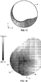
- FIG. 16 shows a pressure distribution profile for various points around the radial bearing
- FIG. 17 shows a pressure distribution profile for a plain-sleeve bearing disposed across outer bearing surface 40, without radial bearing 45.
- a plain sleeve bearing 40 has a pressure distribution that is asymmetric and loaded to one side of the bearing circumference, leading to instability of the rotor 14a within the bore 28, and hence instability in the leakage path 30 and corresponding fluid flow characteristics.
- the radial bearing 45 is preferably positioned on the rotor 14a, it is appreciated that such a projection may also be positioned on the inner wall of bore 28, with the rotor being a straight sleeve.
- the bore 28 may comprise three protrusions in the form of lands extending from a base diameter (d b ) section, with three intervening taper sections.
- a rotor-based radial bearing is preferred.
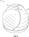
- FIG. 5 a perspective view of the hemispherical thrust bearing 47 disposed at distal end 50 of rotor 14a is shown.
- the axial thrust bearing 47 comprises three swept-tapered grooves 48.
- the thrust bearing 47 is configured to provide a pressure differential and according pumping mechanism to promote flow through leakage path 30.
- the grooves 48 are deepest near the center of the arc in a shallow-deep-shallow configuration sweeping from center outward (radially); the low pressure region occurs where the depth is transitioning from shallow to deep
- FIG. 18 shows the pressure distribution of the thrust bearing 47. As seen in FIG.
- the pressure is lowest at the distal tip where the depth is transitioning from shallow to deep, and highest (white) at the groove 48 exit, providing significant radial stability.
- the white regions extend inward as the groove tapers outward translating to axial thrust in the hemispherical or conical configuration. This pressure produces an axial distributed thrust, promoting flow into the leakage path 30, while also providing radial stability as well.
- FIG. 6 a cross-sectional view of an alternative intravascular ventricular assist pump assembly 10b is shown, having a rotor 14b with a plain-sleeve radial journal bearing surface 40 and hemispherical axial thrust bearing 49.
- Pump assembly 10b comprises pump housing 12b with first and second ends 16, 18, respectively, such that the rotor 14b is rotatably disposed within the housing12b.
- Housing 12b includes leakage inlet 22 at first end 16, the leakage inlet 22 comprising an axially-located aperture allowing flow into a cylindrical bore 28 that is disposed axially along the length of first end 16. Cylindrical bore 28 is sized such that it forms a journal bearing fit with the outside surface of bearing surface 40 of rotor 14b.
- the second end 18 of the pump housing 12b comprises a cylindrical bore 26, which is configured for housing an impeller 35 of the rotor 14b.
- the impeller 35 generally comprises a plurality of axially and radially sweeping blades 24.
- the impeller 35 draws flow radially inward from radial port 20 and into the pumping chamber defined by cylindrical bore 26. Blood flow progresses along the cylindrical bore 26 and past the conical tip 36 of the rotor 14b to exit from axial outlet or port 24.
- Flow F LP is primarily generated by pumping grooves 52 at the location of the axial bearing 49.
- pressure generated by the impeller 35 also generates some of the motive flow along an annular leakage path 30 defined by the clearance between the bearing surface 40 and the bore 28 inner wall.
- Leakage flow path 30 extends from leakage inlet 22 along the length of the cylindrical bore 28.
- a hemispherical thrust bearing 49 is disposed at distal end 50 of rotor 14b.
- the axial thrust bearing 49 comprises three longitudinally oriented grooves 52 that transverse toward the opening 22 from at or near the bearing surface 40.
- the thrust bearing 49 is configured to provide a pressure differential and according pumping mechanism to promote flow through leakage path 30. It is appreciated that groove 52 and pump assembly 12b may be able to generate greater leakage flow; however, there may be greater recirculation present within the deep, longitudinal groove 52 than in the swept-tapered groove 48.
- FIG. 7 shows a cross-sectional view of an alternative intravascular ventricular assist pump assembly 10c having a rotor 14c with a tri-lobed tapered land bearing 45 and conical axial thrust bearing 51.
- Pump assembly 10c comprises pump housing 12c with first and second ends 16, 18, respectively, with rotor 14c configured to be rotatably disposed within the housing12c.
- Housing 12c includes leakage inlet at first end 16, the leakage inlet comprising an axially-located aperture allowing flow into a cylindrical bore 28 that is disposed axially along the length of first end 16.
- Cylindrical bore 28 is sized such that it forms a journal bearing which fits with the outside surface of bearing surface 40 of rotor 14c.
- the second end 18 of the pump housing 12c comprises a cylindrical bore 26 that is configured for housing impeller 35 of the rotor 14c.
- the impeller 35 generally comprises a plurality of axially and radially sweeping blades 34.
- the impeller 35 draws flow radially inward from radial port 20 and into the pumping chamber defined by cylindrical bore 26. Blood flow progresses along the cylindrical bore 26 and past the conical tip 36 of the rotor 14c to exit from axial outlet or port 24.
- Flow F LP is primarily generated by pumping grooves 56 at the location of the axial bearing 51.
- pressure generated by the impeller 35 also generates motive force for flow along an annular leakage path 30 defined by the clearance between the bearing surface 40 and the bore 28 inner wall. Leakage flow path 30 extends from leakage inlet 22 along the length of the cylindrical bore 28.
- Pump 10c also comprises a tri-lobed radial bearing 45 to provide additional stability and flow characteristics to the rotor 14c.
- Radial bearing 45 is shown at a location adjacent to neck 38 and radial port.
- the radial bearing 45 generally comprises three lands 46 extending outward from a base-diameter section 42.
- a taper 44 transitions each land 46 and base-diameter section 42.
- a conical thrust bearing 51 is disposed at conical tip 54 of rotor 14c.
- the axial thrust bearing 51 comprises three longitudinally oriented grooves 56 that transverse toward the conical tip 54 from at or near the bearing surface 40.
- the thrust bearing 51 is configured to provide a pressure differential and according pumping mechanism to promote flow through leakage path 30.
- the conical bearing is similar to the hemispherical bearing in that it can generate both radial and axial forces/pressures with a single set of grooves/features, as opposed to a flat axial bearing ( FIG. 8 ), which may employ one set of tapered-lands in the radial direction and another set of tapered-lands in the axial direction.
- a conical axial bearing design may include tapered-land grooves in place of or in addition to longitudinal grooves 56.
- a hemispherical bearing may allow more pivoting action (e.g. ball-in-socket joint), where pivoting may be less prevalent with a conical bearing.
- a conical bearing allows variability of the axial-to-radial force distribution by the angle of the cone.
- FIG. 8 shows a cross-sectional view of an alternative intravascular ventricular assist pump assembly 10d having a rotor 14d with a tri-lobed tapered land bearing 45 and flat axial thrust bearing 53.
- Pump assembly 10d comprises pump housing 12d with first and second ends 16, 18, respectively, with rotor 14d configured to be rotatably disposed within the housing12d.
- Housing 12d includes leakage inlet 22 at first end 16, the leakage inlet 22 comprising an axially-located aperture allowing flow into a cylindrical bore 28 that is disposed axially along the length of first end 16.
- Cylindrical bore 28 is sized such that it forms a journal bearing which fits with the outside surface of bearing surface 40 of rotor 14d.
- the second end 18 of the pump housing 12d comprises a cylindrical bore 26 that is configured for housing impeller 35 of the rotor 14d.
- the impeller 35 generally comprises a plurality of axially and radially sweeping blades 34.
- the impeller 35 draws flow radially inward from radial port 20 and into the pumping chamber defined by cylindrical bore 26. Blood flow progresses along the cylindrical bore 26 and past the conical tip 36 of the rotor 14d to exit from radial outlet or port 24.
- Flow F LP is primarily generated by pumping grooves 58 at the location of the axial bearing 53.
- pressure generated by the impeller 35 also generates motive force for flow along an annular leakage path 30 defined by the clearance between the bearing surface 40 and the bore 28 inner wall. Leakage flow path 30 extends from leakage inlet 22 along the length of the cylindrical bore 28.
- Pump 10d also comprises a tri-lobed radial bearing 45 to provide additional stability and flow characteristics to the rotor 14d.
- Radial bearing 45 is shown at a location adjacent to neck 38 and radial port.
- the radial bearing 45 generally comprises three lands 46 extending outward from a base-diameter section 42.
- a taper 44 transitions each land 46 and base-diameter section 42.
- a flat axial thrust bearing 53 is disposed at flat end 59 of rotor 14d.
- the axial thrust bearing 53 comprises three longitudinally-oriented sweeping- tapered grooves 58 that transverse toward the conical flat end 59.
- the thrust bearing 53 is configured to provide a pressure differential and according pumping mechanism to promote flow through leakage path 30.
- the flat bearing may also benefit from two bearing feature sets - one radial and one axial.
- FIG. 9 is cross-sectional view of an alternative intravascular ventricular assist pump assembly 10e having a rotor 14d with a first tri-lobed tapered land bearing 45, a second tri-lobed tapered land bearing 55, and hemispherical axial thrust bearing 47.
- Pump assembly 10e comprises pump housing 12e with first and second ends 16, 18, respectively, with rotor 14e configured to be rotatably disposed within the housing12e.
- Housing 12e includes leakage inlet 22 at first end 16, the leakage inlet 22 comprising an axially-located aperture allowing flow into a cylindrical bore 28 that is disposed axially along the length of first end 16. Cylindrical bore 28 is sized such that it forms a journal bearing fit with the outside surface of bearing surface 40 of rotor 14e.
- the second end 18 of the pump housing 12e comprises a cylindrical bore 26 that is configured for housing impeller 35 of the rotor 14e.
- the impeller 35 generally comprises a plurality of axially and radially sweeping blades 34.
- the impeller 35 draws flow radially inward from radial port 20 and into the pumping chamber defined by cylindrical bore 26. Blood flow progresses along the cylindrical bore 26 and past the conical tip 36 of the rotor 14e to exit from axial outlet or port 24.
- Flow F LP is primarily generated by pumping grooves 48 at the location of the axial bearing 47.
- pressure generated by the impeller 35 also generates motive force for flow along an annular leakage path 30 defined by the clearance between the bearing surface 40 and the bore 28 inner wall. Leakage flow path 30 extends from leakage inlet 22 along the length of the cylindrical bore 28.
- pump 10e comprises a tri-lobed radial bearing 45 to provide additional stability and flow characteristics to the rotor 14e.
- Radial bearing 45 is shown at a location adjacent to neck 38 and radial port.
- the radial bearing 45 generally comprises three lands 46 extending outward from a base-diameter section 42.
- a taper 44 transitions each land 46 and base-diameter section 42.
- a second radial bearing 55 is disposed adjacent or near the hemispherical end 50.
- Radial bearing 55 generally comprises three lands 64 extending outward from a base-diameter section 60. A taper 62 transitions each land 64 and base-diameter section 60.
- the second or aft radial bearing 55 operates in a similar or identical fashion as first or forward radial bearing 45 to provide rotational stability to the rotor 14e.
- a hemispherical thrust bearing 47 is also disposed at hemispherical end 50 of rotor 14e.
- the axial thrust bearing 47 comprises three swept-tapered grooves 48.
- the thrust bearing 47 is configured to provide a pressure differential and according pumping mechanism to promote flow through leakage path 30. This pressure produces an axial distributed thrust, promoting flow into the leakage path 30, while also providing radial stability as well.
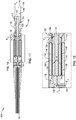
- FIG. 10 through FIG. 12 show a minimally invasive intravascular ventricular assist pump assembly 100 with reversed bearing flow.
- FIG. 10 shows a side view of the pump assembly 100
- FIG. 11 is a cross-sectional view of the pump assembly 100.
- FIG. 12 shows an expanded detail view of the cross-sectional view of FIG. 11 .
- Pump assembly 100 employs a rotor 114 with integral attachment of the solid rotor shaft to helical blades 124 of impeller 140 (stator blades 125 may also be included on the housing), and operates with similar principles of hydrodynamic suspension as shown and described by the preceding embodiments.
- the solid rotor 114 comprises rotor magnets 146 that interact with motor stator 144.
- Motor stator 144 comprises an electrically conductive coil (not shown) that is adapted to be coupled to a power source (not shown) via leads 120, and is positioned relative to the rotor magnet 146 to form a flux gap motor interface such that, in an operating mode upon activation by the power source, electrical current flow through the motor stator 144 coil creates a magnetic flux field that extends across a flux gap clearance (i.e. leakage path 130) between the rotor 114 and housing 112 and that displaces the rotor magnet 146 sufficient to torque the rotor 114 and rotate the rotor 114 within the journal bearing clearance 130 and bore 106 of end 118 of housing 112. It is also appreciated that the motor stator coil 144 may be axially offset with respect to the rotor magnet 146 to form an axial force or preload of the rotor end into the bore of the housing.
- FIG. 11 and FIG. 12 may similarly be implemented for providing rotor motion for any of the pump embodiments 10a through 10e shown in FIG. 1 through FIG. 9 .
- Motor detail was not included in FIG. 1 through FIG. 9 to allow for highlight the radial and thrust bearing configurations and flow characteristics.
- motor configurations detailed in U.S. Patent No. 8,409,276, issued on April 2, 2013 may be used where appropriate on the embodiments of the present description.
- Rotation of rotor 114 is supported within bore 132 of housing 112 via a hydrodynamic journal bearing formed from outer surface 148 of the rotor 114, the inner surface of bore 132, and a journal bearing clearance defined by leakage path 130 separating the two. It is appreciated that leakage path 130 is sized to form the journal bearing clearance similar to leakage path 30 of the pumps 10a through 10e shown in FIG. 1 through FIG. 9 . It is appreciated that in all embodiments described herein, the rotor 114 (or any of the rotors 14a through 14e of FIG. 1 - FIG.
- impeller 140 Upon rotation of rotor 114, impeller 140 draws axial input flow F IA through opening or port 116 at end 118 of housing 112, past rotor tip 142 and into pumping chamber 108 defined by bore 106. Propelled fluid then flows radially outward as F OR through radial ports 122. It is appreciated that ports 122 are oriented such that the output flow F OR exits with a radial and axial component (e.g. 45 degrees) with respect to the longitudinal axis of the rotor 114 and housing 112.
- a radial and axial component e.g. 45 degrees
- radial input flow F IR is input from a radial aperture 126 opposite the impeller 140 and pumping chamber 108 from the radial output ports 122.
- the input flow F IR is fed into an axial channel 136 and dispersed along aft end 128 of rotor 114 (which shares a similar clearance with the aft wall of chamber 132 as rotor bearing surface 148).
- Flow F LP is driven along the leak path 130 by geometry (i.e. pumping grooves) at 128 and/or 134.
- leak path flow F LP can be reversed (from that depicted in this embodiment) based on the geometry at 128 and 134, and relative pressures at 122 and 142. Input flow F IR then migrates along the length of leakage path 130, lubricating the journal bearing, before exiting with flow at output ports 122.
- FIG. 13 through FIG. 15 show a minimally invasive intravascular ventricular assist pump assembly 150 with reversed bearing flow.
- FIG. 13 shows a side view of the pump assembly 150 while
- FIG. 14 is a cross-sectional view of the pump assembly 150.
- FIG. 15 shows an expanded detail view of the cross-sectional view of FIG. 14 .
- Pump assembly 150 employs a rotor 114 with integral attachment of the solid rotor shaft to helical blades 154 of impeller 140 (stator blades 155 may also be included on the housing), and operates with similar principles of hydrodynamic suspension as shown and described by the preceding embodiments.
- the rotor 114 comprises a central channel 156 and rotor magnets 146 that interact with motor stator 144.
- Motor stator 144 comprises an electrically conductive coil (not shown) that is adapted to be coupled to a power source (not shown), and is positioned relative to the rotor magnet 146 to form a flux gap motor interface such that, in an operating mode upon activation by the power source, electrical current flow through the motor stator 144 coil creates a magnetic flux field that extends across a flux gap clearance (i.e. leakage path 130) between the rotor 114 and housing 112 and that displaces the rotor magnet 146 sufficient to torque the rotor 114 and rotate the rotor 114 within the journal bearing clearance 130 and bore 106 of end 118 of housing 112.
- a flux gap clearance i.e. leakage path 130
- Rotation of rotor 114 is supported within bore 132 of housing 112 via a hydrodynamic journal bearing formed from outer surface 148 of the rotor 114, the inner surface of bore 132, and a journal bearing clearance defined by leakage path 130 separating the two.
- impeller 140 Upon rotation of rotor 114, impeller 140 draws axial input flow F IA through port or opening 116 at end 118 of housing 112, past rotor tip 142 and into pumping chamber 108 defined by bore 106. Propelled fluid then flows radially outward as F OR through radial ports 122. It is appreciated that ports 122 are oriented such that the output flow F OR exits with a radial and axial component (e.g. 45 degrees) with respect to the longitudinal axis of the rotor 114 and housing 112.
- a radial and axial component e.g. 45 degrees
- leakage path input flow F IL is input from an annular aperture 134 located at the radial output port 22 and forward extent of the journal bearing.
- F IL is driven by geometry (i.e. pumping grooves) on the rotor at 134.
- the direction of leak path flow F LP can be reversed (from that depicted in this embodiment) based on the geometry at 128 and 134, and relative pressures at 122 and 142.
- the input flow F IL is fed into and migrates along the length of leakage path 130, lubricating the journal bearing, before being dispersed along aft end 128 of rotor 114 (which shares a similar clearance with the aft wall of chamber 132 as rotor bearing surface 148).
- Input flow F IR then with flows radially inward toward axial central channel 156 where it is then fed along the length of rotor 114 through the central channel 156 where it is output as axial flow F OA at tip 142 of the rotor 114.
- a flexible cannula not shown may be attached to the pump body or housing 112 at end 118 of either pump 100 or pump 150.
- the pump 100/150 would draw input flow F IA of blood from within a first end of cannula, the second end of the cannula being positioned at a different location in the circulatory system.
- different hydraulic pumping elements are employed to reverse the flow direction relative to the cannula and radially displaced flow ports 122.
- the aperture 116 at end 118 and first end cannula would be the pump outflow, and the radial slots or ports 122 would serve as the pump inlet.
- Minimally invasive insertion is considered of particular benefit to the extent that it allows the implementation of VADs (e.g. LV/LA, or RV/RA) without a thoracotomy or cardiopulmonary bypass.
- Central vascular access is considered of particular benefit to the extent that it is achieved via peripheral vascular access, such as for example using fluoroscopic guidance, for the placement of either an intravascular pump or specialized cannulas.
- Less invasive insertion is considered of particular benefit to the extent that it includes placing the LVAD with a limited surgical incision and without cardiopulmonary bypass.
- Methods which eliminate the need for vascular anastomoses are furthermore considered very advantageous, and are beneficially achieved according to certain of the present embodiments.
- Adaptation to an insertion method facilitated by thorascopic techniques further simplifies the procedure, and is also achieved by certain of the present embodiments.
- Minimally invasive placement of LVADS is generally considered to fall, predominately, within the domain of the interventional cardiologist (though clearly other adequately trained and capable physicians may practice the present disclosure).
- Adaptation for use by such interventionalist is provided by certain of the present embodiments, in particular in that such devices generally allow at least one of, and preferably more than one or all of: 1) a simple means for achieving non-thoracotomy vascular access, 2) small cannula systems and miniature pumps suitable for insertion in peripheral arteries, 3) small pumps suitable for subcutaneous implantation on the chest wall, and 4) pumps capable of operating reliably for months to years in an ambulatory setting.
- An ability to provide minimally or less invasive implantation of LVADs capable of operating reliably in extended ambulatory is a particular benefit presented by certain of the present embodiments and not previously possible by devices and methods of prior disclosures or use.
- Various methods are made available by certain present embodiments and which are based on transvascular techniques familiar to the interventional cardiologist. Such methods typically employ placement of a flexible cannula retrograde across the aortic valve to serve as an inflow conduit to a pump. Non-thoracotomy placement of the inflow cannula will typically be via peripheral arterial access.
- One illustrative method employs placement of a miniature intravascular pump which receives power from an external controller and battery via a percutaneous wire.
- a pump system that includes a miniaturized pump (e.g. any of pumps 10a through 10e, 100, or 150 illustrated in FIG. 1 through FIG. 15 ) that is placed within an artery of an arterial system.
- An inflow cannula is placed retrograde across an aortic valve into left ventricle of heart.
- the pump outlet e.g. axial outlet or port 24 in pumps 10a through 10e or port 116 of pump 100 or 150 in reverse flow mode
- Blood is then removed from the left ventricle via the inflow cannula and pumped into the ascending aorta via port 24, thus, directly assisting the left ventricle.
- Diastolic heart failure may also be assisted by placing the pump inflow in the left atrium (LA) and sending blood to the aorta.
- LA left atrium
- power may be supplied to the pump 10a through 10e, 100, or 150 via a percutaneous wire (e.g. wiring 120 shown in FIG. 11 ) from an externally worn motor controller and rechargeable battery system (not shown).
- a percutaneous wire e.g. wiring 120 shown in FIG. 11
- the wire is coupled from the external system components to the pump via the subclavian artery.
- implantable battery and controller may be used, which is powered via transcutaneous electron transfer (TET).
- TET transcutaneous electron transfer
- a system may incorporate the anatomical placement of a pump located in a subcutaneous pouch (not shown) in a pectoral region of a patient.
- the inflow of the pump e.g. port 116 shown in FIG. 11
- a second outflow cannula connects to the outflow of the pump and returns blood to the arterial system - in this case, via an anastomosis at the contralateral subclavian artery. So configured, blood is removed from the left ventricle and returned to the systemic circulation, thus, directly assisting the left ventricle.
- a percutaneous wire may be used to supply power and/or control to the pump via an externally worn motor controller and rechargeable battery system.
- the pump system, implant configuration, and surgical methods may be conducted without requiring anastomosis of inflow or outflow cannulas to major vessel walls. It is also to be appreciated that these non-anastomotic methods could be adapted to a mini-thoracotomy or thorascopic approach without the need for cardiopulmonary bypass or anastomosis of a vascular graft.
- a pump system employs a pump (e.g. any of pumps 10a through 10e, 100, or 150 illustrated in FIG. 1 through FIG. 15 ) that is positioned in a left ventricle and with an outlet cannula (e.g. coupled to port 24 of pumps 10a through 10e) that is passed antegrade through the aortic valve.
- a pump e.g. any of pumps 10a through 10e, 100, or 150 illustrated in FIG. 1 through FIG. 15
- an outlet cannula e.g. coupled to port 24 of pumps 10a through 10e
- This surgical procedure may be implemented via a small thoracotomy.
- the pericardium is opened and traction is placed on the ventricular apex.
- a thin walled trochar is then advanced into the ventricular cavity.
- the pump such as a forward flow pump, is then advanced into the left ventricle and the flexible outflow cannula (not shown) is readily advanced antegrade across the aortic valve .
- the pump is then anchored at the ventricular apex using an anchor assembly, which may be chosen of suitable construction and operation in context with the system and methods described as apparent to one of ordinary skill.
- the pump draws blood through ports (e.g. radial inlet port 20 in any of pumps 10a through 10e) in the housing, and pumps the blood forward through the outlet cannula into the supravalvular aorta.
- the aortic leaflets would generally provide sufficient seal around the outlet cannula.
- less invasive surgical insertion with a vascular anastomosis is performed via a small thoracotomy without cardiopulmonary bypass.
- such method may proceed for example as follows.
- the pericardium is opened and traction applied to the ventricular apex.
- a thin walled inflow cannula is inserted into the left ventricle.
- the outflow graft may be anastomosed to the descending thoracic aorta.
- the outflow graft could be tunneled to the subclavian or femoral artery for anastomosis.
- a pump is then placed between the inflow and outflow grafts such that blood is removed from the left ventricle and pumped into the systemic circulation.
- the pump may be implanted in the thoracic cavity, or subcutaneously, or elsewhere as may be appropriate in a particular case or technique.
- a percutaneous wire provides power to the pump via an external controller and battery system.
- LVAD pump embodiments of the present disclosure are described more fully below. Each is considered to offer certain significant potential advantages over previously disclosed or used systems. Such improvements of the certain embodiments include, without limitation, one or more of the following: simplicity of design, reduction in cost, and reduction of power consumption over existing LVAD designs, and each could readily be adapted to conventional surgical insertion. Moreover, certain embodiments are considered to present the highly beneficial advantage of combining low profile, minimally invasive or less invasive delivery, with longevity of life as extended ambulatory implants.
- outer diameter and length of the pumps described herein may be readily adjusted to suit an appropriate parameter for a particular application to optimize motor performance and hydrodynamic bearing support for radial constraint of the rotating assembly.
- the pumps of the present description allow for a size envelope that is well suited for insertion into the left ventricular apex or atrium via a mini-thoracotomy and would occupy very little extra-cardiac volume.
- a vascular graft from the pump outlet would typically be anastomosed to an aorta or a subclavian artery.
- the pumps according to the present description may also be constructed small enough that it could be located on the anterior chest wall and receive blood from a transthoracic cannula to the left heart and return flow to the circulation via a graft to the subclavian artery. Access to the left ventricle could also be achieved with a thin-walled cannula placed via the subclavian artery, retrograde across the aortic valve. The aortic valve leaflets would seal around the wall of the cannula. Pressurized flow from the pump outlet could be returned to the circulation via a graft to a peripheral artery such as the subclavian. Such a procedure would be in the domain of the interventional cardiologist.
- a pump as detailed in the present description may be inserted into the left ventricular apex or atrium via a mini-thoracotomy, and would occupy very little extra-cardiac volume.
- a vascular graft from the pump outlet could be anastomosed to the aorta or the subclavian artery.
- the pump is also small enough that it could be located on the anterior chest wall and receive blood from a transthoracic cannula to the left heart and return flow to the circulation via a graft to the subclavian artery.
- access to the left heart could be achieved with a thin-walled cannula placed via the subclavian artery, retrograde across the aortic valve left and flow returned to the circulation via a graft to the subclavian artery.
- the combination of features of the pumps of the present description are generally suited for direct placement in the left ventricle or atria, though radially enlarged features if appropriately constructed or otherwise modified to be collapsed during delivery may allow for more reduced profiles for minimally or less invasive delivery.
- a proximal end of an outflow cannula (not shown) is coupled to the output (e.g. port 24 of any of pumps 10a through 10e) of the pump, with the distal end inserted through a small hole in the ventricular apex and the outflow cannula passed antegrade across the aortic valve such that the tip of the cannula was above the aortic valve.
- the aortic valve leaflets would seal around the cannula wall.
- the outflow cannula could be reinforced or, possibly an inflatable pantaloon design to minimize abrasion of the valve leaflets.
- the cannula diameter could be much smaller than the pump body.
- the outer diameter of the outflow cannula as it traverses the aortic valve could be for example approximately 7 mm.
- the main body of the pump with the pump inlet would remain in the left ventricle. During pump operation blood would be pump from the left ventricle into the supravalvular aorta.
- certain mating or cooperating parts such as rotor magnets and motor stator backirons are shown in specific relative locations to each other according to the specific illustrative embodiments.
- other specific arrangements relative between such components are also contemplated and may also be suitable or even of particular benefit in certain circumstances or applications.
- the back iron of motor stator embodiments shown is typically shown aligned with the rotor magnet, it may instead be partially longitudinally displaced from the rotor magnet in resting condition. This resting displacement may be configured in order to maximize the displacement force from the magnetic attraction between these components counter-directionally against opposite longitudinal displacement forces incurred by the rotor within the housing when the magnetic flux gap motor is activated.
- any of the radial or axial bearings detailed in pumps 10a through 10e may be used in the rotor configurations shown in pumps 100 and 150.
- any of the magnetic drive /actuator components detailed in pumps 100 and 150 may be used in the configurations shown in pumps 10a through 10e.
Landscapes
- Health & Medical Sciences (AREA)
- Engineering & Computer Science (AREA)
- Heart & Thoracic Surgery (AREA)
- Cardiology (AREA)
- Life Sciences & Earth Sciences (AREA)
- Animal Behavior & Ethology (AREA)
- Mechanical Engineering (AREA)
- Anesthesiology (AREA)
- Biomedical Technology (AREA)
- Hematology (AREA)
- Veterinary Medicine (AREA)
- Public Health (AREA)
- General Health & Medical Sciences (AREA)
- Vascular Medicine (AREA)
- Fluid Mechanics (AREA)
- Physics & Mathematics (AREA)
- Human Computer Interaction (AREA)
- External Artificial Organs (AREA)
- Structures Of Non-Positive Displacement Pumps (AREA)
- Transplantation (AREA)
Claims (14)
- Dispositif d'assistance cardiaque, comprenant :un rotor (14a, 14b, 14c, 14d, 14e) ;un carter de pompe (12a, 12b, 12c, 12d, 12e) ;ledit rotor (14a, 14b, 14c, 14d, 14e) comprenant un arbre avec une surface extérieure et une roue (35) s'étendant depuis l'arbre au niveau d'un premier emplacement sur la surface extérieure ;ladite surface extérieure comprenant une surface de palier extérieure (40) au niveau d'un second emplacement sur l'arbre, et un palier axial (47) au niveau ou à proximité de la surface de palier extérieure (40) ;le palier axial (47) étant conçu pour être disposé axialement à côté de l'entrée de fuite (22) du carter ; etledit carter de pompe (12a, 12b, 12c, 12d, 12e) comprenant au moins un alésage cylindrique (26, 28) conçu pour définir une chambre de pompage et une surface de palier intérieure à l'intérieur du carter de pompe ;dans une configuration de fonctionnement, le rotor (14a, 14b, 14c, 14d, 14e) étant positionné dans l'au moins un alésage cylindrique (26, 28) de sorte que la roue (35) tourne dans la chambre de pompage (26) lors de l'actionnement du rotor (14a, 14b, 14c, 14d, 14e) ;ladite surface de palier intérieure (28) du carter de pompe étant étroitement ajustée à ladite surface de palier extérieure (40) dudit arbre pour former un jeu annulaire entre elles de sorte que, pendant l'actionnement du rotor (14a, 14b, 14c, 14d, 14e), la surface de palier intérieure et la surface de palier extérieure forment un palier de tourillon hydrodynamique ;le carter de pompe comprenant une entrée de fuite (22) en communication fluidique avec le jeu annulaire ;pendant l'actionnement du rotor (14a, 14b, 14c, 14d, 14e), le jeu annulaire fonctionnant comme un trajet de fuite pour permettre l'écoulement du sang dans l'entrée de fuite (22), et sur la longueur du jeu annulaire entre la surface de palier intérieure et la surface de palier extérieure ; etle palier axial (47) comprenant une pluralité de rainures (48) formant un palier de poussée hydrodynamique avec une surface d'accouplement de l'au moins un alésage cylindrique (26, 28) pour s'opposer à la poussée axiale du rotor et favoriser l'écoulement de sang dans le trajet d'écoulement de fuite depuis l'entrée de fuite (22).
- Dispositif selon la revendication 1, ledit rotor (14a, 14b, 14c, 14d, 14e) étant principalement suspendu dans la direction radiale à l'intérieur dudit carter par des forces de poussée hydrodynamiques générées par le mouvement relatif dudit rotor (14a, 14b, 14c, 14d, 14e) par rapport audit carter de pompe (12a, 12b, 12c, 12d, 12e) et à l'intérieur de celui-ci.
- Dispositif selon la revendication 1 :ledit rotor (14a, 14b, 14c, 14d, 14e) comprenant au moins un aimant de rotor (146) situé dans la surface de palier dudit arbre ;le carter de pompe (12a, 12b, 12c, 12d, 12e) comprenant un stator de moteur (144) ayant une bobine positionnée à l'opposé dudit au moins un aimant de rotor (146) par rapport au jeu annulaire ; etl'actionnement du rotor étant affecté par le flux de courant électrique qui traverse le stator du moteur (144) pour générer un champ de flux magnétique qui s'étend sur le trajet de flux de fuite pour déplacer l'au moins un aimant de rotor (146).
- Dispositif selon la revendication 1, l'au moins un alésage cylindrique (26, 28) comprenant un premier alésage disposé à une première extrémité du carter de pompe (12a, 12b, 12c, 12d, 12e), le premier alésage définissant la surface de palier intérieure (28) conçue pour loger la surface de palier extérieure (40) du rotor (14a, 14b, 14c, 14d, 14e), et un second alésage (26) à une seconde extrémité du carter de pompe (12a, 12b, 12c, 12d, 12e), le second alésage (26) étant conçu pour loger la roue (35) et la chambre de pompage, le carter de pompe comprenant en outre :un orifice radial (20) disposé entre le premier alésage et le second alésage ;la rotation de la roue (35) aspirant l'écoulement de sang à travers l'orifice radial (20) et dans la chambre de pompage sur la longueur du second alésage et à travers un orifice axial (24) disposé au niveau de la seconde extrémité du carter de pompe ;l'entrée de fuite (22) étant disposée en face de la sortie au niveau de la première extrémité du carter de pompe (12a, 12b, 12c, 12d, 12e) ; etle sang circulant le long du trajet de fuite étant expulsé dans l'orifice radial (20).
- Dispositif selon la revendication 1, comprenant en outre :un palier radial (45) au niveau ou à proximité de la surface de palier extérieure (40) ;ledit palier radial (45) comprenant une pluralité de méplats (46) faisant saillie radialement de la surface de palier extérieure (40) ;la pluralité de méplats (46) étant espacés sur une circonférence de l'arbre de rotor ;l'actionnement du rotor (14a, 14b, 14c, 14d, 14e) générant un profil de pression à l'intérieur de l'espace annulaire ; etles méplats (46) du palier radial répartissent sensiblement le profil de pression de manière symétrique sur la circonférence de la surface de palier extérieure (40).
- Dispositif selon la revendication 5, chacun de la pluralité de méplats (46) se rétrécissant progressivement sur la circonférence à partir d'une section de diamètre de base du rotor (14a, 14b, 14c, 14d, 14e), la section de diamètre de base ayant un diamètre égal à la surface de palier extérieure (40).
- Dispositif selon la revendication 1, le palier de poussée axiale (47) comprenant une surface hémisphérique.
- Dispositif selon la revendication 1, la pluralité de rainures (48, 58) comprenant des rainures recourbées-effilées.
- Dispositif selon la revendication 1, le palier de poussée axiale (47) comprenant une surface conique.
- Dispositif selon la revendication 1, le palier de poussée axiale (47) comprenant une surface plane.
- Dispositif selon la revendication 10, la pluralité de rainures (48) comprenant des rainures recourbées-effilées orientées longitudinalement qui sont transversales à la surface plane.
- Dispositif selon la revendication 9, la pluralité de rainures (48) comprenant des rainures orientées longitudinalement qui sont transversales par rapport à une pointe conique de la surface conique.
- Dispositif selon la revendication 5, l'au moins un alésage cylindrique (26, 28) comprenant un premier alésage (28) disposé au niveau d'une première extrémité du carter de pompe (12a, 12b, 12c, 12d, 12e), le premier alésage (28) définissant la surface de palier intérieure conçue pour loger la surface de palier extérieure (40) du rotor, et un second alésage (26) au niveau d'une seconde extrémité du carter de pompe (12a, 12b, 12c, 12d, 12e), le second alésage (26) étant conçu pour loger la roue (35) et la chambre de pompage, le carter de pompe (12a, 12b, 12c, 12d, 12e) comprenant en outre :un orifice radial (20) disposé entre le premier alésage (28) et le second alésage (26) ;la rotation de la roue (35) aspirant l'écoulement de sang à travers l'orifice radial (20) et dans la chambre de pompage sur la longueur du second alésage (26) et à travers une sortie (24) disposée au niveau de la seconde extrémité du carter de pompe (12a, 12b, 12c, 12d, 12e) ; etl'entrée de fuite étant disposée au niveau d'une extrémité du carter de pompe (12a, 12b, 12c, 12d, 12e) opposée à la sortie (24).
- Dispositif selon la revendication 13, le palier radial étant disposé sur la première extrémité de la surface de palier extérieure (40) adjacente à l'orifice radial (20), le dispositif comprenant en outre :un second palier radial comprenant un second ensemble de méplats faisant saillie radialement de la surface de palier extérieure (40) ;le second ensemble de méplats étant espacé sur une seconde circonférence de l'arbre de rotor (14a, 14b, 14c, 14d, 14e) ;le second palier radial disposé sur une seconde extrémité de la surface de palier adjacente à l'entrée de fuite (22).
Applications Claiming Priority (1)
| Application Number | Priority Date | Filing Date | Title |
|---|---|---|---|
| PCT/US2016/030445 WO2017192119A1 (fr) | 2016-05-02 | 2016-05-02 | Dispositif d'assistance cardiaque |
Publications (3)
| Publication Number | Publication Date |
|---|---|
| EP3452134A1 EP3452134A1 (fr) | 2019-03-13 |
| EP3452134A4 EP3452134A4 (fr) | 2020-01-01 |
| EP3452134B1 true EP3452134B1 (fr) | 2021-03-10 |
Family
ID=60203114
Family Applications (1)
| Application Number | Title | Priority Date | Filing Date |
|---|---|---|---|
| EP16901122.8A Active EP3452134B1 (fr) | 2016-05-02 | 2016-05-02 | Dispositif d'assistance cardiaque |
Country Status (7)
| Country | Link |
|---|---|
| US (3) | US10918774B2 (fr) |
| EP (1) | EP3452134B1 (fr) |
| JP (1) | JP7072523B2 (fr) |
| CN (1) | CN109414533B (fr) |
| AU (1) | AU2016405653B2 (fr) |
| CA (1) | CA3022818C (fr) |
| WO (1) | WO2017192119A1 (fr) |
Families Citing this family (74)
| Publication number | Priority date | Publication date | Assignee | Title |
|---|---|---|---|---|
| AU2005272610B2 (en) | 2004-08-13 | 2011-10-20 | Procyrion, Inc. | Method and apparatus for long-term assisting a left ventricle to pump blood |
| US12151092B2 (en) | 2012-11-06 | 2024-11-26 | Procardia Llc | Mechanical circulatory support device with centrifugal impeller designed for implantation in the descending aorta |
| US10857274B2 (en) | 2012-11-06 | 2020-12-08 | Queen Mary University Of London | Mechanical circulatory support device with centrifugal impeller designed for implantation in the descending aorta |
| FR3040304B1 (fr) * | 2015-08-25 | 2020-11-13 | Fineheart | Pompe de flux sanguin pour assistance ventriculaire |
| ES2959221T3 (es) | 2015-09-25 | 2024-02-21 | Procyrion Inc | Bomba de sangre intravascular no oclusiva que proporciona hemólisis reducida |
| AU2016405653B2 (en) | 2016-05-02 | 2021-05-13 | Star Bp, Inc. | Heart assist device |
| US12090310B2 (en) | 2016-10-03 | 2024-09-17 | Procardia Llc | Mechanical circulatory support device with axial flow turbomachine optimized for heart failure and cardio-renal syndrome by implantation in the descending aorta |
| US11524153B2 (en) | 2016-10-03 | 2022-12-13 | Queen Mary University Of London | Mechanical circulatory support device with axial flow turbomachine optimized for heart failure and cardio-renal syndrome by implantation in the descending aorta |
| US10888646B2 (en) | 2017-04-28 | 2021-01-12 | Nuheart As | Ventricular assist device and method |
| US10537670B2 (en) | 2017-04-28 | 2020-01-21 | Nuheart As | Ventricular assist device and method |
| EP4732889A2 (fr) | 2017-06-07 | 2026-04-29 | Supira Medical, Inc. | Dispositifs de déplacement de fluide intravasculaire, systèmes et procédés d'utilisation |
| US11511103B2 (en) | 2017-11-13 | 2022-11-29 | Shifamed Holdings, Llc | Intravascular fluid movement devices, systems, and methods of use |
| CN111770765B (zh) * | 2018-01-08 | 2024-05-14 | 星辰Bp有限公司 | 心脏辅助装置 |
| DE102018201030B4 (de) | 2018-01-24 | 2025-10-16 | Kardion Gmbh | Magnetkuppelelement mit magnetischer Lagerungsfunktion |
| JP7410034B2 (ja) | 2018-02-01 | 2024-01-09 | シファメド・ホールディングス・エルエルシー | 血管内血液ポンプならびに使用および製造の方法 |
| WO2019195480A1 (fr) | 2018-04-04 | 2019-10-10 | Theodosios Korakianitis | Dispositif mécanique amovible d'assistance circulatoire destiné à être utilisé à court terme |
| DE102018207575A1 (de) | 2018-05-16 | 2019-11-21 | Kardion Gmbh | Magnetische Stirndreh-Kupplung zur Übertragung von Drehmomenten |
| DE102018207611A1 (de) | 2018-05-16 | 2019-11-21 | Kardion Gmbh | Rotorlagerungssystem |
| DE102018207594A1 (de) | 2018-05-16 | 2019-11-21 | Kardion Gmbh | Rotor, Magnetkupplungsvorrichtung, Elektromotor für ein Herzunterstützungssystem, Pumpeneinheit für ein Herzunterstützungssystem sowie Verfahren zum Herstellen eines Rotors |
| DE102018208538A1 (de) | 2018-05-30 | 2019-12-05 | Kardion Gmbh | Intravasale Blutpumpe und Verfahren zur Herstellung von elektrischen Leiterbahnen |
| DE102018208549A1 (de) | 2018-05-30 | 2019-12-05 | Kardion Gmbh | Elektronikmodul für ein Herzunterstützungssystem und Verfahren zum Herstellen eines Elektronikmoduls für ein Herzunterstützungssystem |
| DE102018208539A1 (de) | 2018-05-30 | 2019-12-05 | Kardion Gmbh | Motorgehäusemodul zum Abdichten eines Motorraums eines Motors eines Herzunterstützungssystems und Herzunterstützungssystem und Verfahren zum Montieren eines Herzunterstützungssystems |
| DE102018208550A1 (de) | 2018-05-30 | 2019-12-05 | Kardion Gmbh | Leitungsvorrichtung zum Leiten eines Blutstroms für ein Herzunterstützungssystem, Herzunterstützungssystem und Verfahren zum Herstellen einer Leitungsvorrichtung |
| DE102018208541A1 (de) | 2018-05-30 | 2019-12-05 | Kardion Gmbh | Axialpumpe für ein Herzunterstützungssystem und Verfahren zum Herstellen einer Axialpumpe für ein Herzunterstützungssystem |
| DE102018210058A1 (de) | 2018-06-21 | 2019-12-24 | Kardion Gmbh | Statorschaufelvorrichtung zur Strömungsführung eines aus einer Austrittsöffnung eines Herzunterstützungssystems ausströmenden Fluids, Herzunterstützungssystem mit Statorschaufelvorrichtung, Verfahren zum Betreiben einer Statorschaufelvorrichtung und Herstellverfahren |
| DE102018210076A1 (de) | 2018-06-21 | 2019-12-24 | Kardion Gmbh | Verfahren und Vorrichtung zum Erkennen eines Verschleißzustands eines Herzunterstützungssystems, Verfahren und Vorrichtung zum Betreiben eines Herzunterstützungssystems und Herzunterstützungssystem |
| DE102018211297A1 (de) | 2018-07-09 | 2020-01-09 | Kardion Gmbh | Herzunterstützungssystem und Verfahren zur Überwachung der Integrität einer Haltestruktur eines Herzunterstützungssystems |
| DE102018211327A1 (de) | 2018-07-10 | 2020-01-16 | Kardion Gmbh | Laufrad für ein implantierbares, vaskuläres Unterstützungssystem |
| DE102018211328A1 (de) | 2018-07-10 | 2020-01-16 | Kardion Gmbh | Laufradgehäuse für ein implantierbares, vaskuläres Unterstützungssystem |
| DE102018212153A1 (de) | 2018-07-20 | 2020-01-23 | Kardion Gmbh | Zulaufleitung für eine Pumpeneinheit eines Herzunterstützungssystems, Herzunterstützungssystem und Verfahren zum Herstellen einer Zulaufleitung für eine Pumpeneinheit eines Herzunterstützungssystems |
| WO2020028537A1 (fr) | 2018-07-31 | 2020-02-06 | Shifamed Holdings, Llc | Pompes sanguines intravasculaires et procédés d'utilisation |
| AU2019320533B2 (en) | 2018-08-07 | 2024-11-21 | Kardion Gmbh | Bearing device for a cardiac support system, and method for flushing an intermediate space in a bearing device for a cardiac support system |
| WO2020073047A1 (fr) | 2018-10-05 | 2020-04-09 | Shifamed Holdings, Llc | Pompes à sang intravasculaires et procédés d'utilisation |
| FR3095018B1 (fr) * | 2019-04-10 | 2022-12-02 | Fineheart | Pompe cardiaque à couplage magnétique et à flux inverse. |
| EP3990095A4 (fr) | 2019-06-28 | 2023-07-12 | Theodosios Alexander | Support circulatoire mécanique amovible pour utilisation à court terme |
| WO2021011473A1 (fr) | 2019-07-12 | 2021-01-21 | Shifamed Holdings, Llc | Pompes à sang intravasculaires et méthode d'utilisation et procédé de fabrication |
| US11654275B2 (en) | 2019-07-22 | 2023-05-23 | Shifamed Holdings, Llc | Intravascular blood pumps with struts and methods of use and manufacture |
| EP4010046A4 (fr) | 2019-08-07 | 2023-08-30 | Calomeni, Michael | Pompes sanguines à cathéter et boîtiers de pompe pliants |
| US11730946B2 (en) | 2019-08-12 | 2023-08-22 | Boston Scientific Scimed, Inc. | Flow enhancement for circulatory support device |
| US12171994B2 (en) * | 2019-09-11 | 2024-12-24 | Boston Scientific Scimed, Inc. | Reduced thrombosis blood pump with washout bearing |
| US10987456B2 (en) * | 2019-09-23 | 2021-04-27 | Synecor Llc | Devices for use in extracting percutaneous ventricular assist devices |
| EP4034192B1 (fr) | 2019-09-25 | 2025-12-24 | Supira Medical, Inc. | Dispositifs et systèmes de pompes à sang intravasculaires et leurs procédés d'utilisation et de commande |
| EP4034221B1 (fr) | 2019-09-25 | 2024-11-13 | Shifamed Holdings, LLC | Pompes à sang de cathéter et boîtiers de pompe pliables |
| WO2021062260A1 (fr) | 2019-09-25 | 2021-04-01 | Shifamed Holdings, Llc | Pompes à sang de cathéter et conduits sanguins pliables |
| CA3160442A1 (fr) | 2019-12-03 | 2021-06-10 | Procyrion, Inc. | Pompes a sang |
| EP4072650A4 (fr) | 2019-12-11 | 2024-01-10 | Shifamed Holdings, LLC | Pompes à sang d'aorte descendante et de veine cave |
| WO2021119413A1 (fr) | 2019-12-13 | 2021-06-17 | Procyrion, Inc. | Structures de support pour pompes à sang intravasculaires |
| US12599758B2 (en) | 2019-12-19 | 2026-04-14 | Shifamed Holdings, Llc | Intravascular blood pumps, motors, and fluid control |
| US11441601B1 (en) * | 2019-12-20 | 2022-09-13 | RBTS Inc. | Blood pump bearing system with optimized geometry, materials, and manufacturing method |
| DE102020102474A1 (de) | 2020-01-31 | 2021-08-05 | Kardion Gmbh | Pumpe zum Fördern eines Fluids und Verfahren zum Herstellen einer Pumpe |
| EP3884969A1 (fr) * | 2020-03-27 | 2021-09-29 | Abiomed Europe GmbH | Pompe sanguine |
| EP3884968A1 (fr) * | 2020-03-27 | 2021-09-29 | Abiomed Europe GmbH | Pompe d'assistance circulatoire |
| CN111420144B (zh) * | 2020-04-10 | 2024-07-05 | 华侨大学 | 一种用于人工心脏的非叶轮转子无阀泵 |
| CN111888552B (zh) * | 2020-07-06 | 2021-05-18 | 河海大学 | 差项迭代曲线流道的单轴变速二级异步心脏泵及使用方法 |
| CN119327026B (zh) * | 2020-07-31 | 2025-10-31 | 深圳核心医疗科技股份有限公司 | 介入式心室辅助装置 |
| CA3192451A1 (fr) | 2020-09-14 | 2022-03-17 | Johannes Bette | Pompe de support cardiovasculaire dotee d'un impulseur a zone d'ecoulement variable |
| JP2023550938A (ja) | 2020-11-20 | 2023-12-06 | カルディオン ゲーエムベーハー | ガイドワイヤ補助具付き機械的循環支持システム |
| CN112472999B (zh) * | 2020-12-22 | 2025-03-21 | 深圳核心医疗科技股份有限公司 | 血泵 |
| CN117157122A (zh) | 2021-02-10 | 2023-12-01 | 波士顿科学国际有限公司 | 用于血液动力学支持泵的磁性推进器和轴承 |
| WO2022221512A1 (fr) | 2021-04-14 | 2022-10-20 | Boston Scientific Scimed Inc. | Pointe flexible pour dispositif de support circulatoire transvalvulaire |
| CN115474950A (zh) * | 2021-06-15 | 2022-12-16 | 浙江迪远医疗器械有限公司 | 能够防凝血的血液泵 |
| CN115475327A (zh) * | 2021-06-15 | 2022-12-16 | 浙江迪远医疗器械有限公司 | 能够降温的血液泵 |
| US20240316334A1 (en) * | 2021-07-01 | 2024-09-26 | Corisma Cardiovascular | Devices and methods for supporting cardiac function |
| US20240285927A1 (en) * | 2021-07-01 | 2024-08-29 | Corisma Cardiovascular | Axial flow pumps for supporting cardiac function |
| CN118215524A (zh) | 2021-11-16 | 2024-06-18 | 波士顿科学国际有限公司 | 有利于减少溶血的经皮循环支持系统 |
| AU2022389899B2 (en) | 2021-11-16 | 2025-02-06 | Boston Scientific Scimed Inc. | Percutaneous circulatory support device including proximal pressure sensor |
| JP7693114B2 (ja) | 2021-11-17 | 2025-06-16 | ボストン サイエンティフィック サイムド,インコーポレイテッド | 損傷なくガイドワイヤを並進することを容易にするためのデバイスハウジング形態 |
| US12133976B2 (en) | 2021-11-23 | 2024-11-05 | Boston Scientific Scimed, Inc. | Percutaneous circulatory support device facilitating reduced hemolysis class |
| CN114177516B (zh) * | 2021-12-22 | 2024-05-14 | 江苏大学 | 一种用于左心室辅助的大流量两级导管泵及其使用方法 |
| US12341463B2 (en) | 2022-06-06 | 2025-06-24 | Star Bp, Inc. | Blood pump controller and system |
| CN117839060A (zh) * | 2022-07-08 | 2024-04-09 | 深圳核心医疗科技股份有限公司 | 驱动机构和血泵 |
| CN115282468B (zh) * | 2022-08-03 | 2024-09-24 | 上海炫脉医疗科技有限公司 | 一种介入式血泵 |
| CN115253063A (zh) * | 2022-09-02 | 2022-11-01 | 深圳核心医疗科技有限公司 | 驱动机构和血泵 |
| EP4676584A2 (fr) * | 2023-03-10 | 2026-01-14 | Star BP, Inc. | Système et méthode de traitement d'une déficience cardiovasculaire |
Family Cites Families (15)
| Publication number | Priority date | Publication date | Assignee | Title |
|---|---|---|---|---|
| US5211546A (en) * | 1990-05-29 | 1993-05-18 | Nu-Tech Industries, Inc. | Axial flow blood pump with hydrodynamically suspended rotor |
| US5527159A (en) * | 1993-11-10 | 1996-06-18 | The United States Of America As Represented By The Administrator Of The National Aeronautics And Space Administration | Rotary blood pump |
| DE10108815B4 (de) * | 2001-02-16 | 2006-03-16 | Berlin Heart Ag | Vorrichtung zur axialen Förderung von Körperflüssigkeiten |
| US8419609B2 (en) * | 2005-10-05 | 2013-04-16 | Heartware Inc. | Impeller for a rotary ventricular assist device |
| EP1898971B1 (fr) * | 2005-06-06 | 2015-03-11 | The Cleveland Clinic Foundation | Pompe sanguine |
| US20070231135A1 (en) * | 2006-03-31 | 2007-10-04 | Orqis Medical Corporation | Rotary Blood Pump |
| AU2007266459B2 (en) * | 2006-05-31 | 2013-01-17 | Star Bp, Inc. | Heart assist device |
| US8731664B2 (en) * | 2007-06-14 | 2014-05-20 | Calon Cardio Technology Limited | Reduced diameter axial rotary pump for cardiac assist |
| GB0906642D0 (en) * | 2009-04-17 | 2009-06-03 | Calon Cardio Technology Ltd | Cardiac pump |
| DE102012202411B4 (de) * | 2012-02-16 | 2018-07-05 | Abiomed Europe Gmbh | Intravasale blutpumpe |
| JP5828459B2 (ja) * | 2012-03-30 | 2015-12-09 | 国立研究開発法人産業技術総合研究所 | 遠心血液ポンプ |
| US9144638B2 (en) * | 2013-03-14 | 2015-09-29 | Thoratec Corporation | Blood pump rotor bearings |
| US10111994B2 (en) * | 2013-05-14 | 2018-10-30 | Heartware, Inc. | Blood pump with separate mixed-flow and axial-flow impeller stages and multi-stage stators |
| EP3821938B1 (fr) * | 2015-03-18 | 2024-07-03 | Abiomed Europe GmbH | Pompe sanguine |
| AU2016405653B2 (en) | 2016-05-02 | 2021-05-13 | Star Bp, Inc. | Heart assist device |
-
2016
- 2016-05-02 AU AU2016405653A patent/AU2016405653B2/en active Active
- 2016-05-02 CA CA3022818A patent/CA3022818C/fr active Active
- 2016-05-02 JP JP2018557314A patent/JP7072523B2/ja active Active
- 2016-05-02 WO PCT/US2016/030445 patent/WO2017192119A1/fr not_active Ceased
- 2016-05-02 EP EP16901122.8A patent/EP3452134B1/fr active Active
- 2016-05-02 CN CN201680085926.2A patent/CN109414533B/zh active Active
-
2018
- 2018-10-30 US US16/175,795 patent/US10918774B2/en active Active
-
2021
- 2021-02-04 US US17/168,031 patent/US11904155B2/en active Active
-
2024
- 2024-01-12 US US18/412,086 patent/US20240149047A1/en active Pending
Non-Patent Citations (1)
| Title |
|---|
| None * |
Also Published As
| Publication number | Publication date |
|---|---|
| WO2017192119A1 (fr) | 2017-11-09 |
| US20190125948A1 (en) | 2019-05-02 |
| AU2016405653A1 (en) | 2018-11-22 |
| CN109414533B (zh) | 2021-07-06 |
| CN109414533A (zh) | 2019-03-01 |
| EP3452134A1 (fr) | 2019-03-13 |
| JP2019516458A (ja) | 2019-06-20 |
| EP3452134A4 (fr) | 2020-01-01 |
| US11904155B2 (en) | 2024-02-20 |
| CA3022818A1 (fr) | 2017-11-09 |
| CA3022818C (fr) | 2023-03-28 |
| JP7072523B2 (ja) | 2022-05-20 |
| US20210236799A1 (en) | 2021-08-05 |
| US10918774B2 (en) | 2021-02-16 |
| AU2016405653B2 (en) | 2021-05-13 |
| US20240149047A1 (en) | 2024-05-09 |
Similar Documents
| Publication | Publication Date | Title |
|---|---|---|
| US20240149047A1 (en) | Heart assist device | |
| US12076546B2 (en) | Heart assist device | |
| US9737651B2 (en) | Heart assist device | |
| AU2013203301B2 (en) | Heart Assist Device | |
| JP5172955B2 (ja) | 直径が縮小された心臓補助用軸回転ポンプ |
Legal Events
| Date | Code | Title | Description |
|---|---|---|---|
| STAA | Information on the status of an ep patent application or granted ep patent |
Free format text: STATUS: THE INTERNATIONAL PUBLICATION HAS BEEN MADE |
|
| PUAI | Public reference made under article 153(3) epc to a published international application that has entered the european phase |
Free format text: ORIGINAL CODE: 0009012 |
|
| STAA | Information on the status of an ep patent application or granted ep patent |
Free format text: STATUS: REQUEST FOR EXAMINATION WAS MADE |
|
| 17P | Request for examination filed |
Effective date: 20181116 |
|
| AK | Designated contracting states |
Kind code of ref document: A1 Designated state(s): AL AT BE BG CH CY CZ DE DK EE ES FI FR GB GR HR HU IE IS IT LI LT LU LV MC MK MT NL NO PL PT RO RS SE SI SK SM TR |
|
| AX | Request for extension of the european patent |
Extension state: BA ME |
|
| DAV | Request for validation of the european patent (deleted) | ||
| DAX | Request for extension of the european patent (deleted) | ||
| A4 | Supplementary search report drawn up and despatched |
Effective date: 20191204 |
|
| RIC1 | Information provided on ipc code assigned before grant |
Ipc: A61M 1/12 20060101ALI20191128BHEP Ipc: A61M 1/10 20060101AFI20191128BHEP |
|
| GRAP | Despatch of communication of intention to grant a patent |
Free format text: ORIGINAL CODE: EPIDOSNIGR1 |
|
| GRAJ | Information related to disapproval of communication of intention to grant by the applicant or resumption of examination proceedings by the epo deleted |
Free format text: ORIGINAL CODE: EPIDOSDIGR1 |
|
| GRAP | Despatch of communication of intention to grant a patent |
Free format text: ORIGINAL CODE: EPIDOSNIGR1 |
|
| STAA | Information on the status of an ep patent application or granted ep patent |
Free format text: STATUS: GRANT OF PATENT IS INTENDED |
|
| INTG | Intention to grant announced |
Effective date: 20201006 |
|
| GRAS | Grant fee paid |
Free format text: ORIGINAL CODE: EPIDOSNIGR3 |
|
| GRAA | (expected) grant |
Free format text: ORIGINAL CODE: 0009210 |
|
| STAA | Information on the status of an ep patent application or granted ep patent |
Free format text: STATUS: THE PATENT HAS BEEN GRANTED |
|
| AK | Designated contracting states |
Kind code of ref document: B1 Designated state(s): AL AT BE BG CH CY CZ DE DK EE ES FI FR GB GR HR HU IE IS IT LI LT LU LV MC MK MT NL NO PL PT RO RS SE SI SK SM TR |
|
| REG | Reference to a national code |
Ref country code: GB Ref legal event code: FG4D |
|
| REG | Reference to a national code |
Ref country code: AT Ref legal event code: REF Ref document number: 1369098 Country of ref document: AT Kind code of ref document: T Effective date: 20210315 Ref country code: CH Ref legal event code: EP |
|
| REG | Reference to a national code |
Ref country code: DE Ref legal event code: R096 Ref document number: 602016054261 Country of ref document: DE |
|
| REG | Reference to a national code |
Ref country code: IE Ref legal event code: FG4D |
|
| REG | Reference to a national code |
Ref country code: LT Ref legal event code: MG9D |
|
| PG25 | Lapsed in a contracting state [announced via postgrant information from national office to epo] |
Ref country code: HR Free format text: LAPSE BECAUSE OF FAILURE TO SUBMIT A TRANSLATION OF THE DESCRIPTION OR TO PAY THE FEE WITHIN THE PRESCRIBED TIME-LIMIT Effective date: 20210310 Ref country code: FI Free format text: LAPSE BECAUSE OF FAILURE TO SUBMIT A TRANSLATION OF THE DESCRIPTION OR TO PAY THE FEE WITHIN THE PRESCRIBED TIME-LIMIT Effective date: 20210310 Ref country code: GR Free format text: LAPSE BECAUSE OF FAILURE TO SUBMIT A TRANSLATION OF THE DESCRIPTION OR TO PAY THE FEE WITHIN THE PRESCRIBED TIME-LIMIT Effective date: 20210611 Ref country code: NO Free format text: LAPSE BECAUSE OF FAILURE TO SUBMIT A TRANSLATION OF THE DESCRIPTION OR TO PAY THE FEE WITHIN THE PRESCRIBED TIME-LIMIT Effective date: 20210610 Ref country code: LT Free format text: LAPSE BECAUSE OF FAILURE TO SUBMIT A TRANSLATION OF THE DESCRIPTION OR TO PAY THE FEE WITHIN THE PRESCRIBED TIME-LIMIT Effective date: 20210310 Ref country code: BG Free format text: LAPSE BECAUSE OF FAILURE TO SUBMIT A TRANSLATION OF THE DESCRIPTION OR TO PAY THE FEE WITHIN THE PRESCRIBED TIME-LIMIT Effective date: 20210610 |
|
| REG | Reference to a national code |
Ref country code: AT Ref legal event code: MK05 Ref document number: 1369098 Country of ref document: AT Kind code of ref document: T Effective date: 20210310 |
|
| REG | Reference to a national code |
Ref country code: NL Ref legal event code: MP Effective date: 20210310 |
|
| PG25 | Lapsed in a contracting state [announced via postgrant information from national office to epo] |
Ref country code: SE Free format text: LAPSE BECAUSE OF FAILURE TO SUBMIT A TRANSLATION OF THE DESCRIPTION OR TO PAY THE FEE WITHIN THE PRESCRIBED TIME-LIMIT Effective date: 20210310 Ref country code: LV Free format text: LAPSE BECAUSE OF FAILURE TO SUBMIT A TRANSLATION OF THE DESCRIPTION OR TO PAY THE FEE WITHIN THE PRESCRIBED TIME-LIMIT Effective date: 20210310 Ref country code: RS Free format text: LAPSE BECAUSE OF FAILURE TO SUBMIT A TRANSLATION OF THE DESCRIPTION OR TO PAY THE FEE WITHIN THE PRESCRIBED TIME-LIMIT Effective date: 20210310 |
|
| PG25 | Lapsed in a contracting state [announced via postgrant information from national office to epo] |
Ref country code: NL Free format text: LAPSE BECAUSE OF FAILURE TO SUBMIT A TRANSLATION OF THE DESCRIPTION OR TO PAY THE FEE WITHIN THE PRESCRIBED TIME-LIMIT Effective date: 20210310 |
|
| PG25 | Lapsed in a contracting state [announced via postgrant information from national office to epo] |
Ref country code: EE Free format text: LAPSE BECAUSE OF FAILURE TO SUBMIT A TRANSLATION OF THE DESCRIPTION OR TO PAY THE FEE WITHIN THE PRESCRIBED TIME-LIMIT Effective date: 20210310 Ref country code: CZ Free format text: LAPSE BECAUSE OF FAILURE TO SUBMIT A TRANSLATION OF THE DESCRIPTION OR TO PAY THE FEE WITHIN THE PRESCRIBED TIME-LIMIT Effective date: 20210310 Ref country code: SM Free format text: LAPSE BECAUSE OF FAILURE TO SUBMIT A TRANSLATION OF THE DESCRIPTION OR TO PAY THE FEE WITHIN THE PRESCRIBED TIME-LIMIT Effective date: 20210310 Ref country code: AT Free format text: LAPSE BECAUSE OF FAILURE TO SUBMIT A TRANSLATION OF THE DESCRIPTION OR TO PAY THE FEE WITHIN THE PRESCRIBED TIME-LIMIT Effective date: 20210310 |
|
| PG25 | Lapsed in a contracting state [announced via postgrant information from national office to epo] |
Ref country code: PT Free format text: LAPSE BECAUSE OF FAILURE TO SUBMIT A TRANSLATION OF THE DESCRIPTION OR TO PAY THE FEE WITHIN THE PRESCRIBED TIME-LIMIT Effective date: 20210712 Ref country code: PL Free format text: LAPSE BECAUSE OF FAILURE TO SUBMIT A TRANSLATION OF THE DESCRIPTION OR TO PAY THE FEE WITHIN THE PRESCRIBED TIME-LIMIT Effective date: 20210310 Ref country code: SK Free format text: LAPSE BECAUSE OF FAILURE TO SUBMIT A TRANSLATION OF THE DESCRIPTION OR TO PAY THE FEE WITHIN THE PRESCRIBED TIME-LIMIT Effective date: 20210310 Ref country code: RO Free format text: LAPSE BECAUSE OF FAILURE TO SUBMIT A TRANSLATION OF THE DESCRIPTION OR TO PAY THE FEE WITHIN THE PRESCRIBED TIME-LIMIT Effective date: 20210310 Ref country code: IS Free format text: LAPSE BECAUSE OF FAILURE TO SUBMIT A TRANSLATION OF THE DESCRIPTION OR TO PAY THE FEE WITHIN THE PRESCRIBED TIME-LIMIT Effective date: 20210710 |
|
| REG | Reference to a national code |
Ref country code: DE Ref legal event code: R097 Ref document number: 602016054261 Country of ref document: DE |
|
| REG | Reference to a national code |
Ref country code: CH Ref legal event code: PL |
|
| PLBE | No opposition filed within time limit |
Free format text: ORIGINAL CODE: 0009261 |
|
| STAA | Information on the status of an ep patent application or granted ep patent |
Free format text: STATUS: NO OPPOSITION FILED WITHIN TIME LIMIT |
|
| PG25 | Lapsed in a contracting state [announced via postgrant information from national office to epo] |
Ref country code: ES Free format text: LAPSE BECAUSE OF FAILURE TO SUBMIT A TRANSLATION OF THE DESCRIPTION OR TO PAY THE FEE WITHIN THE PRESCRIBED TIME-LIMIT Effective date: 20210310 Ref country code: LI Free format text: LAPSE BECAUSE OF NON-PAYMENT OF DUE FEES Effective date: 20210531 Ref country code: LU Free format text: LAPSE BECAUSE OF NON-PAYMENT OF DUE FEES Effective date: 20210502 Ref country code: MC Free format text: LAPSE BECAUSE OF FAILURE TO SUBMIT A TRANSLATION OF THE DESCRIPTION OR TO PAY THE FEE WITHIN THE PRESCRIBED TIME-LIMIT Effective date: 20210310 Ref country code: AL Free format text: LAPSE BECAUSE OF FAILURE TO SUBMIT A TRANSLATION OF THE DESCRIPTION OR TO PAY THE FEE WITHIN THE PRESCRIBED TIME-LIMIT Effective date: 20210310 Ref country code: CH Free format text: LAPSE BECAUSE OF NON-PAYMENT OF DUE FEES Effective date: 20210531 Ref country code: DK Free format text: LAPSE BECAUSE OF FAILURE TO SUBMIT A TRANSLATION OF THE DESCRIPTION OR TO PAY THE FEE WITHIN THE PRESCRIBED TIME-LIMIT Effective date: 20210310 |
|
| REG | Reference to a national code |
Ref country code: BE Ref legal event code: MM Effective date: 20210531 |
|
| 26N | No opposition filed |
Effective date: 20211213 |
|
| PG25 | Lapsed in a contracting state [announced via postgrant information from national office to epo] |
Ref country code: SI Free format text: LAPSE BECAUSE OF FAILURE TO SUBMIT A TRANSLATION OF THE DESCRIPTION OR TO PAY THE FEE WITHIN THE PRESCRIBED TIME-LIMIT Effective date: 20210310 |
|
| PG25 | Lapsed in a contracting state [announced via postgrant information from national office to epo] |
Ref country code: IT Free format text: LAPSE BECAUSE OF FAILURE TO SUBMIT A TRANSLATION OF THE DESCRIPTION OR TO PAY THE FEE WITHIN THE PRESCRIBED TIME-LIMIT Effective date: 20210310 Ref country code: IE Free format text: LAPSE BECAUSE OF NON-PAYMENT OF DUE FEES Effective date: 20210502 |
|
| PG25 | Lapsed in a contracting state [announced via postgrant information from national office to epo] |
Ref country code: IS Free format text: LAPSE BECAUSE OF FAILURE TO SUBMIT A TRANSLATION OF THE DESCRIPTION OR TO PAY THE FEE WITHIN THE PRESCRIBED TIME-LIMIT Effective date: 20210710 |
|
| PG25 | Lapsed in a contracting state [announced via postgrant information from national office to epo] |
Ref country code: BE Free format text: LAPSE BECAUSE OF NON-PAYMENT OF DUE FEES Effective date: 20210531 |
|
| PG25 | Lapsed in a contracting state [announced via postgrant information from national office to epo] |
Ref country code: CY Free format text: LAPSE BECAUSE OF FAILURE TO SUBMIT A TRANSLATION OF THE DESCRIPTION OR TO PAY THE FEE WITHIN THE PRESCRIBED TIME-LIMIT Effective date: 20210310 |
|
| P01 | Opt-out of the competence of the unified patent court (upc) registered |
Effective date: 20230526 |
|
| PG25 | Lapsed in a contracting state [announced via postgrant information from national office to epo] |
Ref country code: HU Free format text: LAPSE BECAUSE OF FAILURE TO SUBMIT A TRANSLATION OF THE DESCRIPTION OR TO PAY THE FEE WITHIN THE PRESCRIBED TIME-LIMIT; INVALID AB INITIO Effective date: 20160502 |
|
| REG | Reference to a national code |
Ref country code: DE Ref legal event code: R081 Ref document number: 602016054261 Country of ref document: DE Owner name: STAR BP, INC., SPRING, US Free format text: FORMER OWNER: VADOVATIONS, INC., OKLAHOMA CITY, OKLA., US |
|
| REG | Reference to a national code |
Ref country code: GB Ref legal event code: 732E Free format text: REGISTERED BETWEEN 20231123 AND 20231129 |
|
| PG25 | Lapsed in a contracting state [announced via postgrant information from national office to epo] |
Ref country code: MK Free format text: LAPSE BECAUSE OF FAILURE TO SUBMIT A TRANSLATION OF THE DESCRIPTION OR TO PAY THE FEE WITHIN THE PRESCRIBED TIME-LIMIT Effective date: 20210310 |
|
| PG25 | Lapsed in a contracting state [announced via postgrant information from national office to epo] |
Ref country code: TR Free format text: LAPSE BECAUSE OF FAILURE TO SUBMIT A TRANSLATION OF THE DESCRIPTION OR TO PAY THE FEE WITHIN THE PRESCRIBED TIME-LIMIT Effective date: 20210310 |
|
| PG25 | Lapsed in a contracting state [announced via postgrant information from national office to epo] |
Ref country code: MT Free format text: LAPSE BECAUSE OF FAILURE TO SUBMIT A TRANSLATION OF THE DESCRIPTION OR TO PAY THE FEE WITHIN THE PRESCRIBED TIME-LIMIT Effective date: 20210310 |
|
| PGFP | Annual fee paid to national office [announced via postgrant information from national office to epo] |
Ref country code: DE Payment date: 20250521 Year of fee payment: 10 |
|
| PGFP | Annual fee paid to national office [announced via postgrant information from national office to epo] |
Ref country code: GB Payment date: 20250507 Year of fee payment: 10 |
|
| PGFP | Annual fee paid to national office [announced via postgrant information from national office to epo] |
Ref country code: FR Payment date: 20250528 Year of fee payment: 10 |