EP2508108A2 - Dispositif destiné à la livraison de marchandises - Google Patents
Dispositif destiné à la livraison de marchandises Download PDFInfo
- Publication number
- EP2508108A2 EP2508108A2 EP12163206A EP12163206A EP2508108A2 EP 2508108 A2 EP2508108 A2 EP 2508108A2 EP 12163206 A EP12163206 A EP 12163206A EP 12163206 A EP12163206 A EP 12163206A EP 2508108 A2 EP2508108 A2 EP 2508108A2
- Authority
- EP
- European Patent Office
- Prior art keywords
- housing
- door
- goods
- data
- locking
- Prior art date
- Legal status (The legal status is an assumption and is not a legal conclusion. Google has not performed a legal analysis and makes no representation as to the accuracy of the status listed.)
- Withdrawn
Links
Images








Classifications
-
- A—HUMAN NECESSITIES
- A47—FURNITURE; DOMESTIC ARTICLES OR APPLIANCES; COFFEE MILLS; SPICE MILLS; SUCTION CLEANERS IN GENERAL
- A47G—HOUSEHOLD OR TABLE EQUIPMENT
- A47G29/00—Supports, holders, or containers for household use, not provided for in groups A47G1/00-A47G27/00 or A47G33/00
- A47G29/14—Deposit receptacles for food, e.g. breakfast, milk, or large parcels; Similar receptacles for food or large parcels with appliances for preventing unauthorised removal of the deposited articles, i.e. food or large parcels
- A47G29/141—Deposit receptacles for food, e.g. breakfast, milk, or large parcels; Similar receptacles for food or large parcels with appliances for preventing unauthorised removal of the deposited articles, i.e. food or large parcels comprising electronically controlled locking means
-
- A—HUMAN NECESSITIES
- A47—FURNITURE; DOMESTIC ARTICLES OR APPLIANCES; COFFEE MILLS; SPICE MILLS; SUCTION CLEANERS IN GENERAL
- A47G—HOUSEHOLD OR TABLE EQUIPMENT
- A47G29/00—Supports, holders, or containers for household use, not provided for in groups A47G1/00-A47G27/00 or A47G33/00
- A47G29/14—Deposit receptacles for food, e.g. breakfast, milk, or large parcels; Similar receptacles for food or large parcels with appliances for preventing unauthorised removal of the deposited articles, i.e. food or large parcels
- A47G29/141—Deposit receptacles for food, e.g. breakfast, milk, or large parcels; Similar receptacles for food or large parcels with appliances for preventing unauthorised removal of the deposited articles, i.e. food or large parcels comprising electronically controlled locking means
- A47G2029/145—Deposit receptacles for food, e.g. breakfast, milk, or large parcels; Similar receptacles for food or large parcels with appliances for preventing unauthorised removal of the deposited articles, i.e. food or large parcels comprising electronically controlled locking means the receptacle comprising means for identifying a deposit; Deposits carrying identification means, e.g. a bar code
Definitions
- the invention relates to a device for delivering goods with a housing, which housing has four side surfaces, a rear wall and a closable with a door element opening for the introduction and removal of goods, wherein the door element has a lock having closure device.
- the invention also relates to a system for delivering goods with at least two devices according to the invention.
- the invention also relates to a device for the delivery of goods, comprising a housing, which housing at least four side surfaces, a rear wall and a closable with a door element opening for the introduction and removal of goods, for example Postvertriebs publisheden.
- the housing preferably has a substantially cubic shape, wherein the components of the housing are preferably formed of metal.
- the invention also relates to a method for operating a device for delivering goods, comprising the method steps: a) inserting a goods to be delivered in a housing of the device; b) providing and transmitting a data record to an authorized recipient of the goods; c) opening the housing for removal of the goods by using the record.
- a device for the delivery of goods with a housing and a locking device which is actuated via a data code delivered to a receiver, wherein the data code has two parts, of which the receiver constantly contains a part as individualized data carrier while the second part is customizable and deliverable depending on the recipient.
- the closure device has a displaceable latch, which engages in the closed position in a recess in the region of a side wall of the housing.
- the housing of the devices in particular according to the modular principle, are formed combined.
- an identifier of the goods to be delivered is read with a reading device, which identifier contains information, in particular physical parameters, about the goods to be delivered, wherein the device is controlled as a function of the read identifier.
- housings are provided which, starting from a first housing with a predetermined height have further housing with half the height and / or the quarter height of the housing.
- the door element of the housing may be articulated to a vertically extending longitudinal edge of a side part of the housing.
- an articulation of the door element in the region of a horizontally extending longitudinal edge of a side member is provided, which is then the bottom or the lid of the housing.
- the door element has a closure device, the function of which will be described in detail below.
- this closure device which usually has a lock, for example an electronic lock
- the housing can be closed against unauthorized access, so that only authorized persons have access to the interior of the housing, the recording example of a document to be delivered and / or serves to be delivered.
- the DE 101 48 300 B4 describes a method for delivering such goods and a device for this purpose.
- the content of this patent is also the subject matter of this application made in full, as this patent describes a thoroughly perpetuating method and a device that proves to be quite reliable.
- the width of the housing at different heights is identical 55 cm and the depth of the housing at 35 cm.
- Such housings are suitable to accommodate larger packages of goods.
- the lock arranged in the door can be designed such that it has a displaceable latch, which engages in the closed position in a recess in the region of a side wall of the housing, in particular in the case of the housings with a lesser height.
- the latch engages behind a structural element of the side wall, for example a folded sheet metal strip in the closed position. If the lock is operated by an authorized person, the bolt is moved from its closed position into the open position in which the door element is pivotable about an axis forming the stop.
- a further embodiment is formed in that the lock is arranged substantially in the center of the door element and four espagnolettes are drivable via the lock, which engage in the region of the four longitudinal sides of the door element in corresponding recesses or behind corresponding projections of the housing in the region of the side walls.
- substantially central arrangement of the lock in the door element is meant in particular that the lock is arranged in the center of gravity of the door element.
- the housing may be provided in a simple manner for wall mounting.
- the housing may be screwed in the region of the bottom with a substantially U-shaped console, wherein the screw is accessible only via the interior of the housing.
- the housing may be connected in the bottom area with at least two, preferably triangular support elements, which are screwed on the one hand to the bottom of the housing or connected in some other way. On the other hand, these support elements are screwed to a housing.
- the rear wall of the housing has bores which serve to receive screws or the like in order to screw the housing directly to a building wall.
- the holes are arranged in a preferred hole pattern, so that without preparatory work, an attachment of the housing to a building wall in prescribed, that is, the optimal attachmentamstellender way is possible.
- the housing in the area of Outer surface of the rear wall has a receptacle which is formed corresponding to a mounting plate, so that the housing after attachment of the mounting plate on the building wall is pushed onto this and optionally connected to this via a screw connection.
- This embodiment has the advantage that in a first step, the mounting plate is attached to the building and then the prefabricated housing with these mounting plates are connected and this damage to the housing, for example, by drilling through the rear wall of the housing or the like prevented.
- a plurality of housings can be combined with one another and can be arranged lying against one another, for example, with their side surfaces, their bottom surfaces and / or their cover surfaces, it being advantageous to connect the housings to one another by means of a screw connection in such an arrangement.
- the door member is hinged to a side wall of the housing pivotally.
- an arrangement of the door element is provided on the horizontally extending front longitudinal edge of the cover element of the housing, so that the door element is folded up when opening the housing.
- Such a housing can be easily arranged in the réellehaus- as well as in the area outside.
- the use of energy-saving and cost-effective trained and in particular customer-oriented locking systems is possible, these locking systems can be operated in a simple manner and without any special prior knowledge and training processes.
- a locking system with conventional per se Technique namely a mechanical key are formed.
- electronic locking systems are provided, which are described below.
- electronic keys are provided, which are designed for example as transponder, RFID tags, codable coins and / or bar code carrier.
- the device can be designed independently of an external energy supply by integrating a self-sufficient energy supply, for example in the form of replaceable batteries, in particular lithium cells or alkaline cells.
- a status display which can represent the state of charge of the different batteries
- this status display not only indicates the possibly faulty real state of charge of the batteries, but in addition a particular time-controlled evaluation has the state of charge independent of indicates the real state of charge of the batteries and thereby ensures that after a certain period of use, regardless of the real state of charge of the batteries, a request signal for replacing the batteries is generated.
- This embodiment serves, in particular, to improve the security of the energy supply to the effect that a deeply discharging battery precludes a further opening process. This is particularly necessary with regard to the different types of batteries, as they may not be able to be displayed on a common state of charge indicator in required accuracy in terms of their state of charge.
- the power supply is arranged in the housing so that it is accessible only when the door element is open. It has proven to be advantageous to integrate the power supply directly into the locking system.
- rechargeable energy storage can be used, the charging either takes place directly on the locking system, or at a central location, in which case the energy storage of the locking system replaced with no longer sufficient state of charge and charged the discharged energy storage at this central location and maintained for further use.
- the locking system has further features.
- About the locking system can be displayed to the deliverer and possibly also the authorized recipient, whether there is a delivery to be delivered in the housing.
- This display is preferably designed so that it only from an authorized person, in particular the deliverer can be activated by a key, in particular an electronic key is used, with which the state of the housing is read out with regard to its filling.
- the locking system on the display for the state of charge of the power supply.
- the power supply is accessible by simple means, such as simple tools for an authorized person.
- a battery compartment is provided that is closed due to possible weather conditions, in particular moisture and / or dust load with a sealed and screwed lid. After loosening the screw, provided here can be a single screw, the battery compartment is accessible and remove the batteries of the authorized person and interchangeable with new, a high state of charge having batteries.
- the locking system on an emergency opening system which can be opened only with a certain key and electronic key and an associated energy transfer.
- This additional feature has the advantage that the locking system is also operable when the state of charge of the batteries or other power supply is no longer sufficient to operate the locking system such that the open position can be achieved.
- such an emergency opening can also be achieved by controlling the closing system at a certain low state of charge in such a way that further closing due to the low state of charge is not possible.
- the deliverer or another authorized person recognizes that an improved power supply must be provided immediately, that is to say, the batteries must be replaced immediately or the rechargeable batteries must be recharged. In a simple manner, this can be achieved by the fact that upon reaching a certain state of charge, a signal from a controller to an actuator is omitted in that via this actuator, such as an electric motor, the bolt is moved into the locking position.
- This configuration prevents a device which is not fully functional from being supplied with a product to be delivered or a mailpiece to be delivered, so that subsequently the recipient is not unambiguously given the opportunity to receive the goods or the mailpiece.
- the device will be available for the receiver for a predeterminable period of time. Within this period, the recipient can carry out the mail piece intended for him or the goods intended for him by operating the locking system exclusively with a key assigned to him. If the goods or the item of mail are not received by the authorized recipient within this time interval, then the locking system generates a signal for the deliverer that the goods or the item of mail has not been removed, so that the deliverer then removes the goods and the item of mail and can deliver to a warehouse or send back to the sender. It has proven to be advantageous to make the locking system activatable during this period only with the key, and electronic key of the authorized recipient. For emergency purposes only, it may be necessary to add that opening of the device is possible with a master key.
- Such a master key can for example also be designed such that data such as date and time are stored in such an emergency opening. Incidentally, care should be taken to ensure that corresponding emergency keys are of course only accessible to a very limited group of people, so that the handling of these emergency keys in particular by the fact that such a handling is recorded in terms of data, in a simple manner is comprehensible.
- a removal of the goods inserted in the device is carried out by a janitor service. It can thereby be achieved that the receiving space available from the device is rapidly emptied, so that a following product can be picked up by the device.
- a private use of the device according to the invention can also be carried out. It is then not a device operated with respect to a multi-party house but, for example, a single device operated individually by a private household.
- a removal of goods loaded in the device by a deliverer. The users of the device can then also use the device to place goods for shipment.
- the state of the locking system that is, for example, the state of charge of the power supply, the filling state of the device and the like can be advantageously read out with external wireless data acquisition devices, so that it does not depend on a direct and immediately recognizable display in the area of the locking system or the device.
- An appropriate display can therefore be dispensed with, so that for an uninvolved third party the state of the device, in particular its filling, can not be recognized on the basis of an indication in the area of the locking system.
- the locking system provides the option of forwarding data to the recipient. For example, this can be done via a telecommunications network, in particular a mobile network by the locking system generates an SMS to the recipient after appropriate programming by the deliverer, so that the latter receives knowledge about the deposit of a product or a mailpiece, which he within the available time period can receive.
- SMS or other data transmission suitable here, for example, an e-mail
- the recipient can also be the authorization code for opening the locking system, for example, transmitted in the form of a barcode.
- a higher security bidding key such as an RFID chip, a magnetizable and thus rewritable chips, for example in the form of a coin or the like.
- the deliverer inserts a consignment to be delivered or a mailpiece to be delivered into the housing.
- the deliverer removes a data carrier with which, after the housing has been closed, it can be opened for removal of the contents for a certain period of time.
- This data carrier provides the recipient to the recipient, for example, by transfer or by throwing in a house mailbox.
- the recipient can then open the device once with the code carrier and remove the contents.
- the code carrier remains for example after a throw in a throw-in device in the housing.
- the code carrier is stored until the next filling of the housing in a sealed container, which can be opened only with a key accessible to the deliverer.
- it may be an electronic key, such as a data card or the like, which is electronically, in particular contactlessly readable and contains a secret of secrecy, which agrees with the secrecy of a locking device, which the closed container for receiving the code carrier closes and can be unlocked by this procedure.
- a data card or the like which is electronically, in particular contactlessly readable and contains a secret of secrecy, which agrees with the secrecy of a locking device, which the closed container for receiving the code carrier closes and can be unlocked by this procedure.
- the code carrier is inserted by the recipient in the receiving device and then remains freely accessible in the housing.
- the locking secret stored on the code carrier is read when inserting the code carrier and compared with the introduced during the delivery of the shipment by the deliverer code, so that when matching code of the opening process starts automatically.
- the code is also automatically stored by the deliverer.
- the deliverer opens the locking device with a master key, also in electronic form, which unlocks the door and makes the interior accessible.
- the code carrier is coded and the coding of the code carrier is also stored in the closing device, so that subsequently a single opening process of the device with the code carrier is possible with the coded code carrier.
- the door After entering the delivery of goods to be delivered or the mailpiece to be delivered, the door is closed and the closure device activated.
- each recipient gets an individualized card, with which the device can be opened, if previously the code of an individualized card is programmed by the deliverer when delivering the goods.
- the programming is carried out by the deliverer, who has for this purpose designed as a card code carrier with which the device for entering the goods delivery and / or the Postvertriebs Kunststoffs can be opened.
- opening the device when the receiving space is filled with this code carrier of the deliverer is not possible for a certain period of time, so that the device can only be opened with an individualized card of the recipient.
- the closing device switches the code of the code carrier of the delivery again to the opening of the device, so that the deliverer can subsequently remove a not picked up goods or a not picked Postvertriebswin again, so that the device is unlocked for a further delivery process.
- the security of this system is increased by the fact that the receiver holding a card to the opening receives a further code carrier, for example an RFID chip, a passive or active transponder or the like, after inserting the goods to be delivered or the postal sales item to be delivered. Only in combination of these two different secrets is now an opening of the device for removal of the goods or the Postvertriebs Kunststoffs possible. In this way, there is also the possibility that a larger number of people, for example, the residents of a multiple dwelling identical cards are issued to open the device, but allow only in combination with another code carrier to open the device.
- the deliverer can deliver this second code carrier individually to the authorized recipient and ensure that only this or a legitimized by him person can perform an opening operation of the device. Other people who have a corresponding card for opening the device, but where a second code carrier has not been transmitted, can not perform an opening operation.
- the housing of the device can for example be designed as a kit and consist of the individual side panels, the rear wall and the door.
- This embodiment has the advantage that the transport volume of such a device is greatly reduced, so that a large number of such devices can be transported in the usual mode of transport.
- the individual components of the device may be designed such that they can be screwed together or connected in another way, for example, be plugged together.
- quick connect solutions are provided, that is, for example, connectors, which may optionally then still be fixed with locking screws, it being preferred that such screws are accessible only through the interior of the device, so that a manipulation of the housing of the device from the outside with the door closed not possible.
- the transport volume of a plurality of such devices is reduced by the fact that these devices are stackable.
- This can be achieved, for example, by virtue of the fact that the housing of the device has a rear wall which has a smaller surface area than the front area of such a device, which can be closed in a door which is usually to be used finally.
- the housing receives a substantially conical shape design, so that the side walls of the housing are aligned from the front surface to the rear wall converging.
- an assembly of the housing of the device is limited to the fact that only the door still needs to be inserted into the front surface and the locking device has to be activated.
- the housing is made of metal.
- a kit of the housing it has proven to be advantageous to form the corner regions, that is, the transitions from the side walls in the bottom or lid area with reinforcing elements.
- Such reinforcing elements are formed substantially L-shaped and can be connected to the side walls or the lid or the floor, for example, welded, glued or screwed.
- the reinforcing elements have on each of its legs on a receiving element which is in the form of a door hinge, which serves to rotatably receive a pin, which pin is attached to the door of the housing.
- the door thus has two pins for rotatable mounting in the door hinges.
- each corner region of the housing has a corresponding reinforcing element, the door can be arranged to pivot in accordance with the individual requirements, for example on the left or on the right side wall or on the upper or lower side wall.
- this reinforcing element in the region of its two legs each having two receiving elements in the form of hinges, said two receiving elements of each leg are arranged on parallel to each other and oppositely disposed surfaces of the leg of the reinforcing element.
- the legs of the reinforcing element are formed substantially T-shaped. The legs can have different thicknesses.
- the design of the device as a kit also has the advantage that individual components, such as side walls, lid, floor, rear wall or door are easily replaceable, without the case of damage to a side wall, an entire housing must be re-provided.
- the side walls, the lid and the bottom have on their edge facing the door on a folded, retracted metal strip, which may for example also carry a seal which serves to seal the door relative to the housing.
- the bottom is below the free edge of this metal strip.
- the bottom of the housing in the region of the receiving space on spacer elements for example, store an inserted package at a height, so that this package can be pulled out in the direction of the surface normal of the rear wall of the receiving space without the package with a Interior facing surface of the metal strip comes into contact.
- the spacer may consist of a flat, arranged at a distance from the ground support element made of metal or plastic.
- punctiform or linear spacers as spacers. The latter have the advantage that possibly incoming moisture is collected below the storage area of the parcel or post office parcel.
- a flat edition has the advantage that different package sizes can be easily stored thereon.
- the locking device has a data memory which stores the operating data of the locking device at least over a time interval, after which this operating data can be read out via a data acquisition device and used to check the functionality of the locking device.
- the data memory stores the number of opening and closing operations, duration of the sealed housing, Manipulation attempts, time of opening and closing, date of opening and closing are saved.
- the read-out data can be managed in a central data management and used for example to optimize the time interval for the provision of goods to be delivered.
- the device can be adapted to the usage habits of the recipient. For example, in the area of holiday home settlements it may be necessary to make the time intervals for the provision of the goods in the device longer than in the area of high-traffic urban vehicle habitats.
- an identifier of the goods to be delivered be read with a reading device, which identifier contains information, in particular physical parameters, about the goods to be supplied, wherein the device is controlled as a function of the read identifier.
- the identifier can be a barcode, an RFID chip and / or the like.
- the reading device can be designed as a bar code scanner, RFID chip reading device and / or the like.
- the reader is information such as physical. Parameter of a product or data of the recipient, readable.
- the goods have an identifier in which at least one piece of information, for example the mass of the goods, the outer dimensions of the goods, in particular of the package and / or the like is stored.
- the reading device is designed to read out such identifiers.
- the device can be controlled. In particular, so device-side actions can be triggered. For example, from a selection of devices, a device corresponding to the dimensions of its receiving space to the consignment to be picked up can be selected.
- Packages to be delivered are usually provided with a barcode.
- the delivery address is stored in the barcode and it is readily possible to also include the addressee in this barcode by name.
- the data can be recorded and used to code a code carrier, which is then delivered to the authorized recipient by the delivery person.
- a data transmission can take place, which notifies the recipient that a corresponding data medium has been delivered, so that at the next opportunity by means of this data carrier, the device can open and remove the goods.
- the bar code reader is designed for reading non-visible bar codes. Not visible means that the barcode is imperceptible to the human eye.
- the barcode is designed to reflect non-visible light.
- the bar code may be covered by a filter, which filter is permeable only to infrared light, UV light and / or the like.
- the bar code reader can emit for this purpose, for example, infrared light, UV light and / or the like, which is reflected by the invisible barcode accordingly. The thus reflected infrared light, UV light and / or the like can be read and evaluated by the bar code reader.
- These data carriers are preferably designed as RFID chips that can be coded differently. These RFID chips are inexpensive to produce and provide a high level of data security because the data is neither visually nor audibly recognizable. Such an RFID chip can be thrown into the locking device in a simple manner. For this purpose, a slot is provided, in which the RFID chip is inserted. After reading the data code, the RFID chip is pulled in and, if the data code is correct, the locking device is unlocked. This process can be associated with a mechanical rotary movement of a rotary wheel, which can be unlocked with the appropriate data code and with the unlocking the locking device of the locking device can be transferred from a closed position to an open position. The activation can be done both mechanically and electronically.
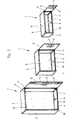
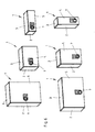
- FIG. 1 three devices of different sizes according to the invention are shown.
- Each device consists of a housing 1, the two mutually parallel side walls 2, a lid 3, a bottom 4 and a rear wall, not shown, wherein the rear wall between the side walls 2 on the one hand and the lid 3 and the bottom 4 on the other hand extends , Further, a door is provided which closes an inner space 6 of the housing 1, wherein can be locked or unlocked via an electronic locking device 7.
- the exact function of the electronic locking device 7 will be described below.
- the housing 1 of the device is cuboid, so that the interior 6 is parallelepiped.
- housing 1 have matching widths of 55 cm and matching depths of 35 cm. Differently, the housing 1 in terms of their height, wherein the in FIG. 1 housing 1 shown on the left a height of 80 cm, the in FIG. 1 in the middle illustrated housing 1 a height of 40 cm and the in FIG. 1 shown housing 1 has a height of 20 cm, so that the heights of the individual housing 1 are integer fractions of the housing 1 with the greatest height or in the reverse manner, starting from the housing 1 with the lowest height, the other housing 1 have high represent the integer multiples of the height of the housing 1 with the lowest height.
- FIG. 2 shows the housing 1 with unlocked and opened door 5 and beyond the in FIG. 1 not shown rear wall. 8
- the electronic locking device 7 has a displaceable latch 9, which can be transferred from an ejected and locked position into a retracted position as a function of an entered locking secret.
- a displaceable latch 9 In the extended, locked position of the latch 9 engages behind a umgebörtelten edge strip 10 of the left side wall 2 of the housing 1. It can also be provided a recess in the side wall 2, in the latch 9 is inserted.
- the door 5 is pivotally mounted about a pivot axis 11.
- the electronic locking device 7 has two Baskueliegel 12, which are aligned parallel to the front, free edge and are connected to arranged in the corner region of the door 5 bars, so that here the bars do not reach behind an edge strip 10 of the left side wall 2 but behind corresponding edge strips 13 in the region of the bottom 4 and the lid. 3
- the edge strips 13 are due to production technology by folding a metal sheet and also serve to increase the stability of the housing 1. The same applies with respect to the edge strips 10th
- FIG. 3 shows a basic system of an electronic locking device 7, which may have an electronic lock cylinder 14, whose function is known per se.
- the electronic lock cylinder 14 has a control device which is programmable with a locking secret.
- a key for example an electronic key in the form of a transponder, an RFID chip, a bar code, a magnetizable code carrier or the like
- a user can transmit a key of this key to the control device of the electronic lock cylinder 14. If the closing secrets of the control device in the electronic lock cylinder 14 and in the electronic key match, the electronic lock cylinder 14 is actuated via the control device, so that an opening operation of the electronic locking device is possible.
- FIG. 3 shows possible combinations of such Locking cylinder 14 with electronic keys, such as Tastureingabetechnikn, wireless keys, card readers or the like, for example, even with sophisticated systems readers for biometric features of users are possible.
- the key which can be used by way of example in combination with the lock cylinder 14 is preferably equipped in such a way that the locking secret provided by it is valid only for a specific time.
- the secret of closure is changed at regular intervals, for example after the expiration of 24 hours. So that the key can still interact as intended with the electronic locking device 7, a prior authorization of the key is required. This new authorization then lasts for 24 hours.
- This authorization or activation of the key has the advantage that increased security is given.
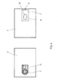
- FIG. 4 shows the door 5 of the housing 1 with the electronic locking device 7, wherein the left figure in FIG. 4 the front view of the door 5 shows, while the right picture of the FIG. 4 the back of the door 5 shows, that is the side facing the interior 6 of the housing 1 with the door 5 closed.
- the electronic locking device 7 has an accessible from the front of the door 5, slot-shaped opening 15, which serves for example the input of a data carrier, in particular an RFID chip, a transponder chip, a transponder card or even a barcode printed on a paper strip. Behind the opening, not shown in detail, a reading device is provided which the reading of the code is used to then compare this with the stored in the electronic locking device code, so that a decision on a legitimate opening process can be made.
- a data carrier in particular an RFID chip, a transponder chip, a transponder card or even a barcode printed on a paper strip.
- a charge status display can be provided here, which is not shown in more detail, but gives the user, for example a delivery agent information about the state of charge of the batteries, so that they can be replaced in time to a failure of the electronic locking device 7 in the locked state of the door. 5 avoid as much as possible.
- FIG. 4a shows the detail of an embodiment of a door 100 of a device not shown further for the delivery of goods.
- a device comprises a housing which consists of interconnected components, namely a bottom, a lid, two side walls, and a rear wall.
- the door 100 is pivotally mounted on this housing, the arrangement being in the region of a side wall.
- FIG. 4a If the door 100 is shown in front view and it can be seen that the door 100 has a first recess 102 and a second recess 103, which make accessible to the rear of the door 100 locking device 104, wherein in the region of the recess 103 is a sliding element 105 is arranged with two recesses 106 as a handle.
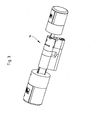
- the locking device 104 is formed with a receptacle 107, in which a in FIG. 4a illustrated first volume 108 in the form of an electronic key and a in FIG. 4a not shown second volume 109 ( FIG. 4b ) in the form of a transponder, in particular a passive transponder can be inserted.
- an optical signal device 110 for example an LED, is arranged, which, when the latch device 104 is operated correctly and correctly, generates an optical signal, for example a green light represents. By displaying, for example, a red light, an unauthorized use can also be displayed.
- the door 100 may have a further recess (not shown), which is, for example, of circular design and can receive the receptacle of a shaft for an actuating device to be rotated.
- This recess may possibly also be formed only by a material weakening, so that the pending here material of the door 100 is cut out only when needed, so that the door 100 is then provided for a rotatable actuator, with which the slider is movable.
- FIG. 4b shows a detailed view of the recess 102 in the door 100 with the receptacle 107. Furthermore, the data carrier 108 and the data carrier 109 are shown, which have a different width, length and / or material thickness.
- the data carrier 109 is designed as a passive transponder.
- the receptacle 107 For receiving the data carrier 109, the receptacle 107 has slot-shaped extensions 112 on both sides.
- Figure 4c shows the back 113 of the door 100 with the particular screwed locking device 104 attached thereto.
- the door 100 is formed in the region of the rear side 113 with two L-shaped tabs, which serves to receive a housing 115 of the locking device 104.
- the tabs 114 are connected to a leg of the rear side 113 of the door, while the second leg perpendicular to the first leg extends parallel to the rear side 113.
- the two legs are aligned with each other and engage over the housing 115.
- These legs have bores 116 which serve to receive screws, with which the housing 115 of the locking device 104 is screwed to the door 100.
- the housing 115 Arranged in the housing 115 is the electromechanics of the locking device 104, which will be described in more detail below. It can be seen that the housing 115 has a receptacle 116 for receiving the data carrier 109.
- a latch 117 is shown connected to the slider 105 (FIG. FIG. 4a ) is connected, so that this latch 117 in a recess 119 (schematically in Figure 4c indicated) of the housing or behind an edge of the housing, namely in Engages area of a side wall.
- FIG. 4d shows an alternative embodiment of a locking device 204.
- This embodiment of the locking device 204 differs from the locking device according to the FIGS. 4a to 4c by a different arrangement of the Basküle latch 218 and the activation of the Basküle latch 218, which in the embodiment of the FIGS. 4a to 4c via the slider 205 and in the embodiment according to FIG FIG. 4d via a rotary knob 246 takes place.
- the embodiment according to the according FIG. 4d is therefore below in particular with regard to the differences from the embodiment according to the FIGS. 4a to 4c described.
- FIG. 4d shows the locking unit 204 in front view.
- rotary knob 246, the Basküle latch 218 and a latch (not shown) are displaceable.
- the locking unit 204 has an unillustrated housing, which in FIG. 4d is closed with a cover plate 247 which is connected to the housing via connecting elements 248. In the area of the cover plate 247, pictograms 249 and 249 'are arranged, which indicate the function of the locking unit 204 as a function of the position of the rotary knob 246.
- the knob 246 has for this purpose a handle 250 which extends radially over the knob 246 and lifts out of a flat surface of the knob 246.
- the rotary knob 246 further has a recess 251 arranged on the edge, which releases an area below the rotary knob 246 in the region of the cover plate 247, in which area alternatively or additionally a display can be provided which indicates the closed position or the open position of the locking unit 204.
- the time of an event for example, a date and a time in a particular device can be detected.
- This data can be stored on a data carrier 108, 208, with which the locking unit 104, 204 by a legitimate person between the open and closed positions is movable.
- the actually detected position of the door 100, 201 relative to a housing of the device, not shown, can be detected and stored on this data carrier 108, 208. In this way, it is possible via the data clearly determine the exact delivery process.
- the data show in evaluation, for example, the last position of the door 100, 201 relative to the housing, the position of the bolt 117, 217 or the action bar 118, 218 in this last position and beyond the date and time of the last operation by means of this Data carrier 108, 208.
- the data carrier 109, 209 can be plugged in, inserted or otherwise signal technically brought into contact with the locking unit 104, 204.
- FIG. 5 shows three different arrangements of the electronic locking device in the door 5.
- each illustrated door 5 has, in the region of a side edge 18, a tube with two interruptions 20 extending over the entire side edge 18.
- In the interruptions 20 engage projections in the region of the housing 1, wherein these projections also have a bore which coincides with the bore of the hollow cylindrical tube.
- the hollow cylindrical tube and the bore receive an axis, not shown, so that the door 5 is pivotable relative to the housing about this axis.
- Door 5 shown on the left shows the simplest embodiment, wherein the electronic locking device 7 only has the latch 9 which is movable at right angles to the longitudinal axis of the door 5.
- This door can be referred to as a one-point interlock.
- the in FIG. 5 already shown in the middle door 5 a two-point lock, in which two bars 9 are slidably disposed at the end of two Basküleriegeln 12 in the longitudinal axis direction of the door. Both Baskueliegel 12 are moved over the electronic locking device 7.
- the electronic locking device 7 has the same acting latch 9, as in the door 5 according to the left figure of FIG. 5 the case is. Consequently, here is to speak of a three-point lock.
- the electronic locking device is arranged in the region of the free front edge 19 of the door 5.
- the arrangement of the electronic locking device 7 differs in FIG. 5 right illustration of a door 5.
- the electronic locking device 7 is arranged substantially in the center of gravity of the door 5, wherein on the electronic locking device 7 four Baskueliegel 12 are movable with end-mounted bars 9.
- Two Baskueliegel 12 extend in the longitudinal axis direction of the door 5, while two more Baskueliegel 12 are arranged transversely to the longitudinal axis direction of the door 5 and thus perpendicular to the first-mentioned Basküleriegeln 12 extending.
- the locking of the door 5 on the housing 1 is thus carried out here both in the region of both side walls 2, as well as in the region of the lid 3 and the bottom 4. This ensures a very high security of the lock.
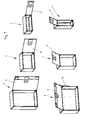
- FIGS. 6 and 7 show different arrangements and orientations of the housing 1, as in FIG. 1 are shown.
- FIG. 6 shows the case here in the closed position while FIG. 7 show the housing 1 in the open position.
- FIGS. 6 and 7 in the upper row the housing according to the FIG. 1 are aligned so that the doors 5 are posted on the right side wall 2 here.
- the lower row shows the housing 1 arranged rotated by 90 degrees, so that the doors are pivotally arranged in the region of the then acting as a lid 3 part of the housing 1.
- FIG. 7 shows the housing 1 in the open position and it is in this regard to the description of the FIGS. 1 . 2 and 6 directed.
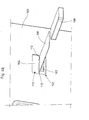
- a supporting element 21 is provided, which secures the door 5 in the open state against falling, so that the insertion of goods in the housing 1 here at the same time not unreal supporting the Door 5 can be made relative to the housing 1.
- the support member 21 may be formed, for example, as a gas spring. However, it can be provided here a closely wound coil spring which stretches when opening the door 5 and which is pivotable when closing the door 5, as a rule is kinked.
- a corresponding support member 21 and in the smaller housing 1 as shown in the lower row of FIG. 7 be provided on the right.
- FIG. 8 shows three different ways of securing a housing 1 in the masonry of a building.
- a separately shown, U-shaped angle provided, which is screwed on the wall side, wherein the width of the support frame 22 coincides with the width of the housing 1.
- the housing 1 is placed on the support frame 20 and the door 5 open via the interior, that is connected via the bottom 4 to the support frame 22, in particular screwed.
- the left picture in FIG. 8 shows an alternative embodiment in which the housing 1 is supported on two triangular angle elements 23.
- the angle elements 23 are screwed to the masonry of the building.
- the distance between the two angle elements 23 corresponds to a predetermined in the bottom 4 of the housing 1 hole pattern, which serves to receive screws with which the housing 1 with the angle elements 23 is connectable.
- these screws are designed such that they are not manipulated from outside the interior 6 of the housing 1, for example, that they offer no tool approach in the region of their abutting the angle element 23 head and the connection is made by screwed onto threaded sections nuts in the interior 6 of the housing 1 are arranged.
- FIG. 8 shows in FIG. 8 a support plate 24 which can be screwed to a building wall, wherein the support plate 24 is then screwed on already pre-assembled screw with the rear wall 8 of the housing 1.
- the support plate 24 is arranged by Umbördelungen in the longitudinal edge region partially at a distance from the building wall, so that these flanged portions are inserted into corresponding receptacles of the rear wall 8 of the housing 1.
- a screw lock can be provided, which in turn is accessible only via the interior 6 of the housing 1.
- the housing 1 of the devices described above consists of metal elements, for example, welded together, screwed or glued.
- the metal elements are formed as thin as possible, usually have a thickness of less than 1 mm. Nevertheless, in order to achieve sufficient stability of the housing, it is necessary to provide reinforcing elements.
- beading can be provided in the edge region of the metal elements, which form a stiffening of the metal elements like a bead.
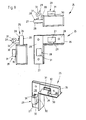
- reinforcing elements 25 are provided, as in the Figures 9 and 10 are shown in three side views, as well as in perspective view.
- each reinforcing element 25 is L-shaped and therefore has two legs 26, 27.
- the legs 26, 27 are T-shaped in cross-section, wherein the leg 27 has a lower thickness compared to the leg 26.
- Each leg 26, 27 has two mutually parallel front surfaces 28, on which articulation elements 29 are arranged, which serve to connect the housing 1 with the pivotally hinged door 5.
- the hinge elements 29, for example, intervene in the interruptions 20, as in FIG. 5 are shown.
- Each Ankenkelement 29 consists of an L-shaped web 30, which is on the one hand connected to a front surface 28 of the reinforcing member 25 and on the other hand has a hollow cylindrical portion 31 at its free end, said portion 31 is formed with a bore 32.
- the holes 32 in the two coupling elements 29 of a reinforcing element 25 are thus aligned with their axes parallel to the front surfaces 28 and thus to the legs 26 and 27 and beyond at right angles to each other.
- FIG. 10 differs from the embodiment according to FIG. 9 in that the articulation elements 29 are arranged on both sides of each web 26 or 27, so that in this way the usability of corresponding reinforcing elements 25 and thus the articulation of the door 5 on the housing 1 is made further variable.
- the reinforcing element 25 may be made of metal and / or tough hard plastic.
- the connection of the reinforcing element 25 to the housing 1 is screwed, welding or gluing.
- the closable opening of the housing 1 is surrounded by a surrounding frame.
- This peripheral frame may be a hindrance to the removal of a stored in the housing object, for example, a package or the like.
- the object received by the housing 1 substantially corresponds in its dimensions to the clear width of the opening which can be closed by the door of the housing 1.
- the object can namely by the opening are passed through into the interior of the housing 1.
- the object to be guided out of the housing 1 is to be grasped. If the object corresponds substantially to the clear width of the housing opening, the hands grasping the object can not be guided through the housing opening together with the object.
- the opening circumferentially limiting frame is simply in the way and there is a risk of finger and / or Handquetschungen or injuries.
- the peripheral frame may also be equipped with projections which reduce the clear opening size. It is thus achieved a reduction in the size of the opening with the advantage that a projecting into the clear opening projections corresponding gap remains, which is also available in case of emptying for a user for handrail feedthrough.
- the configuration of the above-described projections thus serves to create a circumferential gap area on the projections, which remains in the intended use case between the opening bounding peripheral frame on the one hand and an object to be passed through the opening on the other. This gap area serves a user in particular for hand-held passage in the case of the housing emptying.
- the closing device 7 also called locking system, consists of an RFID transponder lock and RFID tags, which authorize the opening of the lock.
- the shape of the RFID tags (check card format, keyfob / key fob, Disctag, Smartlabel, ...) can be chosen freely.
- the exclusivity of the locking system lies with the operator.
- RFID tags laminated reusable tags are provided. These can therefore - also in the interest of environmental compatibility - be reused. It will in particular laminated RFID tags according to ISO 15693 / 14443A proposed, as they have a high security and a robust reading behavior even with free weathering.
- one-way tags can be used. However, there is a possibility that malfunctions may occur due to moisture or buckling of the paper base support.
- the housing On the inside of the housing 1, also called postbox, there is a compartment in which the user or end customer inserts his end-user RFID tag after opening the box. Here it is automatically checked whether the inserted tag is also the "correct" end customer RFID tag. If it is not the right day or is not even inserted, a temporary acoustic alarm is triggered.
- the query of the storage compartment can be subsequently deactivated.
- the postboxes can be assigned by the operator district IDs, so that all boxes in a district have an identical ID.
- the deliverer RFID tag Via a programming station with PC software, the deliverer RFID tag can be unlocked for a specific district.
- the delivery tag RFID is therefore valid for only one district, so that only postboxes in this district can be opened with this tag. A subsequent restructuring of the districts is possible without any problems.
- the life of the battery and lock at approximately 400 operations per year is at least 10 years. At the end of the service life of the battery, this is visually or acoustically displayed to the deliverer when opening the postbox. The long period between two battery changes is possible by using a special battery.
- the permissible operating temperature range is between -40 ° C and + 60 ° C.
- the postbox system has no parts protruding on the outside of the door. This makes it vandalism-proof.
- the deliverer opens the postbox with the deliverer RFID tag, inserts one or more parcels and programs an end customer RFID tag into the postbox. He then throws this into the home mailbox of the end customer together with a notification stating the number of the postbox.
- the end customer opens the box once with the end customer RFID tag, places it in the compartment located on the inside of the door and then closes and locks the postbox. After locking, the tag loses its validity for this box. This also applies to several broadcasts in a box. Precautions have been taken that the end user locks the postbox after removal, so improper use is unlikely.
- Opening operations by deliverers or end customers can be logged in the electronics and, if necessary, e.g. be read out with a mobile barcode terminal for an additional charge.
- the device in particular the postbox is equipped with a stationary bar code reader.
- the stationary bar code reader can be arranged in the region of the door.
- the stationary bar code reader can be interchangeably arranged on the device.
- the stationary barcode reader can but also be arranged captive on the device integrated, in particular be integrated into the device.
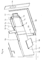
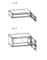
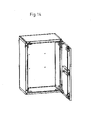
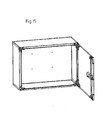
- FIG. 11 shows further embodiments of the device 1 according to the invention, which can also be referred to as a postbox.
- the postboxes are made of angled sheets.
- the individual parts are, depending on the size, connected by spot welding, rivets or screws. To increase the stability stiffening elements can be used.
- the postboxes are made of galvanized sheet steel.
- the postboxes may also be formed of a different material, e.g. Stainless steel.
- the material thickness depends on the application:
- the door is manually closed by the user. It can be provided an inside unlocking.
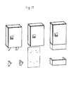
- Fig. 17 shows.
- the different postboxes are manufactured in modular construction. By using largely the same components an economical production is given.
- the postboxes can be delivered individually or in defined modules.
- the postboxes can be mounted next to each other, one above the other or on the back. Depending on the situation, the postboxes can also be mounted vertically or horizontally.
- attachment points are marked and can be drilled out precisely depending on the situation. If desired, these mounting holes can be pre-punched and closed with sealing plugs.
- the postboxes or systems are easy and quick to assemble.
- the hinges are designed for at least 440 operations (opening / closing) in the year.
- the construction is designed for a service life of at least 10 years.
- a logo can be visibly attached to the box.
- the box numbering can be done by means of number stickers.
- the postboxes can be factory-equipped to accommodate an individual numbering system. It can also be used plastic windows in which a labeling field is inserted from the inside.
- a powder coating or an anti-graffiti powder coating can be carried out.
- a high quality powder coating is preferable.
- the deliverer uses a PC with a programming station to release his deliverer RFID tag for a specific district and the maximum number of delivery openings to be made on this day.
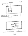
- the deliverer holds the delivery tag ( Fig. 18 ) to the sensor field of the postbox and actuates the switch on the sensor field.
- An LED or a buzzer indicates whether the postbox is free (eg a short light / buzzer) or occupied (eg once a long light / buzzer). If the box is free, the deliverer can now open the box over the slider in the recessed grip, if not, the deliverer can not open the box.
- the deliverer closes the postbox and holds the end customer RFID tag to the sensor field. By pressing the switch, the end customer RFID tag is programmed into the electronics.
- the deliverer now notes the number of the postbox on a notification and throws it together with the end customer RFID card in the home mailbox of the end customer.
- the end user removes the notification together with the end customer RFID tag from his home mailbox. He holds the end user RFID tag to the sensor field of the postbox noted on the notification and operates the switch on the sensor field.
- the LED indicates whether the card is authorized to open (eg two short flashes / buzzing) or whether it is not authorized to open (eg two long lights / buzzing). If the card is open, the end customer can now open the postbox and remove the package. Now the end customer deposits the end customer RFID tag ( Fig. 19 ) in the compartment located on the inside of the door, closes and locks the postbox. The validity of the end customer RFID tag expires automatically. The deliverer can remove and reuse the end-user RFID tag the next time the postbox is opened.
- An empty postbox can only be opened with a deliverable RFID tag valid for this district.
- An occupied postbox can only be opened with the end customer RFID tag previously programmed by the mail carrier. On request is a Reopening with the delivery RFID tag is only possible if it has been previously reinitialized. If the end customer does not pick up the package and therefore does not open the postbox, the previously programmed end customer RFID tag automatically expires after being opened by the deliverer , Carrier RFID tags have a limited validity.
- a delivery tag is only valid for a specific district. Furthermore, the card is unlocked in the morning for the maximum number of delivery openings to be made for this day. Thereafter, the day at the programming station for a particular district and a maximum number of delivery openings must be reinitialized. This ensures that stolen / lost RFID tags can not be used.
- End user RFID tags can only open a particular postbox once before they need to be reprogrammed.
- the user data is preferably AES-encrypted filed to prevent counterfeiting.
Landscapes
- Engineering & Computer Science (AREA)
- Food Science & Technology (AREA)
- Lock And Its Accessories (AREA)
Applications Claiming Priority (4)
| Application Number | Priority Date | Filing Date | Title |
|---|---|---|---|
| DE202011004756 | 2011-04-04 | ||
| DE202011005687 | 2011-04-28 | ||
| DE202011102418 | 2011-06-22 | ||
| DE202011104288 | 2011-08-12 |
Publications (2)
| Publication Number | Publication Date |
|---|---|
| EP2508108A2 true EP2508108A2 (fr) | 2012-10-10 |
| EP2508108A3 EP2508108A3 (fr) | 2013-01-09 |
Family
ID=46025460
Family Applications (1)
| Application Number | Title | Priority Date | Filing Date |
|---|---|---|---|
| EP12163206A Withdrawn EP2508108A3 (fr) | 2011-04-04 | 2012-04-04 | Dispositif destiné à la livraison de marchandises |
Country Status (1)
| Country | Link |
|---|---|
| EP (1) | EP2508108A3 (fr) |
Cited By (1)
| Publication number | Priority date | Publication date | Assignee | Title |
|---|---|---|---|---|
| EP2862485A1 (fr) * | 2013-10-17 | 2015-04-22 | Burg-Wächter Kg | Dispositif de dépôt et/ou de retrait de marchandises |
Citations (1)
| Publication number | Priority date | Publication date | Assignee | Title |
|---|---|---|---|---|
| DE10148300B4 (de) | 2001-08-29 | 2009-06-18 | Burg-Wächter Kg | Verfahren zur Zustellung von insbesondere großvolumigen Waren und Vorrichtung zur Zustellung von Waren |
Family Cites Families (2)
| Publication number | Priority date | Publication date | Assignee | Title |
|---|---|---|---|---|
| GB2370378B (en) * | 2000-08-25 | 2005-03-23 | Bearbox Com Ltd | Secure unattended delivery system |
| GB2425206B (en) * | 2005-04-14 | 2007-08-01 | Robert Grayson | Secure delivery of goods |
-
2012
- 2012-04-04 EP EP12163206A patent/EP2508108A3/fr not_active Withdrawn
Patent Citations (1)
| Publication number | Priority date | Publication date | Assignee | Title |
|---|---|---|---|---|
| DE10148300B4 (de) | 2001-08-29 | 2009-06-18 | Burg-Wächter Kg | Verfahren zur Zustellung von insbesondere großvolumigen Waren und Vorrichtung zur Zustellung von Waren |
Cited By (1)
| Publication number | Priority date | Publication date | Assignee | Title |
|---|---|---|---|---|
| EP2862485A1 (fr) * | 2013-10-17 | 2015-04-22 | Burg-Wächter Kg | Dispositif de dépôt et/ou de retrait de marchandises |
Also Published As
| Publication number | Publication date |
|---|---|
| EP2508108A3 (fr) | 2013-01-09 |
Similar Documents
| Publication | Publication Date | Title |
|---|---|---|
| EP1353588B1 (fr) | Dispositif et procede de remise automatique de marchandises | |
| EP3046447B1 (fr) | Unité de verrouillage, boîtier avec unité de verrouillage et procédé de déverrouillage d'une ou de plusieurs portes du boîtier | |
| EP2862485B1 (fr) | Dispositif de dépôt et/ou de retrait de marchandises | |
| EP2991045B1 (fr) | Système de distribution intelligent | |
| DE112016004841T5 (de) | Elektronisches Schloss und elektronisches Verriegelungssystem für Möbel, Schränke oder Schliessfächer | |
| EP3002738B1 (fr) | Dispositif de securisation et recipient de securite pour pieces d'emballage | |
| WO2014048412A2 (fr) | Système d'armoire | |
| EP2947612A1 (fr) | Système pour le protection de paquets | |
| DE102004013369A1 (de) | Elektronisches Kontroll-System | |
| DE60224519T2 (de) | Einrichtung zum lagern und disponieren von artikeln zum zurückzug | |
| EP1636770A1 (fr) | Distributeur d'objets | |
| EP2508108A2 (fr) | Dispositif destiné à la livraison de marchandises | |
| DE202007000731U1 (de) | Zustell- und/oder Lieferantenbox und deren Schließvorrichtung | |
| DE102009040426B4 (de) | Zugangsvorrichtung, insbesondere für eine Müllentsorgungseinrichtung | |
| EP3340197A1 (fr) | Système de distribution d'articles et distributeur d'articles | |
| DE102004055979B4 (de) | Verschlusseinheit zur Verwendung an oder in Wertbehältern, Waren- und Dienstleistungsautomaten oder dergleichen | |
| EP3473142A1 (fr) | Colis box pour déstinataires de colis délivrés | |
| DE19803707A1 (de) | Verfahren und Vorrichtung zum Empfang von Lieferungen | |
| DE10101680B4 (de) | Vorrichtung zur Zustellung und vorübergehenden Verwahrung von Gegenständen | |
| DE10246649B4 (de) | Vorrichtung für die Aufnahme und Entnahme von Sendungen aller Art und Verfahren hierfür | |
| DE10023520A1 (de) | Anordnung zur Anlieferung und Versendung von Waren | |
| DE10305333A1 (de) | Verfahren zur Lieferung und Zustellung von Sendungen mit einer Waren- und Paket-Depot-Anlage | |
| EP1025027B1 (fr) | Procede et systeme pour verifier la livraison correcte d'articles a livrer mobiles a des unites de stockage | |
| DE60037029T2 (de) | Sichere warenabgabevorrichtung und verfahren | |
| DE19919678C2 (de) | Müllschleuse für Gebäude mit miteinander verbundenen und in wenigstens einem Raum endenden Schächten zum abrechenbaren Aufnehmen und Transportieren des Mülls |
Legal Events
| Date | Code | Title | Description |
|---|---|---|---|
| PUAI | Public reference made under article 153(3) epc to a published international application that has entered the european phase |
Free format text: ORIGINAL CODE: 0009012 |
|
| AK | Designated contracting states |
Kind code of ref document: A2 Designated state(s): AL AT BE BG CH CY CZ DE DK EE ES FI FR GB GR HR HU IE IS IT LI LT LU LV MC MK MT NL NO PL PT RO RS SE SI SK SM TR |
|
| AX | Request for extension of the european patent |
Extension state: BA ME |
|
| PUAL | Search report despatched |
Free format text: ORIGINAL CODE: 0009013 |
|
| AK | Designated contracting states |
Kind code of ref document: A3 Designated state(s): AL AT BE BG CH CY CZ DE DK EE ES FI FR GB GR HR HU IE IS IT LI LT LU LV MC MK MT NL NO PL PT RO RS SE SI SK SM TR |
|
| AX | Request for extension of the european patent |
Extension state: BA ME |
|
| RIC1 | Information provided on ipc code assigned before grant |
Ipc: A47G 29/14 20060101AFI20121130BHEP |
|
| 17P | Request for examination filed |
Effective date: 20130703 |
|
| RBV | Designated contracting states (corrected) |
Designated state(s): AL AT BE BG CH CY CZ DE DK EE ES FI FR GB GR HR HU IE IS IT LI LT LU LV MC MK MT NL NO PL PT RO RS SE SI SK SM TR |
|
| STAA | Information on the status of an ep patent application or granted ep patent |
Free format text: STATUS: EXAMINATION IS IN PROGRESS |
|
| 17Q | First examination report despatched |
Effective date: 20170904 |
|
| STAA | Information on the status of an ep patent application or granted ep patent |
Free format text: STATUS: THE APPLICATION HAS BEEN WITHDRAWN |
|
| 18W | Application withdrawn |
Effective date: 20190227 |