EP2508143B1 - Ultraschallsaugvorrichtung - Google Patents
Ultraschallsaugvorrichtung Download PDFInfo
- Publication number
- EP2508143B1 EP2508143B1 EP11795697.9A EP11795697A EP2508143B1 EP 2508143 B1 EP2508143 B1 EP 2508143B1 EP 11795697 A EP11795697 A EP 11795697A EP 2508143 B1 EP2508143 B1 EP 2508143B1
- Authority
- EP
- European Patent Office
- Prior art keywords
- ultrasound
- section
- image
- mist
- driving signal
- Prior art date
- Legal status (The legal status is an assumption and is not a legal conclusion. Google has not performed a legal analysis and makes no representation as to the accuracy of the status listed.)
- Active
Links
Images


Classifications
-
- A—HUMAN NECESSITIES
- A61—MEDICAL OR VETERINARY SCIENCE; HYGIENE
- A61B—DIAGNOSIS; SURGERY; IDENTIFICATION
- A61B17/00—Surgical instruments, devices or methods
- A61B17/32—Surgical cutting instruments
- A61B17/320068—Surgical cutting instruments using mechanical vibrations, e.g. ultrasonic
-
- A—HUMAN NECESSITIES
- A61—MEDICAL OR VETERINARY SCIENCE; HYGIENE
- A61B—DIAGNOSIS; SURGERY; IDENTIFICATION
- A61B90/00—Instruments, implements or accessories specially adapted for surgery or diagnosis and not covered by any of the groups A61B1/00 - A61B50/00, e.g. for luxation treatment or for protecting wound edges
- A61B90/36—Image-producing devices or illumination devices not otherwise provided for
-
- A—HUMAN NECESSITIES
- A61—MEDICAL OR VETERINARY SCIENCE; HYGIENE
- A61B—DIAGNOSIS; SURGERY; IDENTIFICATION
- A61B17/00—Surgical instruments, devices or methods
- A61B2017/00017—Electrical control of surgical instruments
- A61B2017/00022—Sensing or detecting at the treatment site
-
- A—HUMAN NECESSITIES
- A61—MEDICAL OR VETERINARY SCIENCE; HYGIENE
- A61B—DIAGNOSIS; SURGERY; IDENTIFICATION
- A61B17/00—Surgical instruments, devices or methods
- A61B2017/00017—Electrical control of surgical instruments
- A61B2017/00022—Sensing or detecting at the treatment site
- A61B2017/00057—Light
-
- A—HUMAN NECESSITIES
- A61—MEDICAL OR VETERINARY SCIENCE; HYGIENE
- A61B—DIAGNOSIS; SURGERY; IDENTIFICATION
- A61B17/00—Surgical instruments, devices or methods
- A61B2017/00017—Electrical control of surgical instruments
- A61B2017/00137—Details of operation mode
-
- A—HUMAN NECESSITIES
- A61—MEDICAL OR VETERINARY SCIENCE; HYGIENE
- A61B—DIAGNOSIS; SURGERY; IDENTIFICATION
- A61B17/00—Surgical instruments, devices or methods
- A61B2017/00831—Material properties
- A61B2017/00902—Material properties transparent or translucent
-
- A—HUMAN NECESSITIES
- A61—MEDICAL OR VETERINARY SCIENCE; HYGIENE
- A61B—DIAGNOSIS; SURGERY; IDENTIFICATION
- A61B17/00—Surgical instruments, devices or methods
- A61B17/32—Surgical cutting instruments
- A61B17/320068—Surgical cutting instruments using mechanical vibrations, e.g. ultrasonic
- A61B2017/320069—Surgical cutting instruments using mechanical vibrations, e.g. ultrasonic for ablating tissue
-
- A—HUMAN NECESSITIES
- A61—MEDICAL OR VETERINARY SCIENCE; HYGIENE
- A61B—DIAGNOSIS; SURGERY; IDENTIFICATION
- A61B17/00—Surgical instruments, devices or methods
- A61B17/32—Surgical cutting instruments
- A61B17/320068—Surgical cutting instruments using mechanical vibrations, e.g. ultrasonic
- A61B2017/32007—Surgical cutting instruments using mechanical vibrations, e.g. ultrasonic with suction or vacuum means
-
- A—HUMAN NECESSITIES
- A61—MEDICAL OR VETERINARY SCIENCE; HYGIENE
- A61B—DIAGNOSIS; SURGERY; IDENTIFICATION
- A61B90/00—Instruments, implements or accessories specially adapted for surgery or diagnosis and not covered by any of the groups A61B1/00 - A61B50/00, e.g. for luxation treatment or for protecting wound edges
- A61B90/36—Image-producing devices or illumination devices not otherwise provided for
- A61B2090/364—Correlation of different images or relation of image positions in respect to the body
-
- A—HUMAN NECESSITIES
- A61—MEDICAL OR VETERINARY SCIENCE; HYGIENE
- A61B—DIAGNOSIS; SURGERY; IDENTIFICATION
- A61B2218/00—Details of surgical instruments, devices or methods for transferring non-mechanical forms of energy to or from the body
- A61B2218/001—Details of surgical instruments, devices or methods for transferring non-mechanical forms of energy to or from the body having means for irrigation and/or aspiration of substances to and/or from the surgical site
- A61B2218/002—Irrigation
-
- A—HUMAN NECESSITIES
- A61—MEDICAL OR VETERINARY SCIENCE; HYGIENE
- A61B—DIAGNOSIS; SURGERY; IDENTIFICATION
- A61B2218/00—Details of surgical instruments, devices or methods for transferring non-mechanical forms of energy to or from the body
- A61B2218/001—Details of surgical instruments, devices or methods for transferring non-mechanical forms of energy to or from the body having means for irrigation and/or aspiration of substances to and/or from the surgical site
- A61B2218/007—Aspiration
-
- A—HUMAN NECESSITIES
- A61—MEDICAL OR VETERINARY SCIENCE; HYGIENE
- A61B—DIAGNOSIS; SURGERY; IDENTIFICATION
- A61B90/00—Instruments, implements or accessories specially adapted for surgery or diagnosis and not covered by any of the groups A61B1/00 - A61B50/00, e.g. for luxation treatment or for protecting wound edges
- A61B90/36—Image-producing devices or illumination devices not otherwise provided for
- A61B90/361—Image-producing devices, e.g. surgical cameras
Definitions
- the present invention relates to an ultrasound suction system that performs suction using ultrasound.
- an ultrasound suction apparatus or an ultrasound suction system that gives ultrasound vibration energy to a treatment target living tissue, fragments a fragile tissue with ultrasound vibration and sucks the fragile tissue, and exposes an abundantly elastic tissue such as a blood vessel without fragmenting the tissue.
- the fragile tissue is emulsified and fluid is supplied to a surface of the treatment target living tissue such that fragmented tissue pieces can be smoothly sucked. Therefore, when the ultrasound vibration energy is given to the treatment target living tissue, since the ultrasound vibration energy is given to the fluid as well, in some cases, the fluid changes to mist and deteriorates an observation function from an observation window of the endoscope.
- a gas supply and suction control system disclosed in Japanese Patent Application Laid-Open Publication No. 11-155869 as a first prior example related to the deterioration in the observation function performs, on the basis of a stop signal for output by a high-frequency cauterization apparatus or an ultrasound coagulation dissection apparatus, control for performing suction by sucking means with a delay of a predetermined time together with pressurization because smoke or mist caused by the high-frequency cauterization apparatus or the ultrasound coagulation dissection apparatus prevents observation by an endoscope. According to the control, the smoke or the mist is sucked and removed even after the stop of the output of the high-frequency cauterization apparatus or the like.
- Japanese Patent Application Laid-Open Publication No. 2007-296002 as a second prior example discloses contents for supplying pressurized gas to an observation window because smoke or mist caused by a high-frequency cauterization apparatus adheres to the observation window at a distal end of an endoscope and deteriorates an observation field of view, feeding CO2 gas as the pressurized gas along a surface of the observation window, and forming a fluid curtain to prevent the smoke or the mist from reaching the surface of the observation window.
- an ultrasound suction system cannot ensure an observation field of view to be in a clear state by means of a fluid curtain.
- the present invention was made in view of the above-mentioned points, and an objective of the present invention is to provide an ultrasound suction system capable of controlling an ultrasound output or fluid in accordance with an amount of generation of mist by means of an observation function of an endoscope and supporting a surgeon to conduct a processing.
- An ultrasound suction system includes the features of claim 1.
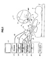
- an ultrasound suction system 1 applies, using ultrasound vibration energy (abbreviated as ultrasound vibration), treatment to, for example, a living tissue of a diseased part 5 set as a treatment target in an abdomen 4 of a patient 3 lying on a bed 2.
- ultrasound vibration energy abbreviated as ultrasound vibration
- the ultrasound suction system 1 includes an ultrasound driving signal generating unit 6 that generates an ultrasound driving signal for generating ultrasound vibration.
- the ultrasound driving signal generating unit 6 outputs the generated ultrasound driving signal to an ultrasound suction probe 8 functioning as an ultrasound suction section via a signal cable 7.
- the ultrasound suction probe 8 incorporates an ultrasound transducer 9 functioning as an ultrasound generating section that generates ultrasound vibration by being applied with the ultrasound driving signal from the ultrasound driving signal generating unit 6 via the signal cable 7.
- the ultrasound transducer 9 With the ultrasound transducer 9, the generated ultrasound vibration is transmitted to a distal end portion 11 of the ultrasound suction probe 8 via a transmission pipe 10 functioning as a vibration transmitting section that transmits the ultrasound vibration.
- a surgeon brings the distal end portion 11 into contact with a surface of the living tissue of the diseased part 5, whereby the ultrasound vibration is given to the living tissue of the diseased part 5 and a fragile living tissue portion such as a fat tissue in the living tissue is fragmented. Further, fragmented living tissue pieces are emulsified under presence of fluid (specifically, a physiological salt solution) supplied to a living tissue surface explained below.
- fluid specifically, a physiological salt solution
- the ultrasound suction system 1 includes a water supply and suction unit 12 included in a fluid supplying section such that the fragmented living tissue pieces can be smoothly removed by suction.
- a water supply device 41 in the water supply and suction unit 12 supplies the physiological salt solution (simply abbreviated as water) serving as fluid via a water supply tube 13a provided in the ultrasound suction probe 8.
- a suction device 42 sucks the fragmented living tissue pieces as emulsion and the water via a suction tube 13b provided in the ultrasound suction probe 8.
- the ultrasound suction system 1 includes an endoscope 14 that optically observes the diseased part 5, the distal end side of the ultrasound suction probe 8, and the like, a processor 17 that performs signal processing for an image pickup device 16 included in an image pickup section 15 (shown in Fig. 2 ) functioning as an observing section provided in the endoscope 14, and a light source unit 18 for illuminating an image pickup range in which an image is picked up by the image pickup section 15.
- a light guide cable 19 extended from the endoscope 14 is connected to the light source unit 18.
- a signal cable 20 extended from the endoscope 14 is connected to the processor 17.
- An image signal (a video signal) generated by image processing by the processor 17 is outputted to a monitor 21 functioning as image display means.
- An image picked up by the image pickup section 15 is displayed on a display surface of the monitor 21 as an endoscope image.
- the endoscope 14 is inserted into the abdomen 4 via a trocar 22.
- the ultrasound suction probe 8 is also inserted into the abdomen 4 actually via a trocar.
- a pneumoperitoneum tube 23 connected to the trocar 22 is connected to a pneumoperitoneum unit 24.
- the pneumoperitoneum unit 24 supplies gas for pneumoperitoneum into the abdomen 4 via the pneumoperitoneum tube 23 by a gas supply and gas suction device included in a pneumoperitoneum device 25, inflates an inside of the abdomen 4 with the gas, changes the inside of the abdomen to a state in which observation and treatment can be easily performed.
- the pneumoperitoneum device 25 can also suck the gas in the abdomen 4 via the pneumoperitoneum tube 23. By sucking the gas, the pneumoperitoneum device 25 can quickly set the inside of the abdomen 4 to predetermined pressure.
- Operation of gas supply and gas suction of the pneumoperitoneum device 25 is controlled by a pneumoperitoneum controller 26.
- the pneumoperitoneum device 25 includes a pressure sensor 25a such that pressure control can be performed by the pneumoperitoneum controller 26. Atmospheric pressure in the abdomen 4 can be kept constant according to pressure information by the pressure sensor 25a.
- a foot switch 28 is provided as a user interface with which a user such as a surgeon applies instruction operation to the ultrasound driving signal generating unit 6, the water supply and suction unit 12, the light source unit 18, the pneumoperitoneum unit 24, and the like.
- an ultrasound switch 28a as an instruction operation switch for applying instruction operation for generation (ON) and stop (OFF) of an ultrasound driving signal to the ultrasound driving signal generating unit 6 is provided.
- a gas supply and water supply switch for applying instruction operation for ON/OFF of gas supply and water supply to the gas supply and water supply unit 55
- a pneumoperitoneum switch for performing instruction operation for ON/OFF of pneumoperitoneum (gas supply and gas suction) of the pneumoperitoneum unit 24, and the like may be provided.
- Fig. 2 shows main components of the units in Fig. 1 .
- the ultrasound suction probe 8 includes a slender outer pipe (or sheath) 31 and the transmission pipe 10 that is coaxially inserted through the outer pipe 31 and transmits ultrasound.
- a gripping portion 32 expanded in diameter is provided on a proximal end side in the outer pipe 31.
- the ultrasound transducer 9 is arranged on an inside of the gripping portion 32.
- the ultrasound transducer 9 is provided in a ring shape, for example, near a rear end of the transmission pipe 10. Ultrasound vibration by the ultrasound transducer 9 is transmitted to the distal end portion 11 by the transmission pipe 10. As indicated by an arrow in Fig. 2 , the distal end portion 11 ultrasonically vibrates in an axis direction thereof.
- An internal space of the transmission pipe 10 forms a suction conduit.
- a rear end of the transmission pipe 10 is connected to the water supply and suction unit 12 via the suction tube 13b.
- the water supply tube 13a is connected to a first water supply pipe 33a provided on a proximal end side of the ultrasound suction probe 8.
- the first water supply pipe 33a communicates with a second water supply pipe 33b between the transmission pipe 10 and the outer pipe 31 halfway in the first water supply pipe 33a.
- the distal end of the outer pipe 31 has a tapered-off shape and opens slightly behind the distal end of the transmission pipe 10. As indicated by an arrow, water is supplied from a ring-like opening portion on the outer side of the transmission pipe 10.
- the distal end of the outer pipe 31 has the tapered-off shape but is not limited to the tapered-off shape.
- the distal end side of the outer pipe 31 has a circular tube shape.
- the distal end opening of the transmission pipe 10 is a suction port 10a. Fragmented living tissue pieces and the like are sucked from the suction port 10a while being mixed in the water supplied as indicated by the arrow.
- Fig. 1 in a circular enlarged view, a state in which treatment is applied to a living tissue is shown.
- the ultrasound driving signal generating unit 6 includes an oscillator 36 that generates an AC oscillation signal, an output circuit 37 that amplifies the oscillation signal and insulates the oscillation signal and outputs the oscillation signal as an ultrasound driving signal, and an oscillation and output controller 38 that performs control of oscillation and oscillation stop by the oscillator 36 and control of output from the output circuit 37.
- the ultrasound transducer 9 of the ultrasound suction probe 8 is applied with an ultrasound driving signal from the output circuit 37 via the signal cable 7.
- the ultrasound transducer 9 generates ultrasound or generates ultrasound vibration.
- the output circuit 37 incorporates an amplifier or attenuator 37a that changes a current value of the ultrasound driving signal outputted to the ultrasound transducer 9.
- An output controller of the oscillation and output controller 38 controls the amplifier or attenuator 37a to perform control including a reduction in the output of the ultrasound driving signal.
- the output controller may perform the control including a reduction in the output of the ultrasound driving signal by changing amplitude of the ultrasound driving signal.
- the foot switch 28 is connected to the oscillation and output controller 38.
- the surgeon can operate the foot switch 28 and perform an output instruction, an output stop (oscillation stop) instruction, and the like for the ultrasound driving signal.
- the water supply and suction unit 12 includes the water supply device 41 that performs water supply and the suction device 42 that performs suction as explained above and a water supply and suction controller 43 that controls operation of the water supply device 41 and the suction device 42.
- the water supply device 41 is connected to the water supply tube 13a and supplies water to the water supply pipes 33a and 33b side of the ultrasound suction probe 8 via the water supply tube 13a.
- the suction device 42 is connected to the suction tube 13b and sucks water from the suction port 10a at the distal end of the transmission pipe 10 via the transmission pipe 10 having a function of a suction conduit of the ultrasound suction probe 8 connected to the suction tube 13b.
- the endoscope 14 includes an elongated insertion portion 45 and a gripping portion 46 provided at a rear end of the insertion portion 45.
- An illuminating window and an observation window are provided at a distal end portion 47 of the insertion portion 45.
- An illumination lens 48 is attached to the illuminating window to form an illumination section.
- An objective lens 49 is attached to the observation window.
- the image pickup device 16 is arranged at an image-forming position of the objective lens 49 to form the image pickup section 15 functioning as the observing section.
- the nozzle 50 Near the objective lens 49 that forms an observation field of view by the observing section, the nozzle 50, a spout port of which faces the objective lens 49, is arranged.
- Illuminating light from the light source unit 18 is transmitted by a light guide 51 inserted through the endoscope 14 and emitted from an end of the light guide 51 via the illumination lens 48.
- An optical image of the diseased part 5 or the like illuminated by the illuminating light from the illumination lens 48 is formed by the objective lens 49 on the image pickup device 16 arranged at an image-forming position of the objective lens 49.
- the light source unit 18 collects, with a lens 54, illuminating light generated by a light source lamp 53 and makes the illuminating light incident on a proximal end of the light guide 51.
- the light source unit 18 includes a gas supply and water supply unit 55 that supplies gas and water. Operation by the gas supply and water supply unit 55 is controlled by a gas supply and water supply controller (abbreviated as controller) 56.
- controller gas supply and water supply controller
- the gas supply and water supply unit 55 is connected to a gas supply and water supply tube 58, which is provided in the endoscope 14, via a gas supply and water supply tube 57.
- the gas supply and water supply unit 55 spouts gas and water from the nozzle 50 included in the fluid spouting section provided at a distal end of the gas supply and water supply tube 58 to an outer surface of the objective lens 49 of the observation window. According to the spouting operation, deposit adhering to the outer surface is removed to make it possible to keep the observation window in a clean state, i.e., secure a satisfactory observation field of view.
- the fluid spouting section may be defined to include the nozzle 50 and the gas supply and water supply unit 55.
- the processor 17 to which the signal cable 20 is connected includes an image pickup device drive circuit (abbreviated as drive circuit) 61 connected to the image pickup device 16.
- the drive circuit 61 applies the image pickup device with a drive signal.
- the image pickup device 16 outputs, by being applied with the drive signal, an image signal obtained by photoelectrically converting an optical image formed on an image pickup surface.
- the image signal outputted from the image pickup device 16 is color-separated into image signals of color components by a color separation circuit 63 included in an image processing unit 62 in the processor 17 and then converted into digital image signals of the color components by an A/D converter 64 and temporarily recorded (stored) in a memory 65.
- the image signals of the color components recorded by the memory 65 are further subjected to image processing such as gamma correction by the image processing circuit 66.
- image processing such as gamma correction by the image processing circuit 66.
- a standard image signal is generated and outputted to the monitor 21. The surgeon performs treatment by the ultrasound suction probe 8 while observing, as an observed image, an endoscope image displayed on the monitor 21.
- the surgeon can fragment a fragile living tissue and efficiently suck water mixed with fragmented living tissue pieces (emulsion) with the ultrasound suction probe 8 while performing water supply and suction.
- emulsion fragmented living tissue pieces
- an observed image in which an image of a living tissue portion indicated by a sign Ia can be satisfactorily observed is obtained.
- the observed image changes to an observed image involving linear mist having high luminance such as fireworks or rain in the observed image Ia as schematically shown in Fig. 3B .
- an observed image in a state in which mist does not (substantially) occurs is acquired and a reference image serving as a reference is set in advance as explained below.
- a following observed image is compared with the reference observed image.
- a change equal to or larger than a predetermined value is detected, it is determined that the observed image is an observed image in which mist exceeding the predetermined value occurs.
- a mist determination signal corresponding to the occurrence of the mist exceeding the predetermined value is generated from a result of the determination.
- the image signals of the color components recorded in the memory 65 in the processor 17 are inputted to an image acquisition circuit 69 included in a mist determining and determination signal generating section 68.
- the image acquisition circuit 69 may acquire an image signal of one color component or may acquire plural image signals.
- a luminance signal Y may be generated from, for example, color signals of R, G, and B.
- the image acquisition circuit 69 may acquire the luminance signal Y.
- the image acquisition circuit 69 generates (an image signal of) a reference image for detecting occurrence of mist exceeding the predetermined value from the acquired image signals and acquires, in time series, observed images for which it is determined whether mist exceeding the predetermined value occurs.
- the image acquisition circuit 69 extracts, for example, an image portion of a predetermined region from an observed image picked up at the time (timing) when the ultrasound switch 28a is changed from OFF to ON from a state in which mist does not occur and records the image portion in a reference image memory 70 as a reference image.
- timing for recording (acquiring) the reference image As timing for recording (acquiring) the reference image as explained below, besides the time when the ultrasound switch 28a is turned on, arbitrary timing up to time when the ultrasound switch 28a is turned on or immediately after the ultrasound switch 28a is turned on may be set.
- a state up to the time when the ultrasound switch 28a is turned on or immediately after the ultrasound switch 28a is turned on is equivalent to a state at a time when the ultrasound transducer 9 is applied with an ultrasound driving signal, the ultrasound transducer 9 ultrasonically vibrates, and the ultrasound vibration is given to the distal end portion 11 of the ultrasound suction probe 8 via the transmission pipe 10 or immediately after the ultrasound vibration is given.
- An observed image (or an image portion of a predetermined region of the observed image) picked up in a state in which mist substantially does not occur from the time when the ultrasound vibration is given until immediately after the ultrasound vibration is given may be set as a reference image.
- a case of the timing when the ultrasound switch 28a is turned on equivalent to the time when the ultrasound vibration is given is mainly explained.
- the image acquisition circuit 69 extracts a part of an observed image of the same predetermined region from the memory 65 and outputs the part of the observed image to a comparison circuit 71.
- the comparison circuit 71 compares the reference image recorded in the reference image memory 70 and the observed image acquired by the image acquisition circuit 69 in the state in which the ultrasound switch 28a is turned on.
- the comparison circuit 71 outputs a comparison result to a determination circuit 72.
- the determination circuit 72 determines, from the comparison result by the comparison circuit 71, whether there is a change equal to or larger than a predetermined value and outputs a determination result to a controller 73 included in a control section. Only when the determination circuit 72 determines that there is a change equal to or larger than the predetermined value in the observed image in comparison with the reference image, the determination circuit 72 determines that mist exceeding the predetermined value occurs and outputs a mist determination signal.
- the controller 73 has a function of the control section for controlling, according to a determination result by the determination circuit 72, at least operation of the ultrasound driving signal generating unit 6 and the water supply and suction unit 12.
- the controller 73 performs control for causing the ultrasound driving signal generating unit 6 to stop or reduce the output of the ultrasound driving signal and performs control for causing the water supply and suction unit 12 to stop operation of water supply and suction or reduce an operation function (of water supply and suction).
- the controller 73 can control the sections in the processor 17 and, by sending control signals to the controllers 38, 43, 26, and 56 of the ultrasound driving signal generating unit 6, the water supply and suction unit 12, the pneumoperitoneum unit 24, the light source unit 18 included in the ultrasound suction system 1, can control operations of the units.
- the operation of the ultrasound driving signal generating unit 6, the water supply and suction unit 12, the pneumoperitoneum unit 24, and the light source unit 18 may be concentratedly controlled directly according to the control signals by the controller 73 not via the controllers 38, 43, 26, and 56.
- a setting section 74 sets a reference image and performs, besides determination of occurrence of mist exceeding the predetermined value, setting operation for an operation mode for determining whether deposit due to scattering of mist adheres to the outer surface of the object lens 49 and the objective lens 49 changes to a state of an unclear observation field of view as explained later.
- the user such as the surgeon can perform setting and selection of a reference image, selection of an operation mode, and the like from the setting section 74.
- a signal in the case of the setting and selection from the setting section 74 is inputted to the controller 73.
- the controller 73 performs setting and selection of a reference image and control of an operation mode according to the signal.
- An output mode setting section may be provided that selects and sets a continuous output mode for continuously outputting an ultrasound driving signal and an intermittent output mode for intermittently outputting an ultrasound driving signal when the ultrasound switch 28a is turned on.
- the ultrasound driving signal generating unit 6 may be caused to operate in the intermittent output mode as shown in a figure in a fourth embodiment explained later.
- Fig. 4 shows a more specific configuration example of the mist determining and determination signal generating section 68.
- Image signals of frames are read out from the memory 65 according to an address signal based on a clock from a clock circuit 69a included in the image acquisition circuit 69, outputted to the image processing circuit 66, and inputted to a gate 69c via a counter 69b.
- the gate 69c is open in a period corresponding to a predetermined region corresponding to a setting value set by the counter 69b.
- An image signal in that period is stored in the reference image memory 70 as a reference image via a switch 69d.
- a solid line in Fig. 5A indicates a scanning line Lh serving as the predetermined region.
- the image signal passes through the gate 69c in a period Th corresponding to the scanning line Lh.
- the predetermined region corresponding to one scanning line Lh is indicated by the solid line in Fig. 5A .
- the predetermined region may be set by plural scanning lines Lh as indicated by dotted lines.
- the predetermined region is not limited to the scanning line Lh in the horizontal direction. As indicated by an alternate long and two short dashes line, for example, the predetermined region for performing mist determination may be set in an image portion on a diagonal line Ld. Besides, the predetermined region may be set along the vertical direction.
- an image region may be divided into plural small regions Rs as shown in Fig. 9B .
- One or plural small regions Rs may be set as the predetermined region for performing mist determination.
- a predetermined period may be set instead of the predetermined region.
- a contact a is selected in a state in which an ultrasound ON signal by ON operation of the ultrasound switch 28a is not inputted.
- a contact b is selected when the ultrasound ON signal is inputted. Therefore, in a state in which the contact a is selected, the reference image of the reference image memory 70 is sequentially updated to new reference images.
- the ultrasound ON signal is generated, a part of an observed image acquired by the observing section at timing of the ultrasound ON signal is frozen in the reference image memory 70 as a reference image.
- the image signal from the memory 65 is inputted to the comparison circuit 71 in a predetermined horizontal period when the gate 69c is open.
- the image signal of the reference image recorded in the reference image memory 70 is also inputted to the comparison circuit 71 in synchronization with the open of the gate 69c.
- the comparison circuit 71 compares two image signals each inputted in synchronization with the predetermined period Th.
- the comparison circuit 71 performs comparison to determine whether an image signal of an observed image has a sufficiently high luminance value compared with a luminance value of the reference image rather than directly comparing luminance values of both the image signals.
- the comparison circuit 71 includes a comparator 71 a and a threshold setting device 71b (in Fig. 4 , simply abbreviated as threshold 71b stored therein). The same holds true concerning a threshold setting device 72c explained later.
- the comparator 71a compares a luminance value obtained by adding the threshold 71b (set by the threshold setting device 71b) to an image signal Ir of the reference image and an image signal of an observed image and outputs a comparison result to the determination circuit 72.
- an image signal Ira of the reference image set by adding a threshold Vth to the image signal of the reference image indicated by the solid line is indicated by a dotted line.
- a luminance value of the image signal substantially continuously changes. A value of the change is not so large in a short period.
- an image signal in a state in which mist exceeding the predetermined value occurs is an image signal Io involving pulses P in which the luminance value sharply changes in a pulse (or line) shape (because illuminating light is reflected by the mist) as shown in Fig. 5C .
- the mist exceeding the predetermined value occurs, it frequently occurs that plural pulses P are discretely involved, for example, on the scanning line Lh serving as the predetermined region.
- the determination circuit 72 counts, with a counter 72b, an output signal of the comparison circuit 71 in synchronization with a predetermined clock by a clock circuit 72a having a predetermined period. As explained above, since the mist occurs to increase the luminance value in a pulse shape, the determination circuit 72 counts, with the counter 72b, the output value using a clock C corresponding to width La slightly larger than average pulse width Lp of the luminance value (La>Lp).
- the determination circuit 72 determines, with a comparison circuit 72d, whether a count value of the counter 72b is larger than a threshold 72c. When the count value of the counter 72b is larger than the threshold 72c, the comparison circuit 72d outputs a mist determination signal to the controller 73 via an AND circuit 72e. In this way, it is possible to effectively determine a pulse-like image involving the pulses P, which is a characteristic of the mist, according to image processing based on an observed image.
- the ultrasound ON signal from the ultrasound switch 28a of the foot switch 28 is inputted to the AND circuit 72e. Only in a state in which the ultrasound ON signal is inputted, the determination circuit 72 generates the mist determination signal indicating determination of the occurrence of the mist exceeding the predetermined value.
- the controller 73 When the mist determination signal is inputted, the controller 73 generates a suppression signal for suppressing the occurrence of the mist.
- the controller 73 performs, according to the suppression signal, control for stopping or reducing generation of an ultrasound driving signal via the oscillation and output controller 38 of the ultrasound driving signal generating unit 6.
- the controller 73 performs, according to the suppression signal, control for stopping or reducing water supply of the water supply device 41 via the controller 43 of the water supply and suction unit 12.
- the generation of the ultrasound driving signal is stopped, whereby ultrasound vibration by the ultrasound transducer 9 is quickly stopped. Therefore, when the mist exceeding the predetermined value occurs, the occurrence of the mist is quickly reduced or stopped according to the stop of the ultrasound vibration.
- an output value of the ultrasound driving signal may be controlled to be reduced.
- a water supply amount may be controlled to be reduced.
- a suction amount may be controlled to be reduced.
- the ultrasound suction system 1 having the configuration explained above includes the ultrasound driving signal generating unit 6 functioning as an ultrasound driving signal generating section that generates an ultrasound driving signal and the ultrasound suction probe 8 in which the ultrasound transducer 9 functioning as the ultrasound generating section that generates ultrasound vibration energy according to application of the ultrasound driving signal and the suction port 10a for transmitting the ultrasound vibration energy generated by the ultrasound generating section to the distal end portion 11 and giving the ultrasound vibration energy to a treatment target living tissue from the distal end portion 11, fragmenting the living tissue, and sucking fragmented living tissue pieces are provided.
- the ultrasound driving signal generating unit 6 functioning as an ultrasound driving signal generating section that generates an ultrasound driving signal
- the ultrasound suction probe 8 in which the ultrasound transducer 9 functioning as the ultrasound generating section that generates ultrasound vibration energy according to application of the ultrasound driving signal and the suction port 10a for transmitting the ultrasound vibration energy generated by the ultrasound generating section to the distal end portion 11 and giving the ultrasound vibration energy to a treatment target living tissue from the distal end portion 11, fragmenting the living tissue
- the ultrasound suction system 1 includes the endoscope 14 in which the image pickup section 15 functioning as the observing section that optically observes the living tissue is provided at the distal end portion 47 of the insertion portion 45, the water supply device 41 included in the fluid supplying section that supplies fluid to a surface of the living tissue, and the image acquisition circuit 69 functioning as the image acquiring section for acquiring, via the observing section, an observed image in which mist is likely to occur from the surface of the living tissue in a state in which the ultrasound vibration energy is given.
- the ultrasound suction system 1 includes the controller 73 functioning as the control section that controls, on the basis of a comparison result obtained by comparing the reference image corresponding to a state in which the mist does not (substantially) occur and the observed image acquired by the image acquiring section, output of the ultrasound driving signal by the ultrasound driving signal generating section.
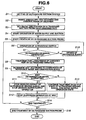
- first step S1 the surgeon sets the ultrasound suction system 1 in a treating state as shown in Fig. 1 .
- the surgeon connects the ultrasound suction probe 8 to the ultrasound driving signal generating unit 6 and the water supply and suction unit 12.
- next step S2 the surgeon inserts the insertion portion 45 of the endoscope 14 into the abdomen 4 of the patient 3 via the trocar 22 to enable the diseased part 5 or the like in the abdomen 4 to be observed by the observing section of the endoscope 14.
- next step S3 under observation by the endoscope 14, the surgeon inserts the ultrasound suction probe 8 into the abdomen 4 and sets the distal end portion side of the ultrasound suction probe 8 near the living tissue of the diseased part 5 to be opposed to the living tissue.
- next step S4 the surgeon sets the water supply and suction unit 12 in an operation state for water supply and suction, i.e., a state in which water is perfused.
- the ultrasound driving signal generating unit 6 changes to a state in which the ultrasound driving signal generating unit 6 generates an ultrasound driving signal only when the ultrasound switch 28a in the foot switch 28 is turned on.
- next step S5 under observation by the endoscope 14, the surgeon operates the ultrasound switch 28a and starts treatment by the ultrasound suction probe 8 for the living tissue of the diseased part 5.
- the surgeon performs operation for stepping on the ultrasound switch 28a and stops operation for stepping on the ultrasound switch 28a.
- the ultrasound switch 28a When the surgeon performs the operation for stepping on the ultrasound switch 28a, the ultrasound switch 28a generates an ultrasound ON signal.
- the surgeon stops the operation for stepping on the ultrasound switch 28a the ultrasound ON signal is stopped being generated (turned off).
- the ultrasound transducer 9 When the ultrasound ON signal is generated, as shown in step S8, the ultrasound transducer 9 ultrasonically vibrates. Under observation by the endoscope 14, the surgeon can perform treatment by the ultrasound vibration by bringing the distal end portion of the ultrasound suction probe 8 into contact with the living tissue of the diseased part 5.
- the mist determining and determination signal generating section 68 freezes a reference image in the reference image memory 70 at timing of the ultrasound ON signal and decides the reference image.
- the mist determining and determination signal generating section 68 acquires an observed image after the ultrasound ON signal, compares the observed image with the reference image, and starts determination of occurrence of mist exceeding the predetermined value.
- next step S10 the determining section of the mist determining and determination signal generating section 68 determines presence or absence of occurrence of mist exceeding the predetermined value and outputs a determination result.
- the controller 73 performs control for stopping (or reducing) output of the ultrasound driving signal for a short time and stopping (or reducing) water supply operation for a short time.
- step S12 When mist exceeding the predetermined value occurs as shown in step S12, the occurrence of the mist can be stopped or suppressed by stopping the output of the ultrasound driving signal. By setting a state in which mist does not occur or is suppressed, the surgeon can perform satisfactory observation using an observed image in which occurrence of mist is stopped or reduced.
- step S11 when the mist determination signal is not outputted, the control shown in step S11 is not performed. Specifically, when the mist determination signal is not outputted, as shown in step S13, the surgeon continues the treatment by the ultrasound suction probe 8 in an output state of the ultrasound driving signal and a water supply operation state while looking at the observed image.
- step S11 or S13 After processing in step S11 or S13, when instruction operation for ending treatment shown in step S14 is not performed, the processing returns to step S6. The processing in step S6 and subsequent steps explained above is repeated.
- step S15 the mist determining and determination signal generating section 68 performs processing for updating the reference image. After the processing, the processing returns to the processing in step S6.
- step S16 the treatment by the ultrasound suction probe 8 is ended.
- Figs. 7(A) to 7(F) show timing charts for explaining operation of main parts in Fig. 6 .
- step S4 of Fig. 6 as shown in Fig. 7(A) and Fig. 7(B) , operation of water supply and suction is started, for example, at time t1.
- the ultrasound switch 28a is turned on at time t2 after the time t1.
- an ultrasound ON signal is generated.
- the ultrasound driving signal generating unit 6 outputs an ultrasound driving signal to the ultrasound transducer 9.
- the ultrasound transducer 9 ultrasonically vibrates.
- step S8 of Fig. 6 the surgeon performs treatment using the ultrasound suction probe 8.
- the mist determining and determination signal generating section 68 starts a mist determination operation for determining presence or absence of occurrence of mist.
- the determination circuit 72 of the mist determining and determination signal generating section 68 outputs a determination result.
- Fig. 1 it is possible to fragment a fragile fat tissue or the like and expose an abundantly elastic blood vessel or the like by bringing the distal end portion 11 of the ultrasound suction probe 8 into contact with the surface of the living tissue of the diseased part 5 to give ultrasound vibration to the living tissue.
- the determination circuit 72 When mist exceeding the predetermined value occurs, as shown in Fig. 7(F) , the determination circuit 72 outputs a mist determination signal, for example, as shown at time t3. When the mist determination signal is outputted, the controller 73 immediately stops the water supply and stops the output of the ultrasound driving signal.
- the distal end portion 11 of the ultrasound suction probe 8 stops ultrasonically vibrating, for example, at time t4 after a short time from time t3, the occurrence of the mist is stopped or reduced to be sufficiently small. Then, since the mist determination signal stops being outputted, the stop of the water supply is released and the stop of the output of the ultrasound driving signal is released.
- the controller 73 may stop the suction in association with the stop of the water supply. In this case, the stop of the suction is released at time t4.
- the surgeon When the surgeon ends the treatment by the ultrasound suction probe 8, the surgeon turns off the ultrasound switch 28a, for example, at time t7. The surgeon stops the operation of the water supply as well at time t8.
- occurrence of mist exceeding the predetermined value is monitored and, when occurrence of mist exceeding the predetermined value is detected, the output of the ultrasound driving signal is automatically stopped (or reduced) and the water supply operation is also stopped (or reduced) such that the occurrence of the mist is reduced or stopped.
- the suction operation can also be associated with the water supply operation.
- the image signal Ira of the reference image added with the threshold Vth and the image signal Io of the observed image are compared to perform the determination.
- a maximum value Vm in the image signal Ir of the reference image and the image signal Io of the observed image shown in Fig. 5C may be compared to perform the determination.
- a maximum value Vmr of the image signal Ir of the reference image added with the threshold Vth may be set and the maximum value Vmr and the image signal Io of the observed image may be compared to perform the determination.
- Such setting can be performed according to, for example, instruction operation for selection setting by the setting section 74.
- mist determining and determination signal generating section 68 that determines presence or absence of occurrence of mist from an observed image is provided.
- an adhesion determining section (or an unclarity determining section) 81 is further provided that determines (detects), from an image signal of an observed image, a phenomenon in which the observed image becomes unclear because of adhesion of deposit due to mist on the outer surface of the objective lens 49.
- the adhesion determining section 81 determines that adhesion is present, the adhesion determining section 81 outputs an adhesion determination signal to the controller 73.
- the controller 73 performs control to perform gas supply and water supply operation by the gas supply and water supply unit 55 provided in the light source unit 18.
- Fig. 9A shows a schematic configuration of the adhesion determining section 81.
- an image signal of the memory 65 is stored in a reference memory 81 b via a frequency/luminance analysis circuit 81a having a function of an image acquiring section.
- the controller 73 outputs the control signal, for example, at time when the ultrasound switch 28a is turned on for the first time. It is likely that mist occurs after this time. However, at the starting time, the objective lens 49 of the observation window can be regarded as being in a clean state in which mist does not adhere to the objective lens 49.
- the frequency/luminance analysis circuit 81a captures an image signal serving as a reference image for one frame of the memory 65, divides an image region for one frame into small regions, performs an analysis of a frequency and luminance in the respective small regions, and stores data of the analysis in the reference memory 81 b as reference analysis data.
- the reference analysis data of the reference memory 81b is outputted to a comparison circuit 81 c.
- the frequency/luminance analysis circuit 81a captures an image signal of an observed image for each one frame, for example, after the ultrasound switch 28a is turned off, divides an image region for each one frame into small regions Rs as shown in Fig. 9B , performs an analysis of a frequency and luminance in the respective small regions Rs, and outputs data of the analysis to the comparison circuit 81c.
- the comparison circuit 81c performs comparison of frequency data and a luminance distribution between reference analysis data and analysis data in small regions corresponding thereto.
- mist or the like adheres to the outer surface of the objective lens 49, an original image-forming function by the objective lens 49 is deteriorated because of deposit. Therefore, in a distribution of a spatial frequency of an acquired observed image, compared with a state without deposit, high-frequency components decrease and low-frequency components increase.
- the comparison circuit 81 c outputs a comparison signal indicating that adhesion is likely to be present to the determination circuit 81d.
- the determination circuit 81d outputs an adhesion determination signal indicating determination that adhesion is present to the controller 73.
- the controller 73 performs control to perform gas supply and water supply operation by the gas supply and water supply unit 55. According to the control, gas and water are spouted to the outer surface of the objective lens 49 from the nozzle 50 functioning as the fluid spouting section, deposit such as scatters of mist adhering to the outer surface is removed, and the outer surface of the objective lens is set in a clean state.
- the controller 73 may further perform control for reducing or stopping supply of fluid by the water supply and suction unit 12 functioning as the fluid supplying section together with control for stopping or reducing output of the ultrasound driving signal by the ultrasound driving signal generating unit 6.
- the controller 73 may associate operation of suction with operation of water supply and perform control for reducing or stopping suction.
- the determination may be performed in an observed image for one frame.
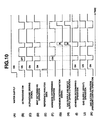
- FIG. 10(A) to 10(G) An operation example by the adhesion determining section 81 explained above is shown in Figs. 10(A) to 10(G) .
- an ultrasound driving signal shown in Fig. 10(C) is applied on the ultrasound transducer 9 of the ultrasound suction probe 8.
- mist determination operation by the mist determining and determination signal generating section 68 is performed.
- reference analysis data of a reference image is generated and stored in the reference memory 81b.
- the adhesion determining section 81 performs operation for adhesion determination.
- the adhesion determining section 81 acquires an observed image from the memory 65 and generates analysis data in a period in which the ultrasound switch 28a is turned off as shown in Fig. 10(B) . Further, the adhesion determining section 81 compares the reference analysis data and the analysis data and starts the operation for adhesion determination.
- the gas supply and water supply unit 55 spouts gas and water from the nozzle 50 and sets the outer surface of the objective lens 49 in a clean state.
- the operation for adhesion determination is not limited to such a case.
- the operation for adhesion determination may be performed in a period in which the ultrasound switch 28a is turned ON. In this case, the adhesion determination and the operation of the mist determining and determination signal generating section 68 are simultaneously performed.
- the operation for adhesion determination may be performed in a period in which the ultrasound switch 28a is turned off (not only in the period in which the ultrasound switch 28a is turned on).
- the first modification it is determined from an observed image whether mist adheres to the outer surface of the objective lens 49.
- gas and liquid as fluid are spouted by the gas supply and water supply unit 55 functioning as the fluid spouting section to remove deposit.
- This modification further includes means for preventing deposit due to mist from adhering to the outer surface of the objective lens 49.
- the gas supply and water supply unit 55 is caused to perform operation for supplying gas in synchronization with a period in which the ultrasound switch 28a is turned on.
- the gas By supplying the gas, the gas is spouted from the nozzle 50 to the outer surface of the objective lens 49 to prevent mist from adhering to the outer surface of the objective lens.
- the gas supply operation may be performed even in a period in which the ultrasound switch 28a is turned off. In this case, it is advisable to associate the gas suction operation.
- heating means is further provided on the distal end side of the endoscope 14 and combined with the functions by the fluid spouting section and the like explained above.
- a fat tissue included in mist is liquefied or changes to an easily removable state (compared with the case of unheated temperature).
- a heating device 85a that heats the vicinity of the distal end portion 47 is provided near the distal end portion 47 of the insertion portion 45 of the endoscope 14.
- the heating device 85a is formed in a cylindrical portion forming an outer circumferential face of the distal end portion 47 and is connected to a power supply circuit 85c for heating, which is provided in the light source unit 18, via a signal cable 85b inserted through the insertion portion 45. Operation of the power supply circuit 85c is controlled by the controller 56 or the controllers 56 and 73.
- a temperature sensor 85d is provided in the heating device 85a.
- the temperature sensor 85d is connected to the controller 56 in the light source unit 18 via a signal cable 85e.
- the controller 56 performs, according to a temperature detection signal of the temperature sensor 85d, control to keep temperature for heating by the heating device 85a from the power supply circuit 85c at appropriate temperature.
- the controller 56 may directly control, according to a temperature detection signal of the temperature sensor 85d, power supply by the power supply circuit 85c to maintain the predetermined temperature.
- a heater 55a that heats, for example, gas to be supplied in the gas supply and water supply unit 55 may be provided.
- the gas heated by the heater 55a may be supplied via the gas supply and water supply tube 57 and spouted from the nozzle 50 that projects from a distal end face of the distal end portion 47.
- Figs. 12(A) to 12(D) show schematic operation explanatory diagrams in this modification.
- the controller 73 or 26 performs control to also perform operation of gas suction to keep the inside of the abdomen 4 at fixed pressure.
- Heated water may be supplied simultaneously with the operation for supplying the gas heated by the heater 55a.
- a heating device may be provided on the inside of the endoscope. When such a configuration is adopted, there is an advantage that a special additional product is unnecessary when the endoscope is used. As a place to be heated, it is advisable that, for example, at least the outer surface of the objective lens 49 can be heated.
- the heated gas or the like is supplied using the nozzle 50 projecting in one place from the distal end face of the distal end portion 47.
- the supply of the gas is not limited to the case of the configuration in which the nozzle 50 is used.
- Fig. 13A shows an example in which a gas supply port (or a spout port) 86a different from the nozzle 50 is provided.
- a gas supply port (or a spout port) 86a different from the nozzle 50 is provided.
- a semicylindrical gas supply pipe 86b is provided along an outer circumferential face of the insertion portion 45.
- the gas supply pipe 86b functions as the gas supply port 86a opened in a semicylindrical shape on the distal end face of the distal end portion 47.
- the gas supply port 86a is opened to be opposed to the distal end face. Supplied gas is spouted along the distal end face as indicated by arrows. The objective lens 49 and the illumination lens 48 are exposed on the distal end face.
- heated gas is spouted to make it easy to remove, to a circumferential edge side on an opposite side of the gas supply port 86a, deposit due to mist containing a fat tissue adhering to, for example, outer surfaces of the objective lens 49 and the illumination lens 48.
- the nozzle 50 is provided at the distal end portion of the gas supply and water supply tube 58 provided on an inside of the insertion portion 45 of the endoscope 14.
- a gas supply port (or nozzle) 86d may be provided at a distal end portion of the gas supply pipe 86c provided along the outer circumferential face of the insertion portion 45.
- Heated gas may be spouted or delivered from the gas supply port 86d.
- water repellent films 87a and 87b having a water repelling function may be provided on the outer surfaces of the objective lens 49 and the illumination lens 48.
- the water repellent films 87a and 87b it is possible to prevent mist from easily adhering to the outer surfaces and, even when mist adheres to the outer surfaces, it is possible to easily remove the mist.
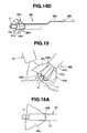
- Fig. 14A shows a configuration of an ultrasound suction probe 8B according to a second embodiment of the present invention.
- This embodiment includes means for preventing, even when mist scatters, the scatter from affecting a satisfactory observation field of view of the endoscope 14.
- Other components are the same as, for example, those in the first embodiment.
- the outer pipe 31 of the ultrasound suction probe 8B shown in Fig. 2 is replaced with an inner sheath 91 a and an outer sheath 91 b is provided on an outer side of the inner sheath 91 a.
- a distal end of the outer sheath 91b is located further on a rear side than a distal end of the inner sheath 91a.
- the distal end portion 11 of the ultrasound suction probe 8B arranged on an inner side of the inner sheath 91a is arranged to slightly project from a distal end portion of the inner sheath 91 a.
- an openable and closable umbrella 92a is arranged to be movable in an axis direction.
- An operation lever 92b movable to the front is provided in the gripping portion 46 to which a rear end of the outer sheath 91b is fixed. A surgeon can project the umbrella 92a retracted in a distal end portion of the outer sheath 91b to project as shown in Fig. 14B by performing operation for moving (pressing) the operation lever 92b to a front side.
- the umbrella 92a is coupled to the operation lever 92b via a slide bar 92c as it is seen from a structure in which the outer sheath 91b is detached. Therefore, the surgeon can project the umbrella 92a as shown in Figs. 14B and 14D by performing operation for moving the operation lever 92b to the front side as explained above.
- the umbrella 92a includes a transparent sheet 92e formed in a substantially conical shape such that a distal end side expands compared with a proximal end side and plural wire-like framework sections 92d provided along an axis direction of the sheaths 91a and 91b to reinforce the transparent sheet 92e.
- a proximal end of the framework sections 92d is a fixed ring section.
- the framework sections 92d are formed of shape memory metal or the like to have a characteristic that a distal end side of the framework sections 92d expands. Soil such as mist adhering to the umbrella 92a is periodically cleaned by perfusing water to a gap between the inner sheath 91a and the outer sheath 91 b.
- Fig. 15 shows a state in which treatment by ultrasound vibration is applied to a living tissue of the diseased part 5 using the ultrasound suction probe 8B having such a configuration.
- the surgeon operates the operation lever 92b and sets the umbrella 92a in an open state. Since the umbrella 92a is formed by the transparent sheet 92e, the surgeon can observe a peripheral portion of the diseased part 5 seeing through the transparent sheet 92e.
- the mist can be prevented from scattering to an observation field of view side of the endoscope 14 using the umbrella 92a. Therefore, the surgeon can smoothly perform treatment by the ultrasound suction probe 8B under observation by the endoscope 14.
- Figs. 16A and 16B show a configuration on a distal end side of an ultrasound suction probe 8C according to a third embodiment of the present invention.
- the ultrasound suction probe 8C is formed by detachably attaching a bag 95a, which is formed of, for example, a transparent member, on the distal end side of the ultrasound suction probe 8.
- the bag 95a is formed in a substantially semispherical shape or a conical shape.
- a proximal end of the bag 95a is detachably attached to the outer pipe 31 of the ultrasound suction probe 8 by a ring 95b having elasticity such as rubber.
- a distal end side of the bag 95a is opened in a substantially circular shape.
- Fig. 17 shows a state in which processing utilizing ultrasound vibration is performed using the ultrasound suction probe 8C in this embodiment.
- a peripheral portion of the treatment target diseased part 5 is set to be on an inner side of the bag 95a under observation by the endoscope 14. Under observation by the endoscope 14, the surgeon fixes, via a not-shown treatment instrument, plural places at an opened circumferential edge of the bag 95a to the surface of the living tissue opposed to the places with clips 96.
- the surgeon performs treatment with the ultrasound suction probe 8C.
- the ultrasound suction probe 8C Even if mist scatters, it is possible to effectively prevent the mist from scattering from an inside of the bag 95a to an outside. It is possible to observe the peripheral portion of the diseased part 5 seeing through the transparent bag 95a using the endoscope 14.
- an output mode setting section 74b may be provided in the setting section 74 and an ultrasound driving signal may be intermittently outputted according to selection setting by the output mode setting section 74b.
- Fig. 18 shows a configuration of the processor 17 and the ultrasound driving signal generating unit 6 in an ultrasound suction system according to a fourth embodiment of the present invention.
- a clock generation circuit 101, a gate circuit 102, an image acquisition circuit 103, an image processing circuit 104, and a monitor 105 are further provided in the first embodiment.
- the ultrasound switch 28a when the ultrasound switch 28a is turned on, opening and closing of the gate circuit 102 in the ultrasound driving signal generating unit 6 is controlled according to a clock of the clock generation circuit 101 provided in the processor 17.
- An output signal of the oscillator 36 is intermittently outputted to the output circuit 37 according to the opening and closing of the gate circuit 102.
- the clock circuit 69a shown in Fig. 4 may be used as the clock generation circuit 101.
- An image signal of the memory 65 is outputted to the second monitor 105 via the second image acquisition circuit 103 that acquires an image in synchronization with a clock and the image processing circuit 104 that performs image processing.
- the second image acquisition circuit 103 acquires the image signal from the memory 65 in a period in which an ultrasound driving signal is turned off (see Fig. 19(E) ) and freezes and stores the image signal in a memory 103a in a period in which the ultrasound driving signal is turned on (see Fig. 19(F) ).
- the image signal stored in the memory 103a is updated.
- An output signal of the second image acquisition circuit 103 is converted into a standard image signal by the image processing circuit 104 and outputted to the monitor 105.
- An observed image acquired by the second image acquisition circuit 103 is displayed on the monitor 105.
- the image acquisition circuit 103 acquires a moving image from the memory 65 at a normal frame rate. The moving image is displayed on the monitor 105.
- the second image acquisition circuit 103 and the image processing circuit 104 are controlled by the controller 73.
- the output mode setting section 74b is provided in the setting section 74. It is possible to select, according to selection setting by the output mode setting section 74b, one output mode from the continuous output mode and an intermittent output mode explained below as in the first embodiment.
- the gate circuit 102 When the continuous output mode is selected, the gate circuit 102 is usually open. Operation same as that in the first embodiment is performed.
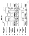
- Figs. 19(A) to 19(F) show timing charts for operation explanation in the case in which the intermittent output mode in this embodiment is selected.
- the ultrasound switch 28a is turned on and off to perform treatment utilizing ultrasound vibration by the ultrasound suction probe 8.
- an ultrasound driving signal is intermittently outputted as shown in Fig. 19(C) in synchronization with a clock.
- the mist determining and determination signal generating section 68 starts mist determination operation in a period in which the ultrasound switch 28a is turned on as explained in the first embodiment.
- the second image acquisition circuit 103 acquires, in synchronization with the ultrasound driving signal outputted intermittently, an observed image in a period in which the ultrasound driving signal is off.
- a standard image signal generated according to the observed image is displayed on the monitor 105.
- an observed image of a moving image i.e., a normal moving image is acquired at a predetermined frame rate (e.g., 20 frames/sec or 30 frames/sec).
- Fig. 19(E) when intermittently-acquired observed images are represented as A, B, C, ..., F, and G, as shown in Fig. 19(F) , for example, the acquired observed images are stored in the memory 103a at a double period.
- the observed images are displayed as a moving image at a double period (in this example, a period of ON/OFF of the ultrasound driving signal) on the monitor 105.
- the period of ON/OFF of the ultrasound driving signal may be able to be variably set by the setting section 74. Consequently, the surgeon may be able to select, according to treatment, a period in which the ultrasound driving signal is turned on and a period in which the ultrasound driving signal is turned off in the intermittent output mode. Duties in the period in which the ultrasound driving signal is turned on and the period in which the ultrasound driving signal is turned off may be able to be variably set by the setting section 74.
- Fig. 19(E) When each of the intermittently-acquired observed images A and the like in Fig. 19(E) is plural frames, an average of the frames is set in an observed image of one frame. As shown in Fig. 19(I) explained later, only an observed image of one frame or one field may be acquired. In the case of a normal image in Fig. 19(F) , observed images are recorded in the memory 103a at the predetermined frame rate. In Fig. 19(F) , operation of the recording is indicated by diagonal lines.
- the ultrasound driving signal is intermittently outputted and observed images acquired in periods in which the ultrasound driving signal is not outputted are displayed, on the monitor 105 functioning as display means, as a moving image at a low frame rate equal to or lower than 1/2 of the normal frame rate for a moving image.
- the controller 73 reduces an ultrasound output value outputted from the output circuit 37.
- the controller 73 reduces the operation of water supply and suction of the water supply and suction unit 12 shown in Fig. 19(A) .
- Fig. 19(H) an example in which an ultrasound output value is reduced when a mist determination signal is outputted is explained.
- the ultrasound output value may be set to 0, i.e., the output of the ultrasound driving signal may be stopped.
- an image of one frame or one field immediately before the ultrasound driving signal in the period in which the ultrasound driving signal is off is turned on may be acquired.
- This embodiment has effects same as those of the first embodiment. Besides, it is possible to display, on the second monitor 105, observed images with little adverse effect due to occurrence of mist exceeding the predetermined value. Therefore, the surgeon can smoothly perform treatment by ultrasound vibration.
- operation for, until a mist determination signal is generated, outputting the ultrasound driving signal in the continuous output mode as explained in the first embodiment and, after the mist determination signal is generated, changing the continuous output mode to the intermittent output mode may be selected or controlled.
- the configuration including, in the ultrasound suction probe 8, the ultrasound transducer 9 functioning as the ultrasound generating section that generates ultrasound vibration is explained.
- a configuration in which the ultrasound generating section is provided on the outside of the ultrasound suction probe 8 may be adopted.
- the controller 73 is shown as, for example, a component separate from the mist determining and determination signal generating section 68.
- a configuration in which the controller 73 includes the mist determining and determination signal generating section 68 may be adopted.
- a configuration in which the controller 73 includes the adhesion determining section 81 may be adopted.
Landscapes
- Health & Medical Sciences (AREA)
- Surgery (AREA)
- Life Sciences & Earth Sciences (AREA)
- Engineering & Computer Science (AREA)
- Molecular Biology (AREA)
- Animal Behavior & Ethology (AREA)
- Veterinary Medicine (AREA)
- Biomedical Technology (AREA)
- Heart & Thoracic Surgery (AREA)
- Medical Informatics (AREA)
- Public Health (AREA)
- Nuclear Medicine, Radiotherapy & Molecular Imaging (AREA)
- General Health & Medical Sciences (AREA)
- Dentistry (AREA)
- Mechanical Engineering (AREA)
- Oral & Maxillofacial Surgery (AREA)
- Pathology (AREA)
- Surgical Instruments (AREA)
- Ultra Sonic Daignosis Equipment (AREA)
- Endoscopes (AREA)
Claims (19)
- Ultraschall-Saugsystem (1) mit:einer Ultraschall-Antriebssignal-Erzeugungseinheit (6), die ein Ultraschall-Antriebssignal zu erzeugen vermag;einer Ultraschall-Saugeinheit (8) mit einer Ultraschall-Erzeugungseinheit (9), die dazu eingerichtet ist, Ultraschall-Schwingungsenergie entsprechend dem Anlegen des Ultraschall-Antriebssignals zu erzeugen, und einer Saugeinheit (10a), die dazu eingerichtet ist, die durch die Ultraschall-Erzeugungseinheit (9) erzeugte Ultraschall-Schwingungsenergie von einem distalen Endbereich (11) einer Schwingungsübertragungseinheit (10), die dazu eingerichtet ist, die Ultraschall-Schwingungsenergie zu einem lebenden Gewebe des Behandlungsziels zu übertragen, an das lebende Gewebe des Behandlungsziels zu übergeben, um dadurch das lebende Gewebe zu zerteilen und abgetrennte Stücke des lebenden Gewebes abzusaugen;einer Beobachtungseinheit (15), die eine Beobachtungsfunktion zum Beobachten des lebenden Gewebes aufweist, welches der Seite des distalen Endbereichs (11) der Schwingungsübertragungseinheit (10) gegenüberliegt; undeiner Fluidzuführeinheit (41), die einer Oberfläche des lebenden Gewebes Fluid zuführt;dadurch gekennzeichnet, dass das Ultraschall-Saugsystem (1) des Weiteren aufweist:eine Bilderfassungseinheit (69), die über die Beobachtungseinheit (15) ein beobachtetes Bild zu erfassen vermag, in dem Dunst von der Oberfläche des lebenden Gewebes in einem Zustand erzeugt wird, in welchem die Ultraschall-Schwingungsenergie abgegeben wird; undeinen Steuerbereich (73), der dazu eingerichtet ist, die Ausgabe des Ultraschall-Antriebssignals durch die Ultraschall-Antriebssignal-Erzeugungseinheit (6) und/oder die Zufuhr des Fluids auf der Grundlage eines Vergleichsergebnisses zu steuern, das erzielt wird durch Vergleichen von: einem Referenzbild, das einem Zustand entspricht, in dem der Dunst von der Zeit des Abgebens der Ultraschall-Schwingungsenergie an den distalen Endbereich (11) der Schwingungsübertragungseinheit (10) bis zur Zeit unmittelbar nach dem Abgeben der Ultraschall-Schwingungsenergie im Wesentlichen nicht durch das Ultraschall-Antriebssignal erzeugt wird, und dem durch die Bilderfassungseinheit (69) erfassten beobachteten Bild.
- Ultraschall-Saugsystem (1) nach Anspruch 1, das des Weiteren eine Bestimmungseinheit (72) aufweist, die auf der Grundlage des Vergleichsergebnisses bestimmt, ob das beobachtete Bild ein beobachtetes Bild in einem Zustand ist, in welchem Dunst erzeugt wird, der sich zum Referenzbild um einen vorgegebenen oder höheren Wert geändert hat, wobei, in einem Fall eines Bestimmungsergebnisses, bei dem der Dunst sich um den vorgegebenen oder höheren Wert geändert hat, der Steuerbereich (73) die Steuerung zum Reduzieren oder Anhalten der Zufuhr des Fluids durch die Fluidzuführeinheit (41) zusammen mit der Steuerung zum Anhalten oder Reduzieren der Ausgabe des Ultraschall-Antriebssignals durch die Ultraschall-Antriebssignal-Erzeugungseinheit (6) durchführt.
- Ultraschall-Saugsystem (1) nach Anspruch 2, das des Weiteren eine Saugeinrichtung (42) aufweist, zum Absaugen der abgetrennten lebenden Gewebestücke zusammen mit dem Fluid, das der Oberfläche des lebenden Gewebes zugeführt wird, über einen Saugschlauch (13b), der mit der Saugeinheit (10a) in Verbindung steht, wobei
wenn ein Bestimmungsergebnis erzielt wird, bei dem beobachtete Bild sich zum Referenzbild auf der Grundlage des Ergebnisses eines Vergleichs zwischen dem Referenzbild und dem beobachteten Bild um einen vorgegebenen oder höheren Wert geändert hat, der Steuerbereich (73) die Steuerung zum Reduzieren oder Anhalten des Saugprozesses durch die Saugeinrichtung (42) durchführt. - Ultraschall-Saugsystem (1) nach Anspruch 1, wobei die Beobachtungseinheit (15) ein Endoskop (14) aufweist, das an einem distalen Endbereich eines Einführbereichs (45) vorgesehen ist.
- Ultraschall-Saugsystem (1) nach Anspruch 2, wobei die Bilderfassungseinheit (69) als Referenzbild ein beobachtetes Bild festlegt, das von der Beobachtungseinheit (15) in einem Zustand erfasst wird, in welchem das Ultraschall-Antriebssignal im Wesentlichen nicht erzeugt wird, und die Bestimmungseinheit (72) feststellt, ob Dunst erzeugt wird oder nicht, indem im Hinblick auf das Referenzbild die Bestimmung durchgeführt wird, ob das beobachtete Bild, das von der Beobachtungseinheit (15) in einem Zustand erfasst wird, in dem das Ultraschall-Antriebssignal erzeugt wird, ein pulsartiges Bildsignal als Bildsignal entsprechend der Erzeugung von Dunst aufweist.
- Ultraschall-Saugsystem (1) nach Anspruch 5, wobei die Bestimmungseinheit (72) feststellt, ob Dunst erzeugt wird oder nicht, indem sie bestimmt, ob das beobachtete Bild ein Bild mit einem Luminanzwert gleich oder größer als ein Schwellenwert ist, der im Vergleich zum Referenzbild vorab eingestellt wird.
- Ultraschall-Saugsystem (1) nach Anspruch 6, wobei die Bestimmungseinheit (72) feststellt, ob das beobachtete Bild eine vorgegebene oder höhere Anzahl von Luminanzwerten einzeln aufweist, die gleich oder größer als der Schwellenwert in einer vorgegebenen Region im Vergleich zum Referenzbild sind, und ein Dunstbestimmungssignal erzeugt, wenn das beobachtete Bild die vorgegebene oder höhere Anzahl von Luminanzwerten aufweist.
- Ultraschall-Saugsystem (1) nach Anspruch 5, das des Weiteren eine Anhaftung-Bestimmungseinheit (81) aufweist, die aus dem beobachteten Bild feststellt, ob eine Ablagerung, die mit dem Zerstäuben des Dunstes zu tun hat, an einer Außenfläche eines distalen Endbereichs der Beobachtungseinheit (15) anhaftet, wobei die Anhaftung-Bestimmungseinheit (81) ein Bestimmungssignal erzeugt, wenn die Anhaftung-Bestimmungseinheit feststellt, dass die Ablagerung an der Außenfläche anhaftet.
- Ultraschall-Saugsystem (1) nach Anspruch 8, wobei der Steuerbereich (73) auf der Grundlage der Erzeugung des Bestimmungssignals eine Steuerung durchführt, zum Herausspritzen des Fluids aus einer Fluidspritzeinheit (50), die am distalen Endbereich (47) eines Endoskops (14), an dem sich die Beobachtungseinheit (15) befindet, vorgesehen ist, auf eine Außenfläche des distalen Endbereichs der Beobachtungseinheit (15).
- Ultraschall-Saugsystem (1) nach Anspruch 9, wobei die Anhaftung-Bestimmungseinheit (81) das Bestimmungssignal im Falle eines Bestimmungsergebnisses erzeugt, bei dem eine Differenz zwischen einem Maximum und einem Minimum von Luminanzwerten in dem beobachteten Bild gleich oder kleiner als ein vorgegebener Wert ist.
- Ultraschall-Saugsystem (1) nach Anspruch 9, wobei die Anhaftung-Bestimmungseinheit (81) eine Analyseeinheit (81a) aufweist, die eine Raumfrequenzverteilung im beobachteten Bild analysiert, und die Anhaftung-Bestimmungseinheit das Bestimmungssignal im Falle eines Bestimmungsergebnisses erzeugt, bei dem eine Hochfrequenzkomponente der Raumfrequenz gleich oder kleiner als ein vorgegebener Wert ist.
- Ultraschall-Saugsystem (1) nach Anspruch 5, wobei der Steuerbereich (73) des Weiteren eine Steuerung durchführt, zum Heraussprühen von Gas aus einer Gassprüheinheit (50), die am distalen Endbereich (47) eines Endoskops (14), an dem sich die Beobachtungseinheit (15) befindet, vorgesehen ist, auf eine Außenfläche eines distalen Endbereichs der Beobachtungseinheit (15) zumindest in einer Zeitspanne, in der das Ultraschall-Antriebssignal erzeugt wird.
- Ultraschall-Saugsystem (1) nach Anspruch 12, das des Weiteren aufweist:eine Pneumoperitoneum-Einheit (24), die Gas zu einem Körperhohlraum zuführt und aus ihm absaugt, in den mindestens eine distale Endseite des Endoskops (14) eingeführt ist, wobeider Steuerbereich (73) die Funktion zumindest der Gasabsaugung in der Pneumoperitoneum-Einheit (24) auf der Grundlage von Druckinformation über das Gas im Körperhohlraum steuert.
- Ultraschall-Saugsystem (1) nach Anspruch 2, das des Weiteren aufweist:eine Heizeinrichtung (85a), die an einem distalen Endbereich (47) eines Endoskops (14), an dem sich die Beobachtungseinheit (15) befindet, vorgesehen ist und eine Umgebung des distalen Endbereichs (47) heizt; undeine Stromversorgungseinheit (85c), welche die Heizeinrichtung (85a) mit elektrischem Strom zum Heizen versorgt.
- Ultraschall-Saugsystem (1) nach Anspruch 10, wobei in einem Fall, in dem das Bestimmungssignal erzeugt wird, der Steuerbereich (73) die Steuerung zum Reduzieren oder Anhalten der Zufuhr des Fluids durch die Fluidzuführeinheit (41) zusammen mit der Steuerung zum Anhalten oder Reduzieren der Ausgabe des Ultraschall-Antriebssignals durch die Ultraschall-Antriebssignal-Erzeugungseinheit (6) durchführt.
- Ultraschall-Saugsystem (1) nach Anspruch 2, das des Weiteren aufweist:einen transparenten Schirm (92a), der so vorgesehen ist, dass er auf einer Innenseite einer Ummantelung an einer distalen Endseite der Ultraschall-Saugeinheit (8) vorstehen und sich zurückziehen kann, wobei der Schirm (92a), wenn er vorsteht, eine Umgebung eines distalen Endbereichs einer Ultraschall-Saugeinheit (8) mit einer transparenten Folie (92e) bedeckt, die eine im Wesentlichen konische Form aufweist.
- Ultraschall-Saugsystem (1) nach Anspruch 2, das des Weiteren aufweist:einen transparenten Beutel (95a), dessen proximales Ende abnehmbar vorgesehen ist und dessen distale Endseite geöffnet ist, an einer distalen Endseite der Ultraschall-Saugeinheit (8), wobei ein geöffneter Umfangsrand des Beutels (95a) durch eine Klemme (96) an einem lebenden Gewebe um einen distalen Endbereich der Ultraschall-Saugeinheit (8) herum befestigt werden kann.
- Ultraschall-Saugsystem (1) nach Anspruch 2, wobei die Ultraschall-Antriebssignal-Erzeugungseinheit (6) einen kontinuierlichen Ausgabemodus zum kontinuierlichen Ausgeben des erzeugten Ultraschall-Antriebssignals und einen intermittierenden Ausgabemodus zum intermittierenden Ausgeben des Ultraschall-Antriebssignals zu einer vorgegebenen Zeitdauer aufweist, die eine AN-Zeit und eine AUS-Zeit enthält.
- Ultraschall-Saugsystem (1) nach Anspruch 2, wobei der Steuerbereich (73) die Steuerung einschließlich der Reduzierung der Ausgabe des Ultraschall-Antriebssignals durch Steuern eines Stromwertes des Ultraschall-Antriebssignals durchführt, das durch die Ultraschall-Antriebssignal-Erzeugungseinheit ausgegeben wird.
Applications Claiming Priority (2)
| Application Number | Priority Date | Filing Date | Title |
|---|---|---|---|
| US35564610P | 2010-06-17 | 2010-06-17 | |
| PCT/JP2011/063511 WO2011158792A1 (ja) | 2010-06-17 | 2011-06-13 | 超音波吸引システム及び超音波吸引方法 |
Publications (3)
| Publication Number | Publication Date |
|---|---|
| EP2508143A1 EP2508143A1 (de) | 2012-10-10 |
| EP2508143A4 EP2508143A4 (de) | 2013-01-09 |
| EP2508143B1 true EP2508143B1 (de) | 2014-02-26 |
Family
ID=45348191
Family Applications (1)
| Application Number | Title | Priority Date | Filing Date |
|---|---|---|---|
| EP11795697.9A Active EP2508143B1 (de) | 2010-06-17 | 2011-06-13 | Ultraschallsaugvorrichtung |
Country Status (5)
| Country | Link |
|---|---|
| US (1) | US20120116222A1 (de) |
| EP (1) | EP2508143B1 (de) |
| JP (1) | JP5006475B2 (de) |
| CN (1) | CN102762160B (de) |
| WO (1) | WO2011158792A1 (de) |
Cited By (85)
| Publication number | Priority date | Publication date | Assignee | Title |
|---|---|---|---|---|
| US9192431B2 (en) | 2010-07-23 | 2015-11-24 | Ethicon Endo-Surgery, Inc. | Electrosurgical cutting and sealing instrument |
| US9265926B2 (en) | 2013-11-08 | 2016-02-23 | Ethicon Endo-Surgery, Llc | Electrosurgical devices |
| US9283027B2 (en) | 2011-10-24 | 2016-03-15 | Ethicon Endo-Surgery, Llc | Battery drain kill feature in a battery powered device |
| US9295514B2 (en) | 2013-08-30 | 2016-03-29 | Ethicon Endo-Surgery, Llc | Surgical devices with close quarter articulation features |
| US9408660B2 (en) | 2014-01-17 | 2016-08-09 | Ethicon Endo-Surgery, Llc | Device trigger dampening mechanism |
| US9456864B2 (en) | 2010-05-17 | 2016-10-04 | Ethicon Endo-Surgery, Llc | Surgical instruments and end effectors therefor |
| US9492224B2 (en) | 2012-09-28 | 2016-11-15 | EthiconEndo-Surgery, LLC | Multi-function bi-polar forceps |
| US9526565B2 (en) | 2013-11-08 | 2016-12-27 | Ethicon Endo-Surgery, Llc | Electrosurgical devices |
| US9554846B2 (en) | 2010-10-01 | 2017-01-31 | Ethicon Endo-Surgery, Llc | Surgical instrument with jaw member |
| US9554854B2 (en) | 2014-03-18 | 2017-01-31 | Ethicon Endo-Surgery, Llc | Detecting short circuits in electrosurgical medical devices |
| US9610091B2 (en) | 2010-04-12 | 2017-04-04 | Ethicon Endo-Surgery, Llc | Electrosurgical cutting and sealing instruments with jaws having a parallel closure motion |
| US9700333B2 (en) | 2014-06-30 | 2017-07-11 | Ethicon Llc | Surgical instrument with variable tissue compression |
| US9737355B2 (en) | 2014-03-31 | 2017-08-22 | Ethicon Llc | Controlling impedance rise in electrosurgical medical devices |
| US9737358B2 (en) | 2010-06-10 | 2017-08-22 | Ethicon Llc | Heat management configurations for controlling heat dissipation from electrosurgical instruments |
| US9757186B2 (en) | 2014-04-17 | 2017-09-12 | Ethicon Llc | Device status feedback for bipolar tissue spacer |
| US9795436B2 (en) | 2014-01-07 | 2017-10-24 | Ethicon Llc | Harvesting energy from a surgical generator |
| US9808308B2 (en) | 2010-04-12 | 2017-11-07 | Ethicon Llc | Electrosurgical cutting and sealing instruments with cam-actuated jaws |
| US9814514B2 (en) | 2013-09-13 | 2017-11-14 | Ethicon Llc | Electrosurgical (RF) medical instruments for cutting and coagulating tissue |
| US9848937B2 (en) | 2014-12-22 | 2017-12-26 | Ethicon Llc | End effector with detectable configurations |
| US9861428B2 (en) | 2013-09-16 | 2018-01-09 | Ethicon Llc | Integrated systems for electrosurgical steam or smoke control |
| US9872725B2 (en) | 2015-04-29 | 2018-01-23 | Ethicon Llc | RF tissue sealer with mode selection |
| US9877776B2 (en) | 2014-08-25 | 2018-01-30 | Ethicon Llc | Simultaneous I-beam and spring driven cam jaw closure mechanism |
| US9913680B2 (en) | 2014-04-15 | 2018-03-13 | Ethicon Llc | Software algorithms for electrosurgical instruments |
| US10092310B2 (en) | 2014-03-27 | 2018-10-09 | Ethicon Llc | Electrosurgical devices |
| US10092348B2 (en) | 2014-12-22 | 2018-10-09 | Ethicon Llc | RF tissue sealer, shear grip, trigger lock mechanism and energy activation |
| US10111699B2 (en) | 2014-12-22 | 2018-10-30 | Ethicon Llc | RF tissue sealer, shear grip, trigger lock mechanism and energy activation |
| US10117702B2 (en) | 2015-04-10 | 2018-11-06 | Ethicon Llc | Surgical generator systems and related methods |
| US10117667B2 (en) | 2010-02-11 | 2018-11-06 | Ethicon Llc | Control systems for ultrasonically powered surgical instruments |
| US10130410B2 (en) | 2015-04-17 | 2018-11-20 | Ethicon Llc | Electrosurgical instrument including a cutting member decouplable from a cutting member trigger |
| US10154852B2 (en) | 2015-07-01 | 2018-12-18 | Ethicon Llc | Ultrasonic surgical blade with improved cutting and coagulation features |
| US10159524B2 (en) | 2014-12-22 | 2018-12-25 | Ethicon Llc | High power battery powered RF amplifier topology |
| US10166060B2 (en) | 2011-08-30 | 2019-01-01 | Ethicon Llc | Surgical instruments comprising a trigger assembly |
| US10172669B2 (en) | 2009-10-09 | 2019-01-08 | Ethicon Llc | Surgical instrument comprising an energy trigger lockout |
| US10179022B2 (en) | 2015-12-30 | 2019-01-15 | Ethicon Llc | Jaw position impedance limiter for electrosurgical instrument |
| US10194972B2 (en) | 2014-08-26 | 2019-02-05 | Ethicon Llc | Managing tissue treatment |
| US10194973B2 (en) | 2015-09-30 | 2019-02-05 | Ethicon Llc | Generator for digitally generating electrical signal waveforms for electrosurgical and ultrasonic surgical instruments |
| US10194976B2 (en) | 2014-08-25 | 2019-02-05 | Ethicon Llc | Lockout disabling mechanism |
| US10201382B2 (en) | 2009-10-09 | 2019-02-12 | Ethicon Llc | Surgical generator for ultrasonic and electrosurgical devices |
| US10226273B2 (en) | 2013-03-14 | 2019-03-12 | Ethicon Llc | Mechanical fasteners for use with surgical energy devices |
| US10245064B2 (en) | 2016-07-12 | 2019-04-02 | Ethicon Llc | Ultrasonic surgical instrument with piezoelectric central lumen transducer |
| US10245065B2 (en) | 2007-11-30 | 2019-04-02 | Ethicon Llc | Ultrasonic surgical blades |
| US10251664B2 (en) | 2016-01-15 | 2019-04-09 | Ethicon Llc | Modular battery powered handheld surgical instrument with multi-function motor via shifting gear assembly |
| US10278721B2 (en) | 2010-07-22 | 2019-05-07 | Ethicon Llc | Electrosurgical instrument with separate closure and cutting members |
| USD847990S1 (en) | 2016-08-16 | 2019-05-07 | Ethicon Llc | Surgical instrument |
| US10285724B2 (en) | 2014-07-31 | 2019-05-14 | Ethicon Llc | Actuation mechanisms and load adjustment assemblies for surgical instruments |
| US10285723B2 (en) | 2016-08-09 | 2019-05-14 | Ethicon Llc | Ultrasonic surgical blade with improved heel portion |
| US10299810B2 (en) | 2010-02-11 | 2019-05-28 | Ethicon Llc | Rotatable cutting implements with friction reducing material for ultrasonic surgical instruments |
| US10314638B2 (en) | 2015-04-07 | 2019-06-11 | Ethicon Llc | Articulating radio frequency (RF) tissue seal with articulating state sensing |
| US10321950B2 (en) | 2015-03-17 | 2019-06-18 | Ethicon Llc | Managing tissue treatment |
| US10335182B2 (en) | 2012-06-29 | 2019-07-02 | Ethicon Llc | Surgical instruments with articulating shafts |
| US10335614B2 (en) | 2008-08-06 | 2019-07-02 | Ethicon Llc | Devices and techniques for cutting and coagulating tissue |
| US10335183B2 (en) | 2012-06-29 | 2019-07-02 | Ethicon Llc | Feedback devices for surgical control systems |
| US10342602B2 (en) | 2015-03-17 | 2019-07-09 | Ethicon Llc | Managing tissue treatment |
| US10357303B2 (en) | 2015-06-30 | 2019-07-23 | Ethicon Llc | Translatable outer tube for sealing using shielded lap chole dissector |
| US10376305B2 (en) | 2016-08-05 | 2019-08-13 | Ethicon Llc | Methods and systems for advanced harmonic energy |
| US10398466B2 (en) | 2007-07-27 | 2019-09-03 | Ethicon Llc | Ultrasonic end effectors with increased active length |
| US10420580B2 (en) | 2016-08-25 | 2019-09-24 | Ethicon Llc | Ultrasonic transducer for surgical instrument |
| US10420579B2 (en) | 2007-07-31 | 2019-09-24 | Ethicon Llc | Surgical instruments |
| US10426507B2 (en) | 2007-07-31 | 2019-10-01 | Ethicon Llc | Ultrasonic surgical instruments |
| US10433900B2 (en) | 2011-07-22 | 2019-10-08 | Ethicon Llc | Surgical instruments for tensioning tissue |
| US10441310B2 (en) | 2012-06-29 | 2019-10-15 | Ethicon Llc | Surgical instruments with curved section |
| US10441345B2 (en) | 2009-10-09 | 2019-10-15 | Ethicon Llc | Surgical generator for ultrasonic and electrosurgical devices |
| US10441308B2 (en) | 2007-11-30 | 2019-10-15 | Ethicon Llc | Ultrasonic surgical instrument blades |
| US10456193B2 (en) | 2016-05-03 | 2019-10-29 | Ethicon Llc | Medical device with a bilateral jaw configuration for nerve stimulation |
| US10463421B2 (en) | 2014-03-27 | 2019-11-05 | Ethicon Llc | Two stage trigger, clamp and cut bipolar vessel sealer |
| US10485607B2 (en) | 2016-04-29 | 2019-11-26 | Ethicon Llc | Jaw structure with distal closure for electrosurgical instruments |
| US10517627B2 (en) | 2012-04-09 | 2019-12-31 | Ethicon Llc | Switch arrangements for ultrasonic surgical instruments |
| US10524872B2 (en) | 2012-06-29 | 2020-01-07 | Ethicon Llc | Closed feedback control for electrosurgical device |
| US10524852B1 (en) | 2014-03-28 | 2020-01-07 | Ethicon Llc | Distal sealing end effector with spacers |
| US10537352B2 (en) | 2004-10-08 | 2020-01-21 | Ethicon Llc | Tissue pads for use with surgical instruments |
| US10543008B2 (en) | 2012-06-29 | 2020-01-28 | Ethicon Llc | Ultrasonic surgical instruments with distally positioned jaw assemblies |
| US10555769B2 (en) | 2016-02-22 | 2020-02-11 | Ethicon Llc | Flexible circuits for electrosurgical instrument |
| US10575892B2 (en) | 2015-12-31 | 2020-03-03 | Ethicon Llc | Adapter for electrical surgical instruments |
| US10595930B2 (en) | 2015-10-16 | 2020-03-24 | Ethicon Llc | Electrode wiping surgical device |
| US10595929B2 (en) | 2015-03-24 | 2020-03-24 | Ethicon Llc | Surgical instruments with firing system overload protection mechanisms |
| US10639092B2 (en) | 2014-12-08 | 2020-05-05 | Ethicon Llc | Electrode configurations for surgical instruments |
| US10646269B2 (en) | 2016-04-29 | 2020-05-12 | Ethicon Llc | Non-linear jaw gap for electrosurgical instruments |
| US10702329B2 (en) | 2016-04-29 | 2020-07-07 | Ethicon Llc | Jaw structure with distal post for electrosurgical instruments |
| US10751117B2 (en) | 2016-09-23 | 2020-08-25 | Ethicon Llc | Electrosurgical instrument with fluid diverter |
| US10842522B2 (en) | 2016-07-15 | 2020-11-24 | Ethicon Llc | Ultrasonic surgical instruments having offset blades |
| US10893883B2 (en) | 2016-07-13 | 2021-01-19 | Ethicon Llc | Ultrasonic assembly for use with ultrasonic surgical instruments |
| US10959806B2 (en) | 2015-12-30 | 2021-03-30 | Ethicon Llc | Energized medical device with reusable handle |
| US11058447B2 (en) | 2007-07-31 | 2021-07-13 | Cilag Gmbh International | Temperature controlled ultrasonic surgical instruments |
| WO2022031417A1 (en) * | 2020-08-07 | 2022-02-10 | Covidien Lp | Computer vision based control of an energy generator |
| US11266430B2 (en) | 2016-11-29 | 2022-03-08 | Cilag Gmbh International | End effector control and calibration |
Families Citing this family (106)
| Publication number | Priority date | Publication date | Assignee | Title |
|---|---|---|---|---|
| US10835307B2 (en) | 2001-06-12 | 2020-11-17 | Ethicon Llc | Modular battery powered handheld surgical instrument containing elongated multi-layered shaft |
| US8182501B2 (en) | 2004-02-27 | 2012-05-22 | Ethicon Endo-Surgery, Inc. | Ultrasonic surgical shears and method for sealing a blood vessel using same |
| US20070191713A1 (en) | 2005-10-14 | 2007-08-16 | Eichmann Stephen E | Ultrasonic device for cutting and coagulating |
| US7621930B2 (en) | 2006-01-20 | 2009-11-24 | Ethicon Endo-Surgery, Inc. | Ultrasound medical instrument having a medical ultrasonic blade |
| US8142461B2 (en) | 2007-03-22 | 2012-03-27 | Ethicon Endo-Surgery, Inc. | Surgical instruments |
| US8911460B2 (en) | 2007-03-22 | 2014-12-16 | Ethicon Endo-Surgery, Inc. | Ultrasonic surgical instruments |
| US8808319B2 (en) | 2007-07-27 | 2014-08-19 | Ethicon Endo-Surgery, Inc. | Surgical instruments |
| CA2701962C (en) | 2007-10-05 | 2016-05-31 | Ethicon Endo-Surgery, Inc. | Ergonomic surgical instruments |
| US9700339B2 (en) | 2009-05-20 | 2017-07-11 | Ethicon Endo-Surgery, Inc. | Coupling arrangements and methods for attaching tools to ultrasonic surgical instruments |
| US8663220B2 (en) | 2009-07-15 | 2014-03-04 | Ethicon Endo-Surgery, Inc. | Ultrasonic surgical instruments |
| US11090104B2 (en) | 2009-10-09 | 2021-08-17 | Cilag Gmbh International | Surgical generator for ultrasonic and electrosurgical devices |
| US8486096B2 (en) | 2010-02-11 | 2013-07-16 | Ethicon Endo-Surgery, Inc. | Dual purpose surgical instrument for cutting and coagulating tissue |
| GB2480498A (en) | 2010-05-21 | 2011-11-23 | Ethicon Endo Surgery Inc | Medical device comprising RF circuitry |
| WO2013119545A1 (en) | 2012-02-10 | 2013-08-15 | Ethicon-Endo Surgery, Inc. | Robotically controlled surgical instrument |
| US20140005705A1 (en) | 2012-06-29 | 2014-01-02 | Ethicon Endo-Surgery, Inc. | Surgical instruments with articulating shafts |
| US20140005640A1 (en) | 2012-06-28 | 2014-01-02 | Ethicon Endo-Surgery, Inc. | Surgical end effector jaw and electrode configurations |
| US9820768B2 (en) | 2012-06-29 | 2017-11-21 | Ethicon Llc | Ultrasonic surgical instruments with control mechanisms |
| US9326788B2 (en) | 2012-06-29 | 2016-05-03 | Ethicon Endo-Surgery, Llc | Lockout mechanism for use with robotic electrosurgical device |
| US20140005702A1 (en) | 2012-06-29 | 2014-01-02 | Ethicon Endo-Surgery, Inc. | Ultrasonic surgical instruments with distally positioned transducers |
| JP5620611B2 (ja) * | 2012-09-21 | 2014-11-05 | オリンパスメディカルシステムズ株式会社 | 手術装置 |
| US9095367B2 (en) | 2012-10-22 | 2015-08-04 | Ethicon Endo-Surgery, Inc. | Flexible harmonic waveguides/blades for surgical instruments |
| US20140135804A1 (en) | 2012-11-15 | 2014-05-15 | Ethicon Endo-Surgery, Inc. | Ultrasonic and electrosurgical devices |
| US20150080876A1 (en) * | 2013-09-16 | 2015-03-19 | Ethoicon Endo-Surgery, Inc | Integrated systems for electrosurgical steam or smoke control |
| WO2015053387A1 (ja) * | 2013-10-11 | 2015-04-16 | オリンパスメディカルシステムズ株式会社 | 内視鏡システム |
| GB2521228A (en) | 2013-12-16 | 2015-06-17 | Ethicon Endo Surgery Inc | Medical device |
| GB2521229A (en) | 2013-12-16 | 2015-06-17 | Ethicon Endo Surgery Inc | Medical device |
| CN105813537B (zh) * | 2013-12-26 | 2018-04-10 | 奥林巴斯株式会社 | 气腹装置 |
| US10245095B2 (en) | 2015-02-06 | 2019-04-02 | Ethicon Llc | Electrosurgical instrument with rotation and articulation mechanisms |
| US9805472B2 (en) | 2015-02-18 | 2017-10-31 | Sony Corporation | System and method for smoke detection during anatomical surgery |
| CN106456131B (zh) * | 2015-03-04 | 2019-06-28 | 奥林巴斯株式会社 | 超声波观察用吸引力调整装置和超声波内窥镜 |
| WO2016140039A1 (ja) * | 2015-03-04 | 2016-09-09 | オリンパス株式会社 | 挿入具及び医療処置システム |
| US11020140B2 (en) | 2015-06-17 | 2021-06-01 | Cilag Gmbh International | Ultrasonic surgical blade for use with ultrasonic surgical instruments |
| WO2016207701A1 (en) * | 2015-06-26 | 2016-12-29 | B-K Medical Aps | Ultrasound imaging probe with an instrument channel |
| US10034704B2 (en) | 2015-06-30 | 2018-07-31 | Ethicon Llc | Surgical instrument with user adaptable algorithms |
| US11129669B2 (en) | 2015-06-30 | 2021-09-28 | Cilag Gmbh International | Surgical system with user adaptable techniques based on tissue type |
| US10898256B2 (en) | 2015-06-30 | 2021-01-26 | Ethicon Llc | Surgical system with user adaptable techniques based on tissue impedance |
| US11051873B2 (en) | 2015-06-30 | 2021-07-06 | Cilag Gmbh International | Surgical system with user adaptable techniques employing multiple energy modalities based on tissue parameters |
| US11141213B2 (en) | 2015-06-30 | 2021-10-12 | Cilag Gmbh International | Surgical instrument with user adaptable techniques |
| CN107920850A (zh) * | 2015-07-23 | 2018-04-17 | 奥林巴斯株式会社 | 超声波处置器具和超声波处置组件 |
| JP6833310B2 (ja) * | 2015-07-27 | 2021-02-24 | オリンパス株式会社 | 内視鏡システム |
| US10959771B2 (en) | 2015-10-16 | 2021-03-30 | Ethicon Llc | Suction and irrigation sealing grasper |
| US12193698B2 (en) | 2016-01-15 | 2025-01-14 | Cilag Gmbh International | Method for self-diagnosing operation of a control switch in a surgical instrument system |
| US11229471B2 (en) | 2016-01-15 | 2022-01-25 | Cilag Gmbh International | Modular battery powered handheld surgical instrument with selective application of energy based on tissue characterization |
| US10716615B2 (en) | 2016-01-15 | 2020-07-21 | Ethicon Llc | Modular battery powered handheld surgical instrument with curved end effectors having asymmetric engagement between jaw and blade |
| US11129670B2 (en) | 2016-01-15 | 2021-09-28 | Cilag Gmbh International | Modular battery powered handheld surgical instrument with selective application of energy based on button displacement, intensity, or local tissue characterization |
| US10987156B2 (en) | 2016-04-29 | 2021-04-27 | Ethicon Llc | Electrosurgical instrument with electrically conductive gap setting member and electrically insulative tissue engaging members |
| US10856934B2 (en) | 2016-04-29 | 2020-12-08 | Ethicon Llc | Electrosurgical instrument with electrically conductive gap setting and tissue engaging members |
| US10245096B2 (en) * | 2016-05-25 | 2019-04-02 | Covidien Lp | Pressure relief system for use with gas-assisted minimally invasive surgical devices |
| CN109475379B (zh) * | 2016-07-11 | 2021-09-17 | 奥林巴斯株式会社 | 能量处置系统及其控制方法 |
| US10952759B2 (en) | 2016-08-25 | 2021-03-23 | Ethicon Llc | Tissue loading of a surgical instrument |
| US10603064B2 (en) | 2016-11-28 | 2020-03-31 | Ethicon Llc | Ultrasonic transducer |
| US11033325B2 (en) | 2017-02-16 | 2021-06-15 | Cilag Gmbh International | Electrosurgical instrument with telescoping suction port and debris cleaner |
| US10799284B2 (en) | 2017-03-15 | 2020-10-13 | Ethicon Llc | Electrosurgical instrument with textured jaws |
| US11497546B2 (en) | 2017-03-31 | 2022-11-15 | Cilag Gmbh International | Area ratios of patterned coatings on RF electrodes to reduce sticking |
| CN107157549B (zh) * | 2017-05-26 | 2024-01-05 | 上海益超医疗器械有限公司 | 一种组织粉碎吸引装置 |
| US10603117B2 (en) | 2017-06-28 | 2020-03-31 | Ethicon Llc | Articulation state detection mechanisms |
| US10820920B2 (en) | 2017-07-05 | 2020-11-03 | Ethicon Llc | Reusable ultrasonic medical devices and methods of their use |
| US11033323B2 (en) | 2017-09-29 | 2021-06-15 | Cilag Gmbh International | Systems and methods for managing fluid and suction in electrosurgical systems |
| US11490951B2 (en) | 2017-09-29 | 2022-11-08 | Cilag Gmbh International | Saline contact with electrodes |
| US11484358B2 (en) | 2017-09-29 | 2022-11-01 | Cilag Gmbh International | Flexible electrosurgical instrument |
| CN109171888B (zh) * | 2018-08-30 | 2019-05-21 | 重庆市肿瘤研究所 | 一种用于肝胆外科的可视超声刀以及远程超声手术系统 |
| CN109077757B (zh) * | 2018-09-15 | 2020-07-14 | 山西省人民医院 | 一种腔镜手术使用的气腹控制装置及方法 |
| CN109946132B (zh) * | 2019-03-16 | 2021-08-17 | 张俊平 | 一种组织切片摊片一体机 |
| US11607278B2 (en) | 2019-06-27 | 2023-03-21 | Cilag Gmbh International | Cooperative robotic surgical systems |
| US11376082B2 (en) | 2019-06-27 | 2022-07-05 | Cilag Gmbh International | Robotic surgical system with local sensing of functional parameters based on measurements of multiple physical inputs |
| US11413102B2 (en) | 2019-06-27 | 2022-08-16 | Cilag Gmbh International | Multi-access port for surgical robotic systems |
| US11723729B2 (en) | 2019-06-27 | 2023-08-15 | Cilag Gmbh International | Robotic surgical assembly coupling safety mechanisms |
| US11612445B2 (en) | 2019-06-27 | 2023-03-28 | Cilag Gmbh International | Cooperative operation of robotic arms |
| US11547468B2 (en) | 2019-06-27 | 2023-01-10 | Cilag Gmbh International | Robotic surgical system with safety and cooperative sensing control |
| US11696776B2 (en) | 2019-12-30 | 2023-07-11 | Cilag Gmbh International | Articulatable surgical instrument |
| US11812957B2 (en) | 2019-12-30 | 2023-11-14 | Cilag Gmbh International | Surgical instrument comprising a signal interference resolution system |
| US11986201B2 (en) | 2019-12-30 | 2024-05-21 | Cilag Gmbh International | Method for operating a surgical instrument |
| US11937863B2 (en) | 2019-12-30 | 2024-03-26 | Cilag Gmbh International | Deflectable electrode with variable compression bias along the length of the deflectable electrode |
| US12064109B2 (en) | 2019-12-30 | 2024-08-20 | Cilag Gmbh International | Surgical instrument comprising a feedback control circuit |
| US11660089B2 (en) | 2019-12-30 | 2023-05-30 | Cilag Gmbh International | Surgical instrument comprising a sensing system |
| US12082808B2 (en) | 2019-12-30 | 2024-09-10 | Cilag Gmbh International | Surgical instrument comprising a control system responsive to software configurations |
| US12343063B2 (en) | 2019-12-30 | 2025-07-01 | Cilag Gmbh International | Multi-layer clamp arm pad for enhanced versatility and performance of a surgical device |
| US11707318B2 (en) | 2019-12-30 | 2023-07-25 | Cilag Gmbh International | Surgical instrument with jaw alignment features |
| US11944366B2 (en) | 2019-12-30 | 2024-04-02 | Cilag Gmbh International | Asymmetric segmented ultrasonic support pad for cooperative engagement with a movable RF electrode |
| US11759251B2 (en) | 2019-12-30 | 2023-09-19 | Cilag Gmbh International | Control program adaptation based on device status and user input |
| US11723716B2 (en) | 2019-12-30 | 2023-08-15 | Cilag Gmbh International | Electrosurgical instrument with variable control mechanisms |
| US11779329B2 (en) | 2019-12-30 | 2023-10-10 | Cilag Gmbh International | Surgical instrument comprising a flex circuit including a sensor system |
| US12076006B2 (en) | 2019-12-30 | 2024-09-03 | Cilag Gmbh International | Surgical instrument comprising an orientation detection system |
| US12262937B2 (en) | 2019-12-30 | 2025-04-01 | Cilag Gmbh International | User interface for surgical instrument with combination energy modality end-effector |
| US11937866B2 (en) | 2019-12-30 | 2024-03-26 | Cilag Gmbh International | Method for an electrosurgical procedure |
| US12114912B2 (en) | 2019-12-30 | 2024-10-15 | Cilag Gmbh International | Non-biased deflectable electrode to minimize contact between ultrasonic blade and electrode |
| US12053224B2 (en) | 2019-12-30 | 2024-08-06 | Cilag Gmbh International | Variation in electrode parameters and deflectable electrode to modify energy density and tissue interaction |
| US12336747B2 (en) | 2019-12-30 | 2025-06-24 | Cilag Gmbh International | Method of operating a combination ultrasonic / bipolar RF surgical device with a combination energy modality end-effector |
| US11779387B2 (en) | 2019-12-30 | 2023-10-10 | Cilag Gmbh International | Clamp arm jaw to minimize tissue sticking and improve tissue control |
| US11950797B2 (en) | 2019-12-30 | 2024-04-09 | Cilag Gmbh International | Deflectable electrode with higher distal bias relative to proximal bias |
| US11786291B2 (en) | 2019-12-30 | 2023-10-17 | Cilag Gmbh International | Deflectable support of RF energy electrode with respect to opposing ultrasonic blade |
| US11452525B2 (en) | 2019-12-30 | 2022-09-27 | Cilag Gmbh International | Surgical instrument comprising an adjustment system |
| US11911063B2 (en) | 2019-12-30 | 2024-02-27 | Cilag Gmbh International | Techniques for detecting ultrasonic blade to electrode contact and reducing power to ultrasonic blade |
| US12023086B2 (en) | 2019-12-30 | 2024-07-02 | Cilag Gmbh International | Electrosurgical instrument for delivering blended energy modalities to tissue |
| US11589916B2 (en) | 2019-12-30 | 2023-02-28 | Cilag Gmbh International | Electrosurgical instruments with electrodes having variable energy densities |
| JP7317201B2 (ja) * | 2020-02-26 | 2023-07-28 | オリンパス株式会社 | 駆動装置 |
| CA3117116A1 (en) * | 2020-04-13 | 2021-10-13 | AIMIC Corp. | An imaging system and method for quality and dosage control of anesthetics applied by a spray nozzle |
| US12471982B2 (en) | 2020-12-02 | 2025-11-18 | Cilag Gmbh International | Method for tissue treatment by surgical instrument |
| CN117241720A (zh) * | 2021-05-07 | 2023-12-15 | 奥林巴斯株式会社 | 控制装置、内窥镜系统以及控制方法 |
| US11974829B2 (en) | 2021-06-30 | 2024-05-07 | Cilag Gmbh International | Link-driven articulation device for a surgical device |
| US11931026B2 (en) | 2021-06-30 | 2024-03-19 | Cilag Gmbh International | Staple cartridge replacement |
| US12358136B2 (en) | 2021-06-30 | 2025-07-15 | Cilag Gmbh International | Grasping work determination and indications thereof |
| CN115721502B (zh) * | 2021-08-27 | 2024-08-20 | 重庆海扶医疗科技股份有限公司 | 具有密封结构的医疗床及其使用方法 |
| US12508021B2 (en) | 2021-11-01 | 2025-12-30 | Cilag Gmbh International | Devices, systems, and methods for detecting tissue and foreign objects during a surgical operation |
| US11957342B2 (en) | 2021-11-01 | 2024-04-16 | Cilag Gmbh International | Devices, systems, and methods for detecting tissue and foreign objects during a surgical operation |
| WO2023170982A1 (ja) * | 2022-03-11 | 2023-09-14 | オリンパス株式会社 | 処置システムおよび処置システムの作動方法 |
Family Cites Families (10)
| Publication number | Priority date | Publication date | Assignee | Title |
|---|---|---|---|---|
| JP4339421B2 (ja) | 1997-11-28 | 2009-10-07 | オリンパス株式会社 | 送気吸引制御装置 |
| US7722539B2 (en) * | 1998-09-18 | 2010-05-25 | University Of Washington | Treatment of unwanted tissue by the selective destruction of vasculature providing nutrients to the tissue |
| JP2002085417A (ja) * | 2000-09-11 | 2002-03-26 | Olympus Optical Co Ltd | 超音波処置装置 |
| US20050283074A1 (en) * | 2004-06-22 | 2005-12-22 | Siemens Medical Solutions Usa, Inc. | Ultrasound feedback for tissue ablation procedures |
| JP4481922B2 (ja) * | 2005-05-13 | 2010-06-16 | オリンパスメディカルシステムズ株式会社 | 医療用処置具 |
| JP2007029451A (ja) * | 2005-07-27 | 2007-02-08 | Olympus Medical Systems Corp | 医療用フットスイッチ |
| JP2007296002A (ja) | 2006-04-28 | 2007-11-15 | Fujinon Corp | 内視鏡システム |
| EP2334375B1 (de) * | 2008-09-30 | 2013-08-21 | Koninklijke Philips Electronics N.V. | System für die ultraschalltherapie |
| BRPI0914520A2 (pt) * | 2008-11-04 | 2015-12-15 | Koninkl Philips Electronics Nv | meio de armazenamento legível em computador, e, sistema de ablação por ultrassom |
| US20100137751A1 (en) * | 2008-12-02 | 2010-06-03 | Yusuke Tadami | Ultrasonic operation apparatus |
-
2011
- 2011-06-13 JP JP2011546358A patent/JP5006475B2/ja not_active Expired - Fee Related
- 2011-06-13 CN CN201180009159.4A patent/CN102762160B/zh active Active
- 2011-06-13 EP EP11795697.9A patent/EP2508143B1/de active Active
- 2011-06-13 WO PCT/JP2011/063511 patent/WO2011158792A1/ja not_active Ceased
- 2011-11-01 US US13/286,522 patent/US20120116222A1/en not_active Abandoned
Cited By (108)
| Publication number | Priority date | Publication date | Assignee | Title |
|---|---|---|---|---|
| US10537352B2 (en) | 2004-10-08 | 2020-01-21 | Ethicon Llc | Tissue pads for use with surgical instruments |
| US10398466B2 (en) | 2007-07-27 | 2019-09-03 | Ethicon Llc | Ultrasonic end effectors with increased active length |
| US12268900B2 (en) | 2007-07-31 | 2025-04-08 | Cilag Gmbh International | Surgical instruments |
| US11058447B2 (en) | 2007-07-31 | 2021-07-13 | Cilag Gmbh International | Temperature controlled ultrasonic surgical instruments |
| US12605571B2 (en) | 2007-07-31 | 2026-04-21 | Cilag Gmbh International | Surgical instruments |
| US10420579B2 (en) | 2007-07-31 | 2019-09-24 | Ethicon Llc | Surgical instruments |
| US10426507B2 (en) | 2007-07-31 | 2019-10-01 | Ethicon Llc | Ultrasonic surgical instruments |
| US10463887B2 (en) | 2007-11-30 | 2019-11-05 | Ethicon Llc | Ultrasonic surgical blades |
| US10441308B2 (en) | 2007-11-30 | 2019-10-15 | Ethicon Llc | Ultrasonic surgical instrument blades |
| US10265094B2 (en) | 2007-11-30 | 2019-04-23 | Ethicon Llc | Ultrasonic surgical blades |
| US10888347B2 (en) | 2007-11-30 | 2021-01-12 | Ethicon Llc | Ultrasonic surgical blades |
| US10433866B2 (en) | 2007-11-30 | 2019-10-08 | Ethicon Llc | Ultrasonic surgical blades |
| US10433865B2 (en) | 2007-11-30 | 2019-10-08 | Ethicon Llc | Ultrasonic surgical blades |
| US10245065B2 (en) | 2007-11-30 | 2019-04-02 | Ethicon Llc | Ultrasonic surgical blades |
| US10335614B2 (en) | 2008-08-06 | 2019-07-02 | Ethicon Llc | Devices and techniques for cutting and coagulating tissue |
| US10172669B2 (en) | 2009-10-09 | 2019-01-08 | Ethicon Llc | Surgical instrument comprising an energy trigger lockout |
| US10201382B2 (en) | 2009-10-09 | 2019-02-12 | Ethicon Llc | Surgical generator for ultrasonic and electrosurgical devices |
| US10265117B2 (en) | 2009-10-09 | 2019-04-23 | Ethicon Llc | Surgical generator method for controlling and ultrasonic transducer waveform for ultrasonic and electrosurgical devices |
| US10441345B2 (en) | 2009-10-09 | 2019-10-15 | Ethicon Llc | Surgical generator for ultrasonic and electrosurgical devices |
| US10299810B2 (en) | 2010-02-11 | 2019-05-28 | Ethicon Llc | Rotatable cutting implements with friction reducing material for ultrasonic surgical instruments |
| US10117667B2 (en) | 2010-02-11 | 2018-11-06 | Ethicon Llc | Control systems for ultrasonically powered surgical instruments |
| US9610091B2 (en) | 2010-04-12 | 2017-04-04 | Ethicon Endo-Surgery, Llc | Electrosurgical cutting and sealing instruments with jaws having a parallel closure motion |
| US9808308B2 (en) | 2010-04-12 | 2017-11-07 | Ethicon Llc | Electrosurgical cutting and sealing instruments with cam-actuated jaws |
| US9456864B2 (en) | 2010-05-17 | 2016-10-04 | Ethicon Endo-Surgery, Llc | Surgical instruments and end effectors therefor |
| US9737358B2 (en) | 2010-06-10 | 2017-08-22 | Ethicon Llc | Heat management configurations for controlling heat dissipation from electrosurgical instruments |
| US10278721B2 (en) | 2010-07-22 | 2019-05-07 | Ethicon Llc | Electrosurgical instrument with separate closure and cutting members |
| US10524854B2 (en) | 2010-07-23 | 2020-01-07 | Ethicon Llc | Surgical instrument |
| US9192431B2 (en) | 2010-07-23 | 2015-11-24 | Ethicon Endo-Surgery, Inc. | Electrosurgical cutting and sealing instrument |
| US9707030B2 (en) | 2010-10-01 | 2017-07-18 | Ethicon Endo-Surgery, Llc | Surgical instrument with jaw member |
| US9554846B2 (en) | 2010-10-01 | 2017-01-31 | Ethicon Endo-Surgery, Llc | Surgical instrument with jaw member |
| US10433900B2 (en) | 2011-07-22 | 2019-10-08 | Ethicon Llc | Surgical instruments for tensioning tissue |
| US10166060B2 (en) | 2011-08-30 | 2019-01-01 | Ethicon Llc | Surgical instruments comprising a trigger assembly |
| US9414880B2 (en) | 2011-10-24 | 2016-08-16 | Ethicon Endo-Surgery, Llc | User interface in a battery powered device |
| US9314292B2 (en) | 2011-10-24 | 2016-04-19 | Ethicon Endo-Surgery, Llc | Trigger lockout mechanism |
| US9283027B2 (en) | 2011-10-24 | 2016-03-15 | Ethicon Endo-Surgery, Llc | Battery drain kill feature in a battery powered device |
| US9333025B2 (en) | 2011-10-24 | 2016-05-10 | Ethicon Endo-Surgery, Llc | Battery initialization clip |
| US9421060B2 (en) | 2011-10-24 | 2016-08-23 | Ethicon Endo-Surgery, Llc | Litz wire battery powered device |
| US10517627B2 (en) | 2012-04-09 | 2019-12-31 | Ethicon Llc | Switch arrangements for ultrasonic surgical instruments |
| US10543008B2 (en) | 2012-06-29 | 2020-01-28 | Ethicon Llc | Ultrasonic surgical instruments with distally positioned jaw assemblies |
| US10441310B2 (en) | 2012-06-29 | 2019-10-15 | Ethicon Llc | Surgical instruments with curved section |
| US10335182B2 (en) | 2012-06-29 | 2019-07-02 | Ethicon Llc | Surgical instruments with articulating shafts |
| US10335183B2 (en) | 2012-06-29 | 2019-07-02 | Ethicon Llc | Feedback devices for surgical control systems |
| US10524872B2 (en) | 2012-06-29 | 2020-01-07 | Ethicon Llc | Closed feedback control for electrosurgical device |
| US9492224B2 (en) | 2012-09-28 | 2016-11-15 | EthiconEndo-Surgery, LLC | Multi-function bi-polar forceps |
| US10881449B2 (en) | 2012-09-28 | 2021-01-05 | Ethicon Llc | Multi-function bi-polar forceps |
| US10226273B2 (en) | 2013-03-14 | 2019-03-12 | Ethicon Llc | Mechanical fasteners for use with surgical energy devices |
| US9295514B2 (en) | 2013-08-30 | 2016-03-29 | Ethicon Endo-Surgery, Llc | Surgical devices with close quarter articulation features |
| US9814514B2 (en) | 2013-09-13 | 2017-11-14 | Ethicon Llc | Electrosurgical (RF) medical instruments for cutting and coagulating tissue |
| US9861428B2 (en) | 2013-09-16 | 2018-01-09 | Ethicon Llc | Integrated systems for electrosurgical steam or smoke control |
| US9526565B2 (en) | 2013-11-08 | 2016-12-27 | Ethicon Endo-Surgery, Llc | Electrosurgical devices |
| US9265926B2 (en) | 2013-11-08 | 2016-02-23 | Ethicon Endo-Surgery, Llc | Electrosurgical devices |
| US9949788B2 (en) | 2013-11-08 | 2018-04-24 | Ethicon Endo-Surgery, Llc | Electrosurgical devices |
| US9795436B2 (en) | 2014-01-07 | 2017-10-24 | Ethicon Llc | Harvesting energy from a surgical generator |
| US9408660B2 (en) | 2014-01-17 | 2016-08-09 | Ethicon Endo-Surgery, Llc | Device trigger dampening mechanism |
| US9554854B2 (en) | 2014-03-18 | 2017-01-31 | Ethicon Endo-Surgery, Llc | Detecting short circuits in electrosurgical medical devices |
| US10463421B2 (en) | 2014-03-27 | 2019-11-05 | Ethicon Llc | Two stage trigger, clamp and cut bipolar vessel sealer |
| US10092310B2 (en) | 2014-03-27 | 2018-10-09 | Ethicon Llc | Electrosurgical devices |
| US10524852B1 (en) | 2014-03-28 | 2020-01-07 | Ethicon Llc | Distal sealing end effector with spacers |
| US9737355B2 (en) | 2014-03-31 | 2017-08-22 | Ethicon Llc | Controlling impedance rise in electrosurgical medical devices |
| US10349999B2 (en) | 2014-03-31 | 2019-07-16 | Ethicon Llc | Controlling impedance rise in electrosurgical medical devices |
| US9913680B2 (en) | 2014-04-15 | 2018-03-13 | Ethicon Llc | Software algorithms for electrosurgical instruments |
| US9757186B2 (en) | 2014-04-17 | 2017-09-12 | Ethicon Llc | Device status feedback for bipolar tissue spacer |
| US9700333B2 (en) | 2014-06-30 | 2017-07-11 | Ethicon Llc | Surgical instrument with variable tissue compression |
| US10285724B2 (en) | 2014-07-31 | 2019-05-14 | Ethicon Llc | Actuation mechanisms and load adjustment assemblies for surgical instruments |
| US10194976B2 (en) | 2014-08-25 | 2019-02-05 | Ethicon Llc | Lockout disabling mechanism |
| US9877776B2 (en) | 2014-08-25 | 2018-01-30 | Ethicon Llc | Simultaneous I-beam and spring driven cam jaw closure mechanism |
| US10194972B2 (en) | 2014-08-26 | 2019-02-05 | Ethicon Llc | Managing tissue treatment |
| US10639092B2 (en) | 2014-12-08 | 2020-05-05 | Ethicon Llc | Electrode configurations for surgical instruments |
| US9848937B2 (en) | 2014-12-22 | 2017-12-26 | Ethicon Llc | End effector with detectable configurations |
| US10159524B2 (en) | 2014-12-22 | 2018-12-25 | Ethicon Llc | High power battery powered RF amplifier topology |
| US10092348B2 (en) | 2014-12-22 | 2018-10-09 | Ethicon Llc | RF tissue sealer, shear grip, trigger lock mechanism and energy activation |
| US10111699B2 (en) | 2014-12-22 | 2018-10-30 | Ethicon Llc | RF tissue sealer, shear grip, trigger lock mechanism and energy activation |
| US10321950B2 (en) | 2015-03-17 | 2019-06-18 | Ethicon Llc | Managing tissue treatment |
| US10342602B2 (en) | 2015-03-17 | 2019-07-09 | Ethicon Llc | Managing tissue treatment |
| US10595929B2 (en) | 2015-03-24 | 2020-03-24 | Ethicon Llc | Surgical instruments with firing system overload protection mechanisms |
| US10314638B2 (en) | 2015-04-07 | 2019-06-11 | Ethicon Llc | Articulating radio frequency (RF) tissue seal with articulating state sensing |
| US10117702B2 (en) | 2015-04-10 | 2018-11-06 | Ethicon Llc | Surgical generator systems and related methods |
| US10130410B2 (en) | 2015-04-17 | 2018-11-20 | Ethicon Llc | Electrosurgical instrument including a cutting member decouplable from a cutting member trigger |
| US9872725B2 (en) | 2015-04-29 | 2018-01-23 | Ethicon Llc | RF tissue sealer with mode selection |
| US10357303B2 (en) | 2015-06-30 | 2019-07-23 | Ethicon Llc | Translatable outer tube for sealing using shielded lap chole dissector |
| US10154852B2 (en) | 2015-07-01 | 2018-12-18 | Ethicon Llc | Ultrasonic surgical blade with improved cutting and coagulation features |
| US11033322B2 (en) | 2015-09-30 | 2021-06-15 | Ethicon Llc | Circuit topologies for combined generator |
| US10687884B2 (en) | 2015-09-30 | 2020-06-23 | Ethicon Llc | Circuits for supplying isolated direct current (DC) voltage to surgical instruments |
| US10194973B2 (en) | 2015-09-30 | 2019-02-05 | Ethicon Llc | Generator for digitally generating electrical signal waveforms for electrosurgical and ultrasonic surgical instruments |
| US10624691B2 (en) | 2015-09-30 | 2020-04-21 | Ethicon Llc | Techniques for operating generator for digitally generating electrical signal waveforms and surgical instruments |
| US10610286B2 (en) | 2015-09-30 | 2020-04-07 | Ethicon Llc | Techniques for circuit topologies for combined generator |
| US10595930B2 (en) | 2015-10-16 | 2020-03-24 | Ethicon Llc | Electrode wiping surgical device |
| US10179022B2 (en) | 2015-12-30 | 2019-01-15 | Ethicon Llc | Jaw position impedance limiter for electrosurgical instrument |
| US10959806B2 (en) | 2015-12-30 | 2021-03-30 | Ethicon Llc | Energized medical device with reusable handle |
| US10575892B2 (en) | 2015-12-31 | 2020-03-03 | Ethicon Llc | Adapter for electrical surgical instruments |
| US10537351B2 (en) | 2016-01-15 | 2020-01-21 | Ethicon Llc | Modular battery powered handheld surgical instrument with variable motor control limits |
| US10299821B2 (en) | 2016-01-15 | 2019-05-28 | Ethicon Llc | Modular battery powered handheld surgical instrument with motor control limit profile |
| US10251664B2 (en) | 2016-01-15 | 2019-04-09 | Ethicon Llc | Modular battery powered handheld surgical instrument with multi-function motor via shifting gear assembly |
| US10555769B2 (en) | 2016-02-22 | 2020-02-11 | Ethicon Llc | Flexible circuits for electrosurgical instrument |
| US10646269B2 (en) | 2016-04-29 | 2020-05-12 | Ethicon Llc | Non-linear jaw gap for electrosurgical instruments |
| US10702329B2 (en) | 2016-04-29 | 2020-07-07 | Ethicon Llc | Jaw structure with distal post for electrosurgical instruments |
| US10485607B2 (en) | 2016-04-29 | 2019-11-26 | Ethicon Llc | Jaw structure with distal closure for electrosurgical instruments |
| US10456193B2 (en) | 2016-05-03 | 2019-10-29 | Ethicon Llc | Medical device with a bilateral jaw configuration for nerve stimulation |
| US10245064B2 (en) | 2016-07-12 | 2019-04-02 | Ethicon Llc | Ultrasonic surgical instrument with piezoelectric central lumen transducer |
| US10893883B2 (en) | 2016-07-13 | 2021-01-19 | Ethicon Llc | Ultrasonic assembly for use with ultrasonic surgical instruments |
| US10842522B2 (en) | 2016-07-15 | 2020-11-24 | Ethicon Llc | Ultrasonic surgical instruments having offset blades |
| US10376305B2 (en) | 2016-08-05 | 2019-08-13 | Ethicon Llc | Methods and systems for advanced harmonic energy |
| US10285723B2 (en) | 2016-08-09 | 2019-05-14 | Ethicon Llc | Ultrasonic surgical blade with improved heel portion |
| USD847990S1 (en) | 2016-08-16 | 2019-05-07 | Ethicon Llc | Surgical instrument |
| US10420580B2 (en) | 2016-08-25 | 2019-09-24 | Ethicon Llc | Ultrasonic transducer for surgical instrument |
| US10751117B2 (en) | 2016-09-23 | 2020-08-25 | Ethicon Llc | Electrosurgical instrument with fluid diverter |
| US11266430B2 (en) | 2016-11-29 | 2022-03-08 | Cilag Gmbh International | End effector control and calibration |
| WO2022031417A1 (en) * | 2020-08-07 | 2022-02-10 | Covidien Lp | Computer vision based control of an energy generator |
Also Published As
| Publication number | Publication date |
|---|---|
| EP2508143A4 (de) | 2013-01-09 |
| CN102762160B (zh) | 2015-03-04 |
| EP2508143A1 (de) | 2012-10-10 |
| US20120116222A1 (en) | 2012-05-10 |
| JPWO2011158792A1 (ja) | 2013-08-19 |
| CN102762160A (zh) | 2012-10-31 |
| JP5006475B2 (ja) | 2012-08-22 |
| WO2011158792A1 (ja) | 2011-12-22 |
Similar Documents
| Publication | Publication Date | Title |
|---|---|---|
| EP2508143B1 (de) | Ultraschallsaugvorrichtung | |
| US7488292B2 (en) | Blood vessel detection device | |
| EP3426128B1 (de) | Bildverarbeitungsvorrichtung, endoskopisches chirurgisches system und bildverarbeitungsverfahren | |
| US10904437B2 (en) | Control apparatus and control method | |
| US20250255458A1 (en) | Surgery system, control method, surgical apparatus, and program | |
| JPH0531068A (ja) | 内視鏡システム | |
| CN110785115A (zh) | 医疗成像系统、方法和计算机程序 | |
| US20220405900A1 (en) | Information processing device, generation method, and generation program | |
| WO2020184228A1 (ja) | 医療用画像処理装置、医療用画像処理装置の駆動方法、及び医療用観察システム | |
| JPWO2020045014A1 (ja) | 医療システム、情報処理装置及び情報処理方法 | |
| WO2018180068A1 (en) | Medical imaging device and endoscope | |
| JPH11318810A (ja) | 内視鏡曇り除去システム | |
| JP7605846B2 (ja) | 画像処理装置、画像処理プログラム、及び、内視鏡システムの作動方法 | |
| WO2020203164A1 (ja) | 医療システム、情報処理装置及び情報処理方法 | |
| JP2011005009A (ja) | 標本採取チューブ及びそれを備える内視鏡装置 | |
| JP7616064B2 (ja) | 情報処理装置、生成方法及び生成プログラム | |
| JP4794992B2 (ja) | 挿入モニタリング装置 | |
| JP4804980B2 (ja) | 赤外観察システム | |
| JP2006280592A (ja) | 処置支援装置 | |
| WO2020009127A1 (ja) | 医療用観察システム、医療用観察装置、及び医療用観察装置の駆動方法 | |
| WO2020241651A1 (ja) | 医療用画像処理装置、医療用画像処理装置の駆動方法、医療用撮像システム、及び医療用信号取得システム | |
| JP2000135195A (ja) | 内視鏡装置 | |
| JP4322991B2 (ja) | 手術用顕微鏡 | |
| JP2002306409A (ja) | 内視鏡システム |
Legal Events
| Date | Code | Title | Description |
|---|---|---|---|
| PUAI | Public reference made under article 153(3) epc to a published international application that has entered the european phase |
Free format text: ORIGINAL CODE: 0009012 |
|
| 17P | Request for examination filed |
Effective date: 20120706 |
|
| AK | Designated contracting states |
Kind code of ref document: A1 Designated state(s): AL AT BE BG CH CY CZ DE DK EE ES FI FR GB GR HR HU IE IS IT LI LT LU LV MC MK MT NL NO PL PT RO RS SE SI SK SM TR |
|
| A4 | Supplementary search report drawn up and despatched |
Effective date: 20121207 |
|
| RIC1 | Information provided on ipc code assigned before grant |
Ipc: A61B 19/00 20060101ALI20121203BHEP Ipc: A61B 17/32 20060101ALI20121203BHEP Ipc: A61N 7/00 20060101AFI20121203BHEP |
|
| REG | Reference to a national code |
Ref country code: DE Ref legal event code: R079 Ref document number: 602011005120 Country of ref document: DE Free format text: PREVIOUS MAIN CLASS: A61B0018000000 Ipc: A61N0007000000 |
|
| RIC1 | Information provided on ipc code assigned before grant |
Ipc: A61B 17/00 20060101ALI20130724BHEP Ipc: A61B 17/32 20060101ALI20130724BHEP Ipc: A61N 7/00 20060101AFI20130724BHEP Ipc: A61B 19/00 20060101ALI20130724BHEP |
|
| GRAP | Despatch of communication of intention to grant a patent |
Free format text: ORIGINAL CODE: EPIDOSNIGR1 |
|
| DAX | Request for extension of the european patent (deleted) | ||
| INTG | Intention to grant announced |
Effective date: 20130918 |
|
| GRAS | Grant fee paid |
Free format text: ORIGINAL CODE: EPIDOSNIGR3 |
|
| GRAA | (expected) grant |
Free format text: ORIGINAL CODE: 0009210 |
|
| AK | Designated contracting states |
Kind code of ref document: B1 Designated state(s): AL AT BE BG CH CY CZ DE DK EE ES FI FR GB GR HR HU IE IS IT LI LT LU LV MC MK MT NL NO PL PT RO RS SE SI SK SM TR |
|
| REG | Reference to a national code |
Ref country code: GB Ref legal event code: FG4D |
|
| REG | Reference to a national code |
Ref country code: CH Ref legal event code: EP |
|
| REG | Reference to a national code |
Ref country code: AT Ref legal event code: REF Ref document number: 653202 Country of ref document: AT Kind code of ref document: T Effective date: 20140315 |
|
| REG | Reference to a national code |
Ref country code: IE Ref legal event code: FG4D |
|
| REG | Reference to a national code |
Ref country code: DE Ref legal event code: R096 Ref document number: 602011005120 Country of ref document: DE Effective date: 20140410 |
|
| REG | Reference to a national code |
Ref country code: NL Ref legal event code: VDEP Effective date: 20140226 |
|
| REG | Reference to a national code |
Ref country code: AT Ref legal event code: MK05 Ref document number: 653202 Country of ref document: AT Kind code of ref document: T Effective date: 20140226 |
|
| REG | Reference to a national code |
Ref country code: LT Ref legal event code: MG4D |
|
| PG25 | Lapsed in a contracting state [announced via postgrant information from national office to epo] |
Ref country code: NO Free format text: LAPSE BECAUSE OF FAILURE TO SUBMIT A TRANSLATION OF THE DESCRIPTION OR TO PAY THE FEE WITHIN THE PRESCRIBED TIME-LIMIT Effective date: 20140526 Ref country code: LT Free format text: LAPSE BECAUSE OF FAILURE TO SUBMIT A TRANSLATION OF THE DESCRIPTION OR TO PAY THE FEE WITHIN THE PRESCRIBED TIME-LIMIT Effective date: 20140226 Ref country code: IS Free format text: LAPSE BECAUSE OF FAILURE TO SUBMIT A TRANSLATION OF THE DESCRIPTION OR TO PAY THE FEE WITHIN THE PRESCRIBED TIME-LIMIT Effective date: 20140626 |
|
| PG25 | Lapsed in a contracting state [announced via postgrant information from national office to epo] |
Ref country code: AT Free format text: LAPSE BECAUSE OF FAILURE TO SUBMIT A TRANSLATION OF THE DESCRIPTION OR TO PAY THE FEE WITHIN THE PRESCRIBED TIME-LIMIT Effective date: 20140226 Ref country code: NL Free format text: LAPSE BECAUSE OF FAILURE TO SUBMIT A TRANSLATION OF THE DESCRIPTION OR TO PAY THE FEE WITHIN THE PRESCRIBED TIME-LIMIT Effective date: 20140226 Ref country code: PT Free format text: LAPSE BECAUSE OF FAILURE TO SUBMIT A TRANSLATION OF THE DESCRIPTION OR TO PAY THE FEE WITHIN THE PRESCRIBED TIME-LIMIT Effective date: 20140626 Ref country code: SE Free format text: LAPSE BECAUSE OF FAILURE TO SUBMIT A TRANSLATION OF THE DESCRIPTION OR TO PAY THE FEE WITHIN THE PRESCRIBED TIME-LIMIT Effective date: 20140226 Ref country code: CY Free format text: LAPSE BECAUSE OF FAILURE TO SUBMIT A TRANSLATION OF THE DESCRIPTION OR TO PAY THE FEE WITHIN THE PRESCRIBED TIME-LIMIT Effective date: 20140226 Ref country code: FI Free format text: LAPSE BECAUSE OF FAILURE TO SUBMIT A TRANSLATION OF THE DESCRIPTION OR TO PAY THE FEE WITHIN THE PRESCRIBED TIME-LIMIT Effective date: 20140226 |
|
| PG25 | Lapsed in a contracting state [announced via postgrant information from national office to epo] |
Ref country code: BE Free format text: LAPSE BECAUSE OF FAILURE TO SUBMIT A TRANSLATION OF THE DESCRIPTION OR TO PAY THE FEE WITHIN THE PRESCRIBED TIME-LIMIT Effective date: 20140226 Ref country code: LV Free format text: LAPSE BECAUSE OF FAILURE TO SUBMIT A TRANSLATION OF THE DESCRIPTION OR TO PAY THE FEE WITHIN THE PRESCRIBED TIME-LIMIT Effective date: 20140226 Ref country code: HR Free format text: LAPSE BECAUSE OF FAILURE TO SUBMIT A TRANSLATION OF THE DESCRIPTION OR TO PAY THE FEE WITHIN THE PRESCRIBED TIME-LIMIT Effective date: 20140226 |
|
| PG25 | Lapsed in a contracting state [announced via postgrant information from national office to epo] |
Ref country code: EE Free format text: LAPSE BECAUSE OF FAILURE TO SUBMIT A TRANSLATION OF THE DESCRIPTION OR TO PAY THE FEE WITHIN THE PRESCRIBED TIME-LIMIT Effective date: 20140226 Ref country code: CZ Free format text: LAPSE BECAUSE OF FAILURE TO SUBMIT A TRANSLATION OF THE DESCRIPTION OR TO PAY THE FEE WITHIN THE PRESCRIBED TIME-LIMIT Effective date: 20140226 Ref country code: DK Free format text: LAPSE BECAUSE OF FAILURE TO SUBMIT A TRANSLATION OF THE DESCRIPTION OR TO PAY THE FEE WITHIN THE PRESCRIBED TIME-LIMIT Effective date: 20140226 Ref country code: RO Free format text: LAPSE BECAUSE OF FAILURE TO SUBMIT A TRANSLATION OF THE DESCRIPTION OR TO PAY THE FEE WITHIN THE PRESCRIBED TIME-LIMIT Effective date: 20140226 |
|
| REG | Reference to a national code |
Ref country code: DE Ref legal event code: R097 Ref document number: 602011005120 Country of ref document: DE |
|
| PG25 | Lapsed in a contracting state [announced via postgrant information from national office to epo] |
Ref country code: PL Free format text: LAPSE BECAUSE OF FAILURE TO SUBMIT A TRANSLATION OF THE DESCRIPTION OR TO PAY THE FEE WITHIN THE PRESCRIBED TIME-LIMIT Effective date: 20140226 Ref country code: ES Free format text: LAPSE BECAUSE OF FAILURE TO SUBMIT A TRANSLATION OF THE DESCRIPTION OR TO PAY THE FEE WITHIN THE PRESCRIBED TIME-LIMIT Effective date: 20140226 Ref country code: SK Free format text: LAPSE BECAUSE OF FAILURE TO SUBMIT A TRANSLATION OF THE DESCRIPTION OR TO PAY THE FEE WITHIN THE PRESCRIBED TIME-LIMIT Effective date: 20140226 |
|
| PLBE | No opposition filed within time limit |
Free format text: ORIGINAL CODE: 0009261 |
|
| STAA | Information on the status of an ep patent application or granted ep patent |
Free format text: STATUS: NO OPPOSITION FILED WITHIN TIME LIMIT |
|
| PG25 | Lapsed in a contracting state [announced via postgrant information from national office to epo] |
Ref country code: MC Free format text: LAPSE BECAUSE OF FAILURE TO SUBMIT A TRANSLATION OF THE DESCRIPTION OR TO PAY THE FEE WITHIN THE PRESCRIBED TIME-LIMIT Effective date: 20140226 Ref country code: LU Free format text: LAPSE BECAUSE OF FAILURE TO SUBMIT A TRANSLATION OF THE DESCRIPTION OR TO PAY THE FEE WITHIN THE PRESCRIBED TIME-LIMIT Effective date: 20140613 |
|
| REG | Reference to a national code |
Ref country code: CH Ref legal event code: PL |
|
| 26N | No opposition filed |
Effective date: 20141127 |
|
| REG | Reference to a national code |
Ref country code: DE Ref legal event code: R097 Ref document number: 602011005120 Country of ref document: DE Effective date: 20141127 |
|
| REG | Reference to a national code |
Ref country code: IE Ref legal event code: MM4A |
|
| REG | Reference to a national code |
Ref country code: FR Ref legal event code: ST Effective date: 20150227 |
|
| PG25 | Lapsed in a contracting state [announced via postgrant information from national office to epo] |
Ref country code: IT Free format text: LAPSE BECAUSE OF FAILURE TO SUBMIT A TRANSLATION OF THE DESCRIPTION OR TO PAY THE FEE WITHIN THE PRESCRIBED TIME-LIMIT Effective date: 20140226 |
|
| PG25 | Lapsed in a contracting state [announced via postgrant information from national office to epo] |
Ref country code: IE Free format text: LAPSE BECAUSE OF NON-PAYMENT OF DUE FEES Effective date: 20140613 Ref country code: CH Free format text: LAPSE BECAUSE OF NON-PAYMENT OF DUE FEES Effective date: 20140630 Ref country code: LI Free format text: LAPSE BECAUSE OF NON-PAYMENT OF DUE FEES Effective date: 20140630 |
|
| PG25 | Lapsed in a contracting state [announced via postgrant information from national office to epo] |
Ref country code: SI Free format text: LAPSE BECAUSE OF FAILURE TO SUBMIT A TRANSLATION OF THE DESCRIPTION OR TO PAY THE FEE WITHIN THE PRESCRIBED TIME-LIMIT Effective date: 20140226 Ref country code: FR Free format text: LAPSE BECAUSE OF NON-PAYMENT OF DUE FEES Effective date: 20140630 |
|
| REG | Reference to a national code |
Ref country code: DE Ref legal event code: R082 Ref document number: 602011005120 Country of ref document: DE Representative=s name: WUESTHOFF & WUESTHOFF, PATENTANWAELTE PARTG MB, DE Ref country code: DE Ref legal event code: R081 Ref document number: 602011005120 Country of ref document: DE Owner name: OLYMPUS CORPORATION, JP Free format text: FORMER OWNER: OLYMPUS MEDICAL SYSTEMS CORP., TOKYO, JP |
|
| GBPC | Gb: european patent ceased through non-payment of renewal fee |
Effective date: 20150613 |
|
| PG25 | Lapsed in a contracting state [announced via postgrant information from national office to epo] |
Ref country code: MT Free format text: LAPSE BECAUSE OF FAILURE TO SUBMIT A TRANSLATION OF THE DESCRIPTION OR TO PAY THE FEE WITHIN THE PRESCRIBED TIME-LIMIT Effective date: 20140226 |
|
| PG25 | Lapsed in a contracting state [announced via postgrant information from national office to epo] |
Ref country code: GB Free format text: LAPSE BECAUSE OF NON-PAYMENT OF DUE FEES Effective date: 20150613 Ref country code: SM Free format text: LAPSE BECAUSE OF FAILURE TO SUBMIT A TRANSLATION OF THE DESCRIPTION OR TO PAY THE FEE WITHIN THE PRESCRIBED TIME-LIMIT Effective date: 20140226 |
|
| PG25 | Lapsed in a contracting state [announced via postgrant information from national office to epo] |
Ref country code: GR Free format text: LAPSE BECAUSE OF FAILURE TO SUBMIT A TRANSLATION OF THE DESCRIPTION OR TO PAY THE FEE WITHIN THE PRESCRIBED TIME-LIMIT Effective date: 20140527 Ref country code: BG Free format text: LAPSE BECAUSE OF FAILURE TO SUBMIT A TRANSLATION OF THE DESCRIPTION OR TO PAY THE FEE WITHIN THE PRESCRIBED TIME-LIMIT Effective date: 20140226 Ref country code: RS Free format text: LAPSE BECAUSE OF FAILURE TO SUBMIT A TRANSLATION OF THE DESCRIPTION OR TO PAY THE FEE WITHIN THE PRESCRIBED TIME-LIMIT Effective date: 20140226 |
|
| PG25 | Lapsed in a contracting state [announced via postgrant information from national office to epo] |
Ref country code: TR Free format text: LAPSE BECAUSE OF FAILURE TO SUBMIT A TRANSLATION OF THE DESCRIPTION OR TO PAY THE FEE WITHIN THE PRESCRIBED TIME-LIMIT Effective date: 20140226 Ref country code: HU Free format text: LAPSE BECAUSE OF FAILURE TO SUBMIT A TRANSLATION OF THE DESCRIPTION OR TO PAY THE FEE WITHIN THE PRESCRIBED TIME-LIMIT; INVALID AB INITIO Effective date: 20110613 |
|
| PG25 | Lapsed in a contracting state [announced via postgrant information from national office to epo] |
Ref country code: MK Free format text: LAPSE BECAUSE OF FAILURE TO SUBMIT A TRANSLATION OF THE DESCRIPTION OR TO PAY THE FEE WITHIN THE PRESCRIBED TIME-LIMIT Effective date: 20140226 |
|
| PG25 | Lapsed in a contracting state [announced via postgrant information from national office to epo] |
Ref country code: AL Free format text: LAPSE BECAUSE OF FAILURE TO SUBMIT A TRANSLATION OF THE DESCRIPTION OR TO PAY THE FEE WITHIN THE PRESCRIBED TIME-LIMIT Effective date: 20140226 |
|
| P01 | Opt-out of the competence of the unified patent court (upc) registered |
Effective date: 20230528 |
|
| PGFP | Annual fee paid to national office [announced via postgrant information from national office to epo] |
Ref country code: DE Payment date: 20250618 Year of fee payment: 15 |