EP2508882A2 - Verfahren und System zur Bestimmung der Qualität pharmazeutischer Produkte - Google Patents
Verfahren und System zur Bestimmung der Qualität pharmazeutischer Produkte Download PDFInfo
- Publication number
- EP2508882A2 EP2508882A2 EP20110177804 EP11177804A EP2508882A2 EP 2508882 A2 EP2508882 A2 EP 2508882A2 EP 20110177804 EP20110177804 EP 20110177804 EP 11177804 A EP11177804 A EP 11177804A EP 2508882 A2 EP2508882 A2 EP 2508882A2
- Authority
- EP
- European Patent Office
- Prior art keywords
- image
- detector
- images
- package
- manufacturing process
- Prior art date
- Legal status (The legal status is an assumption and is not a legal conclusion. Google has not performed a legal analysis and makes no representation as to the accuracy of the status listed.)
- Granted
Links
Images





Classifications
-
- G—PHYSICS
- G01—MEASURING; TESTING
- G01N—INVESTIGATING OR ANALYSING MATERIALS BY DETERMINING THEIR CHEMICAL OR PHYSICAL PROPERTIES
- G01N25/00—Investigating or analyzing materials by the use of thermal means
- G01N25/72—Investigating presence of flaws
-
- G—PHYSICS
- G01—MEASURING; TESTING
- G01N—INVESTIGATING OR ANALYSING MATERIALS BY DETERMINING THEIR CHEMICAL OR PHYSICAL PROPERTIES
- G01N21/00—Investigating or analysing materials by the use of optical means, i.e. using sub-millimetre waves, infrared, visible or ultraviolet light
- G01N21/17—Systems in which incident light is modified in accordance with the properties of the material investigated
- G01N21/25—Colour; Spectral properties, i.e. comparison of effect of material on the light at two or more different wavelengths or wavelength bands
- G01N21/31—Investigating relative effect of material at wavelengths characteristic of specific elements or molecules, e.g. atomic absorption spectrometry
- G01N21/35—Investigating relative effect of material at wavelengths characteristic of specific elements or molecules, e.g. atomic absorption spectrometry using infrared light
- G01N21/3554—Investigating relative effect of material at wavelengths characteristic of specific elements or molecules, e.g. atomic absorption spectrometry using infrared light for determining moisture content
-
- G—PHYSICS
- G01—MEASURING; TESTING
- G01N—INVESTIGATING OR ANALYSING MATERIALS BY DETERMINING THEIR CHEMICAL OR PHYSICAL PROPERTIES
- G01N21/00—Investigating or analysing materials by the use of optical means, i.e. using sub-millimetre waves, infrared, visible or ultraviolet light
- G01N21/17—Systems in which incident light is modified in accordance with the properties of the material investigated
- G01N21/25—Colour; Spectral properties, i.e. comparison of effect of material on the light at two or more different wavelengths or wavelength bands
- G01N21/31—Investigating relative effect of material at wavelengths characteristic of specific elements or molecules, e.g. atomic absorption spectrometry
- G01N21/35—Investigating relative effect of material at wavelengths characteristic of specific elements or molecules, e.g. atomic absorption spectrometry using infrared light
- G01N21/3581—Investigating relative effect of material at wavelengths characteristic of specific elements or molecules, e.g. atomic absorption spectrometry using infrared light using far infrared light; using Terahertz radiation
-
- G—PHYSICS
- G01—MEASURING; TESTING
- G01N—INVESTIGATING OR ANALYSING MATERIALS BY DETERMINING THEIR CHEMICAL OR PHYSICAL PROPERTIES
- G01N21/00—Investigating or analysing materials by the use of optical means, i.e. using sub-millimetre waves, infrared, visible or ultraviolet light
- G01N21/84—Systems specially adapted for particular applications
- G01N21/85—Investigating moving fluids or granular solids
-
- G—PHYSICS
- G01—MEASURING; TESTING
- G01N—INVESTIGATING OR ANALYSING MATERIALS BY DETERMINING THEIR CHEMICAL OR PHYSICAL PROPERTIES
- G01N21/00—Investigating or analysing materials by the use of optical means, i.e. using sub-millimetre waves, infrared, visible or ultraviolet light
- G01N21/84—Systems specially adapted for particular applications
- G01N21/88—Investigating the presence of flaws or contamination
- G01N21/95—Investigating the presence of flaws or contamination characterised by the material or shape of the object to be examined
- G01N21/9508—Capsules; Tablets
-
- G—PHYSICS
- G01—MEASURING; TESTING
- G01N—INVESTIGATING OR ANALYSING MATERIALS BY DETERMINING THEIR CHEMICAL OR PHYSICAL PROPERTIES
- G01N33/00—Investigating or analysing materials by specific methods not covered by groups G01N1/00 - G01N31/00
- G01N33/15—Medicinal preparations ; Physical properties thereof, e.g. dissolubility
-
- H—ELECTRICITY
- H04—ELECTRIC COMMUNICATION TECHNIQUE
- H04N—PICTORIAL COMMUNICATION, e.g. TELEVISION
- H04N23/00—Cameras or camera modules comprising electronic image sensors; Control thereof
- H04N23/10—Cameras or camera modules comprising electronic image sensors; Control thereof for generating image signals from different wavelengths
- H04N23/11—Cameras or camera modules comprising electronic image sensors; Control thereof for generating image signals from different wavelengths for generating image signals from visible and infrared light wavelengths
-
- G—PHYSICS
- G01—MEASURING; TESTING
- G01N—INVESTIGATING OR ANALYSING MATERIALS BY DETERMINING THEIR CHEMICAL OR PHYSICAL PROPERTIES
- G01N33/00—Investigating or analysing materials by specific methods not covered by groups G01N1/00 - G01N31/00
- G01N33/02—Food
-
- G—PHYSICS
- G01—MEASURING; TESTING
- G01N—INVESTIGATING OR ANALYSING MATERIALS BY DETERMINING THEIR CHEMICAL OR PHYSICAL PROPERTIES
- G01N33/00—Investigating or analysing materials by specific methods not covered by groups G01N1/00 - G01N31/00
- G01N33/02—Food
- G01N33/14—Beverages
Definitions
- This invention relates to manufacturing processes and in particular to authenticity and quality assurance (QA) of manufacturing processes and their products.
- Process Analytical Technologies has been defined by the United States Food and Drug Administration (FDA) as a mechanism to design, analyze, and control pharmaceutical manufacturing processes through the measurement of critical process parameters which affect critical quality attributes.
- FDA United States Food and Drug Administration
- the concept aims at understanding the processes by defining their critical process parameters, and accordingly monitoring them in a timely manner thus resulting in a more efficient quality assurance test with reduced over-processing and enhanced consistency.
- NIRS Near Infra Red spectroscopy
- Raman spectroscopy relies on inelastic scattering of photons by molecules to study vibrational, rotational and other low-frequency modes in a system.
- US 6,395,538 to Naughton R.A. et al. discloses a method and a system for providing real-time, in situ bio-manufacturing process monitoring and control in response to IR spectroscopy.
- US 6,853,447 to Goetz A. discloses a method for verifying the contents of a package of materials such as pharmaceutical or food, the method utilizes an array of IR imaging spectrometers.
- US 7,126,685 to Paige M.E. et al. discloses a spectroscopy method for characterizing a sample in container such as a pharmaceutical bottle.
- DE 19908410 describes a process for testing if an article is authentic characterized in that a tested article is heated up to a predetermined temperature and using a heat radiation sensitive device, the heat emitted from the article is detected and used for determining the authenticity of the article.
- DE 19629101 describes a unit for identification, inspection and control of packaging and their content by means of temperature sensitive sensors and IR cameras, used also for spotting and removal of faulty containers.
- the present invention is based on a novel concept of utilizing thermographic imaging for monitoring manufacturing process so as to assure quality of materials obtained in these processes.
- the present invention provides a method for determining quality of material obtained in a manufacturing process comprising:
- the present invention provides a system for determining quality of material obtained in a manufacturing process comprising:
- a method for determining authenticity of a package or quality of a package comprising;
- Thermographic imaging is a type of infrared imaging in which radiation emitted from a material is detected based on the temperature and emissivity at different locations across the material (according to the black body radiation law) and images are produced according to said detected temperatures and emissivity. Specifically, the amount of radiation emitted by a material increases with temperature; therefore thermography allows one to see variations in temperature and emissivity. When viewed by thermographic camera, warm material stand out well against cooler backgrounds.
- the present invention provides a method for determining quality of material obtained in a manufacturing process comprising:
- the present invention provides a system for determining quality of material obtained in a manufacturing process comprising:
- the radiation of the material may be in a range of wavelengths selected from mid IR to very long IR. In other embodiments, the radiation of the material may be in a specific wavelength selected from mid IR, long IR and very long IR wavelength. To this end, the system may include one or more IR filters as further discussed below.
- the method and system of the invention may be applicable with respect to the manufacturing of any material, for which quality assurance is desired.
- material as used herein includes a single substance as well as a combination of substances, constituting a starting (raw) material (e.g. to identify and confirm incoming raw material), an intermediate material, as well as the final product in processes taken place in the manufacturing of said final product.
- raw material e.g. to identify and confirm incoming raw material
- intermediate material e.g. to identify and confirm incoming raw material
- product is used interchangeably with the term “material” or "package” (in the latter, when referring, for instance, to the final product in a manufacturing process).
- final products may include, a pharmaceutical product, such as a drug; a cosmetic product; a piece of jewelry (to determine the quality of the jewelry, e.g. the purity of the material from which it is made); an agrochemical product, a beverage e.g., soft drink, milk, water, wine, a food, e.g. fish, meat, bread, or food supplement product, e.g. sugar, flower; fuel (components or purity thereof), paint product; or any other product, the quality of which needs to be determined.
- a pharmaceutical product such as a drug
- a cosmetic product to determine the quality of the jewelry, e.g. the purity of the material from which it is made
- a piece of jewelry to determine the quality of the jewelry, e.g. the purity of the material from which it is made
- an agrochemical product e.g., soft drink, milk, water, wine, a food, e.g. fish, meat, bread, or food supplement product, e.g. sugar, flower
- the term " foreign object" denotes any object or particulate matter that is not intended to be included in the material product.
- the foreign object may be an object derived from the source of the product, e.g. residual bones in a fillet product, or may be unintentionally introduced into the material during is preparation, Non-limiting examples of such objects may include plastic, glass, sand, residual bones or bone particles.
- the invention may also be applicable for verifying quality of product following storage, and/or determining whether the storage condition of a product were appropriate based on the quality of the product following said storage.
- the parameters of the storage may include, without being limited thereto, humidity and/or temperature during storage.
- the invention may also be applicable for determining quality of a product in case it is a fake product, e.g. in counterfeit actions.
- the final product may be a package to be analyzed in accordance with the invention vis-à-vis a package of an authentic product, as will be further discussed below.
- the final product may also refer to validating a drug to be given to a patient in drug stores, hospitals etc. (i.e. verifying that indeed this was the intended drug/dosage to be given to the patient).
- This is of particular relevance in places where the drugs to be distributed are not packed in individually sealed packages with a label but rather are provided to the distributor in large containers.
- different drugs from different containers may be unintentional mixed and the method and system of the invention may be used to verify that notwithstanding this unintentional mixing, the costumer received the correct medication.
- the method and system of the invention may be used to ensure correlation between the label on a product, i.e. on a package, and the product contained therein as well as to ensure proper packaging and/or for detecting defects, such as holes or ruptures in the package of the product, such defects undetectable by the eye.
- the product is a therapeutic drug and the method and system of the invention are applicable for determining quality assurance of the manufacturing processes of the therapeutic drug.
- thermographic (thermal) image which may be generated by passive thermography or by active thermography.
- passive thermography is understood to denote the generation of an image of radiation emitted from the material at a steady state temperature (i.e. without a priori heating or cooling the material).
- active thermography is understood to denote the generation of one or more IR images of a material after the material is exposed to heating or cooling (e.g. thermal pulse, continuous thermal radiation or through periodic (sinusoidal) modulation) so as to change the temperature of the material from a steady state equilibrium condition to a non stable condition.
- the method and system of the invention utilize active thermography, namely, the method and system involve the application of a least one thermal pulse onto the material.
- the thermal pulse may be applied by radiation, or in the form of temperature conduction, temperature convection, friction etc., or any other applicable manner of inducing temperature change on a target material.
- the thermal pulse results in the change of the material's temperature, either by applying heat onto the material or cooling the material or by a combination of same, e.g. heating and then cooling or cooling and then heating (e.g. delta function).
- the thermal pulse may be applied onto the material as a single thermal pulse, e.g. a heating pulse or a cooling pulse, a sequence of two or more thermal pulses, as well as periodic modulation.
- the pulse may take from less than a second to even up to several minutes (typically less than 3 minute).
- Thermal pulse may be applied onto the material by various thermal pulse generators known in the art. Without being limited thereto, such devices may include laser beam, IR lamp, microwave, ultrasonic waves, cooling chamber, heating oven, thermal electronic cooler (TEC) (for cooling as well as heating), Black Body radiating source (for cooling as well as heating), gas expansion (for cooling as well as heating), refrigerator and thermal stabilizing chamber.
- thermal pulse generators known in the art. Without being limited thereto, such devices may include laser beam, IR lamp, microwave, ultrasonic waves, cooling chamber, heating oven, thermal electronic cooler (TEC) (for cooling as well as heating), Black Body radiating source (for cooling as well as heating), gas expansion (for cooling as well as heating), refrigerator and thermal stabilizing chamber.
- the material can be heated, cooled or a combination of same. It is nonetheless essential that the heating or cooling is not above or below (respectively) a predetermined temperature threshold at which the material may be damaged, e.g. decomposition by excessive heating or condensation or freezing by excessive cooling. Such temperature threshold would typically be provided by the manufacturer of the authentic material. Further, it is noted that in one preferred embodiment, the material is cooled, e.g., to about 15°C, said cooling is optionally followed by heating the material to room temperature ( ⁇ 22°C - ⁇ 25°C) or to a temperature above room temperature, e.g. and without being limited thereto, to between about 30°C to about 35°C.
- Active thermography may be used in several configurations. For instance:
- the thermal pulse applied onto the material is a thermal pulse in the form of, without being limited thereto, a delta function thermal pulse, step function thermal pulse, rectangular function thermal pulse, saw tooth function thermal pulse, periodic function thermal pulse or combination of same.
- the method and system of the invention permit the generation of an IR image by the use of an image generating device comprising an IR detector operable to sense, in its field of view, radiation of the material in a mid wave IR (MWIR) to very long wave IR (VLWIR).
- radiation includes from 3 ⁇ m to about 20 ⁇ m, namely, including the MWIR being between 3 to 5 ⁇ m; LWIR being between 8 to 12, or 7 to 14 ⁇ m; and VLWIR being, for the purpose of the present invention, between 12 to about 20 ⁇ m.
- the inherent tendency of water molecules to absorb radiation emitted from bodies in the range of 5 to 8 ⁇ m may be used to detect the presence of water molecules in the tested samples (e.g.
- the IR images may be generated by a variety of devices known in the art.
- an IR image is generated by the use of a focal plane array (FPA) which is an image sensing device comprising an array of light sensing pixels at the focal plane of a lens.
- the IR detector is operable in combination with an optical arrangement.
- the optical arrangement may comprise, lenses for focusing the radiation of said material on the IR detector or any other optical device capable of focusing the IR radiation by refraction, reflection, pinhole, diffraction, etc; filters, for limiting sensed radiation to a defined spectrum range; polarizers, for converting any unpolarized or mixed polarization beam into a beam with a single polarization state (e.g.
- the use of a FPA is preferable in the instant invention, at times, the use of single pixel detector may be of choice.
- the single pixel detector can be used in combination with an arrangement of mirrors placed such that an image of the sample is obtained.
- the optical arrangement may be adjusted to capture IR reflection as well as IR transmission.
- the IR radiation is emitted from the surface of the product and may reflect the temperature of the surface as well as that of the bulk material.
- the IR detector in combination with the optical arrangement may be utilized to generate a gray scale or colored IR image.
- the image is a two dimensional (2D) image
- the method may equally be used for generating a three dimensional (3D) [x,y,time(frame)] image.
- the 3D image may take into consideration for example the time, wavelength, polarization as an additional parameter for creating the image.
- the method may further be used for generating a four dimensional (4D) image for example by applying chemical imaging as a function of time [x,y,signal( ⁇ )/time(frame)].
- the image may be generated by the combination of the coordinates [x,y] with one or more of the time, wavelength and polarization.
- the system and method of the invention may include a tunable band pass filter for applying thermography based-chemical imaging in the MWIR to VLWIR.
- Thermography-based chemical imaging refers to the generation of an image from a series of images at different wavelengths. Accordingly, each pixel in the image denotes (in the spectral dimension, namely, the 3D) the spectral behavior of a point on the imaged entity e.g. as a result to an applied thermal (chemical imaging can be obtained with active as well as passive thermography).
- the chemical image is obtained by measuring the thermographic signal (passive or active) with a tunable filter and then building out of it a 3D image.
- a fourth dimension may be taken into consideration, namely, the time, so as to obtain a 4D image based on [x,y,signal( ⁇ ),time(frame)].
- the IR detector including the optical arrangement is typically referred to as an IR (thermographic) camera.
- IR thermographic
- the most common types of IR cameras that utilize FPA are, without being limited thereto, an Indium antimonide (InSb) camera, Indium gallium arsenide (InGaAs) camera, mercury cadmium telluride (MCT) (HgCdTe) camera, or quantum well infrared photodetector (QWIP) camera, uncooled Vanadium Oxide (VOx) camera, and un-cooled amorphous silicon (aSi) camera.
- InSb Indium antimonide
- InGaAs Indium gallium arsenide
- MCT mercury cadmium telluride
- QWIP quantum well infrared photodetector
- Vx Vanadium Oxide
- aSi un-cooled amorphous silicon
- the IR image obtained using the thermographic camera is then processed into an output indicative of the quality and/or authenticity of the imaged material.
- the output may be in the form of an image to be displaced on a suitable display unit, e.g. for visual inspection and decision making by a user, or the output comprises one or more parameters of the material indicative of the quality of the material, i.e. one or more parameters characterizing the imaged material is processed by a dedicated IR image processing utility.
- the parameter referred to herein by the term " material's parameter " is used to denote any characterizing feature of the material (obtained in the manufacturing process) that provides information regarding the quality of the material.
- the parameter may include, without being limited thereto, one or more selected from the group consisting of moisture content, moisture dispersion, material's density, material's particle size as well as size distribution, polymorphic structure, crystal structure, temperature as well as temperature distribution, homogeneity (in terms of size, temperature, blending homogeneity etc.), morphology, texture, porosity, proper coating of products (e.g. in the production of coated tables or capsules ⁇ to ensure that the coating is uniform), missing material, e.g. when a tablet is missing in a closed blister or liquid is missing or less than required in a container; material integrity, e.g. when a product is fractured, broken or incomplete; authenticity of the material and any other characterizing feature of the material that may be deduced from the IR image.
- the parameter(s) may be in the form of a comparable value, i.e. a value that may be compared to a predetermined threshold parameter.
- a predetermined threshold parameter is used herein to denote an essentially distinct value (namely a distinct integer ⁇ standard deviation) or a range of values, predetermined based on reference materials with qualities that are approved by required standards for the same material.
- Image processing may make use of image contrast analysis ,edge detection, image arithmetic, cross correlation between images, convolution between images or between an image to a predefined kernel, spatial frequency transformation and/or spatial filtering methods, temporal frequency transformation and temporal filtering methods, Fourier transforms, discrete Fourier transforms, discrete cosine transforms, morphological image processing, finding peaks and valleys (low and high intensity areas), image contours recognition, boundary tracing, line detection, texture analysis, histogram equalization, image deblurring, cluster analysis etc., all as known to those versed in the art of image processing.
- the image processing is performed using MATLAB (The Mathworks, Inc) software.
- MATLAB The Mathworks, Inc
- any image or signal processing algorithm known in the art may be equally applied in the context of the present invention.
- the analysis may be in the spatial domain or time domain or both.
- the outputs are in the form of a coordinate (x,y) or plurality of coordinates [(x i , y i ), (x z , y z )...], e.g. for indicating where anomalities exist in the image of the material under examination as compared to a predetermined threshold.
- the predetermined threshold parameter can be also an image in a database which is compared to the image of the measured object, and if the correlation between the two images is above a predefined threshold it is considered authentic, if not it is considered as low quality/miss-match or counterfeit.
- the material's parameter as deduced from the captured IR image, is then correlated (compared) to the threshold parameter, predetermined for the specific manufacturing process, the correlation resulting in an output corresponding.
- the output corresponds to a defected material
- the output corresponds to a material with a desired quality.
- thermographic image obtained in accordance with the present invention may also be processed by combining it with an image obtained in wavelengths selected from one or more of near IR (NIR, using e.g. a silicon, InSb or InGaAs detectors), visible (VIS, using e.g. CCD camera), ultra violate (UV, using UV detectors), Terahertz (using Terahertz detectors), and ultrasound (US) using conventional ultrasound detectors to form what is known in the art as Image fusion.
- NIR near IR
- VIS visible
- UV using UV detectors
- Terahertz using Terahertz detectors
- US ultrasound
- the resulting combined image may be a fusion of such images. Fusion of images may be fusion of the whole image or of selected part/s of the image.
- Image fusion techniques are known in the art and include any device that can superposition two or more images one on top of the other.
- the output may be displayed and/or cause alteration of the process.
- a defected material i.e. a material with low quality that cannot be further processes towards the final product, or cannot be considered as a final product with a satisfactory quality
- the process may be altered by ceasing the process, repeating the process, directing the material to a different manufacturing process, altering process conditions, etc.
- a suitable notification regarding the low quality of the material may be generated and this notification may be displayed on a visual display unit (e.g. monitor) and/or by generating an audio alert (using an audio device).
- the system of the invention comprises a memory for one or more of storing a database of predetermined threshold parameters of manufacturing processes, for recording history of manufacturing processes and their corresponding outputs; processes alterations; etc.
- the material's parameter may be compared to a predetermined threshold parameter from the database or to a predetermined threshold parameter defined by the user (the operator of the system) prior to initiating the manufacturing processes, e.g. by the use of a user interface allowing input of desired conditions and/or threshold parameters for the specific manufacturing process.
- the material's parameter is then correlated with a threshold parameter from said database or as introduced into the system.
- the result of correlation provide an On Line output.
- the system is configured to immediately alert the user and at times, automatically alter the manufacturing process.
- a corresponding notification may be generated and the material may then be automatically forwarded to a next stage of processing or finalization.
- NIR using e.g. a silicon, InSb, InGaAs detectors or VOx uncooled detectors
- MWIR using e.g. a InSb detector
- VIS using e.g.
- the product is preferably exposed to light (mostly when the image is generated using a detector in the NIR and/or VIS spectra) and then the image is captured from the reflected light.
- light illumination is halogen light illumination e.g., 35 Watt; in other embodiments light illumination is light emitted from an electric bulb lamp; in yet other embodiments the light is a UV light.
- a method for determining authenticity of a package or quality of a package the method comprises:
- the same system described above may be used, with the exception that the detector is one of NIR, VIS, UV, Terahertz, and US detector.
- the method for determining authenticity of a package or quality of a package comprises illuminating the package during capturing of said one or more images.
- illumination is performed using a light source selected from the group consisting of halogen light, UV light, and electric bulb, without being limited thereto.
- the system of the invention comprises several components including the IR image generator (including the IR detector), the optical arrangement, the processing utility, the memory, the user interface, etc. As appreciated by those versed in the art, these components may communicate using wired or wireless communication module.
- a system includes, inter alia, a cooled detector, specifically an Indium-Antimonide (InSb) IR detector (102) manufactured by SCD (Semi Conductor Devices), an optical arrangement (104) manufactured by OPHIR optics and a Black Body radiating source (106) manufactured by CI instruments.
- the tested materials (108 and 108') are placed on a flat glass plate (110) on top of the Black Body radiating source (106).
- the system also includes a processing utility (112) for processing the IR image to generate an output indicative of the quality of said material.
- the processing utility is used to convert the analog signal obtained from the detector (102) into a digital signal and to convert a series of digital signals into an image format.
- the system also includes a control unit (not illustrated in the figure) for operating the aforementioned components and for displaying said output or to utilize said output to alter the manufacturing process or a combination thereof.
- the detector (102) comprises a cooled detector, typically, albeit, not limited to, detection of radiation in the MWIR region.
- the system may include an uncooled detector, typically, albeit, not limited to, detection of radiation in the LWIR as well as the VLWIR range.
- Figure 1B illustrates a system 200 making use of an un-cooled detector.
- cooled detector (102) in Figure 1A is replaced with an un cooled VOx detector (202) in Figure 1B.
- Figure 1B shows a sample holder (214) onto which an authentic drug package (208) an a fake package (208') are placed; an un-cooled VOx detector (202) and an optical arrangement (204). Also illustrated is a control and display unit (216).
- the tested samples are not placed on a black body but rather were cooled prior to image capturing. The difference in the product within the packages is exhibited on a monitor where an image of the authentic drug package (208) is illustrated as image (220) while the fake package exhibits a different image (220').
- InSb detector (102) allowed detection in the MWIR (at wavelengths in the range of 3-5 ⁇ m) while the use of VOx detector (202) allows detection in the LWIR (at wavelengths in the range of 8-12 ⁇ m).
- thermography images of detected samples are shown using a detector array comprising 640x512 individual pixels in the cooled detector and 384*288 individual pixels in the un-cooled detector. It should be noted that the images generated in the various experiments, as performed, include a colored display. Therefore, it is noted that the method and system of the invention allow comparison between various samples making use of differences in color, which ease the identification of any inconsistencies with the desired product, as compared to the grey scale images presented herein.
- a hand full amount of NaCl grains of a size of about 1mm in diameter and of the size of about 2mm in diameter were placed each on a flat glass plate on top of a Black Body radiating source.
- the Black Body radiating source temperature was set to 15°C allowing the grains temperature to reach 15°C. Subsequently the controller was set to a temperature change from 15°C (the Black Body initial temperature) to 20°C using a temperature step function and the image was captured 10 seconds after applying the heat target of 20°C (the heat pulse) to the controller.
- a cooled InSb detector in the 3-5 ⁇ m wavelength range was used to produce an IR image of the tested samples.
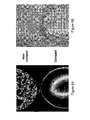
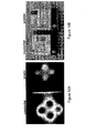
- Figures 2A and 2B show a comparison between NaCl grains of different size as obtained by the method and system in accordance with one embodiment of the invention ( Fig. 2A ) or by a CCD (VIS) camera ( Fig. 2B ).
- Fig. 2A a CCD (VIS) camera
- Fig. 2B a CCD (VIS) camera
- images of NaCl grains of a size of about 2mm in diameter in the upper section of Figs. 2A and 2B displayed are images of grains of the size of about 1mm in diameter.
- difference in size of the NaCl grains can not be distinguished in the CCD images ( Fig. 2B ), they were clearly visualized in the thermographic images produced ( Figs. 2A ).
- the IR signal intensity of the measured powder may be analyzed by applying spatial Fourier transform on the 2D image and analyzing the dominant spatial frequencies. Subsequently, histogram and standard deviation of the 2D image may by applied. It is noted that grains of different size may be distinguished from their spatial frequencies; the larger the grains are, the lower are their dominant spatial frequency and vise versa.
- ACAMOL ® pills (Teva Pharmaceutical Industries Ltd.) were grinded and the formed powder was spread on a flat glass on top of the Black Body radiating source. Water drops of about 10 ⁇ l were splashed onto the spread material to create moisture spots.
- the Black Body radiating source controller was set to a temperature change from 15°C (the Black Body initial temperature) to 20°C using a temperature step function and the image was captured 10 seconds after applying the heat target of 20°C (the heat pulse) to the controller.
- a cooled InSb detector in the 3-5 ⁇ m wavelength range was used to produce an IR image of the detected samples.
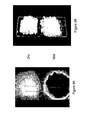
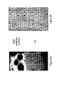
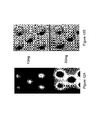
- Figures 3A and 3B show a comparison between images of dry and moisture containing ACAMOL ® powder as obtained by thermography, according to an embodiment of the invention ( Fig. 3A ) or by the use of a CCD (VIS) camera ( Fig. 3B ).
- Fig. 3A images taken for dry powder
- Fig. 3B images of moisture-containing powder.
- the difference in moisture content vs. dry powder cannot be observed by the images obtained using the CCD camera ( Fig. 3B )
- this difference is clearly evident from the thermographic images, showing in the lower section of Fig. 3A darker spots representing the wetted areas within the material which are absent from the dry ACAMOL ® powder (upper section of Fig. 3A ).
- the signal intensity of the measured ACAMOL ® powder may be further analyzed by applying spatial Fourier transform on the 2D image and analyzing the dominant spatial frequencies. Subsequently band pass filters may be applied on the 2D Fourier transform to acquire the humidity spots coordinates. It is noted that wet area is characterized by a higher STD value relative to dry area. The moisture may be detected accordingly.
- Two ACAMOL ® pills were grinded and blended with either about 200 ⁇ l or about 50 ⁇ l of water. The two blends were spread on a flat glass on top of the Black Body radiating source.
- the Black Body radiating source controller was set to a temperature change from 15°C (the Black Body initial temperature) to 20°C using a temperature step function and the image was captured 10 seconds after applying the heat target of 20°C (the heat pulse) to the controller.
- a cooled InSb detector in the 3-5 ⁇ m wavelength range was used to produce an IR image of the detected samples. The resulted images were visually analyzed.
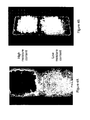
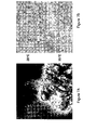
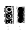
- Figures 4A and 4B provide a comparison between images of ACAMOL ® powder of high and low moisture content, where Fig. 4A display thermographic images obtained in accordance with the invention and Fig. 4B display images obtained by a CCD (VIS) camera. Specifically, in the upper section of Figs. 4A and 4B displayed are images of ACAMOL ® powder which were significantly wetted; in the lower section of Figs. 4A and 4B displayed are images of ACAMOL ® powder which, relatively to the powder in the upper section of Figs. 4A and 4B , were only slightly wetted.
- thermographic images showing in the lower section of Fig. 4A dark spots, representing the wetted powder, while the powder in the upper section of Fig. 4A is completely dark, being indicative that essentially the entire powder is wet.
- the present example thus provides evidence that moisture content of a material can be detected in accordance with the invention and therefore the method of the invention may be applicable for determing quality of process where level of humidity or moisture content are crucial.
- the present example also provides evidence for applicability of the invention for assuring storage conditions and quality when dry conditions are required.
- EXAMPLE 4 Moisture content monitoring (Corn flour powder with under surface moisture spots).
- a hand full amount of corn flour was spread on a flat glass on top of the Black Body radiating source. Water drops of about 50 ⁇ l were splashed onto the material to create moisture spots. The wet spots were covered with an amount of dry corn flour powder (the amount sufficient to cover the wetted spots).
- the Black Body radiating source controller was set to a temperature change from 15°C (the Black Body initial temperature) to 20°C using a temperature step function and the image was captured 10 seconds after applying the heat target of 20°C (the heat pulse) to the controller.
- a cooled InSb detector in the 3-5 ⁇ m wavelength range was used to produce an IR image of the detected samples.
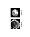
- Figures 5A and 5B provide a comparison between images of corn flour powder of different moisture content, where Fig. 5A display thermographic images obtained in accordance with the invention and Fig. 5B display images obtained by a CCD (VIS) camera. Specifically, in the upper section of Figs. 5A and 5B displayed are images of corn flour containing under surface moisture spots; in the lower section of Figs. 5A and 5B displayed are images of dry corn flour powder.
- CCD CCD
- the resulted images were visually analyzed.
- Spatial Fourier transform may be applied on the 2D image and the dominant spatial frequencies may be analyzed.
- band pass filters may be applied on the 2D Fourier transform to acquire the humidity spots coordinates followed by applying a 2D spatial derivation kernel in order to recognize spots boundaries (edge detection).
- Examples 2 to 4 provide proof of concept for the method and the system of the invention by allowing the "coloring" of different moisture containing areas in samples under examination.
- the "coloring" in these specific examples is related to the difference in the water content of the samples which is resulted in different IR radiation intensities.
- the method and system of the invention may be therefore used to monitor blending uniformity between two or more samples which are differ in their degree of humidity.
- a hand full amount of corn flour powder was manually pressed to create a smooth compact layer of material on a flat glass and placed on top of the Black Body radiating source.
- the Black Body radiating source controller was set to a temperature change from 15°C (the Black Body initial temperature) to 20°C using a temperature step function and the image was captured 10 seconds after applying the heat target of 20°C (the heat pulse) to the controller.
- a cooled InSb detector in the 3-5 ⁇ m wavelength range was used to produce an IR image of the detected samples.
- Figures 6A and 6B show a comparison between corn flour powder of different morphology as obtained by the method and system in accordance with one embodiment of the invention ( Fig. 6A ) or by a CCD (VIS) camera ( Fig. 6B ).
- Fig. 6A a CCD (VIS) camera
- Fig. 6B a CCD (VIS) camera
- images of non-compacted corn flour in the upper section of Figs. 6A and 6B displayed are images of non-compacted corn flour
- the lower section of Figs. 6A and 6B displayed are images of compacted corn flour.
- the compact and non-compact corn flour can be visually distinguished in the CCD images ( Fig. 6B ), as well as in the thermographic images ( Fig. 6A ).
- images were visually analyzed, they may also be further processed. Without being limited thereto, further processing may comprise a histogram and a standard deviation of the 2D image followed by applying spatial Fourier transform on the 2D image and analyzing the dominant spatial frequencies.
- a 2D spatial derivation kernel may by applied in order to recognize spots boundaries (edge detection).
- thermographic images were captured 10 sec after the samples were placed on the Black Body radiating source.
- a cooled InSb detector in the 3-5 ⁇ m wavelength range was used to produce an IR image of the detected samples.
- FIGs. 7A and 7B show a comparison between corn flour powder at different temperatures as obtained by the method and system in accordance with one embodiment of the invention ( Fig. 7A ) or by a CCD (VIS) camera ( Fig. 7B ).
- Fig. 7A a CCD (VIS) camera
- Fig. 7B a CCD (VIS) camera
- Fig. 7A and 7B displayed in the upper section of Figs. 7A and 7B displayed are images of corn flour powder at 20°C
- the lower section of Figs. 7A and 7B displayed are images of corn flour powder at 25°C. While no differences are observed in the CCD images of the powder at the two temperatures ( Fig. 7B ), the difference between the images are clearly visualized in the thermographic images produced ( Figs. 7A ).
- the specific example indicates the ability of the method and system of the invention to "color" the detected samples by means of heating or cooling. Specifically, the difference in the temperatures of the samples resulted in different intensities of the IR radiation of the detected samples. Hence, the method and system of the invention may be used to monitor the degree to which samples of various temperatures are blended.
- Hot air was blown on the Black Body radiating source using a fan.
- the hot air was monitored by the system of the invention.
- Figures 8A and 8B show a comparison between images of hot air distribution obtained in accordance with an embodiment of the invention ( Fig. 8A ) or by the use of a CCD (VIS) camera ( Fig. 8B ). It can be clearly seen that while air can not be captured by the CCD camera ( Fig. 8B ), hot air distribution can be visualized in the thermographic image produced ( Fig. 8A ). Thermography may be therefore used in real time as an indicative of the degree of homogeneity of the hot air flow for example in heating/drying/baking processes in which uniform air flow is necessary in order to achieve a uniform product. Optimization or adjustment of such processes can be thereby achieved.
- EXAMPLE 8 Powder identification (CIALIS ® vs. Fake powder).
- the Black Body radiating source controller was set to a temperature change from 15°C (the Black Body initial temperature) to 20°C using a temperature step function and the image was captured 10 seconds after applying the heat target of 20°C (the heat pulse) to the controller.
- a cooled InSb detector in the 3-5 ⁇ m wavelength range was used to produce an IR image of the detected samples.
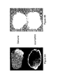
- Figures 9A and 9B show a comparison between CIALIS ® genuine powder and a counterfeit powder as obtained by the method and system in accordance with one embodiment of the invention ( Fig. 9A ) or by a CCD (VIS) camera ( Fig. 9B ).
- Fig. 9A images of genuine powder
- Fig. 9B images of counterfeit powder.
- genuine and fake powder can not be distinguished in the CCD images ( Fig. 9B ), they are visually distinguished in the thermographic images produced ( Fig. 9A ).
- EXAMPLE 9 Drug identification (genuine/authentic VIAGRA ® vs. counterfeit product).
- the Black Body radiating source controller was set to a temperature change from 15°C (the black body initial temperature) to 20°C using a temperature step function and the image was captured 10 seconds after applying the heat target of 20 °C (the heat pulse) to the controller.
- An un-cooled VOx detector in the 8-12 ⁇ m wavelength range was used to produce an IR image of the detected samples.
- Figures 10A and 10B show a comparison between genuine VIAGRA ® and a counterfeit VIAGRA ® packages as obtained by the method and system in accordance with one embodiment of the invention ( Fig. 10A ) or by a CCD (VIS) camera ( Fig. 10B ). While genuine and fake VIAGRA ® packages can not be distinguished in the CCD image ( Fig. 10B ), they are visually distinguished in the thermographic image produced ( Fig. 10A ). This example illustrates how the detection of counterfeit products, such as drugs, can be achieved. Examining a suspected counterfeit product may be by comparison to a pre-acquired IR image of the genuine product. The degree of identity may be indicative if the product is genuine or not. The pre-acquired image may be part of a database.
- the above example illustrates the feasibility of the method and system of the invention to determine quality of a product within a closed package.
- EXAMPLE 10 Drug identification by fusion of images (genuine/authentic VIAGRA ® vs. counterfit product).
- thermographic image was captured 10 seconds after the samples were taken off the chamber and placed at room temperature.
- a thermographic long wave bolometric VOx camera and NIR InSb camera was used to produce an IR image of the detected samples.
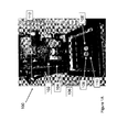
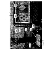
- Figures 11A to 11D show a comparison between genuine VIAGRA ® and a counterfeit VIAGRA ® packages as obtained by a thermographic long wave bolometric VOx camera ( Fig. 11A ), by a NIR InSb camera ( Fig. 11B ), and by a CCD (VIS) camera ( Fig. 11C ). Fusion of the images obtained in Fig.11A and Fig.11B is shown in Fig. 11D . The difference between the authentic and the counterfeit drugs are easily detected in Fig. 11A . It is noted that the Pfizer tag of the authentic drug is observed in the NIR region while the counterfeit tag cannot be observed ( Fig. 11B ). It is further noted that the blue color of counterfeit drug in the VIS spectra is slightly darker then the authentic one ( Fig. 11C ).
- each spectra image of the drugs i.e., VIS, NIR, Thermal (MWIR or LWIR), contributes to some extent for counterfeit detection (or quality assurance).
- the example further illustrates the possibility to apply a fusion image of more than one spectrum to improve the recognition and/or detection ability.
- EXAMPLE 11 Dosage inspection (ENALAPRIL ® 20mg vs. 10 mg).
- a blister of 10mg and a blister of 20mg of the active component Enalapril were placed in a cooling chamber to reduce the temperature of the samples to 5°C. Specifically, the samples were subjected to a step heat function by cooling down in a chamber to a predefined temperature of 5°C followed by removal of samples from the chamber and placement on a sample holder at room temperature.
- thermographic image was captured 10 seconds after the samples were taken off the chamber and placed in room temperature.
- a cooled InSb detector in the 3-5 ⁇ m wavelength range was used to produce an IR image of the detected samples.
- Figs. 12A and 12B show a comparison between images of blisters of the active compound Enalapril at different dosages obtained in accordance with an embodiment of the invention ( Fig. 12A ) or by the use of a CCD (VIS) camera ( Fig. 12B ).
- a CCD (VIS) camera Fig. 12B
- images of 10mg dosage within the blister in the upper section of Figs. 12A and 12B displayed are images of 10mg dosage within the blister; in the lower section of Figs. 12A and 12B displayed are images of 20mg dosage.
- the CCD images of the 10 mg and 20 mg dosage within the blister are identical ( Fig. 12B ), they are visually distinguished in the thermographic images produced ( Figs. 12A ) showing that the invention is applicable also for sealed materials.
- This specific example shows that the method and system of the invention may be used for real time assurance that a packed product includes the product as labeled on the package. While the Example shows the difference between amounts of material (10mg vs. 20mg), the technology of the invention is also applicable to show the presence or absence of material, as shown further below.
- EXAMPLE 12 Dosage inspection (ENALADEX ® 20 mg vs. 10 mg).
- ENALADEX ® (Dexcel LTD) package containing 10 mg and a package containing 20 mg of the active component Enalapril were placed in a cooling chamber to reduce the temperature of the samples to 5°C. Specifically, the samples were subjected to a step heat function by cooling down in a chamber to a predefined temperature of 5°C followed by removal of the samples from the chamber and placement on a sample holder at room temperature.
- thermographic image was captured 10 seconds after the samples were taken off the chamber to room temperature.
- a cooled InSb detector in the 3-5 ⁇ m wavelength range was used to produce an IR image of the detected samples.
- Figures 13A and 13B show a comparison between ENALADEX packages containing 10mg and 20mg of the active component Enalapril obtained in accordance with an embodiment of the invention ( Fig. 13A ) or by the use of a CCD (VIS) camera ( Fig. 13B ).
- a CCD (VIS) camera Fig. 13B
- images of the 10 mg and 20 mg ENALADEX packages produced by the CCD camera display the visual packages with the written information thereon ( Fig. 13B )
- the produced thermographic images display a clear difference between the two packages indicative of the amount of the active material contained therein ( Figs. 13A ).
- EXAMPLE 13 Detection of a broken tablet or a missing tablet in a blister.
- a blister - type package containing tablets was placed in the cooling chamber at 8°C for two minutes. Specifically, the package was subjected to a step heat function by cooling in a chamber at a predefined temperature of 8°C followed by removal of sample from the chamber and placement on a sample holder at room temperature.
- thermographic image was captured 10 seconds after the sample was taken off the chamber to room temperature.
- a cooled InSb detector in the 3-5 ⁇ m wavelength range was used to produce an IR image of the detected samples.
- Figs. 14A and 14B show a comparison between images of blisters obtained in accordance with an embodiment of the invention, using the cooled InSb detector ( Fig. 14A ) or by the use of a CCD (VIS) camera ( Fig. 14B ).
- the upper and lower sections of Figs. 14A and 14B display images of a blister missing a tablet and the lower portions show a broken tablet. While the detection of a missing tablet or a broken tablet cannot be achieved by the CCD images ( Fig. 14B ), the thermographic images produced in accordance with the invention clearly indicate where there is a missing or broken tablet ( Figs. 14A ).
- This Example illustrates that the invention may be used for quality assurance of a packed product, for example, assuring the presence of tablets in a blister, detecting defected tablets such as a broken tablet. Further, the example shows that the invention may be used to identify defects in coating of a tablet or a defected capsule while being contained in a blister.
- EXAMPLE 14 Monitoring liquid level in sealed bottles.
- Two Opaque bottles containing different amount of water were placed in a cooling chamber at 8°C for two minutes. Specifically, the bottles were subjected to a step heat function by cooling down in a chamber to a predefined temperature of 8°C followed by removal of sample from the chamber and placement on a sample holder at room temperature.
- thermographic image was captured 10 seconds after the bottles were taken off the chamber and placed at room temperature.
- a cooled InSb detector in the 3-5 ⁇ m wavelength range was used to produce an IR image of the detected bottles.
- Figures 15A and 15B show a comparison between images of bottles containing different amount of water as obtained in accordance with an embodiment of the invention ( Fig. 15A ) or by the use of a CCD (VIS) camera ( Fig. 15B ). While the content of the two bottles can not be distinguished using a CCD image ( Fig. 15B ), they are visually distinguished in the thermographic image produced, i.e. the different level of water contained in the bottles is clearly detected although the bottles per se are opaque and sealed and their content is invisible to the eye ( Fig. 15A ).
- This example illustrates that the invention is also applicable for detecting content of material within sealed containers.
- the invention is applicable for any type of container, e.g. plastic bottle, dark glass bottle, tape covered bottle etc.
- the detection of liquid level in a container may be improved if the liquid is cooler than the bottle, e.g. detection immediately after introduction of the liquid to the bottle.
- the cooled liquid When the cooled liquid is introduced into the bottle it cools the bottles inner wall only, and only to a temperature of the liquid, while the rest of the bottle stays at its original temperature. This may allow real time assurance that the accurate amount of liquid was introduced into the bottle during the packing in a manufacturing process.
- EXAMPLE 15 Beverages distinguishing (BARKAN vs. SEGAL Cabernet
- a bottle of BARKAN ® dry red wine and two bottles of SEGAL ® Cabernet Sauvignon dry red wine were placed on a Black Body radiation source and heated to 30°C. Specifically, the wine bottles were subjected to a step heat function as they were taken off the Black Body radiation source and placed at ambient room temperature (23°C).
- thermographic image was captured 10 seconds after the bottles were taken off the Black Body radiation source and placed at ambient room temperature (23°C).
- a cooled InSb detector in the 3-5 ⁇ m wavelength range was used to produce an IR image of the detected bottles.
- Figures 16A and 16B show a comparison between images of one bottle of BARKAN ® (right bottle) and two bottles of SEGAL ® (mid and left bottles) Cabernet Sauvignon dry red wine obtained in accordance with an embodiment of the invention ( Fig. 16A ) or by the use of a CCD (VIS) camera ( Fig. 16B ). While the BARKAN ® and SEGAL ® bottles of wine can not be distinguished when using a CCD device ( Fig. 16B ), the difference in the bottles can be easily visualized using the thermographic image ( Fig. 16A ). Thus, this example illustrates how the recognition of various brands of beverages, such as wine bottles, can be achieved by the invention. In other words, the invention should not be limited to pharma industry but also to any product manufacturing process, such as winery.
- EXAMPLE 16 Detection of foreign objects.
- Plastic particles were spread on a plate containing white sugar grains.
- the plate was placed on a Black Body radiation source at a temperature of 25°C.
- the mixture of sugar and plastic particles was subjected to a step cooling function by reducing the temperature of the Black Body radiation source to 15°.
- thermographic image was captured 10 seconds after applying the step function.
- a cooled InSb detector in the 3-5 ⁇ m wavelength range was used to produce an IR image of the detected sample.
- Figures 17A and 17B show a comparison between images of white sugar grains containing plastic particles according to an embodiment of the invention ( Fig. 17A ) or by the use of a CCD (VIS) camera ( Fig. 17B ). While the presence of the plastic particles can not be detected using a CCD camera they can be clearly observed in the thermographic image.
- a CCD VIS
- This example illustrates how the invention may be used for detection of foreign objects in food products.
- Example 17 Detection of authenticity of a package or defects in a package
Landscapes
- Health & Medical Sciences (AREA)
- Physics & Mathematics (AREA)
- Life Sciences & Earth Sciences (AREA)
- Chemical & Material Sciences (AREA)
- Immunology (AREA)
- Pathology (AREA)
- Analytical Chemistry (AREA)
- Biochemistry (AREA)
- General Health & Medical Sciences (AREA)
- General Physics & Mathematics (AREA)
- Engineering & Computer Science (AREA)
- Spectroscopy & Molecular Physics (AREA)
- Food Science & Technology (AREA)
- Medicinal Chemistry (AREA)
- Bioinformatics & Cheminformatics (AREA)
- Biophysics (AREA)
- Molecular Biology (AREA)
- Pharmacology & Pharmacy (AREA)
- Multimedia (AREA)
- Signal Processing (AREA)
- Toxicology (AREA)
- Investigating Or Analyzing Materials Using Thermal Means (AREA)
- Radiation Pyrometers (AREA)
- Investigating Or Analysing Materials By Optical Means (AREA)
- Investigating Materials By The Use Of Optical Means Adapted For Particular Applications (AREA)
Applications Claiming Priority (3)
| Application Number | Priority Date | Filing Date | Title |
|---|---|---|---|
| US20220409P | 2009-02-05 | 2009-02-05 | |
| US26354909P | 2009-11-23 | 2009-11-23 | |
| EP10706756 | 2010-02-04 |
Related Parent Applications (2)
| Application Number | Title | Priority Date | Filing Date |
|---|---|---|---|
| EP10706756 Division | 2009-02-05 | 2010-02-04 | |
| EP10706756.3 Division | 2010-02-04 |
Publications (3)
| Publication Number | Publication Date |
|---|---|
| EP2508882A2 true EP2508882A2 (de) | 2012-10-10 |
| EP2508882A3 EP2508882A3 (de) | 2013-01-02 |
| EP2508882B1 EP2508882B1 (de) | 2016-09-21 |
Family
ID=42124548
Family Applications (1)
| Application Number | Title | Priority Date | Filing Date |
|---|---|---|---|
| EP11177804.9A Not-in-force EP2508882B1 (de) | 2009-02-05 | 2010-02-04 | Verfahren und System zur Bestimmung der Qualität pharmazeutischer Produkte |
Country Status (10)
| Country | Link |
|---|---|
| US (2) | US9008408B2 (de) |
| EP (1) | EP2508882B1 (de) |
| JP (1) | JP5844160B2 (de) |
| KR (1) | KR20110127177A (de) |
| CN (1) | CN102378912A (de) |
| CA (1) | CA2751396A1 (de) |
| IL (1) | IL214452A (de) |
| RU (1) | RU2011135191A (de) |
| SG (1) | SG173204A1 (de) |
| WO (1) | WO2010089744A1 (de) |
Cited By (2)
| Publication number | Priority date | Publication date | Assignee | Title |
|---|---|---|---|---|
| EP2852532B1 (de) | 2012-05-23 | 2017-09-06 | Blueprint Holding B.V. | Verfahren zur qualitätskontrolle und zum verpacken für ein eingehülltes produkt und vorrichtungen zur qualitätskontrolle und zum verpacken für ein eingehülltes produkt |
| WO2020104011A1 (de) | 2018-11-19 | 2020-05-28 | Tera Group Ag | Verfahren und vorrichtung zur klassifizierung einer probe mittels terahertz-spektroskopie |
Families Citing this family (26)
| Publication number | Priority date | Publication date | Assignee | Title |
|---|---|---|---|---|
| WO2010120555A2 (en) | 2009-03-31 | 2010-10-21 | The U.S.A, As Represented By The Secretary,Dpt. Of Health & Human Services | Device and method for detection of counterfeit pharmaceuticals and/or drug packaging |
| US10007920B2 (en) | 2012-12-07 | 2018-06-26 | The United States Of America, As Represented By The Secretary, Department Of Health And Human Services | Device and method for detection of counterfeit pharmaceuticals and/or drug packaging |
| EP2759597A1 (de) * | 2013-01-23 | 2014-07-30 | Sekab E-Technology AB | Verfahrenssteuerung auf Bildanalysebasis von Verfahren zur Herstellung von Zucker aus Lignozellulosebiomasse |
| US9354178B2 (en) * | 2013-03-05 | 2016-05-31 | Smiths Detection Inc. | Transmission raman sample analysis |
| IL226111A (en) * | 2013-05-02 | 2015-11-30 | D I R Technologies Detection Ir Ltd | Thermography-based method, device and product to identify defects in sealing that includes a conductive internal gasket |
| JP5817072B2 (ja) * | 2013-07-04 | 2015-11-18 | 礼之 井上 | 包装容器の内容物の検査方法 |
| US9347899B2 (en) | 2013-12-06 | 2016-05-24 | Rolls-Royce Corporation | Thermographic inspection techniques |
| CN106458420B (zh) * | 2014-06-03 | 2020-02-28 | 株式会社明治 | 容器及容器装经肠营养剂或容器装饮食品和检测制造方法 |
| CN105403675A (zh) * | 2014-09-15 | 2016-03-16 | 南京农业大学 | 一种食品异物检测装置 |
| WO2016060499A1 (ko) | 2014-10-17 | 2016-04-21 | 신용관 | 약품 하이브리드 검사시스템 및 검사방법 |
| KR101531530B1 (ko) * | 2014-12-31 | 2015-06-25 | (주)스타넥스 | 이미지 분석 방법, 장치 및 컴퓨터로 판독가능한 장치 |
| JP6799737B2 (ja) * | 2016-06-28 | 2020-12-16 | 池上通信機株式会社 | 異物検出方法 |
| US10187593B2 (en) | 2016-09-27 | 2019-01-22 | Rxsafe Llc | Verification system for a pharmacy packaging system |
| US11595595B2 (en) | 2016-09-27 | 2023-02-28 | Rxsafe Llc | Verification system for a pharmacy packaging system |
| US20180162535A1 (en) * | 2016-12-08 | 2018-06-14 | Hamilton Sundstrand Corporation | Air distribution system with recirculating zone trim tec |
| CN106779756A (zh) * | 2017-01-06 | 2017-05-31 | 夏明高 | 一种能让人们知道产品真实质量的方法 |
| JP6964305B2 (ja) * | 2017-03-17 | 2021-11-10 | 池上通信機株式会社 | パッケージ品の内容物検査方法および検査装置 |
| JP6914753B2 (ja) * | 2017-07-03 | 2021-08-04 | 池上通信機株式会社 | パッケージ品の内容物検査方法および検査装置 |
| GB201715860D0 (en) | 2017-09-29 | 2017-11-15 | Univ Oxford Innovation Ltd | Methods of sensing, probe apparatus, storage device |
| US10656081B2 (en) * | 2017-10-18 | 2020-05-19 | The Boeing Company | Synchronized phased array and infrared detector system for moisture detection |
| JP6539371B1 (ja) * | 2018-03-14 | 2019-07-03 | Ckd株式会社 | 検査装置、ptp包装機、及び、検査方法 |
| CN110340863B (zh) | 2018-04-08 | 2023-02-17 | AIrobot株式会社 | 自主移动搬运机器人 |
| CN111060473B (zh) * | 2020-01-15 | 2021-06-25 | 王丽娟 | 一种食品质量分析检测装置 |
| US12134494B2 (en) | 2022-01-03 | 2024-11-05 | Rxsafe, Llc | Verification system for a pharmacy packaging system |
| US20240071072A1 (en) * | 2022-08-31 | 2024-02-29 | X Development Llc | Microplastics detector sensor coupling and data training |
| US12593116B2 (en) * | 2023-12-18 | 2026-03-31 | Electronics And Telecommunications Research Institute | Imaging measurement device using gas absorption in the mid-infrared band and operating method of imaging measurement device |
Citations (5)
| Publication number | Priority date | Publication date | Assignee | Title |
|---|---|---|---|---|
| DE19629101A1 (de) | 1996-07-19 | 1998-01-22 | Barnickel Wolfgang | Einheit für die berührungslose Erkennung, Inspektion und Kontrolle von Verpackungen und deren Inhalten, mittels temperaturempfindlicher Sensoren (Pyrosensoren) und Infrarotkameras sowie für die Erkennung und Ausschleusung fehlerhafter Behältnisse |
| DE19908410A1 (de) | 1998-10-27 | 2000-05-11 | Klaus Herbst Consulting Servic | Verfahren und Vorrichtung zur Echtheitsprüfung von Objekten |
| US6395538B1 (en) | 1999-07-16 | 2002-05-28 | Human Genome Sciences, Inc. | Method and system for providing real-time, in situ biomanufacturing process monitoring and control in response to IR spectroscopy |
| US6853447B2 (en) | 2001-02-12 | 2005-02-08 | Analytical Spectral Devices, Inc. | System and method for the collection of spectral image data |
| US7126685B1 (en) | 2003-01-02 | 2006-10-24 | Southwest Sciences Incorporated | Optical absorbance sensitivity and reliability improvement via rotation of sample container |
Family Cites Families (85)
| Publication number | Priority date | Publication date | Assignee | Title |
|---|---|---|---|---|
| SU534120A1 (ru) | 1974-12-20 | 1997-11-20 | С.А. Демидов | Терморадиометр |
| US4026656A (en) | 1975-09-02 | 1977-05-31 | Owens-Illinois, Inc. | Stone detector |
| US4280631A (en) | 1980-03-10 | 1981-07-28 | Owens-Illinois, Inc. | Safety closure and container with snap cap liner |
| SU1193555A1 (ru) | 1984-05-16 | 1985-11-23 | Тамбовский институт химического машиностроения | Способ комплексного определени теплофизических характеристик материалов без нарушени их целостности |
| US4795906A (en) | 1985-12-13 | 1989-01-03 | Lockheed Corporation | Apparatus and system for thermographic identification of parts |
| JP2599282B2 (ja) * | 1988-03-25 | 1997-04-09 | 科学技術庁無機材質研究所長 | 熱定数測定法 |
| DE3819531A1 (de) | 1988-06-08 | 1989-12-14 | Reiner Dipl Phys Szepan | Signalprozess- und betriebstechnik zur laserspektroskopischen mengenbestimmung von ammoniak in gasgemischen |
| DE3820862A1 (de) | 1988-06-21 | 1989-12-28 | Soelter Hans Joachim Dipl Phys | Verfahren und vorrichtung zur kontaktlosen untersuchung von oberflaechen und inneren strukturen eines festen pruefkoerpers |
| JPH0257533A (ja) | 1988-08-22 | 1990-02-27 | Taiyo Fishery Co Ltd | 密閉容器のリーク検査方法 |
| NO911492D0 (no) | 1988-10-19 | 1991-04-16 | Lumetech As | Fremgangsmaate for aa detektere mark i kjoett. |
| SU1635099A1 (ru) | 1989-04-20 | 1991-03-15 | Институт технической теплофизики АН УССР | Способ комплексного определени теплофизических характеристик материалов |
| US5417494A (en) * | 1992-05-01 | 1995-05-23 | Exid, Inc. | Contactless testing of electronic materials and devices using microwaves |
| US5458418A (en) * | 1993-07-02 | 1995-10-17 | Her Majesty The Queen In Right Of Canada, As Represented By The Minister Of Agriculture | Method for detecting poor meat quality in live animals |
| US5357112A (en) * | 1993-07-14 | 1994-10-18 | Mississippi State University: Forest Products Laboratory | Method for determining the presence of knots or voids in wood |
| GB9425232D0 (en) | 1994-12-14 | 1995-02-08 | Secr Defence | Method of authenticating watermarked paper |
| JPH08184571A (ja) | 1994-12-28 | 1996-07-16 | Mitsubishi Heavy Ind Ltd | 容器口封材のシール部検査方法及び装置 |
| US5818951A (en) * | 1995-10-13 | 1998-10-06 | Infrared Service Corporation | Methods and related apparatus for generating thermographic survey images |
| JPH09138205A (ja) * | 1995-11-15 | 1997-05-27 | Agency Of Ind Science & Technol | 赤外線サーモグラフィによる材料の欠陥検出方法 |
| US5646405A (en) * | 1995-11-29 | 1997-07-08 | Lawson-Hemphill, Inc. | Method of detecting contaminants in cotton fibers |
| JPH09297114A (ja) | 1996-05-08 | 1997-11-18 | Mitsubishi Heavy Ind Ltd | プラスチック材質判別法及びその装置 |
| DK173406B1 (da) | 1996-07-05 | 2000-09-25 | Anders Sten Wedell | Fremgangsmåde ved og apparat til måling af uforbrændt kulstof i flyveaske |
| WO1998003847A2 (en) | 1996-07-19 | 1998-01-29 | Mills Alexander K | Device for noninvasive determination of blood parameters |
| EP1669738A3 (de) | 1996-10-09 | 2007-12-12 | Symyx Technologies, Inc. | Infrarotspektroskopie und Abbildung von Bibliotheken |
| JPH10278910A (ja) * | 1997-04-07 | 1998-10-20 | Jeol Ltd | サーモグラフィによる製品検査装置 |
| JP3517079B2 (ja) | 1997-05-14 | 2004-04-05 | クノール食品株式会社 | 高周波アルミシールの非接触検査法 |
| RU2125259C1 (ru) | 1997-10-14 | 1999-01-20 | Акционерное общество открытого типа "Научно-исследовательский технологический институт" | Устройство для определения содержания нерастворенной воды в технических жидкостях |
| US6013915A (en) | 1998-02-10 | 2000-01-11 | Philip Morris Incorporated | Process control by transient thermography |
| CA2267586A1 (en) | 1998-04-16 | 1999-10-16 | Tecnar Automation Ltee | Detection of near surface defects by reversed thermography |
| WO1999060630A1 (en) * | 1998-05-15 | 1999-11-25 | Glaxo Group Limited | Infrared thermography |
| SE512098C2 (sv) | 1998-05-19 | 2000-01-24 | Agrovision Ab | Koncentrationsbestämning av en komponent i en blandning av minst två komponenter |
| US6297508B1 (en) * | 1998-08-10 | 2001-10-02 | Cryovac Inc. | Method of determining authenticity of a packaged product |
| US6224699B1 (en) | 1998-11-12 | 2001-05-01 | Kimberly-Clark Worldwide, Inc. | Infrared imaging to detect components on personal care articles |
| AU4691400A (en) | 1999-05-03 | 2000-11-17 | Pictuality, Inc. | Image analysis process |
| WO2000074504A1 (en) | 1999-06-08 | 2000-12-14 | Japan Tobacco Inc. | Apparatus for detecting foreign matter in raw material and method of detecting the same |
| US7227148B2 (en) | 1999-06-08 | 2007-06-05 | Japan Tobacco Inc. | Apparatus for detecting impurities in material and detecting method therefor |
| US6751342B2 (en) * | 1999-12-02 | 2004-06-15 | Thermal Wave Imaging, Inc. | System for generating thermographic images using thermographic signal reconstruction |
| EP1719970A3 (de) | 2000-03-01 | 2009-11-18 | Plastic Technologies, Inc. | Verfahren und Vorrichtung zum Messen der Wanddicke eines Plastikbehälters |
| US6542849B2 (en) * | 2001-01-19 | 2003-04-01 | The University Of Chicago | Method for determining defect depth using thermal imaging |
| JP2002211058A (ja) | 2001-01-24 | 2002-07-31 | Matsushita Electric Ind Co Ltd | 被印刷物検出装置 |
| FI114741B (fi) * | 2001-05-11 | 2004-12-15 | Metso Automation Oy | Lämpökuvaukseen perustuva laadun- ja kunnonvalvontamenetelmä |
| WO2003060443A1 (en) | 2001-12-21 | 2003-07-24 | Spectral Dimensions, Inc. | Spectrometric process monitoring |
| WO2003062809A1 (en) | 2002-01-23 | 2003-07-31 | Marena Systems Corporation | Infrared thermography for defect detection and analysis |
| US6771369B2 (en) | 2002-03-12 | 2004-08-03 | Analytical Spectral Devices, Inc. | System and method for pharmacy validation and inspection |
| JP2003307505A (ja) | 2002-04-15 | 2003-10-31 | Nec San-Ei Instruments Ltd | サーモグラフィによる非接触検査装置及びその非接触検査方法 |
| MXPA04011477A (es) * | 2002-05-20 | 2005-08-15 | Sun Chemical Corp | Sistema de imagenes de seguridad. |
| US20040023397A1 (en) | 2002-08-05 | 2004-02-05 | Rakesh Vig | Tamper-resistant authentication mark for use in product or product packaging authentication |
| US7582872B2 (en) * | 2002-10-11 | 2009-09-01 | Malvern Instruments Incorporated | Volumetric spectral imaging |
| AU2003207120A1 (en) | 2002-10-24 | 2004-05-13 | Chromic Co., Ltd. | Temperature indicating display device |
| US7218395B2 (en) | 2003-04-16 | 2007-05-15 | Optopo Inc. | Rapid pharmaceutical identification and verification system |
| KR100509298B1 (ko) | 2003-05-31 | 2005-08-22 | 한국과학기술연구원 | 무기질 박막이 코팅된 직접메탄올 연료전지용 복합고분자 전해질막의 제조 방법 |
| JP2007502978A (ja) | 2003-08-21 | 2007-02-15 | グローバル セキュリティー デバイシーズ リミテッド | 隠匿物を検出する方法 |
| WO2005040739A2 (en) | 2003-10-22 | 2005-05-06 | Softmax, Inc. | System and method for spectral analysis |
| US7028723B1 (en) | 2003-11-03 | 2006-04-18 | Alouani Ali Tahar | Apparatus and method for automatic prescription verification |
| US8543411B2 (en) | 2003-11-05 | 2013-09-24 | United Parcel Service Of America, Inc. | Systems and methods for detecting counterfeit pharmaceutical drugs at the point of retail sale |
| US7351442B2 (en) * | 2003-12-19 | 2008-04-01 | Agfa-Gevaert | Method of preparing storage phosphors from dedicated precursors |
| US20050169511A1 (en) | 2004-01-30 | 2005-08-04 | Cummins-Allison Corp. | Document processing system using primary and secondary pictorial image comparison |
| US7771777B2 (en) | 2004-06-14 | 2010-08-10 | Acushnet Company | Apparatus and method for inspecting golf balls using infrared radiation |
| WO2006012194A1 (en) * | 2004-06-24 | 2006-02-02 | Ircon, Inc. | Method and apparatus for monitoring and detecting defects in plastic package sealing |
| US7046359B2 (en) | 2004-06-30 | 2006-05-16 | Chemimage Corporation | System and method for dynamic chemical imaging |
| US20060024746A1 (en) | 2004-07-14 | 2006-02-02 | Artann Laboratories, Inc. | Methods and devices for optical monitoring and rapid analysis of drying droplets |
| ITPR20040056A1 (it) | 2004-08-04 | 2004-11-04 | Procomac Spa | Procedimento per valutare la sigillatura di un contenitore. |
| US7164146B2 (en) * | 2004-10-22 | 2007-01-16 | Northrop Grumman Corporation | System for detecting structural defects and features utilizing blackbody self-illumination |
| US7462809B2 (en) * | 2004-10-22 | 2008-12-09 | Northrop Grumman Corporation | Spectral filter system for infrared imaging of substrates through coatings |
| RU48453U1 (ru) | 2004-12-24 | 2005-10-27 | Красноперов Андрей Геннадьевич | Устройство для определения содержания гумуса в почве |
| JP4206997B2 (ja) * | 2004-12-24 | 2009-01-14 | 株式会社コンステック | 外装改善計画システム |
| WO2006090353A1 (en) | 2005-02-23 | 2006-08-31 | Global Security Devices Ltd. | System and method for detecting concealed objects |
| JP2006258551A (ja) | 2005-03-16 | 2006-09-28 | Ishizuka Glass Co Ltd | 液内異物検査装置 |
| JP2006351669A (ja) * | 2005-06-14 | 2006-12-28 | Mitsubishi Electric Corp | 赤外検査装置および赤外検査方法ならびに半導体ウェハの製造方法 |
| RU2301415C2 (ru) | 2005-08-01 | 2007-06-20 | Гоу Впо "Тюменский Государственный Университет" | Устройство для идентификации и контроля качества жидкостей |
| WO2007041579A2 (en) * | 2005-10-03 | 2007-04-12 | Sun Chemical Corporation | Security pigments and the process of making thereof |
| JP2007108110A (ja) * | 2005-10-17 | 2007-04-26 | Matsushita Electric Ind Co Ltd | 基板の検査方法および基板の検査装置 |
| US7730797B1 (en) * | 2005-11-01 | 2010-06-08 | Hewlett-Packard Development Company, L.P. | Authenticating a package using noise level |
| US7239974B2 (en) | 2005-11-21 | 2007-07-03 | Viaspace Security Inc. | Explosive device detection based on differential emissivity |
| US8581975B2 (en) | 2006-06-16 | 2013-11-12 | Worcester Polytechnic Institute | Infrared defect detection system and method for the evaluation of powdermetallic compacts |
| EP1882579A1 (de) | 2006-07-27 | 2008-01-30 | Soudronic AG | Verfahren und Vorrichtung zur Herstellung von mit einer Siegelnaht versehenen Gegenständen |
| US7840360B1 (en) | 2006-10-26 | 2010-11-23 | Micheels Ronald H | Optical system and method for inspection and characterization of liquids in vessels |
| US7422147B2 (en) * | 2006-12-22 | 2008-09-09 | Walter Steven Rosenbaum | System and method for detecting fraudulent transactions of items having item-identifying indicia |
| US8194920B2 (en) | 2007-02-16 | 2012-06-05 | Ford Global Technologies, Llc | Method and system for detecting objects using far infrared images |
| IL185130A0 (en) * | 2007-08-08 | 2008-01-06 | Semi Conductor Devices An Elbi | Thermal based system and method for detecting counterfeit drugs |
| EP2180744A1 (de) | 2008-10-24 | 2010-04-28 | Mitsubishi Electric R&D Centre Europe B.V. | Verfahren und Vorrichtung zur Ermöglichung des Zugriffs eines mobilen Endgeräts auf ein drahtloses Telekommunikationsnetzwerk |
| WO2010120555A2 (en) | 2009-03-31 | 2010-10-21 | The U.S.A, As Represented By The Secretary,Dpt. Of Health & Human Services | Device and method for detection of counterfeit pharmaceuticals and/or drug packaging |
| US20120281096A1 (en) | 2011-05-02 | 2012-11-08 | Honeywell-Enraf B.V. | Storage tank inspection system and method |
| US20120279968A1 (en) | 2011-05-05 | 2012-11-08 | The Andwin Corp. | Child Resistant Dosing Adapter Cap |
| WO2013057731A1 (en) | 2011-10-17 | 2013-04-25 | D.I.R. Technologies (Detection Ir) Ltd. | Methods of detecting the presence of microorganisms in a sample |
| EP2453225A3 (de) | 2011-12-15 | 2012-06-27 | Finatec Holding AG | Verfahren und System zum Prüfen von mit einer Gasbarriere-Schicht versehenen Gegenständen |
-
2010
- 2010-02-04 KR KR1020117020511A patent/KR20110127177A/ko not_active Ceased
- 2010-02-04 EP EP11177804.9A patent/EP2508882B1/de not_active Not-in-force
- 2010-02-04 RU RU2011135191/15A patent/RU2011135191A/ru not_active Application Discontinuation
- 2010-02-04 US US13/147,867 patent/US9008408B2/en not_active Expired - Fee Related
- 2010-02-04 SG SG2011055811A patent/SG173204A1/en unknown
- 2010-02-04 CA CA2751396A patent/CA2751396A1/en not_active Abandoned
- 2010-02-04 CN CN2010800153897A patent/CN102378912A/zh active Pending
- 2010-02-04 JP JP2011548845A patent/JP5844160B2/ja not_active Expired - Fee Related
- 2010-02-04 WO PCT/IL2010/000102 patent/WO2010089744A1/en not_active Ceased
-
2011
- 2011-08-04 IL IL214452A patent/IL214452A/en not_active IP Right Cessation
-
2015
- 2015-03-20 US US14/663,498 patent/US20150192525A1/en not_active Abandoned
Patent Citations (5)
| Publication number | Priority date | Publication date | Assignee | Title |
|---|---|---|---|---|
| DE19629101A1 (de) | 1996-07-19 | 1998-01-22 | Barnickel Wolfgang | Einheit für die berührungslose Erkennung, Inspektion und Kontrolle von Verpackungen und deren Inhalten, mittels temperaturempfindlicher Sensoren (Pyrosensoren) und Infrarotkameras sowie für die Erkennung und Ausschleusung fehlerhafter Behältnisse |
| DE19908410A1 (de) | 1998-10-27 | 2000-05-11 | Klaus Herbst Consulting Servic | Verfahren und Vorrichtung zur Echtheitsprüfung von Objekten |
| US6395538B1 (en) | 1999-07-16 | 2002-05-28 | Human Genome Sciences, Inc. | Method and system for providing real-time, in situ biomanufacturing process monitoring and control in response to IR spectroscopy |
| US6853447B2 (en) | 2001-02-12 | 2005-02-08 | Analytical Spectral Devices, Inc. | System and method for the collection of spectral image data |
| US7126685B1 (en) | 2003-01-02 | 2006-10-24 | Southwest Sciences Incorporated | Optical absorbance sensitivity and reliability improvement via rotation of sample container |
Cited By (2)
| Publication number | Priority date | Publication date | Assignee | Title |
|---|---|---|---|---|
| EP2852532B1 (de) | 2012-05-23 | 2017-09-06 | Blueprint Holding B.V. | Verfahren zur qualitätskontrolle und zum verpacken für ein eingehülltes produkt und vorrichtungen zur qualitätskontrolle und zum verpacken für ein eingehülltes produkt |
| WO2020104011A1 (de) | 2018-11-19 | 2020-05-28 | Tera Group Ag | Verfahren und vorrichtung zur klassifizierung einer probe mittels terahertz-spektroskopie |
Also Published As
| Publication number | Publication date |
|---|---|
| US20150192525A1 (en) | 2015-07-09 |
| JP2012517013A (ja) | 2012-07-26 |
| US20110293166A1 (en) | 2011-12-01 |
| CN102378912A (zh) | 2012-03-14 |
| RU2011135191A (ru) | 2013-03-10 |
| US9008408B2 (en) | 2015-04-14 |
| WO2010089744A1 (en) | 2010-08-12 |
| CA2751396A1 (en) | 2010-08-12 |
| IL214452A0 (en) | 2011-09-27 |
| EP2508882A3 (de) | 2013-01-02 |
| IL214452A (en) | 2017-08-31 |
| JP5844160B2 (ja) | 2016-01-13 |
| EP2508882B1 (de) | 2016-09-21 |
| KR20110127177A (ko) | 2011-11-24 |
| SG173204A1 (en) | 2011-08-29 |
Similar Documents
| Publication | Publication Date | Title |
|---|---|---|
| US9008408B2 (en) | Method and system for determining the quality of pharmaceutical products | |
| CN101815935B (zh) | 用于检测假药的基于温度记录法的系统和方法 | |
| US8842266B2 (en) | Pharmaceutical mixture evaluation | |
| US12306065B2 (en) | Container leakage detection using thermal imaging | |
| WO2015140797A2 (en) | Method and system for determining package integrity | |
| US11568532B2 (en) | Methods and systems for thermal imaging of moving objects | |
| WO2014195943A1 (en) | An infra-red based method and system for determining integrity of a product | |
| CN111492229A (zh) | 用于无损识别包装好的药物的系统和方法 | |
| US20060244954A1 (en) | System and method for inspecting packaging quality of a packaged food product | |
| WO2015013270A1 (en) | Spectroscopy detection system and method for material identification | |
| Gowen et al. | Influence of polymer packaging films on hyperspectral imaging data in the visible–near-infrared (450–950 nm) wavelength range | |
| US20080032412A1 (en) | Pharmaceutical mixture evaluation | |
| HK1146117B (en) | Thermography based system and method for detecting counterfeit drugs | |
| Lewis et al. | Near‐Infrared Chemical Imaging for Product and Process Understanding |
Legal Events
| Date | Code | Title | Description |
|---|---|---|---|
| PUAI | Public reference made under article 153(3) epc to a published international application that has entered the european phase |
Free format text: ORIGINAL CODE: 0009012 |
|
| AK | Designated contracting states |
Kind code of ref document: A2 Designated state(s): AT BE BG CH CY CZ DE DK EE ES FI FR GB GR HR HU IE IS IT LI LT LU LV MC MK MT NL NO PL PT RO SE SI SK SM TR |
|
| PUAL | Search report despatched |
Free format text: ORIGINAL CODE: 0009013 |
|
| AK | Designated contracting states |
Kind code of ref document: A3 Designated state(s): AT BE BG CH CY CZ DE DK EE ES FI FR GB GR HR HU IE IS IT LI LT LU LV MC MK MT NL NO PL PT RO SE SI SK SM TR |
|
| RIC1 | Information provided on ipc code assigned before grant |
Ipc: G01N 21/35 20060101ALI20121129BHEP Ipc: G01N 33/15 20060101AFI20121129BHEP |
|
| 17P | Request for examination filed |
Effective date: 20130702 |
|
| RBV | Designated contracting states (corrected) |
Designated state(s): AT BE BG CH CY CZ DE DK EE ES FI FR GB GR HR HU IE IS IT LI LT LU LV MC MK MT NL NO PL PT RO SE SI SK SM TR |
|
| 17Q | First examination report despatched |
Effective date: 20130726 |
|
| GRAP | Despatch of communication of intention to grant a patent |
Free format text: ORIGINAL CODE: EPIDOSNIGR1 |
|
| RIN1 | Information on inventor provided before grant (corrected) |
Inventor name: WEINSTEIN, YOAV Inventor name: SINBAR, ERAN |
|
| INTG | Intention to grant announced |
Effective date: 20160404 |
|
| RAP1 | Party data changed (applicant data changed or rights of an application transferred) |
Owner name: D.I.R. TECHNOLOGIES (DETECTION IR) LTD. |
|
| GRAS | Grant fee paid |
Free format text: ORIGINAL CODE: EPIDOSNIGR3 |
|
| GRAA | (expected) grant |
Free format text: ORIGINAL CODE: 0009210 |
|
| AK | Designated contracting states |
Kind code of ref document: B1 Designated state(s): AT BE BG CH CY CZ DE DK EE ES FI FR GB GR HR HU IE IS IT LI LT LU LV MC MK MT NL NO PL PT RO SE SI SK SM TR |
|
| REG | Reference to a national code |
Ref country code: GB Ref legal event code: FG4D |
|
| REG | Reference to a national code |
Ref country code: CH Ref legal event code: EP |
|
| REG | Reference to a national code |
Ref country code: AT Ref legal event code: REF Ref document number: 831454 Country of ref document: AT Kind code of ref document: T Effective date: 20161015 |
|
| REG | Reference to a national code |
Ref country code: IE Ref legal event code: FG4D |
|
| REG | Reference to a national code |
Ref country code: DE Ref legal event code: R096 Ref document number: 602010036676 Country of ref document: DE |
|
| REG | Reference to a national code |
Ref country code: CH Ref legal event code: NV Representative=s name: SERVOPATENT GMBH, CH |
|
| REG | Reference to a national code |
Ref country code: LT Ref legal event code: MG4D Ref country code: NL Ref legal event code: MP Effective date: 20160921 |
|
| PG25 | Lapsed in a contracting state [announced via postgrant information from national office to epo] |
Ref country code: FI Free format text: LAPSE BECAUSE OF FAILURE TO SUBMIT A TRANSLATION OF THE DESCRIPTION OR TO PAY THE FEE WITHIN THE PRESCRIBED TIME-LIMIT Effective date: 20160921 Ref country code: NO Free format text: LAPSE BECAUSE OF FAILURE TO SUBMIT A TRANSLATION OF THE DESCRIPTION OR TO PAY THE FEE WITHIN THE PRESCRIBED TIME-LIMIT Effective date: 20161221 Ref country code: LT Free format text: LAPSE BECAUSE OF FAILURE TO SUBMIT A TRANSLATION OF THE DESCRIPTION OR TO PAY THE FEE WITHIN THE PRESCRIBED TIME-LIMIT Effective date: 20160921 |
|
| REG | Reference to a national code |
Ref country code: AT Ref legal event code: MK05 Ref document number: 831454 Country of ref document: AT Kind code of ref document: T Effective date: 20160921 |
|
| PG25 | Lapsed in a contracting state [announced via postgrant information from national office to epo] |
Ref country code: NL Free format text: LAPSE BECAUSE OF FAILURE TO SUBMIT A TRANSLATION OF THE DESCRIPTION OR TO PAY THE FEE WITHIN THE PRESCRIBED TIME-LIMIT Effective date: 20160921 Ref country code: SE Free format text: LAPSE BECAUSE OF FAILURE TO SUBMIT A TRANSLATION OF THE DESCRIPTION OR TO PAY THE FEE WITHIN THE PRESCRIBED TIME-LIMIT Effective date: 20160921 Ref country code: LV Free format text: LAPSE BECAUSE OF FAILURE TO SUBMIT A TRANSLATION OF THE DESCRIPTION OR TO PAY THE FEE WITHIN THE PRESCRIBED TIME-LIMIT Effective date: 20160921 Ref country code: GR Free format text: LAPSE BECAUSE OF FAILURE TO SUBMIT A TRANSLATION OF THE DESCRIPTION OR TO PAY THE FEE WITHIN THE PRESCRIBED TIME-LIMIT Effective date: 20161222 |
|
| PG25 | Lapsed in a contracting state [announced via postgrant information from national office to epo] |
Ref country code: EE Free format text: LAPSE BECAUSE OF FAILURE TO SUBMIT A TRANSLATION OF THE DESCRIPTION OR TO PAY THE FEE WITHIN THE PRESCRIBED TIME-LIMIT Effective date: 20160921 |
|
| PG25 | Lapsed in a contracting state [announced via postgrant information from national office to epo] |
Ref country code: SM Free format text: LAPSE BECAUSE OF FAILURE TO SUBMIT A TRANSLATION OF THE DESCRIPTION OR TO PAY THE FEE WITHIN THE PRESCRIBED TIME-LIMIT Effective date: 20160921 Ref country code: PL Free format text: LAPSE BECAUSE OF FAILURE TO SUBMIT A TRANSLATION OF THE DESCRIPTION OR TO PAY THE FEE WITHIN THE PRESCRIBED TIME-LIMIT Effective date: 20160921 Ref country code: BE Free format text: LAPSE BECAUSE OF FAILURE TO SUBMIT A TRANSLATION OF THE DESCRIPTION OR TO PAY THE FEE WITHIN THE PRESCRIBED TIME-LIMIT Effective date: 20160921 Ref country code: ES Free format text: LAPSE BECAUSE OF FAILURE TO SUBMIT A TRANSLATION OF THE DESCRIPTION OR TO PAY THE FEE WITHIN THE PRESCRIBED TIME-LIMIT Effective date: 20160921 Ref country code: PT Free format text: LAPSE BECAUSE OF FAILURE TO SUBMIT A TRANSLATION OF THE DESCRIPTION OR TO PAY THE FEE WITHIN THE PRESCRIBED TIME-LIMIT Effective date: 20170123 Ref country code: IS Free format text: LAPSE BECAUSE OF FAILURE TO SUBMIT A TRANSLATION OF THE DESCRIPTION OR TO PAY THE FEE WITHIN THE PRESCRIBED TIME-LIMIT Effective date: 20170121 Ref country code: AT Free format text: LAPSE BECAUSE OF FAILURE TO SUBMIT A TRANSLATION OF THE DESCRIPTION OR TO PAY THE FEE WITHIN THE PRESCRIBED TIME-LIMIT Effective date: 20160921 Ref country code: CZ Free format text: LAPSE BECAUSE OF FAILURE TO SUBMIT A TRANSLATION OF THE DESCRIPTION OR TO PAY THE FEE WITHIN THE PRESCRIBED TIME-LIMIT Effective date: 20160921 Ref country code: SK Free format text: LAPSE BECAUSE OF FAILURE TO SUBMIT A TRANSLATION OF THE DESCRIPTION OR TO PAY THE FEE WITHIN THE PRESCRIBED TIME-LIMIT Effective date: 20160921 |
|
| REG | Reference to a national code |
Ref country code: DE Ref legal event code: R097 Ref document number: 602010036676 Country of ref document: DE |
|
| PG25 | Lapsed in a contracting state [announced via postgrant information from national office to epo] |
Ref country code: IT Free format text: LAPSE BECAUSE OF FAILURE TO SUBMIT A TRANSLATION OF THE DESCRIPTION OR TO PAY THE FEE WITHIN THE PRESCRIBED TIME-LIMIT Effective date: 20160921 |
|
| PLBE | No opposition filed within time limit |
Free format text: ORIGINAL CODE: 0009261 |
|
| STAA | Information on the status of an ep patent application or granted ep patent |
Free format text: STATUS: NO OPPOSITION FILED WITHIN TIME LIMIT |
|
| PG25 | Lapsed in a contracting state [announced via postgrant information from national office to epo] |
Ref country code: DK Free format text: LAPSE BECAUSE OF FAILURE TO SUBMIT A TRANSLATION OF THE DESCRIPTION OR TO PAY THE FEE WITHIN THE PRESCRIBED TIME-LIMIT Effective date: 20160921 |
|
| REG | Reference to a national code |
Ref country code: FR Ref legal event code: PLFP Year of fee payment: 8 |
|
| 26N | No opposition filed |
Effective date: 20170622 |
|
| PG25 | Lapsed in a contracting state [announced via postgrant information from national office to epo] |
Ref country code: MC Free format text: LAPSE BECAUSE OF FAILURE TO SUBMIT A TRANSLATION OF THE DESCRIPTION OR TO PAY THE FEE WITHIN THE PRESCRIBED TIME-LIMIT Effective date: 20160921 |
|
| REG | Reference to a national code |
Ref country code: IE Ref legal event code: MM4A |
|
| PG25 | Lapsed in a contracting state [announced via postgrant information from national office to epo] |
Ref country code: SI Free format text: LAPSE BECAUSE OF FAILURE TO SUBMIT A TRANSLATION OF THE DESCRIPTION OR TO PAY THE FEE WITHIN THE PRESCRIBED TIME-LIMIT Effective date: 20160921 |
|
| PG25 | Lapsed in a contracting state [announced via postgrant information from national office to epo] |
Ref country code: LU Free format text: LAPSE BECAUSE OF NON-PAYMENT OF DUE FEES Effective date: 20170204 |
|
| REG | Reference to a national code |
Ref country code: FR Ref legal event code: PLFP Year of fee payment: 9 |
|
| PG25 | Lapsed in a contracting state [announced via postgrant information from national office to epo] |
Ref country code: IE Free format text: LAPSE BECAUSE OF NON-PAYMENT OF DUE FEES Effective date: 20170204 |
|
| PGFP | Annual fee paid to national office [announced via postgrant information from national office to epo] |
Ref country code: GB Payment date: 20180227 Year of fee payment: 9 Ref country code: CH Payment date: 20180223 Year of fee payment: 9 |
|
| PGFP | Annual fee paid to national office [announced via postgrant information from national office to epo] |
Ref country code: FR Payment date: 20180226 Year of fee payment: 9 |
|
| PGFP | Annual fee paid to national office [announced via postgrant information from national office to epo] |
Ref country code: DE Payment date: 20180430 Year of fee payment: 9 |
|
| PG25 | Lapsed in a contracting state [announced via postgrant information from national office to epo] |
Ref country code: MT Free format text: LAPSE BECAUSE OF NON-PAYMENT OF DUE FEES Effective date: 20170204 |
|
| PG25 | Lapsed in a contracting state [announced via postgrant information from national office to epo] |
Ref country code: HU Free format text: LAPSE BECAUSE OF FAILURE TO SUBMIT A TRANSLATION OF THE DESCRIPTION OR TO PAY THE FEE WITHIN THE PRESCRIBED TIME-LIMIT; INVALID AB INITIO Effective date: 20100204 |
|
| PG25 | Lapsed in a contracting state [announced via postgrant information from national office to epo] |
Ref country code: BG Free format text: LAPSE BECAUSE OF FAILURE TO SUBMIT A TRANSLATION OF THE DESCRIPTION OR TO PAY THE FEE WITHIN THE PRESCRIBED TIME-LIMIT Effective date: 20160921 Ref country code: RO Free format text: LAPSE BECAUSE OF FAILURE TO SUBMIT A TRANSLATION OF THE DESCRIPTION OR TO PAY THE FEE WITHIN THE PRESCRIBED TIME-LIMIT Effective date: 20160921 |
|
| REG | Reference to a national code |
Ref country code: DE Ref legal event code: R119 Ref document number: 602010036676 Country of ref document: DE |
|
| REG | Reference to a national code |
Ref country code: CH Ref legal event code: PL |
|
| GBPC | Gb: european patent ceased through non-payment of renewal fee |
Effective date: 20190204 |
|
| PG25 | Lapsed in a contracting state [announced via postgrant information from national office to epo] |
Ref country code: CY Free format text: LAPSE BECAUSE OF NON-PAYMENT OF DUE FEES Effective date: 20160921 |
|
| PG25 | Lapsed in a contracting state [announced via postgrant information from national office to epo] |
Ref country code: MK Free format text: LAPSE BECAUSE OF FAILURE TO SUBMIT A TRANSLATION OF THE DESCRIPTION OR TO PAY THE FEE WITHIN THE PRESCRIBED TIME-LIMIT Effective date: 20160921 |
|
| PG25 | Lapsed in a contracting state [announced via postgrant information from national office to epo] |
Ref country code: CH Free format text: LAPSE BECAUSE OF NON-PAYMENT OF DUE FEES Effective date: 20190228 Ref country code: LI Free format text: LAPSE BECAUSE OF NON-PAYMENT OF DUE FEES Effective date: 20190228 |
|
| PG25 | Lapsed in a contracting state [announced via postgrant information from national office to epo] |
Ref country code: DE Free format text: LAPSE BECAUSE OF NON-PAYMENT OF DUE FEES Effective date: 20190903 Ref country code: GB Free format text: LAPSE BECAUSE OF NON-PAYMENT OF DUE FEES Effective date: 20190204 |
|
| PG25 | Lapsed in a contracting state [announced via postgrant information from national office to epo] |
Ref country code: FR Free format text: LAPSE BECAUSE OF NON-PAYMENT OF DUE FEES Effective date: 20190228 |
|
| PG25 | Lapsed in a contracting state [announced via postgrant information from national office to epo] |
Ref country code: TR Free format text: LAPSE BECAUSE OF FAILURE TO SUBMIT A TRANSLATION OF THE DESCRIPTION OR TO PAY THE FEE WITHIN THE PRESCRIBED TIME-LIMIT Effective date: 20160921 |
|
| PG25 | Lapsed in a contracting state [announced via postgrant information from national office to epo] |
Ref country code: HR Free format text: LAPSE BECAUSE OF FAILURE TO SUBMIT A TRANSLATION OF THE DESCRIPTION OR TO PAY THE FEE WITHIN THE PRESCRIBED TIME-LIMIT Effective date: 20160921 |