EP2509480B1 - Appareil de cuisine avec dispositif mélangeur - Google Patents
Appareil de cuisine avec dispositif mélangeur Download PDFInfo
- Publication number
- EP2509480B1 EP2509480B1 EP10779763.1A EP10779763A EP2509480B1 EP 2509480 B1 EP2509480 B1 EP 2509480B1 EP 10779763 A EP10779763 A EP 10779763A EP 2509480 B1 EP2509480 B1 EP 2509480B1
- Authority
- EP
- European Patent Office
- Prior art keywords
- brackets
- kitchen appliance
- active
- food
- stirring device
- Prior art date
- Legal status (The legal status is an assumption and is not a legal conclusion. Google has not performed a legal analysis and makes no representation as to the accuracy of the status listed.)
- Active
Links
Images





Classifications
-
- A—HUMAN NECESSITIES
- A47—FURNITURE; DOMESTIC ARTICLES OR APPLIANCES; COFFEE MILLS; SPICE MILLS; SUCTION CLEANERS IN GENERAL
- A47J—KITCHEN EQUIPMENT; COFFEE MILLS; SPICE MILLS; APPARATUS FOR MAKING BEVERAGES
- A47J43/00—Implements for preparing or holding food, not provided for in other groups of this subclass
- A47J43/10—Egg-whisks; Cream-beaters, i.e. hand implements or hand-driven devices
- A47J43/1087—Whisks or similar tools comprising mixing wires
- A47J43/1093—Whisks or similar tools comprising mixing wires the wires being of the closed-loop type mounted at the end of a shaft
Definitions
- the present invention relates to a kitchen appliance, in particular food processor, hand or hand blender, with at least one stirring device, in particular whisk, for processing food, wherein the stirring device comprises a drive shaft, at one end of a coupling point for coupling with the kitchen appliance and at the other End is arranged at least one loop-shaped bracket with an active surface.
- the DE 1 429 978 A1 discloses a whirl trained so that during the whirling a lifting action is exerted on the material to be processed, so that at that time a relatively mild and yet strong air-blowing impact effect was achieved.
- a whisk may not always meet the demands made on modern cooking today.
- An improved embodiment of a whisk discloses the EP 0 410 527 B1 for a food processor.
- the disclosed whisk has a good impact and mixing action on the mix to be processed by providing more than four arcuate straps, which are arranged laterally from the shaft of the whisk.
- the arcuate brackets have at their respective ends a connection to a ring which extends radially around the shaft of the whorl.
- the arcuate brackets are distributed symmetrically in the circumferential direction of the circumferential ring.
- To improve the beating effect and the mixing effect suggests the EP 0 410 527 B1 the distribution of a plurality of arcuate brackets along the ring, which are alternately distributed around the ring in the axial direction.
- the use of a variety of arcuate temples is not universally applicable and difficult to clean.
- the DE 197 33 331 A1 as well as the CH 170402 A show more devices for stirring.
- the invention has for its object to provide a comparison with the prior art improved kitchen appliance, which universally applicable, easy to clean and achieved esp. Shortened processing time at least consistent or preferably improved mixing results compared to known kitchen appliances.
- the object of the invention is achieved by a kitchen appliance with the features of claim 1.
- the kitchen appliance according to the invention is based on generic kitchen appliances characterized in that at least two active bodies are arranged on the brackets, which enlarge the effective area on the food to be processed, wherein the active body the stirrups are each arranged at different levels symmetrically to the axis of rotation of the drive shaft on the respective bracket and consequently are in contact with the food at different levels.
- the active body has the advantage that it causes an increase in the effective area, which acts on the processed food or mix and so quickly and gently reaches the desired consistency.
- the respective active body has a height, width and maximum length dimension in the ratio 1: 1: 2, in particular in the ratio 1: 1: 1.5, preferably in the ratio 1: 1: 1. These dimensions provide an easily shaped active body that is easy to manufacture and effectively increases the effective area that acts on the food.
- the active bodies are formed as a sphere, cylinder, cuboid, pyramid, cube, tetrahedron or the like and arranged on the bracket.
- the stirring device of a kitchen appliance according to the invention can be given an interesting and / or appealing appearance.
- a spherical active body is easy to produce. Due to its edge-free contour, it avoids scratching or damaging the back bowl, especially in hand-operated kitchen appliances such as blenders or hand blenders. Similar results are achieved with a cylindrical shape, which also can not damage the bowl.
- the ball or cylinder diameter is about 5 mm and the diameter of the bracket about 2 mm.
- the height of the cylinder is about 10 mm.
- the cylindrical shape may, for example, also have an elliptical base surface which, due to the enlarged edge surfaces, advantageously further increases the desired active effect.
- the bracket are formed wire-shaped.
- the wire shape allows a favorable manufacturability; furthermore improves the final assembly of the stirring device.
- the wire-shaped bracket can be biased inserted into the end of the drive shaft and then soldered.
- the bias of the strap causes a provisional fixation at the end of the drive shaft, which, for example, in a subsequent soldering without the use of other fixatives and / or handles are joining technique connected.
- the stirrups are preferably rigid.
- the stirrup can not deform by centrifugal forces, the stiffness ensuring an effective processing result on different foods, which has a universal use of the stirrer to the advantage.
- the brackets have a circular, square, rectangular, flat or otherwise profiled cross section.
- the active bodies can be easily placed during manufacture and then soldered.
- the active bodies may have a bore which can receive the bracket.
- the active body can be easily moved to the desired location during assembly.
- another shape of the bore can be selected so that the active body can be mounted against rotation on the bracket to be subsequently soldered. This can be particularly advantageous if the active bodies are not rotationally symmetrical, and thus their position on the bracket must have a certain orientation. This orientation can counteract the scratching of the processing bowl.
- each bracket is made of a metallic material, in particular stainless steel, or a plastic.
- metallic in addition to the advantages of cost-effective production, materials also offer their longevity.
- plastics the production can be further simplified because, for example with the aid of an injection molding process integral plastic stirring devices can be sprayed or molded in whole or in part.
- bracket and drive shaft can be integrally formed.
- each active body is preferably made of a metallic material, in particular of stainless steel, or a plastic.
- Metallic active bodies are also characterized by a long-lasting use and can be easily attached to a metallic bracket.
- stainless steel can be used advantageously for the processing of food. This material is also dishwasher-safe, which simplifies cleaning after completion of the processing operation.
- plastic materials are used for the active body, a Anspritzvorgang the active body to the or the bracket can be used. This has the particular advantage that the active body no longer needs to be subsequently soldered or otherwise fastened. This advantageously saves a production step.
- the surface of the active body may also be preferred to form the surface of the active body smooth or corrugated.
- Smooth active bodies provide an easy-to-clean stirrer.
- a corrugation having active body can be provided on the bracket, which improve the processing result by a more effective turbulence and / or more efficient shipseinschlag. As far as the Riffelfurchen are particularly rounded, they can also be easily cleaned by hand or in the machine.
- the at least one active body can be made removable and / or replaceable.
- different moldings can be used for different purposes. In the case of damage to an active body targeted only the defective body can be exchanged or reused.
- the stirring device has a plurality of brackets, in particular two brackets, which are arranged at the end of the drive shaft are.
- brackets in particular two brackets, which are arranged at the end of the drive shaft are.
- the plurality of brackets each protrude from the end of the drive shaft and a common cross point, which is arranged on a rotational axis of the drive shaft has.
- each of the brackets of the plurality of brackets has at least two active bodies. Characterized in that each bracket has at least two active body, a symmetrical structure can be produced, which also minimizes imbalances in operation.
- the arrangement of a plurality of active bodies makes it possible to provide a maximizable effective area which increases the efficiency of the food processing in terms of time and / or result. This is especially true when the active body of two straps arranged at different levels on the bracket and thus are in different levels in contact with the food. It has proven useful to arrange each two active body symmetrical to the axis of rotation of the drive shaft of the stirring device.
- the symmetrical design also has a positive effect on the drive unit of an electrically driven manual stirrer, since no disturbing imbalances can thus arise.
- the present invention is particularly suitable for kitchen appliances with two stirring devices which are driven in opposite directions by an electric motor.
- the present invention in a hand-held device, especially in a hand or hand blender, use.
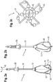
- Fig. 1a shows in a side view
- Fig. 1b in a perspective view 1b
- Fig. 1c in a plan view of a first embodiment of a stirring device according to the present invention for an electric or electromotive kitchen appliance, in particular a hand mixer (not shown).
- the illustrated stirring device is designed as a whorl 1, which is driven in rotation by an electric motor of the kitchen appliance.
- the stirring device 1 a coupling 20 which is arranged at the upper end of a drive shaft 10.
- the clutch 20 cooperates with another clutch which is arranged in the kitchen appliance, so that the electric motor can drive the stirring device 1.
- the clutch system thus drives the drive shaft 10 in rotation.
- the drive shaft 10 is made of a metallic material, in particular stainless steel, which ensures high rigidity and ease of manufacture.
- the entire stirring device 1 together with the drive shaft 10 is integrally made of plastic or other suitable material.
- the drive shaft 10 has at its end opposite the coupling 20 a first and a second loop-shaped bracket 11 and 15.
- the bracket 11, 15 may have in their length at least partially a constant cross-section.
- the brackets 11 and 15 may consist of a metallic material and are formed wire-shaped. By choosing the material can be ensured that the bracket 11, 15 are substantially rigid.
- the material, in particular wire-shaped material, is preferably selected so that no significant deformations of the stirring device 1 occur during operation.
- the end 12 of the drive shaft 10 is also rigidly and securely connected to the brackets 11 and 15. The connection in the region of the end 12 of the drive shaft 10 may have different configurations.
- brackets 11 and 15 are made in one piece with the drive shaft 10, but a fixed coupling or a soldering or welding point is also feasible.
- connection should be such that in operation, the stirrups 11 and 15 are fixedly connected to the end 12 of the drive shaft 10 to act on the food or the food accordingly.
- the brackets 11 and 15 are wire-shaped according to an exemplary embodiment and are made of a metallic wire.
- the brackets 11 and 15 emerge from the end 12 of the drive shaft 10 and span substantially two surfaces, which preferably meet at right angles to each other.
- the two brackets 11 and 15 on a cross point 21, in which they can be soldered together, for example.
- the two brackets have no contact point 21, so that the soldering process is omitted during manufacture.
- the two wire-shaped brackets 11 and 15 can be hooked or wound into each other at the contact point 21.
- the stirring device it is likewise conceivable for the stirring device to have further stirrups 11, 15 which project symmetrically out of the end 12 of the drive shaft 10 and define a plurality or a multiplicity of planes crossing each other.
- the wire-shaped metallic shackles 11, 15 have in the lower area, i. in their respective effective area 16, 17, several active bodies 13.
- the active bodies 13 may (as shown) be spherical and either also made of a metallic material or plastic. Other materials are conceivable. Also possible is the one-piece design of the active body 13 together with the brackets 11 and 15. In this case, these could be produced for example by means of a casting process in a manufacturing step. Also, a soldering of the spherical active body 13 to the brackets 11 and 15 in a separate manufacturing step can be implemented or realized.
- the active bodies 13 are arranged in the lower third, corresponding to the first and second active regions 17, 18, the yokes 11 and 15.
- This lower third is also the area that is essentially in permanent contact with the food (ie food).
- the effective range 14 can be improved on the food ie increased.
- the impact of the stirring device 1 can be improved, since with the help of the active body 13 better air can be taken or incorporated into the food. For example, with this stirrer egg whites are beaten much faster than with conventional Stirrers.
- the brackets 11 and 15 are made stiff from a wire-shaped metallic material, so that their shape during rotation during operation of the hand mixer remains substantially unchanged. Thus, effectively all the torque of the electric motor is transferred to the food without the stirrups 11 and 15 experiencing elastic deformation caused by centrifugal forces.
- the effective area 14 is thus advantageously increased.
- the effective area 14 of the respective active bodies 13 can also act on the food, which improves the quality and processing speed.
- the stirrups 11 and 15 each have a pair of oblique portions or inclined portions 18 and 19 which act like a screw in the rotation of the stirrer 1.
- the brackets preferably wire brackets 11 and 14, substantially form a rectangular shape, and the inclined portions (or portions) 18, 19 are oppositely inclined with respect to the axis R of the stirring device 1.
- the axis R is defined by the drive shaft 10.
- the two brackets 11 and 15 intersect in a lying on the axis of rotation R point 21 and are connected to each other, for example, by a solder joint.
- the active bodies 13 are arranged at different levels in the lower region of the brackets 11 and 15, so that during operation the foodstuff is effectively processed by the active surfaces 14 during the machining process.
- the active bodies 13 of the first wire-shaped bracket are arranged substantially in a horizontal section of the rectangular bracket 11. The horizontal portion corresponds to the portion which is defined substantially parallel to a bowl bottom during operation of the stirring device 1.
- the active body 13 according to the invention can be arranged on the second bracket 15 in a vertical section which is perpendicular to the bottom of the dish.
- the vertical portions may further have an inclined angle to the bottom of the bowl.
- the active body 13 of the second bracket 13th are arranged in the vertical or inclined region, they experience a faster rotational speed, since the radius is increased to the rotation axis R. Consequently, the effective area 14 of these active bodies 13 can be used at an increased processing speed.
- the stirring device 1 can be used for example in a hand mixer, but tools of a food processor can also be provided with the active body 13 according to the invention.
- the active bodies 13 are soldered to the metallic wire brackets 11, 15.
- they may have suitable holes through which the wire hangers 11, 15 are passed accordingly, in order subsequently to be soldered to them or connected in another method.
- the wire straps 11, 15 have a different cross-section, for example an elliptical or quadrangular or the like, the active bodies 13 can be better fixed during assembly.
- the bore of the active body 13 usually has a round cross-section, so that, for example, an elliptical or quadrangular cross-section of the wire bracket 11 or 15 can cooperate with the round bore and the active body can thus be prefixed to be subsequently soldered can. This facilitates assembly, since the active body 13 on the wire hanger can not slide back and forth uncontrolled. Similar results can be achieved with other cross-sectional profiles.
- Fig. 2a, 2b, 2c show three further views of a stirring device according to a second embodiment of the present invention.
- the two brackets 11 and 15 each have four active bodies 13 in order to increase the effective area 14 to the food to be processed.
- the basic shape of the bracket 11 and 15 corresponds to the shape which in the Fig. 1a, 1b, 1c is described in more detail.
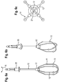
- the Fig. 3a, 3b and 3c show a third embodiment of the present invention, in which the active bodies are cylindrically shaped and similar as in the Fig. 1a, 1b and 1c are arranged in pairs on the respective brackets 11 and 15 respectively.
- the cylindrical shape of the active body 13 has an enlarged active surface 14 on the food, so that better results can be achieved.
- the brackets 11 and 15 are also in accordance with this third embodiment, wire-shaped and the active body 13 enlarge sections of the temple cross-section and that in the area where they are arranged. A similar effect can be achieved with spherical active body 13, as in the Fig. 1 and 2 is described in more detail.
- Fig. 4a, 4b and 4c show a further embodiment in which, as disclosed in the third embodiment, cylindrical active body 13 are used.
- cylindrical active body 13 In order to increase the effective area 14, in each case four active bodies 13 for the respective bracket 11 or 15 are used.
- Fig. 5a, 5b and 5c show a possible fifth embodiment of a stirring device according to the present invention.
- the bracket 11 and 15 have no oblique sections 18 and 19 and to increase the effective area 14 are here also spherical active body in pairs on the brackets 11 and 15 respectively.
- Fig. 6a, 6b and 6c show a further embodiment of the stirring device, in which four spherical active body 13 per bracket 11 and 15 are used.
- Fig. 7a, 7b and 7c or 8a, 8b and 8c correspond to the above-mentioned fifth embodiment, wherein in turn to increase the effective area 14 cylindrical active body 13 are used.
- the active body according to the invention By using the active body according to the invention on a stirrup of the stirring device effectively the active surface can be increased to a food, especially food, so that when using the stirring device in a hand mixer, blender, blender or a food processor, the processing time can be shortened advantageous.
Landscapes
- Engineering & Computer Science (AREA)
- Mechanical Engineering (AREA)
- Food Science & Technology (AREA)
- Food-Manufacturing Devices (AREA)
- Mixers Of The Rotary Stirring Type (AREA)
Claims (11)
- Ustensile de cuisine, en particulier robot ménager, mixer manuel ou plongeur, avec au moins un dispositif de brassage (1), en particulier batteur, pour le traitement de denrées, le dispositif de brassage (1) comprenant un arbre d'entraînement (10), sur une extrémité duquel sont agencés un point de couplage (20) pour le couplage avec un ustensile de cuisine et sur l'autre extrémité (12) duquel se trouve agencée une pluralité, en particulier deux surfaces utiles (14) en étrier (11, 15) à boucle, au moins deux corps utiles (13) étant disposés chacun sur les étriers (11, 15), lesquels augmentent la surface utile (14) sur la denrée à traiter, le corps utile (13) respectif présentant des mesures de hauteur, largeur et longueur maximale dans un rapport de 1:1:2, en particulier dans un rapport de 1:1:1,5, de préférence dans un rapport de 1:1:1, caractérisée en ce que les corps utiles (13) des étriers (11, 15) sont agencés chacun sur des niveaux différents symétriquement à l'axe de rotation de l'arbre d'entraînement (10) sur l'étrier (11, 15) respectif et restent ensuite en contact sur différents niveaux avec la denrée.
- Ustensile de cuisine selon la revendication 1, caractérisé en ce que les corps utiles (13) sont exécutés sur l'étrier (11, 15) sous forme de billes, de cylindres, de cubes, de pyramides, de dés ou de tétraèdres.
- Ustensile de cuisine selon l'une des revendications précédentes, caractérisé en ce que les étriers (11, 15) sont exécutés filaires.
- Ustensile de cuisine selon l'une des revendications précédentes, caractérisé en ce que les étriers (11, 15) sont exécutés raides.
- Ustensile de cuisine selon l'une des revendications précédentes, caractérisé en ce que les étriers (11, 15) présentent une coupe circulaire, carrée, rectangle, plate ou une autrement profilée.
- Ustensile de cuisine selon l'une des revendications précédentes, caractérisé en ce que les étriers (11, 15) sont fabriqués en matière métallique, en particulier en acier ou en matière synthétique.
- Ustensile de cuisine selon l'une des revendications précédentes, caractérisé en ce que les corps utiles (13) sont fabriqués en matière métallique, en particulier en acier ou en matière synthétique.
- Ustensile de cuisine selon l'une des revendications précédentes, caractérisé en ce que la surface des corps utiles (13) sont exécutées planes ou ondulées.
- Ustensile de cuisine selon l'une des revendications précédentes, caractérisé en ce que les corps utiles (13) sont exécutées amovibles et/ou remplaçables.
- Ustensile de cuisine (1) selon la revendication 10, caractérisé en ce que les étriers (11, 15) présentent un point d'intersection (21) commun situé sur l'axe de rotation (R) de l'arbre d'entraînement (10).
- Ustensile de cuisine (1) selon l'une des revendications précédentes, caractérisé en ce que les étriers (11, 15) présentent chacun quatre corps utiles (13).
Priority Applications (2)
| Application Number | Priority Date | Filing Date | Title |
|---|---|---|---|
| PL10779763T PL2509480T3 (pl) | 2009-12-09 | 2010-11-11 | Urządzenie kuchenne z urządzeniem mieszającym |
| SI201031841T SI2509480T1 (sl) | 2009-12-09 | 2010-11-11 | Kuhinjski aparat z mešalno napravo |
Applications Claiming Priority (2)
| Application Number | Priority Date | Filing Date | Title |
|---|---|---|---|
| DE102009057448A DE102009057448A1 (de) | 2009-12-09 | 2009-12-09 | Küchengerät mit Rührvorrichtung |
| PCT/EP2010/067270 WO2011069768A1 (fr) | 2009-12-09 | 2010-11-11 | Appareil de cuisine avec dispositif mélangeur |
Publications (2)
| Publication Number | Publication Date |
|---|---|
| EP2509480A1 EP2509480A1 (fr) | 2012-10-17 |
| EP2509480B1 true EP2509480B1 (fr) | 2019-01-09 |
Family
ID=43499981
Family Applications (1)
| Application Number | Title | Priority Date | Filing Date |
|---|---|---|---|
| EP10779763.1A Active EP2509480B1 (fr) | 2009-12-09 | 2010-11-11 | Appareil de cuisine avec dispositif mélangeur |
Country Status (7)
| Country | Link |
|---|---|
| EP (1) | EP2509480B1 (fr) |
| DE (1) | DE102009057448A1 (fr) |
| ES (1) | ES2709513T3 (fr) |
| PL (1) | PL2509480T3 (fr) |
| RU (1) | RU2532158C2 (fr) |
| SI (1) | SI2509480T1 (fr) |
| WO (1) | WO2011069768A1 (fr) |
Families Citing this family (2)
| Publication number | Priority date | Publication date | Assignee | Title |
|---|---|---|---|---|
| JP5857157B2 (ja) | 2012-07-12 | 2016-02-10 | コーニンクレッカ フィリップス エヌ ヴェKoninklijke Philips N.V. | 液体食料品を攪拌するための装置 |
| US11641979B2 (en) * | 2020-11-12 | 2023-05-09 | DanDre Technology Innovation Limited | Culinary whisk |
Family Cites Families (10)
| Publication number | Priority date | Publication date | Assignee | Title |
|---|---|---|---|---|
| CH170402A (de) * | 1933-04-24 | 1934-07-15 | Gustav Ammann Emil | Gerät zum Rühren bezw. Schlagen von Rahm, Eiern, Saucen und dergleichen. |
| GB397448A (en) * | 1933-07-13 | 1933-08-24 | William James Mahony | Improvements in or relating to beaters for food stuffs and the like |
| DE1429978A1 (de) | 1961-10-10 | 1968-11-14 | Krups Fa Robert | Quirl |
| DE1206129B (de) * | 1963-04-27 | 1965-12-02 | Electrostar G M B H | Passiergeraet bzw. Passierpilz zur Antriebsverbindung mit einer elektromotorisch angetriebenen, von Hand tragbaren Kuechenmaschine |
| DE3225450C2 (de) * | 1982-07-07 | 1985-03-14 | Siemens AG, 1000 Berlin und 8000 München | Rührbesen |
| JPS63178568U (fr) * | 1987-05-09 | 1988-11-18 | ||
| AT392581B (de) | 1989-07-27 | 1991-04-25 | Philips Nv | Quirl fuer eine kuechenmaschine |
| DE19733331C2 (de) * | 1997-08-01 | 2001-09-13 | Wmf Wuerttemberg Metallwaren | Schneebesen |
| JP2005034558A (ja) * | 2003-07-14 | 2005-02-10 | Takashi Taji | 米とぎ器 |
| US20060050606A1 (en) * | 2004-09-08 | 2006-03-09 | Thomas Overthun | Methods and apparatus for a whisk |
-
2009
- 2009-12-09 DE DE102009057448A patent/DE102009057448A1/de not_active Ceased
-
2010
- 2010-11-11 ES ES10779763T patent/ES2709513T3/es active Active
- 2010-11-11 RU RU2012123870/12A patent/RU2532158C2/ru active
- 2010-11-11 WO PCT/EP2010/067270 patent/WO2011069768A1/fr not_active Ceased
- 2010-11-11 SI SI201031841T patent/SI2509480T1/sl unknown
- 2010-11-11 PL PL10779763T patent/PL2509480T3/pl unknown
- 2010-11-11 EP EP10779763.1A patent/EP2509480B1/fr active Active
Non-Patent Citations (1)
| Title |
|---|
| None * |
Also Published As
| Publication number | Publication date |
|---|---|
| PL2509480T3 (pl) | 2019-06-28 |
| RU2012123870A (ru) | 2014-01-20 |
| EP2509480A1 (fr) | 2012-10-17 |
| SI2509480T1 (sl) | 2019-02-28 |
| DE102009057448A1 (de) | 2011-06-16 |
| WO2011069768A1 (fr) | 2011-06-16 |
| RU2532158C2 (ru) | 2014-10-27 |
| ES2709513T3 (es) | 2019-04-16 |
Similar Documents
| Publication | Publication Date | Title |
|---|---|---|
| EP3578089B1 (fr) | Dispositif de nettoyage pour un bac à agitation d'un robot de cuisine entraîné par un moteur électrique | |
| DE60210130T2 (de) | Mischvorrichtung für eine speiseeismaschine insbesondere für hausgebrauch | |
| EP3250098B1 (fr) | Bol mixeur pour robot ménager | |
| EP2488288B1 (fr) | Dispositif mélangeur pour un appareil électroménager de préparation culinaire | |
| DE202009011685U1 (de) | Vorrichtung zur Verarbeitung von Lebensmitteln | |
| DE102008029369B4 (de) | Küchenmaschine, Werkzeuganordnung und Verfahren, insbesondere zum Kneten von Teig | |
| DE69810495T2 (de) | Zusatzgerät für die herstellung von emulsionen, schäumen und dispersionen und küchenmaschine dafür | |
| EP3051989A1 (fr) | Procédé de montage d'un outil pour ustensile de cuisine | |
| EP2509480B1 (fr) | Appareil de cuisine avec dispositif mélangeur | |
| EP2269491A1 (fr) | Outil de malaxage pour pâtes lourdes | |
| DE3610740C2 (fr) | ||
| DE60222025T2 (de) | Umhülltes küchengerät und umhüllung für ein küchengerät | |
| EP3469969B1 (fr) | Robot de cuisine entraîné par moteur électrique ainsi que bac à agitation et agitateur associés | |
| EP0410527B1 (fr) | Fouet pour un robot de cuisine | |
| DE1554642A1 (de) | Mehrarmiges Ruehr- und Knetwerkzeug fuer die Ruehrschuessel einer elektrisch angetriebenen Haushalt-Kuechenmaschine | |
| WO2008049247A1 (fr) | Mousseur à lait électrique | |
| DE202009009041U1 (de) | Drehmomentgünstiges Rührwerkzeug | |
| EP1103211A1 (fr) | Appareil de cuisine pour agiter, mousser et détacher | |
| DE102017221138B4 (de) | Rührgefäß für einen Stabmixer, Einsatzelement für ein Rührgefäß und Küchenrührvorrichtung | |
| EP3488744B1 (fr) | Élément de mixeur plongeur, partie d'agrandissement pour un élément de mixeur plongeur et mixeur plongeur de taille variable | |
| DE19733331C2 (de) | Schneebesen | |
| DE318289C (fr) | ||
| CH705441A2 (de) | Küchenschneebesen. | |
| EP2269494A1 (fr) | Elément de tête pour un outil de malaxage | |
| DE202022002539U1 (de) | Vorrichtung zum Mischen |
Legal Events
| Date | Code | Title | Description |
|---|---|---|---|
| PUAI | Public reference made under article 153(3) epc to a published international application that has entered the european phase |
Free format text: ORIGINAL CODE: 0009012 |
|
| 17P | Request for examination filed |
Effective date: 20120709 |
|
| AK | Designated contracting states |
Kind code of ref document: A1 Designated state(s): AL AT BE BG CH CY CZ DE DK EE ES FI FR GB GR HR HU IE IS IT LI LT LU LV MC MK MT NL NO PL PT RO RS SE SI SK SM TR |
|
| DAX | Request for extension of the european patent (deleted) | ||
| RAP1 | Party data changed (applicant data changed or rights of an application transferred) |
Owner name: BSH HAUSGERAETE GMBH |
|
| STAA | Information on the status of an ep patent application or granted ep patent |
Free format text: STATUS: EXAMINATION IS IN PROGRESS |
|
| 17Q | First examination report despatched |
Effective date: 20180202 |
|
| GRAP | Despatch of communication of intention to grant a patent |
Free format text: ORIGINAL CODE: EPIDOSNIGR1 |
|
| STAA | Information on the status of an ep patent application or granted ep patent |
Free format text: STATUS: GRANT OF PATENT IS INTENDED |
|
| INTG | Intention to grant announced |
Effective date: 20180731 |
|
| GRAS | Grant fee paid |
Free format text: ORIGINAL CODE: EPIDOSNIGR3 |
|
| GRAA | (expected) grant |
Free format text: ORIGINAL CODE: 0009210 |
|
| STAA | Information on the status of an ep patent application or granted ep patent |
Free format text: STATUS: THE PATENT HAS BEEN GRANTED |
|
| AK | Designated contracting states |
Kind code of ref document: B1 Designated state(s): AL AT BE BG CH CY CZ DE DK EE ES FI FR GB GR HR HU IE IS IT LI LT LU LV MC MK MT NL NO PL PT RO RS SE SI SK SM TR |
|
| REG | Reference to a national code |
Ref country code: GB Ref legal event code: FG4D Free format text: NOT ENGLISH |
|
| REG | Reference to a national code |
Ref country code: CH Ref legal event code: EP Ref country code: AT Ref legal event code: REF Ref document number: 1086284 Country of ref document: AT Kind code of ref document: T Effective date: 20190115 |
|
| REG | Reference to a national code |
Ref country code: DE Ref legal event code: R096 Ref document number: 502010015719 Country of ref document: DE |
|
| REG | Reference to a national code |
Ref country code: IE Ref legal event code: FG4D Free format text: LANGUAGE OF EP DOCUMENT: GERMAN |
|
| REG | Reference to a national code |
Ref country code: ES Ref legal event code: FG2A Ref document number: 2709513 Country of ref document: ES Kind code of ref document: T3 Effective date: 20190416 |
|
| REG | Reference to a national code |
Ref country code: NL Ref legal event code: MP Effective date: 20190109 |
|
| REG | Reference to a national code |
Ref country code: LT Ref legal event code: MG4D |
|
| PG25 | Lapsed in a contracting state [announced via postgrant information from national office to epo] |
Ref country code: NL Free format text: LAPSE BECAUSE OF FAILURE TO SUBMIT A TRANSLATION OF THE DESCRIPTION OR TO PAY THE FEE WITHIN THE PRESCRIBED TIME-LIMIT Effective date: 20190109 |
|
| PG25 | Lapsed in a contracting state [announced via postgrant information from national office to epo] |
Ref country code: LT Free format text: LAPSE BECAUSE OF FAILURE TO SUBMIT A TRANSLATION OF THE DESCRIPTION OR TO PAY THE FEE WITHIN THE PRESCRIBED TIME-LIMIT Effective date: 20190109 Ref country code: FI Free format text: LAPSE BECAUSE OF FAILURE TO SUBMIT A TRANSLATION OF THE DESCRIPTION OR TO PAY THE FEE WITHIN THE PRESCRIBED TIME-LIMIT Effective date: 20190109 Ref country code: NO Free format text: LAPSE BECAUSE OF FAILURE TO SUBMIT A TRANSLATION OF THE DESCRIPTION OR TO PAY THE FEE WITHIN THE PRESCRIBED TIME-LIMIT Effective date: 20190409 Ref country code: PT Free format text: LAPSE BECAUSE OF FAILURE TO SUBMIT A TRANSLATION OF THE DESCRIPTION OR TO PAY THE FEE WITHIN THE PRESCRIBED TIME-LIMIT Effective date: 20190509 Ref country code: SE Free format text: LAPSE BECAUSE OF FAILURE TO SUBMIT A TRANSLATION OF THE DESCRIPTION OR TO PAY THE FEE WITHIN THE PRESCRIBED TIME-LIMIT Effective date: 20190109 |
|
| PG25 | Lapsed in a contracting state [announced via postgrant information from national office to epo] |
Ref country code: HR Free format text: LAPSE BECAUSE OF FAILURE TO SUBMIT A TRANSLATION OF THE DESCRIPTION OR TO PAY THE FEE WITHIN THE PRESCRIBED TIME-LIMIT Effective date: 20190109 Ref country code: BG Free format text: LAPSE BECAUSE OF FAILURE TO SUBMIT A TRANSLATION OF THE DESCRIPTION OR TO PAY THE FEE WITHIN THE PRESCRIBED TIME-LIMIT Effective date: 20190409 Ref country code: RS Free format text: LAPSE BECAUSE OF FAILURE TO SUBMIT A TRANSLATION OF THE DESCRIPTION OR TO PAY THE FEE WITHIN THE PRESCRIBED TIME-LIMIT Effective date: 20190109 Ref country code: LV Free format text: LAPSE BECAUSE OF FAILURE TO SUBMIT A TRANSLATION OF THE DESCRIPTION OR TO PAY THE FEE WITHIN THE PRESCRIBED TIME-LIMIT Effective date: 20190109 Ref country code: IS Free format text: LAPSE BECAUSE OF FAILURE TO SUBMIT A TRANSLATION OF THE DESCRIPTION OR TO PAY THE FEE WITHIN THE PRESCRIBED TIME-LIMIT Effective date: 20190509 Ref country code: GR Free format text: LAPSE BECAUSE OF FAILURE TO SUBMIT A TRANSLATION OF THE DESCRIPTION OR TO PAY THE FEE WITHIN THE PRESCRIBED TIME-LIMIT Effective date: 20190410 |
|
| REG | Reference to a national code |
Ref country code: DE Ref legal event code: R097 Ref document number: 502010015719 Country of ref document: DE |
|
| PG25 | Lapsed in a contracting state [announced via postgrant information from national office to epo] |
Ref country code: SK Free format text: LAPSE BECAUSE OF FAILURE TO SUBMIT A TRANSLATION OF THE DESCRIPTION OR TO PAY THE FEE WITHIN THE PRESCRIBED TIME-LIMIT Effective date: 20190109 Ref country code: EE Free format text: LAPSE BECAUSE OF FAILURE TO SUBMIT A TRANSLATION OF THE DESCRIPTION OR TO PAY THE FEE WITHIN THE PRESCRIBED TIME-LIMIT Effective date: 20190109 Ref country code: CZ Free format text: LAPSE BECAUSE OF FAILURE TO SUBMIT A TRANSLATION OF THE DESCRIPTION OR TO PAY THE FEE WITHIN THE PRESCRIBED TIME-LIMIT Effective date: 20190109 Ref country code: RO Free format text: LAPSE BECAUSE OF FAILURE TO SUBMIT A TRANSLATION OF THE DESCRIPTION OR TO PAY THE FEE WITHIN THE PRESCRIBED TIME-LIMIT Effective date: 20190109 Ref country code: AL Free format text: LAPSE BECAUSE OF FAILURE TO SUBMIT A TRANSLATION OF THE DESCRIPTION OR TO PAY THE FEE WITHIN THE PRESCRIBED TIME-LIMIT Effective date: 20190109 Ref country code: DK Free format text: LAPSE BECAUSE OF FAILURE TO SUBMIT A TRANSLATION OF THE DESCRIPTION OR TO PAY THE FEE WITHIN THE PRESCRIBED TIME-LIMIT Effective date: 20190109 Ref country code: IT Free format text: LAPSE BECAUSE OF FAILURE TO SUBMIT A TRANSLATION OF THE DESCRIPTION OR TO PAY THE FEE WITHIN THE PRESCRIBED TIME-LIMIT Effective date: 20190109 |
|
| PLBE | No opposition filed within time limit |
Free format text: ORIGINAL CODE: 0009261 |
|
| STAA | Information on the status of an ep patent application or granted ep patent |
Free format text: STATUS: NO OPPOSITION FILED WITHIN TIME LIMIT |
|
| PG25 | Lapsed in a contracting state [announced via postgrant information from national office to epo] |
Ref country code: SM Free format text: LAPSE BECAUSE OF FAILURE TO SUBMIT A TRANSLATION OF THE DESCRIPTION OR TO PAY THE FEE WITHIN THE PRESCRIBED TIME-LIMIT Effective date: 20190109 |
|
| 26N | No opposition filed |
Effective date: 20191010 |
|
| PG25 | Lapsed in a contracting state [announced via postgrant information from national office to epo] |
Ref country code: TR Free format text: LAPSE BECAUSE OF FAILURE TO SUBMIT A TRANSLATION OF THE DESCRIPTION OR TO PAY THE FEE WITHIN THE PRESCRIBED TIME-LIMIT Effective date: 20190109 |
|
| REG | Reference to a national code |
Ref country code: CH Ref legal event code: PL |
|
| PG25 | Lapsed in a contracting state [announced via postgrant information from national office to epo] |
Ref country code: MC Free format text: LAPSE BECAUSE OF FAILURE TO SUBMIT A TRANSLATION OF THE DESCRIPTION OR TO PAY THE FEE WITHIN THE PRESCRIBED TIME-LIMIT Effective date: 20190109 Ref country code: LI Free format text: LAPSE BECAUSE OF NON-PAYMENT OF DUE FEES Effective date: 20191130 Ref country code: CH Free format text: LAPSE BECAUSE OF NON-PAYMENT OF DUE FEES Effective date: 20191130 Ref country code: LU Free format text: LAPSE BECAUSE OF NON-PAYMENT OF DUE FEES Effective date: 20191111 |
|
| REG | Reference to a national code |
Ref country code: BE Ref legal event code: MM Effective date: 20191130 |
|
| GBPC | Gb: european patent ceased through non-payment of renewal fee |
Effective date: 20191111 |
|
| PG25 | Lapsed in a contracting state [announced via postgrant information from national office to epo] |
Ref country code: IE Free format text: LAPSE BECAUSE OF NON-PAYMENT OF DUE FEES Effective date: 20191111 Ref country code: GB Free format text: LAPSE BECAUSE OF NON-PAYMENT OF DUE FEES Effective date: 20191111 |
|
| PG25 | Lapsed in a contracting state [announced via postgrant information from national office to epo] |
Ref country code: BE Free format text: LAPSE BECAUSE OF NON-PAYMENT OF DUE FEES Effective date: 20191130 |
|
| PG25 | Lapsed in a contracting state [announced via postgrant information from national office to epo] |
Ref country code: CY Free format text: LAPSE BECAUSE OF FAILURE TO SUBMIT A TRANSLATION OF THE DESCRIPTION OR TO PAY THE FEE WITHIN THE PRESCRIBED TIME-LIMIT Effective date: 20190109 |
|
| PG25 | Lapsed in a contracting state [announced via postgrant information from national office to epo] |
Ref country code: MT Free format text: LAPSE BECAUSE OF FAILURE TO SUBMIT A TRANSLATION OF THE DESCRIPTION OR TO PAY THE FEE WITHIN THE PRESCRIBED TIME-LIMIT Effective date: 20190109 Ref country code: HU Free format text: LAPSE BECAUSE OF FAILURE TO SUBMIT A TRANSLATION OF THE DESCRIPTION OR TO PAY THE FEE WITHIN THE PRESCRIBED TIME-LIMIT; INVALID AB INITIO Effective date: 20101111 |
|
| PG25 | Lapsed in a contracting state [announced via postgrant information from national office to epo] |
Ref country code: MK Free format text: LAPSE BECAUSE OF FAILURE TO SUBMIT A TRANSLATION OF THE DESCRIPTION OR TO PAY THE FEE WITHIN THE PRESCRIBED TIME-LIMIT Effective date: 20190109 |
|
| PGFP | Annual fee paid to national office [announced via postgrant information from national office to epo] |
Ref country code: FR Payment date: 20221118 Year of fee payment: 13 Ref country code: ES Payment date: 20221216 Year of fee payment: 13 Ref country code: AT Payment date: 20221117 Year of fee payment: 13 |
|
| PGFP | Annual fee paid to national office [announced via postgrant information from national office to epo] |
Ref country code: SI Payment date: 20221102 Year of fee payment: 13 |
|
| REG | Reference to a national code |
Ref country code: AT Ref legal event code: MM01 Ref document number: 1086284 Country of ref document: AT Kind code of ref document: T Effective date: 20231111 |
|
| PG25 | Lapsed in a contracting state [announced via postgrant information from national office to epo] |
Ref country code: AT Free format text: LAPSE BECAUSE OF NON-PAYMENT OF DUE FEES Effective date: 20231111 |
|
| PG25 | Lapsed in a contracting state [announced via postgrant information from national office to epo] |
Ref country code: AT Free format text: LAPSE BECAUSE OF NON-PAYMENT OF DUE FEES Effective date: 20231111 Ref country code: SI Free format text: LAPSE BECAUSE OF NON-PAYMENT OF DUE FEES Effective date: 20231112 |
|
| REG | Reference to a national code |
Ref country code: SI Ref legal event code: KO00 Effective date: 20240813 |
|
| PG25 | Lapsed in a contracting state [announced via postgrant information from national office to epo] |
Ref country code: FR Free format text: LAPSE BECAUSE OF NON-PAYMENT OF DUE FEES Effective date: 20231130 |
|
| PG25 | Lapsed in a contracting state [announced via postgrant information from national office to epo] |
Ref country code: FR Free format text: LAPSE BECAUSE OF NON-PAYMENT OF DUE FEES Effective date: 20231130 |
|
| REG | Reference to a national code |
Ref country code: ES Ref legal event code: FD2A Effective date: 20250102 |
|
| PG25 | Lapsed in a contracting state [announced via postgrant information from national office to epo] |
Ref country code: ES Free format text: LAPSE BECAUSE OF NON-PAYMENT OF DUE FEES Effective date: 20231112 |
|
| PG25 | Lapsed in a contracting state [announced via postgrant information from national office to epo] |
Ref country code: ES Free format text: LAPSE BECAUSE OF NON-PAYMENT OF DUE FEES Effective date: 20231112 |
|
| PGFP | Annual fee paid to national office [announced via postgrant information from national office to epo] |
Ref country code: DE Payment date: 20251130 Year of fee payment: 16 |
|
| PGFP | Annual fee paid to national office [announced via postgrant information from national office to epo] |
Ref country code: PL Payment date: 20251107 Year of fee payment: 16 |