EP2511203A1 - Procédé et dispositif de transport de récipients ou de paquets de récipients - Google Patents
Procédé et dispositif de transport de récipients ou de paquets de récipients Download PDFInfo
- Publication number
- EP2511203A1 EP2511203A1 EP12162836A EP12162836A EP2511203A1 EP 2511203 A1 EP2511203 A1 EP 2511203A1 EP 12162836 A EP12162836 A EP 12162836A EP 12162836 A EP12162836 A EP 12162836A EP 2511203 A1 EP2511203 A1 EP 2511203A1
- Authority
- EP
- European Patent Office
- Prior art keywords
- containers
- conveying
- conveying elements
- elements
- container groups
- Prior art date
- Legal status (The legal status is an assumption and is not a legal conclusion. Google has not performed a legal analysis and makes no representation as to the accuracy of the status listed.)
- Granted
Links
Images

Classifications
-
- B—PERFORMING OPERATIONS; TRANSPORTING
- B65—CONVEYING; PACKING; STORING; HANDLING THIN OR FILAMENTARY MATERIAL
- B65G—TRANSPORT OR STORAGE DEVICES, e.g. CONVEYORS FOR LOADING OR TIPPING, SHOP CONVEYOR SYSTEMS OR PNEUMATIC TUBE CONVEYORS
- B65G54/00—Non-mechanical conveyors not otherwise provided for
- B65G54/02—Non-mechanical conveyors not otherwise provided for electrostatic, electric, or magnetic
-
- B—PERFORMING OPERATIONS; TRANSPORTING
- B65—CONVEYING; PACKING; STORING; HANDLING THIN OR FILAMENTARY MATERIAL
- B65G—TRANSPORT OR STORAGE DEVICES, e.g. CONVEYORS FOR LOADING OR TIPPING, SHOP CONVEYOR SYSTEMS OR PNEUMATIC TUBE CONVEYORS
- B65G47/00—Article or material-handling devices associated with conveyors; Methods employing such devices
- B65G47/22—Devices influencing the relative position or the attitude of articles during transit by conveyors
- B65G47/26—Devices influencing the relative position or the attitude of articles during transit by conveyors arranging the articles, e.g. varying spacing between individual articles
- B65G47/28—Devices influencing the relative position or the attitude of articles during transit by conveyors arranging the articles, e.g. varying spacing between individual articles during transit by a single conveyor
Definitions
- the present invention relates to a method and a device for transporting containers or container bundles.
- Such transport devices and transport methods have long been known from the prior art. These serve, for example, to transport containers or groups of containers from one treatment device, such as a filling device, to another treatment device, such as a labeling machine or a capper. Usually, the containers or the groups of containers are occasionally transported.
- these containers or groups of containers have predetermined distances.
- different treatment units work with different container distances or a division between the containers must be changed.
- devices are known from the prior art, which change a pitch of the containers. Examples of this are Einteilschnecken call, to which the containers are supplied without clearance and which then change these distances between the containers.
- the disadvantage of these Einteilschnecken is that these containers must be supplied without gaps and in turn pass the containers with a well-defined distance.
- it may be partially desirable to arbitrarily set these distances between the containers for example, from any distance to another arbitrary distance.
- the present invention is therefore based on the object to provide transport devices with which distances between the items to be conveyed are adjustable. Furthermore, it should also be possible that the containers or groups of containers can be supplied at different intervals.
- a plurality of containers and / or container groups are conveyed along a predetermined transport path and with a predetermined distance between the containers and / or container groups to a conveyor unit and the conveyor unit transports the containers and / or Container groups with at least two first conveying elements for conveying the containers and / or container groups, wherein these conveying elements each move along a first predetermined movement path on a circumferentially formed carrier and wherein these conveying elements contact the containers and / or container groups each with a Maisier endeavor and so a distance between containers or container groups.
- a container group is understood to mean in particular a combination of several containers (in particular a container), in which the individual containers are advantageously arranged in a predetermined position relative to one another.
- the conveying elements are driven by means of a drive device designed as a linear motor, wherein the drive device is in operative connection with magnets of the conveying elements and a control device allows independent movement of the first conveying elements, so that the distance between two conveyed containers or container groups is changeable or changed.
- the containers are at least temporarily supported during transport with the conveying elements by means of a support means.
- a support means it is possible that the containers or container groups are conveyed by means of a conveyor belt and then a distance between the containers is changed.
- the containers are guided, for example, with gripping elements which support the supporting rings of the containers.
- the containers are guided during their transport with the conveying elements in a direction parallel to the transport path direction. In this way it is prevented that the containers can deviate laterally from the transport path during their transport. So it is conceivable, for example, that lateral guide rails are provided, which hold the containers substantially on their transport path.
- the conveying elements themselves to be adapted such that the containers or groups of containers (or containers) can not deviate laterally from the transport path.
- the conveying elements may for example have curved sections or recesses, which each serve to receive the containers or container groups.
- the conveying elements themselves can cause the containers can not deviate laterally from their transport path, such as by the conveyor elements contact the containers or groups of containers from two different sides, which are opposite each other.
- the containers are transported with the conveyor unit into a filling or labeling device which fills or labels the containers.
- the transport elements are at least temporarily moved against the transport direction of the containers or container groups.
- This movement advantageously serves to return the conveying elements relative to their carrier.
- a movement speed of the conveying elements against the transport path of the containers is at least temporarily higher than a transport speed of the conveying elements along or in the direction of the transport path.
- an average speed of the conveying elements against the transport path or the transport direction of the containers is higher than an average speed of the conveying elements in the transport direction of the containers or container groups.
- the containers or container groups are contacted during their transport with the conveyor unit to at least three spaced-apart areas of the container, for example at a bottom portion and at two wall portions. There is thus advantageously no overlap between these areas.
- the containers are changed during their transport with the first conveying elements by a lateral engagement with regard to their (transport) speed.
- the conveying elements can, for example, be frictionally in contact with corresponding side walls of the containers
- the present invention is further directed to a device for transporting containers or container groups, which has a first conveyor unit, which transports the containers along a predetermined transport path.
- the conveyor unit comprises a support means for supporting the containers or the container group during transport and at least two first conveyor elements for conveying the containers, said conveyor elements are each arranged along a first predetermined movement path movable on a circumferentially formed carrier and wherein These conveying elements each have a Maisier Sciences for contacting the containers and at least one magnet and in particular a permanent magnet.
- the device has a drive device designed as a linear motor for driving the conveying elements, wherein the drive device (in particular magnetically) is at least temporarily in operative connection with the permanent magnets of the conveying elements in order to move them and the device further comprises a control device which is one of each other allows independent movement of the first conveyor elements, so that a distance between two conveyed containers or container groups is changeable.
- a plurality of conveying elements are moved using a linear motor technology, which then the distances between the piece goods to be conveyed, i. containers or container groups.
- the support device can again be, for example, a conveyor belt to which the containers are displaceable. However, it may also be provided transport rails or solid documents. In a further embodiment, however, it would also be conceivable that such a support device as a conveyor belt is connected upstream and then the individual containers are gripped.
- the device has a plurality of first conveying elements, preferably at least 5 conveying elements, preferably at least 7 conveying elements and particularly preferably at least 10 conveying elements.
- both a division between the containers or container groups can both be reduced and increased.
- a movement of the conveying elements is accelerated or decelerated.
- the movement of a conveying element take place independently of the movement of a further conveying element along the predetermined transport path. So, for example the movement of a first conveying element are accelerated and the movement of a further conveying element are simultaneously delayed.
- the movement of each conveyor element is limited only by the preceding and the subsequent conveyor element.
- the conveying elements may also have a plurality of Kunststoffier Sciences, which are spaced apart in the longitudinal direction of the containers or the container groups. In this way, a more stable guidance of the containers or container groups is possible.
- At least one contact body contacts the container or a container group in a region that is spaced from a bottom of the containers.
- the container groups can be arranged for example as a container or it would also be possible that these are already in boxes and transported together with these boxes.
- the device has at least one second conveying element for conveying the containers, this second conveying element being arranged movably along a second predetermined movement path on a second circulating carrier and the second conveying element also having a contacting body for contacting the containers.
- the second conveyor element to a permanent magnet to be moved advantageously by means of a drive device relative to the second carrier.
- the two movement paths are parallel to each other, so that, for example, the movement paths are offset in a longitudinal direction of the containers to each other. It is also possible that the first movement path encloses the second path or it would also be possible for the movement paths to lie opposite one another with respect to the transport path of the containers. Furthermore, a multiplicity of second conveying elements can also be provided which, with particular preference, can also be moved or controlled independently of one another (in particular with respect to the second carrier).
- At least one container along its transport direction between the Bachier endeavor the second conveyor element and a Kunststoffier endeavor a first conveying element can be conveyed. It is thus possible for the two contacting bodies to contact the container at two sides which lie opposite one another. In this way, a distance or a division between the containers or container groups is adjustable.
- the Kunststoffier endeavor contact the container on opposite walls.
- the device has a position detection device for detecting a position of at least one conveying element along the transport path.
- the conveying elements can be controlled, i. for example, accelerated or delayed.
- this position detection device for example, have light barrier elements which detect the positions of the conveying elements.
- the position detection has inductive elements, such as electromagnets, with which the position of the individual conveyor elements can be detected.
- the position detection device it would also be conceivable for the position detection device to be integrated into the drive device for driving the conveying elements and to determine the position of the individual conveying elements, for example, on the basis of the flowing currents.
- the position of all conveying elements can be determined. Through this position detection, a regulation of the movements of the individual conveyor elements can be made.
- At least one conveying element has a base body and the contacting body is particularly preferably arranged movably on this base body.
- the base body can be movably arranged on the carrier mentioned above and the contacting body in turn on the said base body.
- a drive device for generating a movement of the Kunststoffier stresses relative to the main body is provided.
- a rotation of the containers or container groups can be effected.
- this movement takes place in a direction which is not parallel to the transport path of the containers or container groups and which in particular is oblique or perpendicular thereto.
- the rotation can also be achieved by a superimposed on the normal transport movement, short-term relative movement of the opposite conveying elements.
- the transport of the containers and the change in the distance between the containers as well as a rotation of the containers or groups of containers about a predetermined axis of rotation is conceivable.
- the mobility of the contact body to the body is also used to decelerate unwanted shear forces from subsequent containers or container groups.
- the contact body acts like a overrun brake.
- the mobility of the Kunststoffier stresses relative to the body can be used to convert the device to different dimensions of the containers or container groups. Therefore, at least one conveying element is advantageous, and preferably a plurality of conveying elements are suitable for accommodating different containers or container groups and / or can be converted to differently dimensioned containers or container groups.
- At least one base body moves at least temporarily parallel to the transport path of the containers.
- all the main bodies of the first conveying elements move at least temporarily parallel to the transport path of the containers.
- At least one main body is particularly preferably offset laterally relative to the transport path of the containers.
- several base bodies are particularly preferably all base bodies at least temporarily laterally offset relative to the transport path of the containers.
- the device has at least one guide device which guides a movement of the containers in a direction parallel to the transport path.
- a lateral rail can be provided, advantageously two rails.
- guide elements are provided here, which hold the containers on their transport path.
- the guide device is formed by the transport element itself, that is, for example the containers or the container groups are clamped between two opposing conveyor elements.
- the device is followed by a device for treating the containers.
- a device for treating the containers may be, for example, a filling machine, which fills the containers with a liquid medium and in particular a liquid.
- this further device may also be a capping machine which closes the containers with closures, a labeling device or the like.
- this subordinate device may be a palletizer.
- a device for forming plastic preforms into plastic containers in particular, but not exclusively, a stretch blow molding machine is arranged.
- the device and / or the conveying elements are designed such that the containers are (at least temporarily) changed during their transport with the first conveying elements by a lateral intervention in terms of their speed.
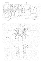
- FIG. 1 shows a device 1 according to the invention for transporting container groups 10. More precisely, these are containers of 6 containers, which are transported along a transport path P.
- the reference numerals 2 relate respectively to first conveying elements, which here contact the respective container groups 10 laterally and convey along the transport path P.
- the individual first conveying elements 2 are each formed (stationary) on a circulating carrier 6.
- the reference numeral 16 denotes a support device which supports the containers or container groups 10. This may be a circulating chain on which the containers or container groups 10 are transported.
- the reference numeral 18 denotes lateral (stationary) carrier, against which in turn the support means 16 can be supported.
- the transport chain is shown here only simplified, but it can preferably be a fully circumferential chain, so that a total of a movable support surface for the containers or containers 10 is formed.
- the support means 16 advantageously move at a constant speed, in particular along the transport path P.
- the reference numeral 20 roughly indicates a drive device which serves to move the individual conveying elements 2.
- a plurality of electromagnets can be arranged on the carrier, which are each independently controllable in the manner of a linear motor and the individual conveying elements 2 can move.
- the reference numeral 30 roughly indicates a control device which controls the movements of the individual conveying elements 2.
- a distance D between the individual containers along the transport path P is reduced, ie the individual conveying elements 2 are controlled such that the distance of the incoming container decreases from right to left.
- a plurality of further (not shown) conveying elements 2 can be arranged, which again move along the carrier 6 in the counterclockwise direction.
- the reference numeral 24 denotes a main body of the individual conveying elements, which is movably arranged on the carrier 6.
- the reference numeral 4 designate second conveying elements, which are also arranged to be movable on a second carrier 8 and independently controllable. These second conveying elements also each have base body 44.
- the containers 10 are respectively received or clamped between a first conveying element 2 and a second conveying element 4 and transported in this way.
- a conveying element 2 and a conveying element 4 assigned to it each move at least in sections at the same speed.
- the first conveying elements 2 and the second conveying elements 4 move in mutually opposite directions of rotation.
- the reference numeral 22 denotes a position detecting means which serves to determine the positions of the individual conveying elements relative to the carrier. Depending on this specific position, the movement of the conveying elements 2 can be regulated. Corresponding position detection devices can also be present for the second conveying elements 4.
- the reference numeral 5 denotes the transport unit in its entirety.
- FIG. 2a shows a sectional view along the line AA FIG. 1 , It can be seen here again the two carriers 6 and 8, on which the conveying elements 2 and 4 are arranged.
- the reference numeral 7 roughly indicates a permanent magnet which is arranged on the individual conveying elements 4, respectively.
- This permanent magnet acts together with an electromagnet or a plurality of electromagnets 17 which are arranged on the carrier 8 (and also on the carrier 6), in order in this way to achieve the movement of the individual conveying elements 2 and 4.
- a first contacting body 12, which is arranged on the first conveying element 2, and a second contacting body 14, which is arranged on the conveying element 4, can also be seen here.
- the container 10 is received between these twomaschineier Congressn.
- the support means 16, which serves to support the container 10 and which in turn is supported against a support 18.
- the drive for the support devices 16 is not shown here.
- the contacting elements 12, 14 can be designed to be elastic or spring-mounted.
- the conveying elements 2, 4 can engage behind the respective carriers 6, 8 so as to be held thereon.
- the carrier 6, 8 recesses 52 may have, in which projections of the respective counselelemete 2, 4 engage so as to improve the leadership. It would also be conceivable that air pressure is used to reduce friction between the individual conveying elements 2, 4 and their respective carriers 6, 8.
- FIG. 2b shows a further illustration of the device according to the invention.
- the conveying elements 2 and 4 can be kept movable, for example by means of rollers relative to the carriers 6 and 8, but it would also be a purely magnetic guide conceivable, or even a sliding connection.
- a further support means could be provided, which supports the two conveying elements 2 and 4 and with respect to these these can roll, for example.
- FIG. 3 shows a further embodiment, which serves for transporting containers 10 here.
- a plurality of first conveying elements 2 is provided, which each contact the containers with Kunststoffierêtn 12.
- a distance D between the containers from right to left is also reduced so far that they can exactly engage in a single-stroke 48, which has a plurality of recesses 46 on its outer periphery.
- support devices 16 shown only schematically, such as a transport chain, are also provided here.
- FIG. 3 shown device also has a plurality of second conveying elements 4, which also move along the transport path P.
- the individual containers 10 are each received between a conveyor element 2 and a second conveyor element 4. More specifically, the containers are here contacted on opposite sides of the respective Maisier Sciencesn 12 and 14 and as it were clamped along the transport path P.
- FIG. 4a shows a view along the line AA FIG. 3 , It can be seen here again the two conveying elements 2 and 4, which are arranged in each case movably on the carriers 6 and 8.
- the reference numeral 7 characterizes again roughly schematically a permanent magnet which is arranged on the respective conveying elements 4 (and correspondingly on the conveying elements 2).
- the reference numeral 17 here again denotes an electromagnet or a row or a plurality of electromagnets which serve to move the individual conveying elements 2 and 4.
- FIG. 4b shows another view of the in FIG. 2 shown device. It can be seen here again the support means 16, which serves to support the containers. This support device is arranged here in the longitudinal direction L of the containers 10 below the containers.
- the conveying elements 2 and 4 take here also at the same time a stabilization of the containers in the direction R, i. was perpendicular to the transport path P, so that the containers can not tilt or fall sideways.
- the two contacting elements 12 and 14 are here in each case movably arranged with respect to their base bodies 24 and 44. In this way, a rotation of the containers can be effected.
Landscapes
- Engineering & Computer Science (AREA)
- Mechanical Engineering (AREA)
- Non-Mechanical Conveyors (AREA)
- Attitude Control For Articles On Conveyors (AREA)
Applications Claiming Priority (1)
| Application Number | Priority Date | Filing Date | Title |
|---|---|---|---|
| DE102011016855.9A DE102011016855B4 (de) | 2011-04-13 | 2011-04-13 | Verfahren und Vorrichtung zum Transportieren von Behältnissen oder Behältnisgebinden |
Publications (2)
| Publication Number | Publication Date |
|---|---|
| EP2511203A1 true EP2511203A1 (fr) | 2012-10-17 |
| EP2511203B1 EP2511203B1 (fr) | 2017-05-17 |
Family
ID=46025418
Family Applications (1)
| Application Number | Title | Priority Date | Filing Date |
|---|---|---|---|
| EP12162836.6A Active EP2511203B1 (fr) | 2011-04-13 | 2012-04-02 | Procédé et dispositif de transport de récipients ou de paquets de récipients |
Country Status (4)
| Country | Link |
|---|---|
| US (1) | US8776985B2 (fr) |
| EP (1) | EP2511203B1 (fr) |
| CN (1) | CN102807062B (fr) |
| DE (1) | DE102011016855B4 (fr) |
Cited By (9)
| Publication number | Priority date | Publication date | Assignee | Title |
|---|---|---|---|---|
| WO2014090462A1 (fr) * | 2012-12-14 | 2014-06-19 | Robert Bosch Gmbh | Dispositif de remplissage de contenants à entraînement linéaire |
| DE102013218397A1 (de) | 2013-09-13 | 2015-03-19 | Krones Ag | Vorrichtung und Verfahren zum Gruppieren von Behältern |
| WO2016102092A1 (fr) * | 2014-12-23 | 2016-06-30 | Krones Ag | Dispositif et procédé d'inspection en continu de récipients |
| EP3109189A1 (fr) | 2015-06-25 | 2016-12-28 | Sidel Participations | Dispositif de transfert pour transporter des unités d'emballage |
| EP2848382B1 (fr) | 2013-09-13 | 2017-12-13 | Krones AG | Installation de traitement de récipient dotée d'un four et d'un dispositif de formage par soufflage ayant un entraînement individuel des supports des préformes |
| WO2020244951A1 (fr) * | 2019-06-05 | 2020-12-10 | Krones Ag | Procédé et dispositif de distribution et/ou de groupement de récipients |
| EP3626634B1 (fr) | 2018-09-20 | 2021-08-25 | Krones Aktiengesellschaft | Dispositif de manipulation et / ou d'emballage et procédé d'emballage des articles |
| IT202000008479A1 (it) | 2020-04-21 | 2021-10-21 | Kosme Srl Unipersonale | Dispositivo di trasporto per il trasporto di contenitori |
| EP3932838A1 (fr) * | 2020-06-29 | 2022-01-05 | Siemens Aktiengesellschaft | Procédé et système de transport permettant de manipuler des marchandises de détail sur une voie de transport |
Families Citing this family (44)
| Publication number | Priority date | Publication date | Assignee | Title |
|---|---|---|---|---|
| DE102011075176A1 (de) * | 2011-05-03 | 2012-11-08 | Robert Bosch Gmbh | Verfahren zum Betreiben eines elektromagnetischen Transfersystems und Transfersystem |
| CN102980729B (zh) * | 2012-12-31 | 2016-01-06 | 中国大冢制药有限公司 | 塑料瓶输液制剂多种规格同瓶型微孔检查机出口夹瓶机构 |
| DE102013109840A1 (de) * | 2013-09-09 | 2015-03-12 | Krones Ag | Vorrichtung und Verfahren zum Komprimieren von Behältnissen |
| EP2889238A1 (fr) * | 2013-12-31 | 2015-07-01 | Sidel S.p.a. Con Socio Unico | Dispositif de transfert d'articles le long d'un trajet |
| DE102014103632A1 (de) * | 2014-03-17 | 2015-09-17 | Krones Ag | Vorrichtung und Verfahren zum Transport von Behältern in einer Behälterbehandlungsanlage |
| CH709593A1 (de) * | 2014-05-05 | 2015-11-13 | Soudronic Ag | Magnetische Aufstellvorrichtung für Dosenzargen. |
| CN105197499A (zh) * | 2014-06-27 | 2015-12-30 | 江南大学 | 一种新型传送带 |
| EP2980010B1 (fr) * | 2014-07-31 | 2017-08-30 | Sidel S.p.a. Con Socio Unico | Dispositif pour remplir et boucher des récipients |
| DE102014225529A1 (de) | 2014-12-11 | 2016-06-16 | Robert Bosch Gmbh | Transportvorrichtung für eine Verpackungsmaschine |
| US9688473B2 (en) | 2015-03-02 | 2017-06-27 | Lorin Reed | Conveying systems and methods of use |
| MX2019002782A (es) | 2016-09-09 | 2019-09-04 | Procter & Gamble | Sistema y método para llenar simultáneamente recipientes con diferentes composiciones de fluidos. |
| CN109661623A (zh) | 2016-09-09 | 2019-04-19 | 宝洁公司 | 用于在单条生产线上同时生产不同产品的方法 |
| CN109690430B (zh) | 2016-09-09 | 2022-06-24 | 宝洁公司 | 基于需求生产产品的系统和方法 |
| US10640249B2 (en) | 2016-09-09 | 2020-05-05 | The Procter & Gamble Company | Track system for creating finished products |
| EP3509979B1 (fr) * | 2016-09-09 | 2023-06-14 | The Procter & Gamble Company | Système et procédé pour diriger indépendamment des véhicules et livrer des réceptacles et des fermetures à des postes fonctionnels individuels |
| MX2019002780A (es) | 2016-09-09 | 2019-09-04 | Procter & Gamble | Sistema y método para llenar simultáneamente recipientes de formas y/o tamaños diferentes. |
| CN109661624B (zh) | 2016-09-09 | 2022-10-25 | 宝洁公司 | 用于独立地引导装载容器的载具以创建不同成品的系统和方法 |
| US10442629B2 (en) | 2016-09-09 | 2019-10-15 | The Procter & Gamble Company | Vacuum holder and carrier with autonomous vacuum |
| CN106809594B (zh) * | 2017-03-20 | 2023-03-17 | 四川科伦药业股份有限公司 | 用于输液瓶输送线上的双压瓶输液瓶检漏系统 |
| DE102017215455A1 (de) * | 2017-09-04 | 2019-03-07 | Krones Ag | Transportvorrichtung zum Transportieren von Pucks |
| CA3082906C (fr) | 2017-11-22 | 2023-01-03 | Lorin Reed | Equipement de transport et de dimensionnement de produit perfectionne |
| IT201800002805A1 (it) * | 2018-02-19 | 2019-08-19 | Makro Labelling Srl | Macchina per il trattamento di contenitori |
| US11345554B2 (en) | 2018-04-10 | 2022-05-31 | The Procter & Gamble Company | Method and apparatus for flexibly assembling packages of absorbent articles |
| CN111532681B (zh) * | 2018-10-15 | 2021-08-06 | 吴连生 | 一种进出口传送检查设备 |
| CN109592355B (zh) * | 2018-11-28 | 2020-09-11 | 新沂市锡沂高新材料产业技术研究院有限公司 | 一种插轴设备 |
| EP3718913A1 (fr) * | 2019-04-04 | 2020-10-07 | Sidel Participations | Machine d'étiquetage conçue pour appliquer des étiquettes sur des articles contenant un produit pouvant être versé |
| AU2020278663B2 (en) * | 2019-05-21 | 2026-04-09 | Westrock Packaging Systems, Llc | Flexible pitch product metering system |
| EP3977605B1 (fr) * | 2019-05-28 | 2023-04-26 | B&R Industrial Automation GmbH | Dispositif de transport |
| US11713147B2 (en) | 2019-07-30 | 2023-08-01 | Anheuser-Busch Inbev S.A. | Article picking and treating apparatus |
| MX2022001248A (es) | 2019-07-30 | 2022-05-10 | Anheuser Busch Inbev Sa | Aparato desapilador. |
| EP4003719A1 (fr) | 2019-07-30 | 2022-06-01 | Anheuser-Busch InBev S.A. | Outil de mise en forme d'emballages secondaires |
| WO2021019012A1 (fr) | 2019-07-30 | 2021-02-04 | Anheuser-Busch Inbev S.A. | Appareil d'emballage |
| BR112022001661A2 (pt) | 2019-07-30 | 2022-03-22 | Anheuser Busch Inbev Sa | Aparelho de embalagem para empacotamento de embalagens, método para empacotamento de embalagem e uso do aparelho |
| US12036102B2 (en) * | 2019-09-17 | 2024-07-16 | Fameccanica.Data S.P.A. | Packaging plant for groups of hygienic absorbent articles, transport apparatus and related methods |
| JP7458867B2 (ja) * | 2020-04-08 | 2024-04-01 | 三菱重工機械システム株式会社 | 切り離し装置および切り離し方法 |
| CA3180822A1 (fr) | 2020-06-04 | 2021-12-09 | Wim Dekocker | Systeme d'emballage pour l'assemblage d'un emballage |
| WO2022010678A2 (fr) * | 2020-07-09 | 2022-01-13 | Laitram, L.L.C. | Appareil et procédés de commande dynamique de l'espacement d'objets transportés |
| BE1028746B1 (nl) | 2020-10-27 | 2022-05-24 | Anheuser Busch Inbev | Een systeem voor het hanteren van afzonderlijke primaire verpakkingshouders |
| EP4259559A1 (fr) * | 2020-12-11 | 2023-10-18 | Laitram, L.L.C. | Système de transfert de convoyeur |
| BE1028934B1 (nl) | 2020-12-23 | 2022-07-18 | Anheuser Busch Inbev Sa | Producthanteringsapparaten, -systemen en geassocieerde werkwijzen |
| US12577056B2 (en) * | 2021-05-27 | 2026-03-17 | Vivet Technology LLC | Branch assembly system and method |
| BR102021018108A2 (pt) | 2021-09-13 | 2023-03-28 | Freed Participaçoes S/A | Esteira transportadora tracionada por motor de indução linear com primário de dupla face e secundário longo seccionado |
| CN114180264B (zh) * | 2021-12-15 | 2023-12-05 | 北新建材(苏州)有限公司 | 一种过渡式石膏板输送装置 |
| WO2024153982A1 (fr) * | 2023-01-16 | 2024-07-25 | Makro Labelling S.R.L. | Appareil pour le mouvement contrôlé de récipients |
Citations (5)
| Publication number | Priority date | Publication date | Assignee | Title |
|---|---|---|---|---|
| DE19505997A1 (de) * | 1995-02-21 | 1996-08-22 | 4 P Nicolaus Kempten Gmbh | Eingruppierung |
| EP1123886A1 (fr) * | 2000-02-09 | 2001-08-16 | SIG Pack Systems AG | Dispositif de transport de produits entre au moins deux postes de travail |
| WO2003105324A1 (fr) * | 2002-06-05 | 2003-12-18 | Jacobs Automation Llc | Systeme de deplacement commande |
| WO2008022296A2 (fr) * | 2006-08-18 | 2008-02-21 | Meadwestvaco Packaging Systems Llc | Appareil de mesure avec moyen de commande d'outil indépendant |
| DE102008040204A1 (de) * | 2008-07-07 | 2010-01-14 | Robert Bosch Gmbh | Vorrichtung und Verfahren zum Transportieren von Produkten mit Linearantrieb |
Family Cites Families (20)
| Publication number | Priority date | Publication date | Assignee | Title |
|---|---|---|---|---|
| US3074533A (en) * | 1961-02-28 | 1963-01-22 | Owens Illinois Glass Co | Container handling apparatus |
| US3469673A (en) | 1967-06-27 | 1969-09-30 | Mead Corp | Correlator apparatus |
| US3635322A (en) | 1970-02-24 | 1972-01-18 | Emhart Corp | Conveyor system for dividing a line of articles into several discrete lanes |
| US4285185A (en) | 1979-08-29 | 1981-08-25 | Certipak Corporation | Article carrier feeding and control apparatus |
| US4577745A (en) | 1983-03-15 | 1986-03-25 | The Mead Corporation | Apparatus for arranging articles in groups |
| IE56387B1 (en) | 1983-04-22 | 1991-07-17 | Mead Corp | Mechanism for spacing and conveying articles in a packaging machine |
| US4982556A (en) | 1989-05-09 | 1991-01-08 | Tisma Machine Corporation | Modularly constructed automatic packaging machine |
| WO1996027544A1 (fr) | 1995-03-06 | 1996-09-12 | Sig Schweizerische Industrie-Gesellschaft | Dispositif de transport de produits entre divers postes |
| IT1294101B1 (it) | 1997-07-18 | 1999-03-22 | Sasib Beverage S P A Ora Sasib | Procedimento e dispositivo di arresto ammortizzato ed accompagnamento di contenitori, in linea di trasporto per contenitori. |
| US6360873B1 (en) | 1997-09-19 | 2002-03-26 | The Mead Corporation | Article grouping mechanism |
| US6481558B1 (en) * | 1998-12-18 | 2002-11-19 | Asyst Technologies, Inc. | Integrated load port-conveyor transfer system |
| US6202392B1 (en) | 1999-09-13 | 2001-03-20 | R. A. Jones & Co. Inc. | Flexible tissue handling apparatus |
| US6182814B1 (en) | 2000-03-03 | 2001-02-06 | Sig Pack, Inc., Doboy Division | Inline vacuum slug feeder |
| AU2002221634B2 (en) * | 2000-09-28 | 2007-04-26 | Dematic Corp. | Positive displacement shoe and slat sorter apparatus and method |
| AU783789B2 (en) * | 2001-02-07 | 2005-12-08 | Denipro Ag | Conveyor system |
| US7134258B2 (en) | 2001-12-05 | 2006-11-14 | R.A. Jones & Co. Inc. | Packaging apparatus and methods |
| DE102004042474A1 (de) | 2004-09-02 | 2006-03-23 | Krones Ag | Vorrichtung zum Gruppieren von Stückgut |
| DE102009002609A1 (de) | 2009-04-23 | 2010-10-28 | Robert Bosch Gmbh | Umlaufende Transportvorrichtung mit verbessertem Antriebskonzept |
| IT1403851B1 (it) | 2011-02-08 | 2013-11-08 | Ct Pack Srl | Macchina e metodo di confezionamento. |
| DE102011103447A1 (de) * | 2011-06-07 | 2012-12-13 | Weber Maschinenbau Gmbh Breidenbach | Vorrichtung zum Fördern von blattartigem Transportgut |
-
2011
- 2011-04-13 DE DE102011016855.9A patent/DE102011016855B4/de active Active
-
2012
- 2012-04-02 EP EP12162836.6A patent/EP2511203B1/fr active Active
- 2012-04-03 US US13/438,607 patent/US8776985B2/en active Active
- 2012-04-12 CN CN201210107072.7A patent/CN102807062B/zh active Active
Patent Citations (5)
| Publication number | Priority date | Publication date | Assignee | Title |
|---|---|---|---|---|
| DE19505997A1 (de) * | 1995-02-21 | 1996-08-22 | 4 P Nicolaus Kempten Gmbh | Eingruppierung |
| EP1123886A1 (fr) * | 2000-02-09 | 2001-08-16 | SIG Pack Systems AG | Dispositif de transport de produits entre au moins deux postes de travail |
| WO2003105324A1 (fr) * | 2002-06-05 | 2003-12-18 | Jacobs Automation Llc | Systeme de deplacement commande |
| WO2008022296A2 (fr) * | 2006-08-18 | 2008-02-21 | Meadwestvaco Packaging Systems Llc | Appareil de mesure avec moyen de commande d'outil indépendant |
| DE102008040204A1 (de) * | 2008-07-07 | 2010-01-14 | Robert Bosch Gmbh | Vorrichtung und Verfahren zum Transportieren von Produkten mit Linearantrieb |
Cited By (21)
| Publication number | Priority date | Publication date | Assignee | Title |
|---|---|---|---|---|
| WO2014090462A1 (fr) * | 2012-12-14 | 2014-06-19 | Robert Bosch Gmbh | Dispositif de remplissage de contenants à entraînement linéaire |
| EP2848382B1 (fr) | 2013-09-13 | 2017-12-13 | Krones AG | Installation de traitement de récipient dotée d'un four et d'un dispositif de formage par soufflage ayant un entraînement individuel des supports des préformes |
| DE102013218397A1 (de) | 2013-09-13 | 2015-03-19 | Krones Ag | Vorrichtung und Verfahren zum Gruppieren von Behältern |
| DE102013218397B4 (de) | 2013-09-13 | 2024-07-04 | Krones Ag | Vorrichtung und Verfahren zum Gruppieren von Behältern |
| EP3044136B1 (fr) | 2013-09-13 | 2017-07-05 | Krones AG | Appareil et procédé pour grouper des récipients |
| US9873571B2 (en) | 2013-09-13 | 2018-01-23 | Krones Ag | Device and method for grouping containers |
| US10139351B2 (en) | 2014-12-23 | 2018-11-27 | Krones Ag | Device and method for continuously inspecting containers |
| US9995691B2 (en) | 2014-12-23 | 2018-06-12 | Krones Ag | Device and method for continuously inspecting containers |
| EP4234459A3 (fr) * | 2014-12-23 | 2023-10-25 | Krones AG | Dispositif et procédé d'inspection en continu de récipients |
| WO2016102092A1 (fr) * | 2014-12-23 | 2016-06-30 | Krones Ag | Dispositif et procédé d'inspection en continu de récipients |
| US9834392B2 (en) | 2015-06-25 | 2017-12-05 | Sidel Participations S.A.S. | Transfer device for conveying packaging units |
| EP3109189A1 (fr) | 2015-06-25 | 2016-12-28 | Sidel Participations | Dispositif de transfert pour transporter des unités d'emballage |
| EP3626634B1 (fr) | 2018-09-20 | 2021-08-25 | Krones Aktiengesellschaft | Dispositif de manipulation et / ou d'emballage et procédé d'emballage des articles |
| WO2020244951A1 (fr) * | 2019-06-05 | 2020-12-10 | Krones Ag | Procédé et dispositif de distribution et/ou de groupement de récipients |
| CN113905961A (zh) * | 2019-06-05 | 2022-01-07 | 克罗内斯股份公司 | 用于分配和/或分组容器的方法和装置 |
| US11787641B2 (en) | 2019-06-05 | 2023-10-17 | Krones Ag | Method and device for distributing and/or grouping containers |
| US11186443B2 (en) | 2020-04-21 | 2021-11-30 | Kosme S.R.L. Unipersonale | Plant for processing containers |
| EP3907162A1 (fr) | 2020-04-21 | 2021-11-10 | Kosme S.r.l. Unipersonale | Installation de traitement de contenants |
| IT202000008479A1 (it) | 2020-04-21 | 2021-10-21 | Kosme Srl Unipersonale | Dispositivo di trasporto per il trasporto di contenitori |
| EP3932838A1 (fr) * | 2020-06-29 | 2022-01-05 | Siemens Aktiengesellschaft | Procédé et système de transport permettant de manipuler des marchandises de détail sur une voie de transport |
| WO2022002510A1 (fr) * | 2020-06-29 | 2022-01-06 | Siemens Aktiengesellschaft | Procédé et système de transport pour manipuler des articles sur une voie de transport |
Also Published As
| Publication number | Publication date |
|---|---|
| CN102807062A (zh) | 2012-12-05 |
| DE102011016855B4 (de) | 2023-05-04 |
| CN102807062B (zh) | 2015-03-18 |
| DE102011016855A1 (de) | 2012-10-18 |
| US20120261233A1 (en) | 2012-10-18 |
| EP2511203B1 (fr) | 2017-05-17 |
| US8776985B2 (en) | 2014-07-15 |
Similar Documents
| Publication | Publication Date | Title |
|---|---|---|
| EP2511203B1 (fr) | Procédé et dispositif de transport de récipients ou de paquets de récipients | |
| DE102007059611B4 (de) | Verfahren und Vorrichtung zum Transportieren von Objekten | |
| EP3059190B1 (fr) | Procede et dispositif destines a la distribution et au regroupement de recipients | |
| EP2634100B1 (fr) | Machine de verrouillage de coques et procédé destiné au transport de coques | |
| EP2391562B1 (fr) | Dispositif de transport | |
| EP3501878B1 (fr) | Dispositif de transport sous forme d'un moteur linéaire à stator long | |
| EP3022138B1 (fr) | Procédé et dispositif de transport pour le réagencement d'un premier flux de contenants en un second flux de contenants | |
| EP2807097B1 (fr) | Appareil et procédé pour dévier des articles, en particulier des récipients tels que des bouteilles | |
| EP2792626B1 (fr) | Procédé et dispositif de regroupement | |
| EP3334669B1 (fr) | Dispositif de transport et procédé de transport employant un tel dispositif de transport | |
| EP3597577B1 (fr) | Dispositif et procédé permettant de tamponner des articles | |
| EP3877306B1 (fr) | Dispositif pour regrouper des contenants | |
| EP1169249B1 (fr) | Procede et dispositif pour transporter des produits en vrac | |
| EP3057891B1 (fr) | Dispositif d'écartement pour écarter des récipients | |
| EP2287079A2 (fr) | Dispositif de groupement et/ou de séparation d'articles | |
| DE102016122462A1 (de) | Vorrichtung zum Sortieren und Fördern von Behälterverschlüssen | |
| WO2014053253A1 (fr) | Dispositif de transport pour marchandises et procédé permettant de faire fonctionner un dispositif de transport | |
| EP2154090A2 (fr) | Dispositif et procédé destinés à grouper des articles | |
| EP2154073A1 (fr) | Procédé et dispositif de remplissage cadencé d'une multitude de récipients | |
| EP3932838A1 (fr) | Procédé et système de transport permettant de manipuler des marchandises de détail sur une voie de transport | |
| EP0857152B2 (fr) | Procede et dispositif pour extraire des palettes a roulettes utilisees dans la technique de stockage compact et palette a roulettes appropriee | |
| EP3480144A1 (fr) | Machine de manipulation de récipient et dispositif de transport pour récipient | |
| EP4490085B1 (fr) | Concept de commande pour transporteur à entraînement électrique linéaire | |
| EP1401611A1 (fr) | Chaine de montage | |
| WO2019048549A1 (fr) | Dispositif de transport et procédé de transport mettant en oeuvre un tel dispositif de transport |
Legal Events
| Date | Code | Title | Description |
|---|---|---|---|
| PUAI | Public reference made under article 153(3) epc to a published international application that has entered the european phase |
Free format text: ORIGINAL CODE: 0009012 |
|
| AK | Designated contracting states |
Kind code of ref document: A1 Designated state(s): AL AT BE BG CH CY CZ DE DK EE ES FI FR GB GR HR HU IE IS IT LI LT LU LV MC MK MT NL NO PL PT RO RS SE SI SK SM TR |
|
| AX | Request for extension of the european patent |
Extension state: BA ME |
|
| 17P | Request for examination filed |
Effective date: 20130417 |
|
| 17Q | First examination report despatched |
Effective date: 20130529 |
|
| GRAP | Despatch of communication of intention to grant a patent |
Free format text: ORIGINAL CODE: EPIDOSNIGR1 |
|
| STAA | Information on the status of an ep patent application or granted ep patent |
Free format text: STATUS: GRANT OF PATENT IS INTENDED |
|
| INTG | Intention to grant announced |
Effective date: 20161109 |
|
| GRAS | Grant fee paid |
Free format text: ORIGINAL CODE: EPIDOSNIGR3 |
|
| GRAA | (expected) grant |
Free format text: ORIGINAL CODE: 0009210 |
|
| STAA | Information on the status of an ep patent application or granted ep patent |
Free format text: STATUS: THE PATENT HAS BEEN GRANTED |
|
| AK | Designated contracting states |
Kind code of ref document: B1 Designated state(s): AL AT BE BG CH CY CZ DE DK EE ES FI FR GB GR HR HU IE IS IT LI LT LU LV MC MK MT NL NO PL PT RO RS SE SI SK SM TR |
|
| REG | Reference to a national code |
Ref country code: GB Ref legal event code: FG4D Free format text: NOT ENGLISH |
|
| REG | Reference to a national code |
Ref country code: CH Ref legal event code: EP |
|
| REG | Reference to a national code |
Ref country code: IE Ref legal event code: FG4D Free format text: LANGUAGE OF EP DOCUMENT: GERMAN |
|
| REG | Reference to a national code |
Ref country code: AT Ref legal event code: REF Ref document number: 894235 Country of ref document: AT Kind code of ref document: T Effective date: 20170615 |
|
| REG | Reference to a national code |
Ref country code: DE Ref legal event code: R096 Ref document number: 502012010357 Country of ref document: DE |
|
| REG | Reference to a national code |
Ref country code: NL Ref legal event code: MP Effective date: 20170517 |
|
| REG | Reference to a national code |
Ref country code: LT Ref legal event code: MG4D |
|
| PG25 | Lapsed in a contracting state [announced via postgrant information from national office to epo] |
Ref country code: HR Free format text: LAPSE BECAUSE OF FAILURE TO SUBMIT A TRANSLATION OF THE DESCRIPTION OR TO PAY THE FEE WITHIN THE PRESCRIBED TIME-LIMIT Effective date: 20170517 Ref country code: ES Free format text: LAPSE BECAUSE OF FAILURE TO SUBMIT A TRANSLATION OF THE DESCRIPTION OR TO PAY THE FEE WITHIN THE PRESCRIBED TIME-LIMIT Effective date: 20170517 Ref country code: NO Free format text: LAPSE BECAUSE OF FAILURE TO SUBMIT A TRANSLATION OF THE DESCRIPTION OR TO PAY THE FEE WITHIN THE PRESCRIBED TIME-LIMIT Effective date: 20170817 Ref country code: LT Free format text: LAPSE BECAUSE OF FAILURE TO SUBMIT A TRANSLATION OF THE DESCRIPTION OR TO PAY THE FEE WITHIN THE PRESCRIBED TIME-LIMIT Effective date: 20170517 Ref country code: FI Free format text: LAPSE BECAUSE OF FAILURE TO SUBMIT A TRANSLATION OF THE DESCRIPTION OR TO PAY THE FEE WITHIN THE PRESCRIBED TIME-LIMIT Effective date: 20170517 Ref country code: GR Free format text: LAPSE BECAUSE OF FAILURE TO SUBMIT A TRANSLATION OF THE DESCRIPTION OR TO PAY THE FEE WITHIN THE PRESCRIBED TIME-LIMIT Effective date: 20170818 |
|
| PG25 | Lapsed in a contracting state [announced via postgrant information from national office to epo] |
Ref country code: SE Free format text: LAPSE BECAUSE OF FAILURE TO SUBMIT A TRANSLATION OF THE DESCRIPTION OR TO PAY THE FEE WITHIN THE PRESCRIBED TIME-LIMIT Effective date: 20170517 Ref country code: RS Free format text: LAPSE BECAUSE OF FAILURE TO SUBMIT A TRANSLATION OF THE DESCRIPTION OR TO PAY THE FEE WITHIN THE PRESCRIBED TIME-LIMIT Effective date: 20170517 Ref country code: IS Free format text: LAPSE BECAUSE OF FAILURE TO SUBMIT A TRANSLATION OF THE DESCRIPTION OR TO PAY THE FEE WITHIN THE PRESCRIBED TIME-LIMIT Effective date: 20170917 Ref country code: NL Free format text: LAPSE BECAUSE OF FAILURE TO SUBMIT A TRANSLATION OF THE DESCRIPTION OR TO PAY THE FEE WITHIN THE PRESCRIBED TIME-LIMIT Effective date: 20170517 Ref country code: BG Free format text: LAPSE BECAUSE OF FAILURE TO SUBMIT A TRANSLATION OF THE DESCRIPTION OR TO PAY THE FEE WITHIN THE PRESCRIBED TIME-LIMIT Effective date: 20170817 Ref country code: PL Free format text: LAPSE BECAUSE OF FAILURE TO SUBMIT A TRANSLATION OF THE DESCRIPTION OR TO PAY THE FEE WITHIN THE PRESCRIBED TIME-LIMIT Effective date: 20170517 Ref country code: LV Free format text: LAPSE BECAUSE OF FAILURE TO SUBMIT A TRANSLATION OF THE DESCRIPTION OR TO PAY THE FEE WITHIN THE PRESCRIBED TIME-LIMIT Effective date: 20170517 |
|
| PG25 | Lapsed in a contracting state [announced via postgrant information from national office to epo] |
Ref country code: EE Free format text: LAPSE BECAUSE OF FAILURE TO SUBMIT A TRANSLATION OF THE DESCRIPTION OR TO PAY THE FEE WITHIN THE PRESCRIBED TIME-LIMIT Effective date: 20170517 Ref country code: CZ Free format text: LAPSE BECAUSE OF FAILURE TO SUBMIT A TRANSLATION OF THE DESCRIPTION OR TO PAY THE FEE WITHIN THE PRESCRIBED TIME-LIMIT Effective date: 20170517 Ref country code: DK Free format text: LAPSE BECAUSE OF FAILURE TO SUBMIT A TRANSLATION OF THE DESCRIPTION OR TO PAY THE FEE WITHIN THE PRESCRIBED TIME-LIMIT Effective date: 20170517 Ref country code: RO Free format text: LAPSE BECAUSE OF FAILURE TO SUBMIT A TRANSLATION OF THE DESCRIPTION OR TO PAY THE FEE WITHIN THE PRESCRIBED TIME-LIMIT Effective date: 20170517 Ref country code: SK Free format text: LAPSE BECAUSE OF FAILURE TO SUBMIT A TRANSLATION OF THE DESCRIPTION OR TO PAY THE FEE WITHIN THE PRESCRIBED TIME-LIMIT Effective date: 20170517 |
|
| REG | Reference to a national code |
Ref country code: DE Ref legal event code: R026 Ref document number: 502012010357 Country of ref document: DE |
|
| PLBI | Opposition filed |
Free format text: ORIGINAL CODE: 0009260 |
|
| PLAX | Notice of opposition and request to file observation + time limit sent |
Free format text: ORIGINAL CODE: EPIDOSNOBS2 |
|
| PG25 | Lapsed in a contracting state [announced via postgrant information from national office to epo] |
Ref country code: SM Free format text: LAPSE BECAUSE OF FAILURE TO SUBMIT A TRANSLATION OF THE DESCRIPTION OR TO PAY THE FEE WITHIN THE PRESCRIBED TIME-LIMIT Effective date: 20170517 |
|
| REG | Reference to a national code |
Ref country code: FR Ref legal event code: PLFP Year of fee payment: 7 |
|
| 26 | Opposition filed |
Opponent name: C.E.R.M.E.X. CONSTRUCTIONS ETUDES ET RECHERCHES DE Effective date: 20180216 |
|
| PG25 | Lapsed in a contracting state [announced via postgrant information from national office to epo] |
Ref country code: SI Free format text: LAPSE BECAUSE OF FAILURE TO SUBMIT A TRANSLATION OF THE DESCRIPTION OR TO PAY THE FEE WITHIN THE PRESCRIBED TIME-LIMIT Effective date: 20170517 |
|
| PLBB | Reply of patent proprietor to notice(s) of opposition received |
Free format text: ORIGINAL CODE: EPIDOSNOBS3 |
|
| PG25 | Lapsed in a contracting state [announced via postgrant information from national office to epo] |
Ref country code: MT Free format text: LAPSE BECAUSE OF FAILURE TO SUBMIT A TRANSLATION OF THE DESCRIPTION OR TO PAY THE FEE WITHIN THE PRESCRIBED TIME-LIMIT Effective date: 20170517 |
|
| PG25 | Lapsed in a contracting state [announced via postgrant information from national office to epo] |
Ref country code: MC Free format text: LAPSE BECAUSE OF FAILURE TO SUBMIT A TRANSLATION OF THE DESCRIPTION OR TO PAY THE FEE WITHIN THE PRESCRIBED TIME-LIMIT Effective date: 20170517 |
|
| REG | Reference to a national code |
Ref country code: CH Ref legal event code: PL |
|
| REG | Reference to a national code |
Ref country code: BE Ref legal event code: MM Effective date: 20180430 |
|
| GBPC | Gb: european patent ceased through non-payment of renewal fee |
Effective date: 20180402 |
|
| REG | Reference to a national code |
Ref country code: IE Ref legal event code: MM4A |
|
| PG25 | Lapsed in a contracting state [announced via postgrant information from national office to epo] |
Ref country code: LU Free format text: LAPSE BECAUSE OF NON-PAYMENT OF DUE FEES Effective date: 20180402 |
|
| PG25 | Lapsed in a contracting state [announced via postgrant information from national office to epo] |
Ref country code: GB Free format text: LAPSE BECAUSE OF NON-PAYMENT OF DUE FEES Effective date: 20180402 Ref country code: LI Free format text: LAPSE BECAUSE OF NON-PAYMENT OF DUE FEES Effective date: 20180430 Ref country code: CH Free format text: LAPSE BECAUSE OF NON-PAYMENT OF DUE FEES Effective date: 20180430 Ref country code: BE Free format text: LAPSE BECAUSE OF NON-PAYMENT OF DUE FEES Effective date: 20180430 |
|
| PG25 | Lapsed in a contracting state [announced via postgrant information from national office to epo] |
Ref country code: IE Free format text: LAPSE BECAUSE OF NON-PAYMENT OF DUE FEES Effective date: 20180402 |
|
| PG25 | Lapsed in a contracting state [announced via postgrant information from national office to epo] |
Ref country code: TR Free format text: LAPSE BECAUSE OF FAILURE TO SUBMIT A TRANSLATION OF THE DESCRIPTION OR TO PAY THE FEE WITHIN THE PRESCRIBED TIME-LIMIT Effective date: 20170517 |
|
| PG25 | Lapsed in a contracting state [announced via postgrant information from national office to epo] |
Ref country code: PT Free format text: LAPSE BECAUSE OF FAILURE TO SUBMIT A TRANSLATION OF THE DESCRIPTION OR TO PAY THE FEE WITHIN THE PRESCRIBED TIME-LIMIT Effective date: 20170517 Ref country code: HU Free format text: LAPSE BECAUSE OF FAILURE TO SUBMIT A TRANSLATION OF THE DESCRIPTION OR TO PAY THE FEE WITHIN THE PRESCRIBED TIME-LIMIT; INVALID AB INITIO Effective date: 20120402 |
|
| PG25 | Lapsed in a contracting state [announced via postgrant information from national office to epo] |
Ref country code: MK Free format text: LAPSE BECAUSE OF NON-PAYMENT OF DUE FEES Effective date: 20170517 Ref country code: CY Free format text: LAPSE BECAUSE OF FAILURE TO SUBMIT A TRANSLATION OF THE DESCRIPTION OR TO PAY THE FEE WITHIN THE PRESCRIBED TIME-LIMIT Effective date: 20170517 |
|
| PG25 | Lapsed in a contracting state [announced via postgrant information from national office to epo] |
Ref country code: AL Free format text: LAPSE BECAUSE OF FAILURE TO SUBMIT A TRANSLATION OF THE DESCRIPTION OR TO PAY THE FEE WITHIN THE PRESCRIBED TIME-LIMIT Effective date: 20170517 |
|
| APBM | Appeal reference recorded |
Free format text: ORIGINAL CODE: EPIDOSNREFNO |
|
| APBP | Date of receipt of notice of appeal recorded |
Free format text: ORIGINAL CODE: EPIDOSNNOA2O |
|
| APAH | Appeal reference modified |
Free format text: ORIGINAL CODE: EPIDOSCREFNO |
|
| APBM | Appeal reference recorded |
Free format text: ORIGINAL CODE: EPIDOSNREFNO |
|
| APBP | Date of receipt of notice of appeal recorded |
Free format text: ORIGINAL CODE: EPIDOSNNOA2O |
|
| APBQ | Date of receipt of statement of grounds of appeal recorded |
Free format text: ORIGINAL CODE: EPIDOSNNOA3O |
|
| APBQ | Date of receipt of statement of grounds of appeal recorded |
Free format text: ORIGINAL CODE: EPIDOSNNOA3O |
|
| APAH | Appeal reference modified |
Free format text: ORIGINAL CODE: EPIDOSCREFNO |
|
| P01 | Opt-out of the competence of the unified patent court (upc) registered |
Effective date: 20230523 |
|
| APBU | Appeal procedure closed |
Free format text: ORIGINAL CODE: EPIDOSNNOA9O |
|
| REG | Reference to a national code |
Ref country code: DE Ref legal event code: R100 Ref document number: 502012010357 Country of ref document: DE |
|
| PLCK | Communication despatched that opposition was rejected |
Free format text: ORIGINAL CODE: EPIDOSNREJ1 |
|
| STAA | Information on the status of an ep patent application or granted ep patent |
Free format text: STATUS: OPPOSITION REJECTED |
|
| PLBN | Opposition rejected |
Free format text: ORIGINAL CODE: 0009273 |
|
| 27O | Opposition rejected |
Effective date: 20231122 |
|
| PGFP | Annual fee paid to national office [announced via postgrant information from national office to epo] |
Ref country code: DE Payment date: 20250305 Year of fee payment: 14 |
|
| PGFP | Annual fee paid to national office [announced via postgrant information from national office to epo] |
Ref country code: AT Payment date: 20250325 Year of fee payment: 14 |
|
| PGFP | Annual fee paid to national office [announced via postgrant information from national office to epo] |
Ref country code: IT Payment date: 20260320 Year of fee payment: 15 |
|
| PGFP | Annual fee paid to national office [announced via postgrant information from national office to epo] |
Ref country code: FR Payment date: 20260309 Year of fee payment: 15 |