EP2511628A2 - Heizanlage für Einkaufszentrum - Google Patents
Heizanlage für Einkaufszentrum Download PDFInfo
- Publication number
- EP2511628A2 EP2511628A2 EP12290122A EP12290122A EP2511628A2 EP 2511628 A2 EP2511628 A2 EP 2511628A2 EP 12290122 A EP12290122 A EP 12290122A EP 12290122 A EP12290122 A EP 12290122A EP 2511628 A2 EP2511628 A2 EP 2511628A2
- Authority
- EP
- European Patent Office
- Prior art keywords
- circuit
- valve
- air conditioning
- cold
- pump
- Prior art date
- Legal status (The legal status is an assumption and is not a legal conclusion. Google has not performed a legal analysis and makes no representation as to the accuracy of the status listed.)
- Withdrawn
Links
Images




Classifications
-
- F—MECHANICAL ENGINEERING; LIGHTING; HEATING; WEAPONS; BLASTING
- F25—REFRIGERATION OR COOLING; COMBINED HEATING AND REFRIGERATION SYSTEMS; HEAT PUMP SYSTEMS; MANUFACTURE OR STORAGE OF ICE; LIQUEFACTION SOLIDIFICATION OF GASES
- F25B—REFRIGERATION MACHINES, PLANTS OR SYSTEMS; COMBINED HEATING AND REFRIGERATION SYSTEMS; HEAT PUMP SYSTEMS
- F25B25/00—Machines, plants or systems, using a combination of modes of operation covered by two or more of the groups F25B1/00 - F25B23/00
-
- F—MECHANICAL ENGINEERING; LIGHTING; HEATING; WEAPONS; BLASTING
- F25—REFRIGERATION OR COOLING; COMBINED HEATING AND REFRIGERATION SYSTEMS; HEAT PUMP SYSTEMS; MANUFACTURE OR STORAGE OF ICE; LIQUEFACTION SOLIDIFICATION OF GASES
- F25B—REFRIGERATION MACHINES, PLANTS OR SYSTEMS; COMBINED HEATING AND REFRIGERATION SYSTEMS; HEAT PUMP SYSTEMS
- F25B29/00—Combined heating and refrigeration systems, e.g. operating alternately or simultaneously
- F25B29/003—Combined heating and refrigeration systems, e.g. operating alternately or simultaneously of the compression type system
-
- F—MECHANICAL ENGINEERING; LIGHTING; HEATING; WEAPONS; BLASTING
- F25—REFRIGERATION OR COOLING; COMBINED HEATING AND REFRIGERATION SYSTEMS; HEAT PUMP SYSTEMS; MANUFACTURE OR STORAGE OF ICE; LIQUEFACTION SOLIDIFICATION OF GASES
- F25B—REFRIGERATION MACHINES, PLANTS OR SYSTEMS; COMBINED HEATING AND REFRIGERATION SYSTEMS; HEAT PUMP SYSTEMS
- F25B2400/00—Component parts or details not otherwise provided for in this subclass
- F25B2400/06—Several compression cycles arranged in parallel
-
- F—MECHANICAL ENGINEERING; LIGHTING; HEATING; WEAPONS; BLASTING
- F25—REFRIGERATION OR COOLING; COMBINED HEATING AND REFRIGERATION SYSTEMS; HEAT PUMP SYSTEMS; MANUFACTURE OR STORAGE OF ICE; LIQUEFACTION SOLIDIFICATION OF GASES
- F25B—REFRIGERATION MACHINES, PLANTS OR SYSTEMS; COMBINED HEATING AND REFRIGERATION SYSTEMS; HEAT PUMP SYSTEMS
- F25B2400/00—Component parts or details not otherwise provided for in this subclass
- F25B2400/22—Refrigeration systems for supermarkets
-
- F—MECHANICAL ENGINEERING; LIGHTING; HEATING; WEAPONS; BLASTING
- F25—REFRIGERATION OR COOLING; COMBINED HEATING AND REFRIGERATION SYSTEMS; HEAT PUMP SYSTEMS; MANUFACTURE OR STORAGE OF ICE; LIQUEFACTION SOLIDIFICATION OF GASES
- F25B—REFRIGERATION MACHINES, PLANTS OR SYSTEMS; COMBINED HEATING AND REFRIGERATION SYSTEMS; HEAT PUMP SYSTEMS
- F25B2400/00—Component parts or details not otherwise provided for in this subclass
- F25B2400/24—Thermal storage element
Definitions
- the invention relates to a thermal installation for buildings of the shopping center type.
- a thermal installation includes the production of food cold and air conditioning.
- it also includes heating by direct production and / or recovery, and is coupled where appropriate to a cogeneration energy production system.
- the invention improves the situation.
- the invention proposes a heat installation for a shopping center, comprising a first refrigeration unit connected to a food cold circuit, and a second refrigeration unit connected to an air conditioning circuit, said air conditioning circuit comprising a storage device for storage. cold.
- This installation also comprises two links between the food cold circuit and the air conditioning circuit, each link being controlled by a control valve.
- shopping center therefore aims at both a shopping center including or not a hypermarket, and a hypermarket alone.
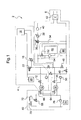
- the figure 1 represents a first embodiment of a shopping center heat installation according to the invention.
- the thermal installation 2 comprises a food cold circuit 4 and an air conditioning circuit 6.
- the food cold circuit 4 is mainly dedicated to the management of the temperature of the refrigerant fluid in the showcases, gondolas and other cold rooms, while the Air conditioning circuit 6 is dedicated to the management of air conditioning in the mall.
- the food cold circuit 4 comprises a first refrigerating unit 10, a stop valve 12, a pump 16, showcases, gondolas and cold rooms 18, an expansion tank 20, a pressure drop valve 22, and a pump 24.
- the first cooling unit 10 cools the refrigerant fluid to supply the evaporator circuit in a branch called "distribution branch", which comprises the motorized shut-off valve 12. Once it has passed through the distribution branch, the coolant fluid is slightly warmed because it gave up cold during its crossing, and it has a temperature of about 5 ° C more than at its outlet of the first refrigerating unit 10.
- the refrigerant fluid then returns to the first refrigerating unit 10 through a so-called "return branch” branch, which comprises the pump 24. It is the pump 24 which reinjects the refrigerant fluid of the return branch into the refrigeration unit 10 to start again. the loop.
- the shutoff valve 12 is motorized, and serves to stop the first refrigeration unit 10. Downstream of the stop valve 12, the distribution branch comprises the pump 16. In the example described here, the pump 16 is adjustable in frequency, depending on the pressure. This adjustment depends on the measurements taken from the membrane pressure drop valve 22, which is arranged upstream of the pump 16 between the distribution branch and the return branch.
- the distribution branch ends with the connection between the pump 16 and the showcases, gondolas and cold rooms 18 for their supply of coolant fluid.
- the return branch begins downstream of the windows, gondolas and cold rooms 18, and extends to the expansion vessel 20, upstream of which is connected the pressure drop valve 22, and ends with the pump 24.
- the air-conditioning circuit 6 comprises a second refrigeration unit 30, a shut-off valve 32, a cold storage circuit 34, an adjustment valve 36, a pump 38, a sensor 40, an exchanger 42, an expansion vessel 44, a shutoff valve 46, a shutoff valve 48, and a pump 50.
- the cold storage circuit 34 includes a shutoff valve 52, a sensor 54, and a cold storage device 56.
- the second refrigerating unit 30 receives the slightly heated secondary refrigerant fluid from the pump 50 in a branch referred to as a "return branch" of the evaporator circuit of the second refrigeration unit 30, and cools it to reintroduce it into a branch designated as a "distribution branch” of the evaporator circuit of the second refrigerating unit 30, and which comprises the valve 32.
- the stop valve 32 is motorized, and is used to stop the second refrigeration unit 30. Downstream of the stop valve 32, the distribution branch comprises the cold storage circuit 34 , whose admission is adjusted by the stop valve 52. In the example described here, the stop valve 52 is motorized. The operation of the cold storage circuit 34 will be described below.
- the distribution branch Downstream of the cold storage circuit 34, the distribution branch is connected to the inlet of the control valve 36.
- the control valve 36 is a motorized three-way valve with two inputs and one exit.
- the output path is connected to the pump 38.
- the pump 38 is motorized and supplies the exchanger 42 through the sensor 40.
- An input path is connected downstream of the cold storage circuit 34, and the other path the inlet of the control valve 36 is connected to the return branch, and thus constitutes a fluid reintroduction means in the exchanger 42.
- the exchanger 42 serves to cool the liquid of the air conditioning system of the mall.
- the sensor 40 measures the cooling requirements of the air conditioning system and makes it possible to control the valve 36 accordingly.
- the return branch starts downstream of the exchanger 42. It joins the reintroduction branch, as well as an input / output branch of the cold storage circuit 34.
- the return branch comprises the expansion vessel 44 and the stop valve 46, which is in the example described here motorized.
- the stop valve 46 is itself connected to the inlet of the pump 50 which supplies the second cooling unit 30 with heated fluid.
- the installation 2 also comprises a valve 58 and a valve 60.
- the valve 58 connects the return branch of the evaporator circuit of the first refrigeration unit 10 and the return evaporator return branch of the evaporator circuit of the second refrigeration unit 30, and is arranged between the pump 24 on the one hand and the pump 50 on the other hand.
- the valve 60 connects the distribution branch of the evaporator circuit of the first refrigeration unit 10 and the distribution branch of the evaporator circuit of the second refrigerating unit 30, and is arranged between the pump 16 on the one hand, and the stop valve 32 'somewhere else.
- the stop valve 48 is connected downstream to the stop valve 46, and a non-return valve not shown is arranged downstream between the stop valve 60, between the latter and the stop valve 48, and circulates the fluid from the distribution branch to the return branch of the evaporator circuit of the second refrigeration unit 30.
- valve 58 and the valve 60 are dispensing and stopping valves which make it possible to selectively connect or "merge" the food cold circuit 4 and the air-conditioning circuit 6.
- the description of the Figures 2 to 7 will better understand the interest of these valves.
- the condenser circuit 62 comprises a valve 64, a valve 66, a valve 68, a valve 70, an air cooler 72, an expansion tank 74 and a pump 76.
- the outputs of the valves 64 and 66 are interconnected by a branch wherein the circulation of the refrigerant fluid of the condenser circuit 62 is from the valve 64 to the valve 66.
- the valve 64 is connected to the second refrigeration unit 30, and is in the example described a motorized stop valve of the condenser circuit of the second refrigeration unit 30.
- the valve 66 is connected to the first refrigerating unit 10, and is in the example discloses a motorized shut-off valve of the condenser circuit of the first refrigerating unit 10.
- valve 68 Downstream of the valve 66, the valve 68 on the one hand, and the valve 70 and the air cooler 72 on the other hand are arranged in parallel.
- the valve 68 is a motorized control valve of the drycooler 72
- the valve 70 is a motorized shutoff valve.
- the valve 68 and the valve 70 cooperate together to control the amount of refrigerant fluid from the first refrigeration unit 10 and the second refrigeration unit 30 which passes through the air cooler 72.
- the operation of the valves 68 and 70 will be described below.
- the air cooler 72 has the function of cooling the coolant fluid therethrough. Indeed, to produce cold in the evaporator circuits of the first refrigerating unit 10 and the second refrigerating unit 30, it is necessary to remove the accumulated calories in the distribution branches.
- the condenser circuit 62 Downstream of the valves 68 and 70, the condenser circuit 62 comprises an expansion vessel 74, which is connected to a pump 76.
- the pump 76 may comprise two operating pumps and a redundancy pump, in case of failure.
- the pump 76 supplies firstly the first refrigerating unit 10 and secondly the second refrigerating unit 30 for cooling the fluid of their respective evaporator circuits.
- FIGS. 2 to 7 represent the various operating modes of the installation 2.
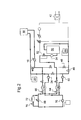
- the circuit followed by the coolant fluid in the evaporator circuits is represented by a thick line, as opposed to thin lines, which represent the parts of the evaporator circuits in which the fluid does not circulate. Arrows indicate the flow direction of the fluid.
- FIG. 2 an operating mode is shown in which the food cold circuit 4 and the air conditioning circuit 6 operate independently, in the night mode.
- the first refrigeration unit 10 is activated, the shut-off valve 12 is open, and the pumps 16 and 24 operate. As the food cold circuit 4 and the air conditioning circuit 6 are separated, the stop valves 58 and 60 are closed.
- the second refrigeration unit 30 then operates at full load to charge the cold storage device 56 in cold condition, and the refrigerant fluid at the outlet thereof joins the return branch of the evaporator circuit of the second refrigeration unit 30 towards the expansion vessel 44.
- the pump 50 is activated, the stop valve 32 and the stop valve 46 are open, and the stop valve 48 is closed.
- the condenser circuit 62 discharges the rejected calories generated by the production of cold to the evaporator circuit of the first refrigerating unit 10 and the second refrigerating unit 30.
- valve 68 When the valve 68 is closed and the valve 70 open, the fluid passes through the air cooler 72, whose fans will activate, to cool the coolant through the outside air.
- the valve 68 is controlled in opening and closing to ensure that the fluid of the condenser circuit 62 remains above 25 ° C.
- the air cooler 72 thus functions as a "valve" for evacuating too many calories.
- the operating mode of the figure 2 represents a cycle start mode.
- the temperature of the refrigerant fluid is greater in the air conditioning circuit 6, in which it is of the order of 8 ° C, than in the food cold circuit 4, in which it is of the order of - 2 ° C.
- the temperature of the refrigerant fluid in the air conditioning circuit 6 is gradually lowered, while that of the refrigerant fluid in the food cold circuit 4 remains stable. Once the temperature of the refrigerant fluid in the air conditioning circuit 6 approaches -2 ° C, the food cold circuit 4 and the air conditioning circuit 6 are ready to be fused.
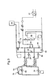
- the figure 3 represents a mode of operation in which the food cold circuit 4 and the air conditioning circuit 6 have merged.
- the first refrigerating unit 10 needs to operate at a level between 30% and 40% of its capacity. It is therefore advantageous to open the valves 58 and 60 in order to use the remaining power of the first refrigeration unit 10 for the cold storage device 56.
- the temperature in the evaporator circuit of the refrigerating unit 30 was gradually brought to -2 ° C. This temperature corresponds to that of the refrigerant fluid of the food cold circuit 4.
- valves 58 and 60 open.
- the first refrigerating unit 10 and the second cooling unit 30 then work together to charge the cold storage device 56.
- the food cold circuit 4 and the air conditioning circuit 6 have then merged.
- the cold storage device 56 When the return temperature in the return branch of the second refrigeration unit 30 reaches the temperature of -5 ° C, the cold storage device 56 is charged, and the second refrigeration unit 30 is stopped. The food cold circuit 4 and the air conditioning circuit 6 are then separated again, by closing the valves 58 and 60.
- the pump 16 of the food cold circuit 4 then operates at a level between 30% and 40% of its normal capacity for cooling the windows, gondolas and cold rooms 18, while the air conditioning circuit 6 is closed. For this, the stop valves 32 and 52 are closed, and the pump 50 is stopped.
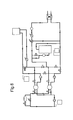
- the figure 5 represents the next mode of operation in time the operating mode of the figure 4 .
- the operating mode of the figure 5 corresponds to the use of the thermal installation 2 at the beginning of the day. During the morning, the needs for air conditioning are not maximum, and it is not necessarily useful to start emptying the cold storage device 56.
- the food cold circuit 4 then functions similar to what has been presented with the Figures 2 to 4 , with a suitable adjustment of the flow rate of the pump 16 as a function of the cold requirements for showcases, gondolas and cold rooms 18.
- the air conditioning circuit 6 then operates in a conventional manner, that is to say without using the cold storage circuit 34.
- the pumps 38 and 50 are activated, the shut-off valves 32, 46 and 48 are open, the shut-off valve 10 is closed, and the control valve 12 makes it possible to regulate the temperature of the fluid entering the exchanger 42.
- the second cooling unit 30 and the valve 36 are used to obtain a temperature of 4 ° C at the inlet of exchanger 42.
- valve 48 is closed, in order to separate the distribution branch and the return branch, while the cold storage device 56 is activated.
- the fluid of the return branch passes partly into the cold storage device 56 in which it is cooled, and mixed by the control valve 36 to maintain the set point of 4 ° C. at the inlet of the exchanger 42.
- the operation of the food cold circuit 4 is unchanged, and the pump 16 generally operates at a level between 60% and 70% of its capacity.
- the second refrigeration unit 30 and the pump 50 are stopped, and the shut-off valves 32, 46, 48 and 54 are closed.
- the cold storage device 56 is activated and the control valve 36 provides the temperature setpoint at the inlet of the exchanger 42.
- the operation of the food cold circuit 4 is unchanged, and the pump 16 generally operates at a level that depends on the need for cold food.
- This mode of operation is particularly advantageous because it makes it possible to smooth the consumption of electricity when the peak of consumption is reached. This makes it possible both to reduce the electricity bill consumed, but also to reduce the risk of overloading the grid to which the shopping center is connected.
- This mode of operation is all the more advantageous as the melting of the food cold circuit 4 and the air conditioning circuit 6 makes it possible to use an oversized cold storage device 56.
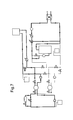
- the operating mode of the figure 7 can also be activated at any time, for example when there is a peak power consumption or a risk of saturation of the available electrical power required by various needs, including air conditioning.
- the second cooling unit 30 is then stopped, and the cold storage device 56 takes the relay, cooling the fluid before the entry of the exchanger 42.
- the installation 2 has the advantage of offering a redundant nature in the event of failure of the first refrigerating unit 4 or the second cooling unit 30.
- the thermal installation 2 allows, by the valves 58 and 60, to offer a solution to this problem, since it is possible to merge the food cold circuit 4 and the cooling circuit. 6 if a failure is detected on the first cooling unit 10 or the second cooling unit 30.
- the refrigerating units 10 and 30 have a close cold power, and each have at least two compressors with circuits independent.
- the use of the cold storage device 56 will likely be necessary to meet the needs of the exchanger 42 for the air conditioning circuit.
- the condenser circuit 62 is activated to cool their fluid.
- the condenser circuit 62 has advantageously been shown here as common to the first refrigerating unit 10 and the second refrigerating unit 30, it would be possible to provide a condenser circuit 62 for each of them.
- the figure 8 represents a second embodiment in which the thermal plant 2, which includes a heat recovery system.
- the figure 8 has been simplified, and refers only to the new elements of the installation 2 and the elements of the latter to which these elements are connected.
- the recovery elements are connected to the condenser circuit 62, by a branch called “distribution branch” which comes to collect the heated fluid of the condenser circuit 62 at the output of the connection between the valves 64 and 66, and by a branch called “return branch”, which reintroduces the cooled fluid after heat recovery downstream of the valves 68 and 70, to the expansion vessel 72.
- the heat recovery at the condenser circuit 62 can to be partial, or total.
- the maximum calorie recovery is obtained by opening the valve 68, by closing the valve 70.
- the heat output recovered is equal to the cold power added of the compressor power of the first refrigerating unit 10 and the second cooling unit 30. This represents a recovery of about 130% of the cold power. . In winter, this should cover most heat requirements in many countries.
- the distribution branch splits into two sub-branches each comprising a stop valve referenced 78 and 80 respectively.
- the stop valves 78 and 80 are motorized shut-off valves.
- the sub-branch which comprises the stop valve 78 is directed to an air treatment component 82.
- the component 82 is arranged to recover calories from the fluid of this branch to produce hot air, and which returns the cooled fluid in the return branch.
- the sub-branch which comprises the shut-off valve 80 is directed towards a sanitary water circuit 84.
- the sanitary water circuit 84 comprises a heat exchanger (not shown) which is arranged to recover calories from the fluid of this branch to produce heat. the hot water, and that returns the cooled fluid in the return branch.
- the operating modes of the installation 2 described with reference to the Figures 2 to 7 do not change with the installation of the figure 8 .
- the only change lies in the activation of the condenser circuit 2, in which the calories of the evaporator circuits are primarily removed by means of the component 82 and the circuit 84, and in which the valves 68 and 70 and the air cooler are then controlled only to evacuate excess calories not used by component 82 and circuit 84.
- the figure 9 represents a third embodiment allowing the realization of a thermal installation 2 even more advantageous.
- the thermal installation comprise the heat recovery elements of the figure 8 but it also includes redundant elements, both functional and structural.
- each of the pumps 16, 24, 38, 50 and 76 is doubled, by means of a pump which is arranged in parallel, in addition to the possible reserve pump already present for the pump 76.
- the plant 2 comprises two gas generators 90 and 92 for a cogeneration operation.
- the heat produced by the generators is then transferred for the building heating and domestic hot water production.
- the generators 90 and 92 are connected to exchangers 94 and 96.
- the exchanger 94 uses the heat produced by the generating sets 90 and 92 to transmit it to the component 82.
- the exchanger 96 uses the heat generated by the generating sets 90 and 92 to transmit it to the circuit 84.
- An adjustment valve 98 allows to control the exchanger 94 and a control valve 100 makes it possible to control the heat exchanger 96.
- An air-cooler 102 is also provided for evacuating the calories that are not used in the exchangers 94 and 96.
- the air-dryer is controlled by a valve 104 for the case where the heating demand is low. The excess heat is then evacuated by the air cooler 102.
Landscapes
- Engineering & Computer Science (AREA)
- Physics & Mathematics (AREA)
- Mechanical Engineering (AREA)
- Thermal Sciences (AREA)
- General Engineering & Computer Science (AREA)
- Devices That Are Associated With Refrigeration Equipment (AREA)
- Other Air-Conditioning Systems (AREA)
Applications Claiming Priority (1)
| Application Number | Priority Date | Filing Date | Title |
|---|---|---|---|
| FR1101116A FR2974165B1 (fr) | 2011-04-12 | 2011-04-12 | Installation thermique pour centre commercial. |
Publications (2)
| Publication Number | Publication Date |
|---|---|
| EP2511628A2 true EP2511628A2 (de) | 2012-10-17 |
| EP2511628A3 EP2511628A3 (de) | 2013-01-23 |
Family
ID=45932252
Family Applications (1)
| Application Number | Title | Priority Date | Filing Date |
|---|---|---|---|
| EP12290122A Withdrawn EP2511628A3 (de) | 2011-04-12 | 2012-04-05 | Heizanlage für Einkaufszentrum |
Country Status (3)
| Country | Link |
|---|---|
| EP (1) | EP2511628A3 (de) |
| FR (1) | FR2974165B1 (de) |
| RU (1) | RU2483253C1 (de) |
Cited By (1)
| Publication number | Priority date | Publication date | Assignee | Title |
|---|---|---|---|---|
| CN106288513A (zh) * | 2016-09-30 | 2017-01-04 | 广州高菱能源技术有限公司 | 一种带相变蓄冷和蓄热的冷热两用热泵系统 |
Family Cites Families (10)
| Publication number | Priority date | Publication date | Assignee | Title |
|---|---|---|---|---|
| US3675441A (en) * | 1970-11-19 | 1972-07-11 | Clark Equipment Co | Two stage refrigeration plant having a plurality of first stage refrigeration systems |
| FR2551848B1 (fr) * | 1983-09-12 | 1988-04-08 | Gaz De France | Perfectionnements a une installation de chauffage d'un fluide comportant un cycle associe de pompe a chaleur a absorption |
| JP3423652B2 (ja) * | 1999-10-28 | 2003-07-07 | 三菱電機株式会社 | 蓄熱式冷凍空調装置 |
| US7216698B2 (en) * | 2001-05-16 | 2007-05-15 | Uniflair S.P.A. | Air-conditioning system |
| JP4088671B2 (ja) * | 2002-10-30 | 2008-05-21 | 株式会社日立製作所 | 冷凍空調装置 |
| CA2436367A1 (en) * | 2003-05-09 | 2004-11-09 | Serge Dube | Energy storage with refrigeration systems and method |
| JP4761738B2 (ja) * | 2004-08-27 | 2011-08-31 | 株式会社前川製作所 | 生鮮食品冷蔵用空調装置 |
| CN1825011A (zh) * | 2006-04-04 | 2006-08-30 | 珠海格力电器股份有限公司 | 冰蓄冷机组、使用该冰蓄冷机组的空调系统及其控制方法 |
| DE102006038677A1 (de) * | 2006-08-17 | 2008-02-21 | Bayerische Motoren Werke Ag | Kühl-/Klimaanlage mit zwei thermisch miteinander gekoppelten Kreisläufen |
| US8973379B2 (en) * | 2008-07-25 | 2015-03-10 | Hill Phoenix, Inc. | Refrigeration control systems and methods for modular compact chiller units |
-
2011
- 2011-04-12 FR FR1101116A patent/FR2974165B1/fr not_active Expired - Fee Related
- 2011-09-20 RU RU2011138486/12A patent/RU2483253C1/ru not_active IP Right Cessation
-
2012
- 2012-04-05 EP EP12290122A patent/EP2511628A3/de not_active Withdrawn
Non-Patent Citations (1)
| Title |
|---|
| None |
Cited By (1)
| Publication number | Priority date | Publication date | Assignee | Title |
|---|---|---|---|---|
| CN106288513A (zh) * | 2016-09-30 | 2017-01-04 | 广州高菱能源技术有限公司 | 一种带相变蓄冷和蓄热的冷热两用热泵系统 |
Also Published As
| Publication number | Publication date |
|---|---|
| EP2511628A3 (de) | 2013-01-23 |
| RU2483253C1 (ru) | 2013-05-27 |
| FR2974165A1 (fr) | 2012-10-19 |
| RU2011138486A (ru) | 2013-03-27 |
| FR2974165B1 (fr) | 2013-05-17 |
Similar Documents
| Publication | Publication Date | Title |
|---|---|---|
| EP2232155B1 (de) | Anlage zur bereitstellung von hygienischem warmwasser für mehrfamilienhäuser | |
| CN108885014A (zh) | 热泵系统和用于监测热泵系统中的阀门泄漏的方法 | |
| EP2312227B1 (de) | Mechanisch gesteuerte reversible Zweistrom-Ventilationsanlage und Brauchwarmwassererzeugung | |
| FR2947896A1 (fr) | Installation de chauffage et/ou de fourniture d'eau chaude sanitaire | |
| EP2809137B1 (de) | Kühlsystem, gekühltes informationsverarbeitendes System und IT-Anlage | |
| FR2995979A1 (fr) | Installation de chauffe-eau sanitaire a fonction de chauffage | |
| FR2894014A1 (fr) | Unite solaire de production frigorifique pour installation de climatisation et procede de controle correspondant | |
| EP3225922B1 (de) | Kühl-, klimatisierungs- oder heizsystem | |
| EP2629023B1 (de) | Thermische Anlage und thermische Konditionierung eines Raums sowie Erzeugung von sanitärem Warmwasser | |
| EP2232156B1 (de) | Anlage zur produktion von hygienischem warmwasser | |
| EP2511628A2 (de) | Heizanlage für Einkaufszentrum | |
| EP2863130B1 (de) | Verfahren zur Regulierung einer thermischen Anlage für ein Gebäude | |
| FR3161727A1 (fr) | Installation thermique multifonctionnelle, comprenant une pompe à chaleur à quantité réduite de fluide frigorigène | |
| EP2405223B1 (de) | Unabhängige Vorrichtung zur Wärmeenergierückgewinnung und -übertragung von Öl auf Wasser | |
| FR2978816A1 (fr) | Installation et procede d'optimisation de fonctionnement d'une installation de pompe a chaleur | |
| EP1124097B1 (de) | Heizungs- und Klimaanlage | |
| EP0942238B1 (de) | Zentralheizung benutzende Heiz- und Klimaanlage | |
| FR3072767A1 (fr) | Machine thermodynamique pourvue d'un echangeur de degivrage | |
| CH712646A1 (fr) | Dispositif de distribution d'énergie thermique en réseau pour alimenter un site urbain et/ou industriel. | |
| EP3273170B1 (de) | Anlage zur heisswasserbereitung mit einem thermodynamischen schaltkreis, der über fotovoltaikzellen gespeist wird | |
| FR2947895A3 (fr) | Installation de chauffage et/ou de fourniture d'eau chaude sanitaire | |
| EP3581853A1 (de) | Wärmeübertragungsmodul für die erzeugung von warmwasser | |
| WO2012150359A2 (fr) | Installation thermique | |
| CH712729A1 (fr) | Dispositif de raccordement multi-fonctionnel d'un utilisateur d'énergie thermique à un réseau urbain d'échange thermique. | |
| FR2913755A1 (fr) | Dispositif de ventilation pour echangeur thermique |
Legal Events
| Date | Code | Title | Description |
|---|---|---|---|
| PUAI | Public reference made under article 153(3) epc to a published international application that has entered the european phase |
Free format text: ORIGINAL CODE: 0009012 |
|
| AK | Designated contracting states |
Kind code of ref document: A2 Designated state(s): AL AT BE BG CH CY CZ DE DK EE ES FI FR GB GR HR HU IE IS IT LI LT LU LV MC MK MT NL NO PL PT RO RS SE SI SK SM TR |
|
| AX | Request for extension of the european patent |
Extension state: BA ME |
|
| PUAL | Search report despatched |
Free format text: ORIGINAL CODE: 0009013 |
|
| AK | Designated contracting states |
Kind code of ref document: A3 Designated state(s): AL AT BE BG CH CY CZ DE DK EE ES FI FR GB GR HR HU IE IS IT LI LT LU LV MC MK MT NL NO PL PT RO RS SE SI SK SM TR |
|
| AX | Request for extension of the european patent |
Extension state: BA ME |
|
| RIC1 | Information provided on ipc code assigned before grant |
Ipc: F25B 25/00 20060101AFI20121219BHEP Ipc: F25B 29/00 20060101ALI20121219BHEP |
|
| STAA | Information on the status of an ep patent application or granted ep patent |
Free format text: STATUS: THE APPLICATION IS DEEMED TO BE WITHDRAWN |
|
| 18D | Application deemed to be withdrawn |
Effective date: 20130724 |