EP2511631A2 - Dispositif destiné à la génération de glace en copeaux - Google Patents
Dispositif destiné à la génération de glace en copeaux Download PDFInfo
- Publication number
- EP2511631A2 EP2511631A2 EP12164053A EP12164053A EP2511631A2 EP 2511631 A2 EP2511631 A2 EP 2511631A2 EP 12164053 A EP12164053 A EP 12164053A EP 12164053 A EP12164053 A EP 12164053A EP 2511631 A2 EP2511631 A2 EP 2511631A2
- Authority
- EP
- European Patent Office
- Prior art keywords
- roller
- refrigerant
- core
- liquid
- channel
- Prior art date
- Legal status (The legal status is an assumption and is not a legal conclusion. Google has not performed a legal analysis and makes no representation as to the accuracy of the status listed.)
- Withdrawn
Links
Images


Classifications
-
- F—MECHANICAL ENGINEERING; LIGHTING; HEATING; WEAPONS; BLASTING
- F25—REFRIGERATION OR COOLING; COMBINED HEATING AND REFRIGERATION SYSTEMS; HEAT PUMP SYSTEMS; MANUFACTURE OR STORAGE OF ICE; LIQUEFACTION SOLIDIFICATION OF GASES
- F25C—PRODUCING, WORKING OR HANDLING ICE
- F25C5/00—Working or handling ice
- F25C5/02—Apparatus for disintegrating, removing or harvesting ice
-
- F—MECHANICAL ENGINEERING; LIGHTING; HEATING; WEAPONS; BLASTING
- F25—REFRIGERATION OR COOLING; COMBINED HEATING AND REFRIGERATION SYSTEMS; HEAT PUMP SYSTEMS; MANUFACTURE OR STORAGE OF ICE; LIQUEFACTION SOLIDIFICATION OF GASES
- F25C—PRODUCING, WORKING OR HANDLING ICE
- F25C1/00—Producing ice
- F25C1/12—Producing ice by freezing water on cooled surfaces, e.g. to form slabs
- F25C1/14—Producing ice by freezing water on cooled surfaces, e.g. to form slabs to form thin sheets which are removed by scraping or wedging, e.g. in the form of flakes
- F25C1/142—Producing ice by freezing water on cooled surfaces, e.g. to form slabs to form thin sheets which are removed by scraping or wedging, e.g. in the form of flakes from the outer walls of cooled bodies
-
- F—MECHANICAL ENGINEERING; LIGHTING; HEATING; WEAPONS; BLASTING
- F25—REFRIGERATION OR COOLING; COMBINED HEATING AND REFRIGERATION SYSTEMS; HEAT PUMP SYSTEMS; MANUFACTURE OR STORAGE OF ICE; LIQUEFACTION SOLIDIFICATION OF GASES
- F25D—REFRIGERATORS; COLD ROOMS; ICE-BOXES; COOLING OR FREEZING APPARATUS NOT OTHERWISE PROVIDED FOR
- F25D17/00—Arrangements for circulating cooling fluids; Arrangements for circulating gas, e.g. air, within refrigerated spaces
- F25D17/02—Arrangements for circulating cooling fluids; Arrangements for circulating gas, e.g. air, within refrigerated spaces for circulating liquids, e.g. brine
Definitions
- the invention relates to a device for producing flake ice from a liquid, comprising a tank receiving the liquid, a rotatably mounted roller which partially dips into the liquid received in the tub, a cooling device for cooling the surface of the roller and a scraper for removing ice formed on the surface of the roller from the liquid.
- Flake ice made with devices of this type is used in the food industry to cool fresh produce, e.g. Fresh fish or seafood used in the transport or display of a grocery store, or used as ice cream in the production of batters. Due to the direct contact of the flake ice with the food, strict hygienic regulations must be observed.
- the roller is a part of the refrigerator. Specifically, this roller is an evaporator roller through which a refrigerant flows, in which liquid refrigerant is vaporized with heat exchange with the fluid to be frozen.
- the evaporator roller thus forms the evaporator of the refrigeration circuit of the refrigerator.
- the known device proves to be problematic insofar as it must be avoided in any case that the refrigerant, which is usually food incompatible, comes into contact with the liquid to be frozen. Thus, in particular in the area of the roller and its bearings, high demands are placed on the tightness of the refrigerant circuit.
- the invention has for its object to provide a device for producing flake ice, which is producible and operable with a lower economic cost and in which in particular the risk of contamination of the flake ice is minimized by refrigerant.
- the object is achieved by a device having the features of claim 1 and in particular by the fact that the roller is part of a closed coolant circuit, which is in heat exchange relationship with a closed refrigerant circuit of a refrigerator.
- the invention is based on the general idea that the roller is not part of the refrigerating machine, i. as an evaporator, but to connect the roller indirectly, namely via a separate refrigerant circuit, with the refrigerator, so that the roller does not come into contact with refrigerant. Instead, the roller is only flowed through by a refrigerant, which can not mix with the refrigerant, but only heat exchanges with this.
- the use of refrigerant can be limited to a central refrigeration cycle of the chiller. This allows a reduction in the refrigerant charge, the realization of higher ice capacity with lower legal requirements for design and operation, the spatial separation between refrigeration, ie chiller, and consumers, ie roller, the possibility of using all existing refrigerant and the possibility of connecting the device to existing refrigeration circuits.
- the refrigerant of the refrigerant circuit which flows through the roller, and the refrigerant of the refrigerator to different substances.
- the coolant also takes over a memory function and thus can compensate for load fluctuations.
- the roller does not need to withstand high internal pressures, which simpler roller designs come into question.
- the device not only ensures increased food safety, but can also be produced and operated overall with less economic outlay.
- a particularly simple and cost-effective construction of the roller provides, for example, that the roller comprises a core and a jacket, wherein the jacket surrounds the core and a flow channel for the coolant between jacket and core is formed.
- the flow channel may have the shape of an annular gap between the shell and the core. The brine flowing through the annular gap is fully in contact with the inside of the shell, whereby the shell is cooled and heat is removed from the liquid to be frozen.
- a means for increasing the contact surface between the refrigerant and the roller in the flow channel may be provided, e.g. an open-pored metal foam, which is penetrable by the refrigerant.
- the roller is suspended on two retaining arms.
- the roller can be rotatably mounted on the holding arms by means of axle stubs formed on the end faces of the roller.
- the suspension of the roller to the support arms allows an independent of the roller arrangement of the tub, whereby the assembly or disassembly of the tub, for example for cleaning or maintenance purposes, is greatly simplified.
- the scraper or a liquid inlet for introducing the liquid to be frozen in the The tub is not mounted on the tub or at least releasably connected to the tub to facilitate the installation and removal of the tub.
- the trough may comprise two side parts and a base part, which connects the two side parts releasably or non-detachably.
- the base part In the installed state of the tub side panels can lie in two planes perpendicular to the axis of rotation of the roller.
- the base part preferably extends parallel or at least approximately parallel to the axis of rotation of the roller.
- the tub can, for example in one piece, be formed from a plastic material.
- the well may be a metal material, such as e.g. Stainless steel or steel, or have a composite material.
- the side parts and the base part of the trough are formed as separate components, it is advantageous if the side parts have sealing elements which extend at least along a partial circumference of the side parts and provide a sealing engagement between the base part and the side parts.
- the side parts may be provided with a groove extending over at least part of the circumference for receiving the sealing elements, the sealing elements preferably assuming a clamping fit in the groove so that they remain in the groove when the base part is removed.
- the base part rests with its lateral end regions on the end faces of the side parts.
- the base part can be fixed by means of a clamping device on the side panels.
- the side parts preferably have a substantially round or oval outer contour, while the base part in the planar projection has a substantially rectangular basic shape.
- the tub can be fastened with its side parts from the outside to the support arms.
- the scraper can be independent of the tub, for example, on a crossbar mounted so that it remains when removing the tub on the crossbar and is freely accessible from the outside to be cleaned and / or disinfected or disassembled.
- an inclined plane is provided, via which the ice removed by the scraper from the roller is discharged.
- the inclined plane covering fasteners for the scraper, to prevent the fasteners come into contact with the flake ice.
- At least one liquid inlet may be provided to allow the liquid to be frozen, e.g. from the top, into the tub to initiate.
- the liquid inlet has at least one outlet opening for the liquid, which is located below the scraper.
- the liquid inlet may have at least one outlet opening, which is located between one of the two end faces of the roller and a side part of the trough.
- a liquid application device which directs the liquid directly onto the jacket the roller applies.
- the liquid application device may be provided as an alternative or in addition to a liquid inlet and be arranged, for example, above the roll axis, so that the liquid is applied from above or obliquely from above onto the roll.
- the liquid applicator preferably extends over substantially the entire length of the roller.
- the liquid application device is advantageously mounted independently of the trough.
- a pump may be provided to draw liquid from the trough and to pump it to the roll via the liquid applicator.
- the tub may be at least partially coverable with a cover to which the liquid inlet can be detachably or fixedly arranged.
- a cleaning device for cleaning the trough and the roller, which preferably comprises a plurality of nozzles for spraying the roller and the trough with a cleaning agent, e.g. a cleaning liquid having.
- a circulation device may be provided to generate a flow in the cleaning liquid in the tub, by which the cleaning result is improved.
- the circulation means may comprise a circulation pump, e.g. a submersible pump, which sucks the cleaning liquid from the tub and promotes back into the tub.
- the circulation device may comprise an agitator, which causes a flow of the cleaning liquid in the tub.
- the agitator may comprise a separately driven shaft with at least one axially or radially conveying stirrer and / or by at least one formed on the roller, in particular on an end face of the roller, formed stirrer.
- the supply of cleaning liquid in the tub is carried out according to a simple structural design on the inlet, through which the liquid to be frozen is introduced into the tub. Accordingly, the cleaning liquid can be drained after a cleaning process by a drain from the tub, which is also provided for draining the liquid to be frozen.
- a system control which detects the operating and / or service life of the device, to conclude from this on a hygiene state of the device and to trigger a cleaning process when reaching a critical hygiene state, which either started automatically or manually after appropriate signaling by a user can be triggered.
- the roller preferably has an inlet channel for the coolant at its one axial end and an outlet channel for the coolant at its other axial end. This allows a flow through the roller through the coolant over substantially the entire extent of the roller seen in the axial direction, which is referred to here as the length of the roller.
- the inlet and outlet ports each include a blind bore extending axially into one of the axle stubs of the roller.
- the inlet and outlet ports may each comprise at least one radial bore extending radially in a core of the roller and connecting an axial blind bore with an annular gap between the core and the shell of the roller.
- Zu- and Discharge of refrigerant to and from the roller are preferably provided in the inlet channel in connection with a feed channel in which a holding arm and provided with the outlet passage in connection discharge channel in the other arm.
- a rotary drive for the roller is arranged offset to the axis of rotation of the roller.
- the rotary drive may comprise, for example, a drive gear, which is in engagement with a front side mounted on the roller ring gear.
- the drive of the roller is in other words decentralized, whereby the assembly of the trough below the roller seal-free can be realized.
- a further subject of the invention is furthermore a device having the features of claim 3. It is understood that in advantageous embodiments this device can have any of the above-described features, whereby the advantages described above are obtained accordingly.
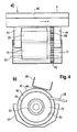
- Fig. 1 the general structure of a device for the production of flake ice is shown.
- the device comprises a trough 10 in which there is a liquid 12 to be processed into ice, typically water.
- a closable drain 14 is formed, through which the liquid 12 can be drained from the tub 10 for cleaning purposes.
- a substantially cylindrical roller 16 also referred to as Eistommel, horizontally arranged such that it partially immersed in the liquid 12.
- the shell 18 of the roll is heated by means of a cooling device 20 (explained in more detail below).
- Fig. 2 cooled down to the freezing temperature of the liquid 12 or even lower temperature.
- the low temperature of the jacket 18 causes liquid 12 to freeze on the shell 18 and forms an ice layer 22 thereon.
- the ice layer 22 is rotated by the roller 16 about its cylinder axis, in Fig. 1 in the direction indicated by the arrow 24 rotation direction, scraped off by a scraper 26 of the roller 16 and fed as Scherbeneis 28 for further use.
- FIG. 2 shows the provided for cooling the jacket 18 cooling device 20 two separate self-contained refrigerant circuits, namely on the one hand a refrigerant circuit 30 to provide the desired low temperature and on the other a refrigerant circuit 32, through which the cold generated by the refrigerant circuit 30 to the cold cold 16 is transported.
- the refrigerant circuit 30 comprises a throttle body 34, a heat exchanger 36, e.g. Plate heat exchanger, trained evaporator, a compressor 38 and a condenser 40 and thus forms a known refrigeration machine in which the circulating refrigerant between gaseous and liquid state switches back and forth.
- the refrigerant circuit 32 is coupled via the heat exchanger 36 to the refrigerant circuit 30, so that a circulating in the refrigerant circuit 32 brine, e.g. a brine, with the refrigerant of the refrigerant circuit 30 exchanges heat and thereby cooled down to the desired temperature.
- the cooled brine is pumped through the roller 16 by a pump 42 to cool the jacket 18 to the desired low temperature and to freeze the liquid 12 by removing heat from the jacket 18.
- the heat absorbed by the refrigerant during this process is then released into the refrigerant of the refrigerant circuit 30 in the heat exchanger 36, whereby the refrigerant is evaporated.
- the brine on the other hand, is always in a liquid state.
- roller 16 is rotatably mounted on two support arms 44, which in turn are suspended on a cross member 46.
- the roller 16 For rotatably supporting the roller 16 on the holding arms 44, the roller 16 has two stub axles 48, which are accommodated in corresponding bearings 50 of the holding arms 44.
- the stub axles 48 extend axially from a substantially cylindrical core 52 of the roller 16 which defines a first diameter d.
- a radially extending circumferential projection 54 is formed, which defines a second diameter D which is greater than the first diameter d.
- a circular cover plate 56 is placed such that it bears against the front side of the core 52.
- a shoulder is formed such that the lens 56 has a first peripheral surface portion 58 in which the lens 56 has the second diameter D, and also has a second peripheral surface portion 60 in which the lens 56 has a diameter greater than the second diameter D is.
- the second peripheral surface portion 60 is provided with a ring gear 62 which is engaged with a drive gear 64.
- the drive gear 64 is drivable by means of a drive motor, not shown, to enable the roller 16 in rotation.
- the offset from the axis of rotation of the roller 16, i. So decentralized, drive allows a seal-free positioning of the tub 10, whereby a disassembly of the tub 10 is greatly facilitated for cleaning purposes.
- the first peripheral surface portion 58 of the lens 56 faces the radially extending circumferential projection 54.
- the projection 54 of the core 52 surrounding shell 18 which is releasably attached to the cover plate 56 and the projection 54, for example screwed, is.
- annular gap 68 is formed, which is filled with an open-cell metal foam 70 which is penetratable by the refrigerant.
- an axially extending blind bore 72 is formed which communicates with the annular gap 68 in the region of its inner end via two radially extending radial bores 74 in opposite directions.
- the blind holes 72 communicate with refrigerant passages 76 provided in the holding arms 44.
- the refrigerant passages 76, blind holes 72, radial bores 74 and the annular gap 68 allow a flow through the roller 16 with the refrigerant carrier of circulating in the refrigerant circuit 32 the refrigerant.
- the supplied through the supply passage 78 refrigerant passes through the in Fig. 3 left blind hole 72 in the roller 16 and distributed through the in Fig. 3 left radial bores 74 in the annular gap 68, ie the in Fig. 3 left bores 72, 74 form an inlet channel 80.
- roller 16 is thus ultimately flowed through from left to right, it goes without saying that the flow direction can be reversed if necessary.
- the jacket 18 Due to the flow of the roller 16 through the refrigerant, the jacket 18 is cooled down to such a low temperature that the liquid contained in the tub 10 freezes on the outer surface of the shell 18 and there forms an ice layer 22, as already mentioned above, with Scaler 26 is scraped off the sheath 18 to form flake ice 28 when the roller 16 is rotated by the drive gear 64.
Landscapes
- Engineering & Computer Science (AREA)
- Physics & Mathematics (AREA)
- Mechanical Engineering (AREA)
- Thermal Sciences (AREA)
- General Engineering & Computer Science (AREA)
- Devices That Are Associated With Refrigeration Equipment (AREA)
- Confectionery (AREA)
Applications Claiming Priority (1)
| Application Number | Priority Date | Filing Date | Title |
|---|---|---|---|
| DE102011017038A DE102011017038A1 (de) | 2011-04-14 | 2011-04-14 | Vorrichtung zur Erzeugung von Scherbeneis |
Publications (1)
| Publication Number | Publication Date |
|---|---|
| EP2511631A2 true EP2511631A2 (fr) | 2012-10-17 |
Family
ID=46045785
Family Applications (1)
| Application Number | Title | Priority Date | Filing Date |
|---|---|---|---|
| EP12164053A Withdrawn EP2511631A2 (fr) | 2011-04-14 | 2012-04-13 | Dispositif destiné à la génération de glace en copeaux |
Country Status (3)
| Country | Link |
|---|---|
| US (1) | US20130192290A1 (fr) |
| EP (1) | EP2511631A2 (fr) |
| DE (1) | DE102011017038A1 (fr) |
Families Citing this family (3)
| Publication number | Priority date | Publication date | Assignee | Title |
|---|---|---|---|---|
| CN104101147A (zh) * | 2014-05-14 | 2014-10-15 | 广州中臣碧阳船舶科技有限公司 | 一种卧式海水片冰发生器 |
| KR101900697B1 (ko) * | 2017-06-16 | 2018-11-05 | 코리아나까조 주식회사 | 원료수 공급모듈을 이용한 연속 설빙방법 및 이를 이용한 설빙기 |
| KR102087581B1 (ko) * | 2019-10-22 | 2020-03-11 | 김진희 | 얼음 맥주용 얼음 가공 장치 및 얼음 맥주 제조 방법 |
Family Cites Families (19)
| Publication number | Priority date | Publication date | Assignee | Title |
|---|---|---|---|---|
| US2749722A (en) * | 1952-09-19 | 1956-06-12 | Frank W Knowles | Apparatus for making ice in small pieces |
| US2763996A (en) * | 1953-01-28 | 1956-09-25 | Gerald M Lees | Ice making machine and method of hydraulically harvesting ice |
| CH504657A (de) * | 1966-12-14 | 1971-03-15 | Schill Maja Masch | Vorrichtung zur Erzeugung von Feineis od. dgl. Gefrierprodukten |
| US3869870A (en) * | 1973-07-02 | 1975-03-11 | Borg Warner | Refrigeration system utilizing ice slurries |
| US4538428A (en) * | 1984-04-02 | 1985-09-03 | Wilkerson Kenneth L | Ice-making machine |
| DE9101195U1 (de) * | 1991-02-02 | 1991-04-25 | Maja-Maschinenfabrik Hermann Schill Gmbh, 7640 Kehl | Vorrichtung zum Herstellen und Ablösen von Feineis aus Wasser o.dgl. |
| US5307646A (en) * | 1991-06-25 | 1994-05-03 | North Star Ice Equipment Corporation | Flake ice machine |
| US5431027A (en) * | 1992-03-23 | 1995-07-11 | Henry Vogt Machine Co. | Flake ice-making apparatus |
| WO1995024596A1 (fr) * | 1994-03-09 | 1995-09-14 | Maja Maschinenfabrik Hermann Schill Gmbh | Machine automatique pour la production de glace en flocons |
| US5448894A (en) * | 1994-09-21 | 1995-09-12 | North Star Ice Equipment Corporation | Disk flake ice machine |
| US5632159A (en) * | 1996-03-29 | 1997-05-27 | North Star Ice Equipment Corporation | Cooling disk for flake ice machine |
| JP3683384B2 (ja) * | 1997-07-07 | 2005-08-17 | ホシザキ電機株式会社 | オーガ式製氷機 |
| IL131518A (en) * | 1999-08-22 | 2006-06-11 | Fluid Ice Systems Ltd | Method and device for continuous production of ice-solution suspension |
| DE10017723A1 (de) * | 2000-04-11 | 2001-10-18 | Schill Maja Masch | Scherbeneismaschine |
| AU2003260285A1 (en) * | 2002-09-11 | 2004-04-30 | Flaga Ice V/Jensen, Bian | Apparatus for producing ice flakes |
| US7788934B2 (en) * | 2003-10-31 | 2010-09-07 | Hoshizaki Denki Kabushiki Kaisha | Control device for an auger type ice making machine |
| DE102005039989A1 (de) * | 2004-08-26 | 2006-03-02 | Hartmut Higel | Vorrichtung zum Herstellen von Scherbeneis |
| US7266969B2 (en) * | 2005-01-06 | 2007-09-11 | Ut-Batelle, Llc | Refrigerant directly cooled capacitors |
| CN101957112B (zh) * | 2009-07-14 | 2012-08-29 | 江苏白雪电器股份有限公司 | 制冰装置 |
-
2011
- 2011-04-14 DE DE102011017038A patent/DE102011017038A1/de not_active Withdrawn
-
2012
- 2012-04-12 US US13/445,411 patent/US20130192290A1/en not_active Abandoned
- 2012-04-13 EP EP12164053A patent/EP2511631A2/fr not_active Withdrawn
Non-Patent Citations (1)
| Title |
|---|
| None |
Also Published As
| Publication number | Publication date |
|---|---|
| US20130192290A1 (en) | 2013-08-01 |
| DE102011017038A1 (de) | 2012-10-18 |
Similar Documents
| Publication | Publication Date | Title |
|---|---|---|
| DE102014107294B4 (de) | Zentrifuge | |
| EP0166807B1 (fr) | Pompe à vide rotative à palettes | |
| DE102011017038A1 (de) | Vorrichtung zur Erzeugung von Scherbeneis | |
| EP2406564B1 (fr) | Dispositif pour produire de la glace en flocons | |
| DE2422863A1 (de) | Vorrichtung zur kontinuierlichen eiserzeugung | |
| DE1428074A1 (de) | Kompressor fuer Entsalzungssystem | |
| DE102017004213A1 (de) | Verfahren und Anlage zur Steuerung und/oder Regelung der Behandlung hitzeempfindlicher flüssiger Nahrungsmittelprodukte | |
| EP0472541B1 (fr) | Arrangement de coussinet avec dispositif de refoulement automatique de lubrifiant | |
| EP3994359B1 (fr) | Dispositif de pompe | |
| EP3452765B1 (fr) | Dispositif pour la production de glace, en particulier de glace en copeaux | |
| DE102016008558A1 (de) | Verfahren und Anlage zur Behandlung hitzeempfindlicher flüssiger Nahrungsmittelprodukte und Zentrifugalpumpe für eine solche Anlage | |
| WO2013045060A1 (fr) | Dispositif de fixation pour boîtier d'extrudeuse | |
| DE102007036213A1 (de) | Pumpe | |
| EP2902629A1 (fr) | Pompe à vide avec réfrigérateur de lubrifiant | |
| DE102005033676A1 (de) | Getriebeschmiersystem zum Abschleppen und Verfahren dafür | |
| DE10221523A1 (de) | Vorrichtung zur Herstellung von Scherbeneis | |
| DE630904C (de) | Verfahren und Vorrichtung zum Behandeln von Fluessigkeiten in der Waerme bzw. kaelte | |
| DE102010048697B4 (de) | Mischverfahren und Kühlmischer | |
| EP1454101B1 (fr) | Dispositif de fabrication de glace en flocons | |
| DE3300013A1 (de) | Vorrichtung und vefahren zum herstellen von scherbeneis | |
| AT14090U1 (de) | Primärer Fermentationstank mit einer mechanischen Kühl- und/ oder Entgasungseinrichtung | |
| DE19822228B4 (de) | Scherbeneismaschine | |
| DE461271C (de) | Fluessigkeitsringpumpe | |
| DE19507864A1 (de) | Scherbeneisautomat | |
| DE102008022175A1 (de) | Vorrichtung zur Erzeugung von Scherbeneis |
Legal Events
| Date | Code | Title | Description |
|---|---|---|---|
| PUAI | Public reference made under article 153(3) epc to a published international application that has entered the european phase |
Free format text: ORIGINAL CODE: 0009012 |
|
| AK | Designated contracting states |
Kind code of ref document: A2 Designated state(s): AL AT BE BG CH CY CZ DE DK EE ES FI FR GB GR HR HU IE IS IT LI LT LU LV MC MK MT NL NO PL PT RO RS SE SI SK SM TR |
|
| AX | Request for extension of the european patent |
Extension state: BA ME |
|
| RIN1 | Information on inventor provided before grant (corrected) |
Inventor name: DIE ERFINDER HABEN AUF IHRE NENNUNG VERZICHTET. |
|
| STAA | Information on the status of an ep patent application or granted ep patent |
Free format text: STATUS: THE APPLICATION IS DEEMED TO BE WITHDRAWN |
|
| 18D | Application deemed to be withdrawn |
Effective date: 20151103 |