EP3452765B1 - Dispositif pour la production de glace, en particulier de glace en copeaux - Google Patents
Dispositif pour la production de glace, en particulier de glace en copeaux Download PDFInfo
- Publication number
- EP3452765B1 EP3452765B1 EP17733344.0A EP17733344A EP3452765B1 EP 3452765 B1 EP3452765 B1 EP 3452765B1 EP 17733344 A EP17733344 A EP 17733344A EP 3452765 B1 EP3452765 B1 EP 3452765B1
- Authority
- EP
- European Patent Office
- Prior art keywords
- refrigerant
- drum
- ice
- ice drum
- evaporator
- Prior art date
- Legal status (The legal status is an assumption and is not a legal conclusion. Google has not performed a legal analysis and makes no representation as to the accuracy of the status listed.)
- Active
Links
Images



Classifications
-
- F—MECHANICAL ENGINEERING; LIGHTING; HEATING; WEAPONS; BLASTING
- F25—REFRIGERATION OR COOLING; COMBINED HEATING AND REFRIGERATION SYSTEMS; HEAT PUMP SYSTEMS; MANUFACTURE OR STORAGE OF ICE; LIQUEFACTION SOLIDIFICATION OF GASES
- F25C—PRODUCING, WORKING OR HANDLING ICE
- F25C1/00—Producing ice
- F25C1/12—Producing ice by freezing water on cooled surfaces, e.g. to form slabs
- F25C1/14—Producing ice by freezing water on cooled surfaces, e.g. to form slabs to form thin sheets which are removed by scraping or wedging, e.g. in the form of flakes
- F25C1/142—Producing ice by freezing water on cooled surfaces, e.g. to form slabs to form thin sheets which are removed by scraping or wedging, e.g. in the form of flakes from the outer walls of cooled bodies
-
- F—MECHANICAL ENGINEERING; LIGHTING; HEATING; WEAPONS; BLASTING
- F25—REFRIGERATION OR COOLING; COMBINED HEATING AND REFRIGERATION SYSTEMS; HEAT PUMP SYSTEMS; MANUFACTURE OR STORAGE OF ICE; LIQUEFACTION SOLIDIFICATION OF GASES
- F25C—PRODUCING, WORKING OR HANDLING ICE
- F25C2305/00—Special arrangements or features for working or handling ice
- F25C2305/022—Harvesting ice including rotating or tilting or pivoting of a mould or tray
Definitions
- the invention is based on a device for producing ice, in particular flake ice from a liquid, with a rotatably arranged cylindrical ice drum, a liquid application device with which a liquid to be frozen is applied to the ice drum, and a scraper for removing material formed on the surface of the ice drum Ice and an evaporator arranged within the ice drum, in which a refrigerant is evaporated.
- Such devices are used to produce ice crystals from liquids, especially water.
- thin sheets, small grains, granules, snow or flakes are formed from the ice crystals.
- the ice is called flake ice.
- the flake ice is used, for example, in the food industry to produce food and to keep food fresh during transport and storage. In this way, for example, meat, fish or seafood can be stored and transported without their quality suffering.
- flake ice is used in the production of sausage.
- other liquids such as juices, sauces, eggs, milk and dairy products can also be processed into flake ice.
- the flake ice made from different liquids is used in medicine, pharmacy and technology.
- a device for producing flake ice in which a cylindrical evaporator is rotatably mounted in a trough that holds the liquid to be frozen and is rotated by a drive Longitudinal axis is rotated.
- the cylindrical evaporator is also called an evaporator roller.
- refrigerant channels run in the form of a helix along the inward-facing side of the jacket of the evaporator roller.
- the refrigerant is supplied to the refrigerant channels running in the evaporator roller via a refrigerant supply and is drained from the evaporator roller via a refrigerant drain.
- the DE 91 16 102 U1 discloses a device for the continuous production of writing ice with a trough that holds the liquid to be frozen, a motor-driven, cylindrical ice drum mounted in the trough so as to be rotatable about a horizontal axis and a fixed coil evaporator arranged within the ice drum.
- the coil evaporator has a copper tube that forms the refrigerant channel and runs in the form of a helix around the horizontal axis. Each turn forms a depression at its lowest level in which lubricants can settle. This applies in particular if the refrigerant has evaporated to a certain extent and has therefore predominantly passed into the vapor phase or if the rate of spread of the refrigerant is low.
- the US 2,724,949 A discloses a flake ice machine with a fixed evaporator which is surrounded by an ice drum driven to rotate.
- the evaporator is designed as a cylindrical evaporator chamber.
- the ice drum is arranged in a water tank. In the space between An annular plate with a scraper is arranged in the water tank and the ice drum, which removes the ice that forms on the surface of the ice drum.
- the evaporator is equipped with a refrigerant supply and a gas outlet pipe for the evaporated refrigerant.
- the refrigerant supply opens into a pipe, which serves as a filler neck for introducing the refrigerant into the evaporator chamber.
- the refrigerant flowing out of the pipe distributes freely in the evaporator and evaporates.
- the evaporated refrigerant escapes from the evaporator via the gas outlet pipe, which opens into an end face of the evaporator chamber.
- the US 3,762,181 A discloses a device for producing ice on a conveyor belt that is guided over several drum units.
- a drum unit is designed as a hot gas drum unit.
- the remaining drum units are each equipped with an outer rotatable transfer drum and a fixed inner drum, which is designed as a cylindrical evaporator chamber.
- the space between the outer and inner drum is filled with a liquid, which is intended to additionally support the cold transfer.
- the inner drum has several plates arranged in parallel with holes for separating oil and refrigerant.
- the inner drum is connected at its end faces to an inlet pipe and an outlet pipe for the refrigerant.
- the gaseous refrigerant is removed from the inner drum via a suction pipe and fed to a storage tank.
- Another tube is used to extract oil from the bottom of the inner drum.
- water is applied to the endless belt, which freezes on the belt due to the cooled drum units. If the ice on the belt reaches the hot gas drum unit, the ice comes off the belt and is collected by a collecting container.
- the device proves to be disadvantageous DE 91 16 102 U1 , US 2,724,949 A and US 3,762,181 A that lubricants carried by the refrigerant can settle in the evaporator so that they are useful for the Lubrication of the device is no longer available and affects the cooling.
- the invention is therefore based on the object of providing a device for producing ice, in particular flake ice, in which rotary feedthroughs on the refrigerant supply and on the refrigerant discharge can be dispensed with, in which the settling of lubricants is significantly reduced Scope in the refrigerant channel of the evaporator is avoided, and with the flake ice can be produced in good quality and in compliance with the high hygiene and purity requirements in the food sector.
- the device according to the invention according to claim 1 is characterized in that it is equipped with an ice drum which is rotatably arranged and driven to rotate by a drum drive and which is hollow on the inside.
- An evaporator is arranged in a stationary manner in the interior of the ice cream drum. It doesn't rotate with the ice cream drum.
- the evaporator has a refrigerant supply, a refrigerant discharge and at least one refrigerant channel connecting the refrigerant supply and the refrigerant discharge, through which a refrigerant flows in the direction of propagation and evaporates in the process.
- the level of the refrigerant channel changes continuously or gradually in the same direction from the refrigerant supply to the refrigerant discharge.
- a coolant in the space between the evaporator and the surface of the ice drum facing the interior ensures that the cold from the evaporator is transferred to the ice drum.
- the refrigerant channel does not run in the form of a helix on the inward-facing side of the ice drum, but rather in such a way that either the level of the refrigerant channel in the direction of propagation of the refrigerant from the refrigerant supply to the refrigerant discharge remains essentially the same or with a Level change is always in the same direction.
- the increase or decrease in the level can occur continuously, i.e. steadily, or gradually.
- the refrigerant supply and the refrigerant discharge are connected to the refrigeration circuit of a refrigeration machine.
- the refrigerant circulating in the refrigeration circuit always contains a certain proportion of lubricants, which are necessary for some components of the refrigeration machine. These lubricants do not affect the refrigeration circuit as long as they are carried by the refrigerant and do not settle in one or more places in the refrigeration circuit. This also applies to the refrigerant channel in the evaporator.
- a refrigerant channel with the shape of a helix like that DE 195 07 864 A1 is possible with an evaporator driven to rotate.
- each turn forms a depression at its lowest level in which lubricants can settle.
- the refrigerant has evaporated to a certain extent and has therefore predominantly passed into the vapor phase or if the rate of spread of the refrigerant is low. If the lubricants settle in the refrigerant channel of the evaporator, this leads to an undesirable reduction in the cooling capacity of the evaporator. In addition, the lubricants no longer circulate in the refrigeration circuit and are therefore missing from another part of the refrigeration circuit.
- the refrigerant channel according to claim 1 is free of sinks.
- the course of the refrigerant channel according to the invention has the advantage that no lubricants can settle in the refrigerant channel.
- the performance of the evaporator can therefore be maintained over a long period of time. It has been shown that small level differences in the refrigerant channel of the evaporator do not lead to the lubricants settling. This is particularly true if the refrigerant is predominantly in the liquid phase or the refrigerant has a high flow rate.
- the level of the refrigerant channel decreases essentially continuously or gradually in the direction of propagation of the refrigerant from the refrigerant supply to the refrigerant discharge.
- the level of the refrigerant channel increases essentially continuously or stepwise in the direction of propagation of the refrigerant from the refrigerant supply to the refrigerant discharge.
- the refrigerant channel has a plurality of first sections which run essentially parallel to the axis of rotation of the ice cream drum.
- the first sections preferably have a straight course.
- the refrigerant channel has a plurality of second sections, with each second section connecting two first sections of the refrigerant channel that follow each other in the direction of propagation of the refrigerant.
- the second sections can be curved sections, for example.
- the refrigerant channel from the refrigerant supply runs essentially only once parallel to the axis of rotation of the ice drum through the evaporator before it opens into the refrigerant discharge line. This course is sufficient for small ice cream drums with a correspondingly small evaporator.
- the refrigerant channel runs in one or more levels.
- the at least one level can be aligned horizontally.
- the at least one plane may be inclined to the horizontal, typically at an angle of less than 10°. If the refrigerant channel runs in several levels, these levels can be aligned parallel to one another. If several refrigerant channels are provided, each refrigerant channel can run on a separate level.
- the refrigerant channel is guided back and forth within the level. It can have several mutually parallel sections in the plane, which run parallel to the axis of rotation of the ice cream drum or perpendicular to the axis of rotation or perpendicular to a parallel to the axis of rotation or under any other orientation.
- the parallel sections of the refrigerant channel in the plane are connected to one another by curved connecting sections.
- the cross-sectional area of the refrigerant channel or channels increases in the direction of propagation of the refrigerant.
- This increases the flow cross section of the refrigerant in the direction of propagation. This can be achieved, for example, by the refrigerant channel becoming continuously or gradually wider in the direction of propagation or by dividing a refrigerant channel into several sections. Due to the increase in volume when the refrigerant transitions from the liquid to the vapor state, the cross-sectional area of the refrigerant channel changes flow velocity.
- the flow velocity can be kept at least approximately constant. Alternatively, the increase in flow velocity can be reduced.
- the flow cross section of the refrigerant channel or channels thus influences the flow dynamics, the thermodynamics, the pressure loss and thus the cooling capacity of the evaporator to be transferred.
- the refrigerant channel is formed by a tube.
- the tube can have a circular, other round, for example oval, or an angular cross-section.
- the tube has a surface-enlarging structure on its outside.
- the tube can, for example, be equipped on its outside with grooves, with a corrugation, a cross corrugation or a pyramid structure.
- additional elements such as slats can be provided on the tube.
- the slats can have a circular, spiral, arbitrarily curved or straight path.
- the refrigerant channel is formed by an extruded profile with a micro or mini channel.
- the micro or mini channel forms a channel in the extruded profile through which the refrigerant flows.
- the device is equipped with a circulation device for the coolant. This ensures that the coolant is set in motion. This improves the cold transfer from the evaporator to the ice drum.
- the circulating device has an agitator with at least one agitator shaft driven to rotate and agitator blades arranged on the agitator shaft.
- the agitator shaft extends inside the ice cream drum preferably parallel or essentially parallel to the axis of rotation of the ice cream drum. It can also be arranged coaxially to the axis of rotation of the ice cream drum.
- the agitator shaft can also be arranged at an angle greater than 0° relative to the axis of rotation of the ice cream drum.
- cup-like stirring elements can also be arranged on the stirring shaft.
- the stirring shaft is connected to a stirring drive. This is preferably arranged outside the ice cream drum.
- At least one impact body is arranged on the agitator shaft. It ensures that the coolant is directed towards the inside of the ice cream drum.
- the impact body can have a conical shape, for example. It is arranged on the agitator shaft in such a way that the axis of the cone extends along the axis of the agitator shaft.
- At least one coolant volume limiting device is arranged in the ice drum. This ensures that the coolant does not fill the entire volume of the interior of the ice drum minus the evaporator, but only a part of this volume.
- the coolant volume limiting device can be, for example, a displacement body which is arranged in the ice drum next to the evaporator.
- a chamber can be separated within the ice drum into which the coolant cannot flow.
- the ice cream drum has a drum shell and, on each of the two end faces of the drum shell, a side part which is sealingly connected to the drum shell.
- One of the two side parts is directly or indirectly coupled to the drum drive.
- the device is equipped with a fixed axle or fixed axle stubs, which run coaxially to the axis of rotation of the ice cream drum.
- the ice drum is rotatably mounted on this fixed axle or these fixed axle stubs. At least a section of the coolant supply and a section of the coolant discharge run through the fixed axle or the axle stubs.
- the device for producing ice, in particular flake ice can be filled with a refrigerant without additional aids, such as pumps, and the refrigerant can be completely removed from the ice drum without additional aids.
- the device is equipped with an air line which connects the interior of the ice drum with the surroundings of the ice drum. The interior of the ice cream drum can be ventilated and vented via this air line.
- the device is equipped with a refrigerant line, via which a refrigerant can be filled into the interior of the ice drum and drained from the interior of the ice drum. Venting is important in order to fill the ice drum with coolant.
- the air line is arranged in a fixed manner. This means that it does not rotate with the ice cream drum and always remains in the same orientation.
- the air line has a first section which is parallel to the axis of rotation of the ice cream drum runs. Furthermore, the air line has a second section which runs in the interior of the ice cream drum essentially radially to the axis of rotation of the ice cream drum. The first section can run through a fixed axis of the ice drum.
- the air line extends to a surface of the jacket of the ice cream drum that faces the interior.
- the distance between an open end of the air duct facing the inside of the ice drum on the one hand and the inside of the ice drum on the other hand is so large that air can flow into the open end of the air duct and air can flow out of the end.
- the air line therefore does not touch the inside of the ice cream drum with its open end.
- the air line opens into the interior of the ice drum near the inside of the jacket of the ice drum and on the upward-facing side of the ice drum.
- the air line is preferably aligned essentially vertically upwards, so that the open end of the air line, at which the air flows from the ice cream drum into the air line and at which the air flows out of the air line into the ice cream drum, is arranged near the highest level of the ice cream drum is.
- the coolant line has a first section which runs parallel to the axis of rotation of the ice cream drum. Furthermore, the coolant line has a second section which runs radially in the interior of the ice cream drum to the axis of rotation of the ice cream drum. The first section can extend through a fixed axis of the ice drum.
- the coolant line is arranged in a fixed manner. This means that it does not rotate with the ice cream drum.
- the second section of the coolant line extends to the inside of the jacket of the ice drum.
- the distance between an open end of the refrigerant line facing the inside of the ice drum on the one hand and the inside of the ice drum on the other hand is so large that refrigerant can flow into the open end of the refrigerant line and refrigerant can flow out of the end.
- the coolant line therefore does not touch the inside of the ice drum with its open end.
- the coolant line opens into the interior of the ice drum near the inside of the jacket and on the downward-facing side of the ice drum. This ensures that the coolant can be completely drained from the cold drum.
- the coolant line can run vertically. The course of the coolant line can be straight or curved.
- the device is equipped with a coolant expansion tank which is fixedly arranged outside the ice drum and which is connected to the interior of the ice drum via the coolant line.
- the coolant expansion tank is filled with coolant and connected to the interior of the ice drum via the coolant line.
- the coolant expansion tank is not sealed against the atmosphere. It is an open system. In the event of pressure and volume fluctuations in the interior of the ice drum, which are triggered by temperature fluctuations, coolant is fed from the coolant expansion tank into the ice drum or from the ice drum, coolant is fed into the coolant expansion tank. In this way the pressure is equalized.
- the coolant expansion tank has a lowest level and a highest level.
- the lowest level is below the ice drum and the highest level is above the ice drum.
- the first section of the coolant line is connected to the lowest level of the coolant expansion tank via a pipe in the coolant expansion tank. The highest and lowest levels above and below the ice drum ensure that the coolant can be filled into the ice drum and drained out of the ice drum.
- the air line can be closed airtight at its end facing the environment.
- the coolant line can be closed airtight and liquid-tight at its end facing the environment.
- the device is equipped with a volume compensation container within the ice drum, which compensates for volume expansion and volume compression of the refrigerant due to temperature fluctuations.
- the volume compensation container contracts when the pressure in the ice drum increases and expands when the pressure in the ice drum decreases.
- the air line and the coolant line are sealed against the atmosphere when closed. It is a closed system.
- Known devices for producing flake ice have the disadvantage that the jacket and the side parts of the ice drum are connected to one another via screws or pins. These screws or pins are incorporated into the side parts of the ice cream drum via the outside of the casing so that the face of the screws or pins is flush with the casing.
- the disadvantage is that the end faces of the screws or pins on the outside of the jacket of the ice drum come into contact with the liquid to be frozen. This is disadvantageous in terms of hygiene.
- screws or pins can come loose and end up in the liquid to be frozen.
- the shell of the ice drum must have a certain wall thickness so that the screws or pins can be attached at all.
- the ice cream drum has a drum shell and two side parts, which are arranged on the end faces of the drum shell.
- the side parts are detachably connected to the drum shell via a clamping device.
- the clamping device is first inserted into the drum shell and fixed at a predetermined position. Then the two side parts are placed on the front sides of the drum shell and connected to the clamping devices. This can be done using screws, for example. The screws are inserted into the clamping device via the side parts.
- the drum shell is equipped with grooves on the inside.
- the clamping device engages in the grooves with outwardly projecting projections and can be fixed to the drum shell.
- Each of the two side parts can be attached to a clamping device.
- the side parts are equipped with seals on the circumference, which make a sealing contact with the drum casing. Once the side parts have been removed from the drum shell, the seals can be replaced if necessary.
- the side parts are equipped with a bearing bushing, via which the ice cream drum is rotatably mounted on a fixed axis.
- a housing for a device for producing ice, in particular flake ice meets high hygiene requirements.
- the device is equipped with a housing that covers the ice drum, the evaporator, the liquid application device and the scraper at the top and on the sides.
- the upward-facing parts of the housing are inclined towards the horizontal so that they form an inclined plane. The result of this is that a liquid that differs from the liquid to be frozen and which accumulates on the surface of the housing can flow away following its weight. This means it does not get into the liquid to be frozen. Contamination of the housing is also excluded or at least minimized.
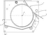
- Figure 1 is a device for producing ice according to claim 1, in particular flake ice with an ice drum 1, which is driven to rotate about an axis of rotation 2, and a trough serving as a liquid application device 3.
- the ice drum is partially immersed in a liquid to be frozen, which is filled into the tub.
- a stationary scraper 4 serves to remove the ice formed from the liquid on the surface of the ice drum in the form of flake ice.
- the flake ice is transported away via a slide 5.
- An evaporator 6 is arranged in a stationary manner in the ice cream drum 1.
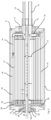
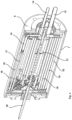
- the evaporator is in the Figures 2 , 3 and 4 shown.
- the ice cream drum has a drum shell 7 and side parts 8 and 9.
- a rotary drive, not shown in the drawing, is coupled to the side part 8.
- the two side parts 8 and 9 point a through opening, in each of which a bearing bush 10, 11 is accommodated.
- the bearing bushes are arranged on fixed axle stubs 12, 13.
- a refrigerant supply 14 and a refrigerant discharge line 15 are passed through the fixed axle stub 13.
- the refrigerant supply 14 and the refrigerant discharge line 15 are connected to a refrigerant circuit, of which only the evaporator 6 is shown in the drawing.
- a refrigerant is supplied to the evaporator 6 via the refrigerant supply 14.
- the coolant supply 14 opens at the in Figure 4 evaporator 6 shown in a total of four refrigerant channels. There in the Figure 4 Only one half of the evaporator 6 is shown, only two refrigerant channels 16, 17 of these four refrigerant channels can be seen.
- a first section of the refrigerant channel 16 extends from the refrigerant supply 14 to a distributor 16a. The first section of the refrigerant channel 16 merges into two second sections 16b and 16c via the distributor 16a. This increases the flow cross section through which the refrigerant flows in the direction of propagation.
- the first section of the refrigerant channel 17 merges into two second sections 17b and 17c via a distributor 17a.
- the sections 16b, 16c, 17b and 17c of the two refrigerant channels 16 and 17 open into a pot 15a of the refrigerant drain 15.
- the refrigerant channels of the evaporator 6 have eight sections that open into the pot 15a of the refrigerant discharge line. The refrigerant flows through the refrigerant channels from the refrigerant supply 14 to the refrigerant discharge 15 and is evaporated in the process.
- a coolant is arranged, which transfers the cold from the evaporator 6 to the ice cream drum 1.
- the refrigerant channels 16, 17 have a plurality of straight first sections 18 and a plurality of curved second sections 19.
- the first sections 18 run essentially parallel to the axis of rotation 2 of the ice cream drum 1. Every second section 19 connects two first sections 18 of the refrigerant channel 16, 17 which follow one another in the direction of propagation of the refrigerant.
- the level of the refrigerant channels 16, 17 is highest at the refrigerant supply 14 and lowest at the refrigerant discharge line 15. In between, the level of the two refrigerant channels 16, 17 drops gradually. Lubricants dissolved or otherwise contained in the liquid refrigerant cannot settle if the refrigerant channel runs in this way.
- a circulating device with a stirrer shaft 20 and stirrer blades 21 is arranged in the interior of the ice cream drum 1.
- the stirrer shaft is connected to a stirrer drive, not shown in the drawing.
- a coolant line 23 with its first section 24 is passed through the fixed axle stub 12.
- the first section 24 runs parallel to the axis of rotation 2 of the ice cream drum 1.
- a second section 25 of the coolant line 23 runs in the interior of the ice drum 1 radially to the axis of rotation 2 of the ice cream drum 1. It extends close to the surface facing the interior the ice drum 1 to the lowest level.
- An air line 26 with its first section 27 is guided through the fixed axle stub 12.
- the first section 27 runs parallel to the axis of rotation 2 of the ice cream drum 1.
- a second section 28 of the air line 26 runs in the interior of the ice cream drum 1 radially to the axis of rotation 2 of the ice cream drum 1. It extends into the vicinity of the surface of the ice cream drum facing the interior 1 to a highest level.
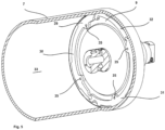
- the Figures 5 and 6 show the attachment of the side part 9 to the drum shell 7 by means of a clamping device 29.
- the clamping device 29 has three clamping parts 30, 31, 32 which are connected to one another. Each of the clamping parts 30, 31, 32 has projections that protrude outwards and cannot be seen in the drawing.
- the drum shell 7 is equipped with grooves 34 on its inside 33.
- the clamping device 29 is arranged in the drum shell 7 in such a way that the projections are accommodated in the grooves 34.
- the side part 9 is then attached to the clamping device 29.
- the clamping device has several threaded holes 35.
- the side part has through openings 36, which can also be equipped with a thread. Screws are inserted into the through openings 36 and the threaded holes 35 and tightened.
- the side part 9 is clamped to the drum shell 7.
- the Figures 7 and 8th show a coolant expansion tank 37, which is connected to the coolant line 23.
- the coolant expansion tank 37 has a lowest level 38 below the ice drum 1 and a highest level 39 above the ice drum 1.
- the coolant line is connected via a pipe 40 to the lowest level 38 of the coolant expansion tank.
- the pipe 40 connects directly to the first section 24 of the coolant line 23.
- a closable opening 41 is provided on the coolant expansion tank 37, via which a coolant can be drained from the coolant expansion tank 37.
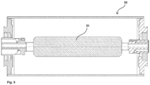
- FIG 9 a second embodiment of an ice cream drum 50 is shown.
- a volume compensation container 51 with which volume and pressure fluctuations can be compensated for.
- the volume compensation container 51 is arranged in the interior of the ice cream drum 50. When the pressure in the ice cream drum increases, the volume compensation container is compressed. When the pressure is reduced, the volume expansion tank 51 expands.
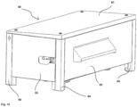
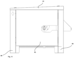
- the Figures 10 and 11 show a housing 60 with a cover 61, a front cover 62, a side cover 63 and feet 64.
- the rear cover and a second side cover are not in the drawing recognizable.
- the lid 61 is equipped with an inclined plane through which liquids can flow away.
Landscapes
- Engineering & Computer Science (AREA)
- Physics & Mathematics (AREA)
- Mechanical Engineering (AREA)
- Thermal Sciences (AREA)
- General Engineering & Computer Science (AREA)
- Confectionery (AREA)
Claims (30)
- Dispositif pour la production de glace, en particulier de glace en copeaux à partir d'un liquide,avec un tambour à glace cylindrique (1, 50) disposé de manière à pouvoir tourner et entraîné en rotation autour d'un axe de rotation (2) par un entraînement de tambour,avec un dispositif d'application de liquide (3) qui applique le liquide à congeler à la surface du tambour à glace (1, 50),avec un grattoir (4) pour enlever la glace formée à partir du liquide à la surface du tambour à glace (1, 50),avec un évaporateur (6) fixe disposé à l'intérieur du tambour à glace (1, 50), dans lequel un fluide frigorigène est évaporé,avec une entrée de fluide frigorigène (14) qui alimente l'évaporateur (6) en fluide frigorigène,avec une sortie de fluide frigorigène (15) qui évacue le fluide frigorigène de l'évaporateur (6),avec un fluide frigoporteur entre l'évaporateur (6) et le tambour à glace (1, 50) qui transmet le froid de l'évaporateur (6) au tambour à glace (1, 50), ledit tambour étant équipé d'un moins un conduit de fluide frigorigène (16, 17) de l'évaporateur (6) reliant l'entrée de fluide frigorigène (14) à la sortie de fluide frigorigène (15) et dans lequel circule le fluide frigorigène dans le sens de propagation,caractérisé en ce quele niveau du conduit de fluide frigorigène (16, 17), dans le sens de propagation du fluide frigorigène (16, 17) entre l'entrée de fluide frigorigène (14) et la sortie de fluide frigorigène (15), reste essentiellement constant ou change de façon continue ou par étapes toujours dans le même sens, et en ce que le conduit de fluide frigorigène (16, 17) entre l'entrée de fluide frigorigène (14) et la sortie de fluide frigorigène (15) est dépourvu de spires formant un creux à leur niveau le plus bas et dans lequel les lubrifiants se déposent.
- Dispositif selon la revendication 1, caractérisé en ce que le niveau du conduit de fluide frigorigène (16, 17) reste essentiellement constant ou diminue de façon continue ou par étapes dans le sens de propagation du fluide frigorigène entre l'entrée de fluide frigorigène (14) et la sortie de fluide frigorigène (15).
- Dispositif selon la revendication 1, caractérisé en ce que le niveau du conduit de fluide frigorigène (16, 17) reste essentiellement constant ou augmente de façon continue ou par étapes dans le sens de propagation du fluide frigorigène entre l'entrée de fluide frigorigène (14) et la sortie de fluide frigorigène (15).
- Dispositif selon l'une quelconque des revendications précédentes, caractérisé en ce que le conduit de fluide frigorigène (16, 17) présente plusieurs premiers tronçons (18) essentiellement parallèles à l'axe de rotation (2) du tambour à glace (1, 50), et en ce que le conduit de fluide frigorigène (16, 17) présente plusieurs deuxièmes tronçons (19), chaque deuxième tronçon (19) reliant entre eux deux premiers tronçons (18) du conduit de fluide frigorigène (16, 17) qui se succèdent dans le sens de propagation du fluide frigorigène.
- Dispositif selon l'une quelconque des revendications 1 à 3, caractérisé en ce que le conduit de fluide frigorigène est essentiellement parallèle à l'axe de rotation (2) du tambour à glace (1, 50).
- Dispositif selon l'une quelconque des revendications précédentes, caractérisé en ce que l'aire de la section du conduit de fluide frigorigène (16, 17) ou des conduits de fluide frigorigène augmente dans le sens de propagation du fluide frigorigène.
- Dispositif selon l'une quelconque des revendications précédentes, caractérisé en ce que le conduit de fluide frigorigène (16, 17) est un tube.
- Dispositif selon la revendication 7, caractérisé en ce que le tube présente, sur sa face extérieure, une structure augmentant sa surface.
- Dispositif selon l'une quelconque des revendications 1 à 6, caractérisé en ce que le conduit de fluide frigorigène est un profilé extrudé pourvu de micro-canaux ou de mini-canaux.
- Dispositif selon l'une quelconque des revendications précédentes, caractérisé en ce qu'il est équipé d'un dispositif de circulation du fluide frigoporteur.
- Dispositif selon la revendication 10, caractérisé en ce que ledit dispositif de circulation comprend un agitateur comportant au moins un arbre agitateur (20) entraîné en rotation et des palettes agitatrices (21) disposées au niveau de l'arbre agitateur (20).
- Dispositif selon la revendication 10 ou 11, caractérisé en ce que au moins un déflecteur est disposé au niveau de l'arbre agitateur (20).
- Dispositif selon l'une quelconque des revendications précédentes, caractérisé en ce que le tambour à glace (1, 50) présente une enveloppe de tambour (7) et une partie latérale (8, 9) reliée à l'enveloppe de tambour (7) de manière étanche au niveau de chacune des deux faces d'extrémité de l'enveloppe de tambour (7), et en ce que une des deux parties latérales (8, 9) est couplée indirectement ou directement à l'entraînement de tambour.
- Dispositif selon l'une quelconque des revendications précédentes, caractérisé en ce qu'il est équipé d'un arbre fixe ou de tourillons fixes (12, 13) coaxiaux à l'axe de rotation (2) du tambour à glace (1, 50) et sur lesquels le tambour à glace (1, 50) est logé de façon à pouvoir tourner, et en ce qu'au moins un tronçon de l'entrée de fluide frigorigène (14) et un tronçon de la sortie de fluide frigorigène (15) passent par l'arbre fixe ou les tourillons fixes (12, 13).
- Dispositif selon l'une quelconque des revendications précédentes, caractérisé en ce qu'il est équipé d'une conduite d'air (26) qui relie l'intérieur du tambour à glace (1, 50) à l'environnement du tambour à glace (1, 50) et permet de ventiler et de purger l'intérieur du tambour à glace (1, 50), avec une conduite de fluide frigoporteur (23) permettant de remplir un liquide frigoporteur à l'intérieur du tambour à glace (1, 50) ou d'évacuer ledit liquide frigoporteur de l'intérieur du tambour à glace (1, 50).
- Dispositif selon la revendication 15, caractérisé en ce que la conduite d'air (26) est disposée de manière fixe.
- Dispositif selon la revendication 15 ou 16, caractérisé en ce que la conduite d'air (26) présente un premier tronçon (27) parallèle à l'axe de rotation (2) du tambour à glace (1, 50), et en ce que ladite conduite d'air (26) présente un deuxième tronçon (28) essentiellement radial par rapport à l'axe de rotation (2) du tambour à glace (1, 50) à l'intérieur du tambour à glace (1, 50).
- Dispositif selon la revendication 15, 16 ou 17, caractérisé en ce que la conduite d'air (26) s'étend jusqu'à une surface de l'enveloppe de tambour (7) du tambour à glace (1, 50) orientée vers l'intérieur.
- Dispositif selon l'une quelconque des revendications 15 à 18, caractérisé en ce que la conduite d'air (26) débouche à l'intérieur du tambour à glace (1, 50) à proximité de la face intérieure de l'enveloppe de tambour (7) et au niveau de la face orientée vers le haut du tambour à glace (1, 50).
- Dispositif selon l'une quelconque des revendications 15 à 19, caractérisé en ce que la conduite de fluide frigoporteur (23) présente un premier tronçon (24) parallèle à l'axe de rotation (2) du tambour à glace (1, 50) et en ce que ladite conduite de fluide frigoporteur (23) présente un deuxième tronçon (25) radial par rapport à l'axe de rotation (2) du tambour à glace (1, 50) à l'intérieur du tambour à glace (1, 50).
- Dispositif selon la revendication 20, caractérisé en ce que le deuxième tronçon (25) de la conduite de fluide frigoporteur (23) s'étend jusqu'à la face intérieure de l'enveloppe de tambour (7) du tambour à glace (1, 50).
- Dispositif selon l'une quelconque des revendications 15 à 21, caractérisé en ce que la conduite de fluide frigoporteur (25) débouche à l'intérieur du tambour à glace (1, 50) à proximité de la face intérieure de l'enveloppe de tambour (7) et au niveau de la face orientée vers le bas du tambour à glace (1, 50).
- Dispositif selon l'une quelconque des revendications 15 à 22, caractérisé en ce qu'il est équipé d'un vase d'expansion de fluide frigoporteur (37) disposé de manière fixe à l'extérieur du tambour à glace (1, 50) et relié à l'intérieur du tambour à glace (1, 50) par le biais de la conduite de fluide frigoporteur (23).
- Dispositif selon la revendication 23, caractérisé en ce que le vase d'expansion de fluide frigoporteur (37) présente un niveau minimal (38) et un niveau maximal (39), en ce que ledit niveau minimal (38) se situe en dessous du tambour à glace (1, 50) et en ce que ledit niveau maximal (39) se situe au-dessus du tambour à glace (1, 50).
- Dispositif selon l'une quelconque des revendications 15 à 22, caractérisé en ce que la conduite d'air (26) peut être fermée de manière étanche à l'air au niveau de son extrémité orientée vers l'environnement, en ce que la conduite de fluide frigoporteur (23) peut être fermée de manière étanche à l'air et aux liquides au niveau de son extrémité orientée vers l'environnement, et en ce que le dispositif à l'intérieur du tambour à glace (1, 50) est équipé d'un vase d'expansion de volume (51) qui compense la dilatation et la compression de volume du fluide frigoporteur dues aux variations de température.
- Dispositif selon l'une quelconque des revendications précédentes, caractérisé en ce qu'il est équipé d'une enveloppe de tambour (7) du tambour à glace (1, 50) et de parties latérales (8, 9) disposées au niveau des deux faces d'extrémité de l'enveloppe de tambour (7), lesdites parties latérales (8, 9) étant reliées à l'enveloppe de tambour (7) par un dispositif de serrage (29) de manière à pouvoir être détachées.
- Dispositif selon la revendication 26, caractérisé en ce que la face intérieure (33) de l'enveloppe de tambour (7) est munie d'au moins une rainure (34), en ce que le dispositif de serrage (29) est en prise dans la rainure (34) par le biais de protubérances faisant saillie à l'extérieur, permettant ainsi de le fixer à l'enveloppe de tambour (7), et en ce que chacune des deux parties latérales (8, 9) peut être fixée à un dispositif de serrage (29).
- Dispositif selon la revendication 26 ou 27, caractérisé en ce que les parties latérales (8, 9) sont équipées, sur leur pourtour, de joints qui reposent de manière étanche contre l'enveloppe de tambour (7).
- Dispositif selon l'une quelconque des revendications 26 à 28, caractérisé en ce que les parties latérales (8, 9) sont équipées d'une douille de palier (10, 11) par le biais de laquelle le tambour à glace (1, 50) est logé de manière à pouvoir tourner sur un arbre fixe ou sur des tourillons fixes (12, 13).
- Dispositif selon l'une quelconque des revendications précédentes, caractérisé en ce qu'il est doté d'un carter (60) qui entoure le tambour à glace (1, 50), le dispositif d'application de liquide (3), le racloir (4) et l'évaporateur (6) sur le dessus et sur les côtés, les surfaces dudit carter (60) orientées vers le haut étant inclinées par rapport à l'horizontale.
Applications Claiming Priority (2)
| Application Number | Priority Date | Filing Date | Title |
|---|---|---|---|
| DE102016108375.5A DE102016108375A1 (de) | 2016-05-04 | 2016-05-04 | Vorrichtung zur Erzeugung von Scherbeneis |
| PCT/DE2017/100381 WO2017190741A1 (fr) | 2016-05-04 | 2017-05-04 | Dispositif pour la production de glace, en particulier de glace en flocons |
Publications (2)
| Publication Number | Publication Date |
|---|---|
| EP3452765A1 EP3452765A1 (fr) | 2019-03-13 |
| EP3452765B1 true EP3452765B1 (fr) | 2024-01-31 |
Family
ID=59227418
Family Applications (1)
| Application Number | Title | Priority Date | Filing Date |
|---|---|---|---|
| EP17733344.0A Active EP3452765B1 (fr) | 2016-05-04 | 2017-05-04 | Dispositif pour la production de glace, en particulier de glace en copeaux |
Country Status (3)
| Country | Link |
|---|---|
| EP (1) | EP3452765B1 (fr) |
| DE (2) | DE102016108375A1 (fr) |
| WO (1) | WO2017190741A1 (fr) |
Families Citing this family (2)
| Publication number | Priority date | Publication date | Assignee | Title |
|---|---|---|---|---|
| CN120868652B (zh) * | 2025-09-29 | 2026-01-06 | 深圳智岩科技股份有限公司 | 一种蒸发器及制冰设备 |
| CN121264554B (zh) * | 2025-12-09 | 2026-04-10 | 深圳智岩科技股份有限公司 | 沙冰机 |
Family Cites Families (7)
| Publication number | Priority date | Publication date | Assignee | Title |
|---|---|---|---|---|
| US2724949A (en) * | 1951-03-10 | 1955-11-29 | Kattis Theodore | Flake ice machine |
| US3762181A (en) * | 1971-05-17 | 1973-10-02 | R Leidig | Belt ice maker |
| PH19804A (en) * | 1981-12-21 | 1986-07-08 | Saphim Prod Hielo Marino | Machine for making ice flakes from sea water or fresh water |
| DE8903464U1 (de) * | 1989-03-20 | 1989-05-18 | Wurm, Ingeborg, 7613 Hausach | Vorrichtung zur stetigen Herstellung von Scherbeneis |
| DE9116102U1 (de) * | 1991-12-28 | 1992-02-27 | Kapp, Dieter, Dipl.-Ing.(FH), 7601 Schutterwald | Vorrichtung zum kontinuierlichen Herstellen von Scherbeneis |
| DE19507864B4 (de) | 1995-03-08 | 2005-12-22 | Maja-Maschinenfabrik Hermann Schill Gmbh | Scherbeneisautomat |
| DE19822228B4 (de) * | 1998-05-18 | 2005-10-13 | Maja-Maschinenfabrik Hermann Schill Gmbh | Scherbeneismaschine |
-
2016
- 2016-05-04 DE DE102016108375.5A patent/DE102016108375A1/de not_active Withdrawn
-
2017
- 2017-05-04 EP EP17733344.0A patent/EP3452765B1/fr active Active
- 2017-05-04 DE DE112017002309.2T patent/DE112017002309A5/de not_active Withdrawn
- 2017-05-04 WO PCT/DE2017/100381 patent/WO2017190741A1/fr not_active Ceased
Also Published As
| Publication number | Publication date |
|---|---|
| WO2017190741A1 (fr) | 2017-11-09 |
| DE102016108375A1 (de) | 2017-11-09 |
| DE112017002309A5 (de) | 2019-01-10 |
| EP3452765A1 (fr) | 2019-03-13 |
Similar Documents
| Publication | Publication Date | Title |
|---|---|---|
| DE10155369B4 (de) | Gerät für die Kaltluftpassage eines Kühlschranks | |
| DE3072202T2 (de) | Fluessigkeitsbehandlungsanlage. | |
| DE68902250T2 (de) | Verfahren und vorrichtung zur tiefkuehlung von produkten. | |
| DE3010966C2 (fr) | ||
| DE2544923A1 (de) | Verfahren zum kuehlen von lebensmitteln | |
| EP4104683B1 (fr) | Appareil de conchage et procédé de conchage d'un mélange de produit | |
| EP3452765B1 (fr) | Dispositif pour la production de glace, en particulier de glace en copeaux | |
| DE112012001646T5 (de) | Drehbarer Korbabscheider | |
| EP2406564B1 (fr) | Dispositif pour produire de la glace en flocons | |
| DE102010061561A1 (de) | Filtervorrichtung | |
| DE2952403C2 (de) | Verfahren und Vorrichtung zum Aufbereiten, insb. Kühlen und Mischen von Formsand | |
| DE3855557T2 (de) | Eisherstellungsgerät | |
| DE2805676A1 (de) | Verfahren und vorrichtung zum einfrieren von tropfen eines fluessigen erzeugnisses | |
| CH636950A5 (de) | Vorrichtung zum herstellen von eisstuecken. | |
| DE102006017455A1 (de) | Rohrkathode | |
| EP2511631A2 (fr) | Dispositif destiné à la génération de glace en copeaux | |
| DE102008029695B3 (de) | Vorrichtung zum Herstellen von Scherbeneis | |
| EP3096626B1 (fr) | Procédé permettant de réduire la croissance des germes thermophiles dans les échangeurs de chaleur d'installations techniques laitières | |
| WO2008135026A2 (fr) | Dispositif pour produire de la glace pilée | |
| DE19932623C2 (de) | Verfahren und Vorrichtung zur Bevorratung und/oder Entgasung von viskosen Flüssigkeiten, insbesondere von Gießharz | |
| EP2126486B1 (fr) | Appareil frigorifique | |
| DE19822228B4 (de) | Scherbeneismaschine | |
| DE202014102082U1 (de) | Gärungsgefäß mit einer mechanischen Kühlungs- und/oder Entlüftungseinrichtung | |
| DE3300013A1 (de) | Vorrichtung und vefahren zum herstellen von scherbeneis | |
| DE112011103056B4 (de) | Vorrichtung zur Erzeugung von Scherbeneis |
Legal Events
| Date | Code | Title | Description |
|---|---|---|---|
| STAA | Information on the status of an ep patent application or granted ep patent |
Free format text: STATUS: UNKNOWN |
|
| STAA | Information on the status of an ep patent application or granted ep patent |
Free format text: STATUS: THE INTERNATIONAL PUBLICATION HAS BEEN MADE |
|
| PUAI | Public reference made under article 153(3) epc to a published international application that has entered the european phase |
Free format text: ORIGINAL CODE: 0009012 |
|
| STAA | Information on the status of an ep patent application or granted ep patent |
Free format text: STATUS: REQUEST FOR EXAMINATION WAS MADE |
|
| 17P | Request for examination filed |
Effective date: 20180831 |
|
| AK | Designated contracting states |
Kind code of ref document: A1 Designated state(s): AL AT BE BG CH CY CZ DE DK EE ES FI FR GB GR HR HU IE IS IT LI LT LU LV MC MK MT NL NO PL PT RO RS SE SI SK SM TR |
|
| AX | Request for extension of the european patent |
Extension state: BA ME |
|
| DAV | Request for validation of the european patent (deleted) | ||
| DAX | Request for extension of the european patent (deleted) | ||
| STAA | Information on the status of an ep patent application or granted ep patent |
Free format text: STATUS: EXAMINATION IS IN PROGRESS |
|
| 17Q | First examination report despatched |
Effective date: 20210118 |
|
| REG | Reference to a national code |
Ref country code: DE Ref legal event code: R079 Ref document number: 502017015804 Country of ref document: DE Free format text: PREVIOUS MAIN CLASS: F25C0001140000 Ipc: F25C0001142000 Ref country code: DE Ref legal event code: R079 Free format text: PREVIOUS MAIN CLASS: F25C0001140000 Ipc: F25C0001142000 |
|
| GRAP | Despatch of communication of intention to grant a patent |
Free format text: ORIGINAL CODE: EPIDOSNIGR1 |
|
| STAA | Information on the status of an ep patent application or granted ep patent |
Free format text: STATUS: GRANT OF PATENT IS INTENDED |
|
| RIC1 | Information provided on ipc code assigned before grant |
Ipc: F25C 1/142 20180101AFI20230815BHEP |
|
| INTG | Intention to grant announced |
Effective date: 20230905 |
|
| P01 | Opt-out of the competence of the unified patent court (upc) registered |
Effective date: 20231115 |
|
| GRAS | Grant fee paid |
Free format text: ORIGINAL CODE: EPIDOSNIGR3 |
|
| GRAA | (expected) grant |
Free format text: ORIGINAL CODE: 0009210 |
|
| STAA | Information on the status of an ep patent application or granted ep patent |
Free format text: STATUS: THE PATENT HAS BEEN GRANTED |
|
| AK | Designated contracting states |
Kind code of ref document: B1 Designated state(s): AL AT BE BG CH CY CZ DE DK EE ES FI FR GB GR HR HU IE IS IT LI LT LU LV MC MK MT NL NO PL PT RO RS SE SI SK SM TR |
|
| REG | Reference to a national code |
Ref country code: GB Ref legal event code: FG4D Free format text: NOT ENGLISH Ref country code: CH Ref legal event code: EP |
|
| REG | Reference to a national code |
Ref country code: DE Ref legal event code: R081 Ref document number: 502017015804 Country of ref document: DE Owner name: MAJA-MASCHINENFABRIK HERMANN SCHILL GMBH, DE Free format text: FORMER OWNER: ANMELDERANGABEN UNKLAR / UNVOLLSTAENDIG, 80297 MUENCHEN, DE Ref country code: DE Ref legal event code: R081 Ref document number: 502017015804 Country of ref document: DE Owner name: MAJA-MASCHINENFABRIK HERMANN SCHILL GMBH & CO., DE Free format text: FORMER OWNER: ANMELDERANGABEN UNKLAR / UNVOLLSTAENDIG, 80297 MUENCHEN, DE |
|
| REG | Reference to a national code |
Ref country code: DE Ref legal event code: R096 Ref document number: 502017015804 Country of ref document: DE |
|
| REG | Reference to a national code |
Ref country code: IE Ref legal event code: FG4D Free format text: LANGUAGE OF EP DOCUMENT: GERMAN |
|
| REG | Reference to a national code |
Ref country code: DE Ref legal event code: R081 Ref document number: 502017015804 Country of ref document: DE Owner name: MAJA-MASCHINENFABRIK HERMANN SCHILL GMBH, DE Free format text: FORMER OWNER: MAJA-MASCHINENFABRIK HERMANN SCHILL GMBH & CO. KG, 77694 KEHL, DE |
|
| REG | Reference to a national code |
Ref country code: LT Ref legal event code: MG9D |
|
| REG | Reference to a national code |
Ref country code: NL Ref legal event code: MP Effective date: 20240131 |
|
| PG25 | Lapsed in a contracting state [announced via postgrant information from national office to epo] |
Ref country code: IS Free format text: LAPSE BECAUSE OF FAILURE TO SUBMIT A TRANSLATION OF THE DESCRIPTION OR TO PAY THE FEE WITHIN THE PRESCRIBED TIME-LIMIT Effective date: 20240531 |
|
| PG25 | Lapsed in a contracting state [announced via postgrant information from national office to epo] |
Ref country code: LT Free format text: LAPSE BECAUSE OF FAILURE TO SUBMIT A TRANSLATION OF THE DESCRIPTION OR TO PAY THE FEE WITHIN THE PRESCRIBED TIME-LIMIT Effective date: 20240131 |
|
| PG25 | Lapsed in a contracting state [announced via postgrant information from national office to epo] |
Ref country code: GR Free format text: LAPSE BECAUSE OF FAILURE TO SUBMIT A TRANSLATION OF THE DESCRIPTION OR TO PAY THE FEE WITHIN THE PRESCRIBED TIME-LIMIT Effective date: 20240501 |
|
| PG25 | Lapsed in a contracting state [announced via postgrant information from national office to epo] |
Ref country code: HR Free format text: LAPSE BECAUSE OF FAILURE TO SUBMIT A TRANSLATION OF THE DESCRIPTION OR TO PAY THE FEE WITHIN THE PRESCRIBED TIME-LIMIT Effective date: 20240131 Ref country code: RS Free format text: LAPSE BECAUSE OF FAILURE TO SUBMIT A TRANSLATION OF THE DESCRIPTION OR TO PAY THE FEE WITHIN THE PRESCRIBED TIME-LIMIT Effective date: 20240430 Ref country code: NL Free format text: LAPSE BECAUSE OF FAILURE TO SUBMIT A TRANSLATION OF THE DESCRIPTION OR TO PAY THE FEE WITHIN THE PRESCRIBED TIME-LIMIT Effective date: 20240131 |
|
| PG25 | Lapsed in a contracting state [announced via postgrant information from national office to epo] |
Ref country code: ES Free format text: LAPSE BECAUSE OF FAILURE TO SUBMIT A TRANSLATION OF THE DESCRIPTION OR TO PAY THE FEE WITHIN THE PRESCRIBED TIME-LIMIT Effective date: 20240131 |
|
| PG25 | Lapsed in a contracting state [announced via postgrant information from national office to epo] |
Ref country code: RS Free format text: LAPSE BECAUSE OF FAILURE TO SUBMIT A TRANSLATION OF THE DESCRIPTION OR TO PAY THE FEE WITHIN THE PRESCRIBED TIME-LIMIT Effective date: 20240430 Ref country code: NO Free format text: LAPSE BECAUSE OF FAILURE TO SUBMIT A TRANSLATION OF THE DESCRIPTION OR TO PAY THE FEE WITHIN THE PRESCRIBED TIME-LIMIT Effective date: 20240430 Ref country code: NL Free format text: LAPSE BECAUSE OF FAILURE TO SUBMIT A TRANSLATION OF THE DESCRIPTION OR TO PAY THE FEE WITHIN THE PRESCRIBED TIME-LIMIT Effective date: 20240131 Ref country code: LT Free format text: LAPSE BECAUSE OF FAILURE TO SUBMIT A TRANSLATION OF THE DESCRIPTION OR TO PAY THE FEE WITHIN THE PRESCRIBED TIME-LIMIT Effective date: 20240131 Ref country code: IS Free format text: LAPSE BECAUSE OF FAILURE TO SUBMIT A TRANSLATION OF THE DESCRIPTION OR TO PAY THE FEE WITHIN THE PRESCRIBED TIME-LIMIT Effective date: 20240531 Ref country code: HR Free format text: LAPSE BECAUSE OF FAILURE TO SUBMIT A TRANSLATION OF THE DESCRIPTION OR TO PAY THE FEE WITHIN THE PRESCRIBED TIME-LIMIT Effective date: 20240131 Ref country code: GR Free format text: LAPSE BECAUSE OF FAILURE TO SUBMIT A TRANSLATION OF THE DESCRIPTION OR TO PAY THE FEE WITHIN THE PRESCRIBED TIME-LIMIT Effective date: 20240501 Ref country code: FI Free format text: LAPSE BECAUSE OF FAILURE TO SUBMIT A TRANSLATION OF THE DESCRIPTION OR TO PAY THE FEE WITHIN THE PRESCRIBED TIME-LIMIT Effective date: 20240131 Ref country code: ES Free format text: LAPSE BECAUSE OF FAILURE TO SUBMIT A TRANSLATION OF THE DESCRIPTION OR TO PAY THE FEE WITHIN THE PRESCRIBED TIME-LIMIT Effective date: 20240131 Ref country code: BG Free format text: LAPSE BECAUSE OF FAILURE TO SUBMIT A TRANSLATION OF THE DESCRIPTION OR TO PAY THE FEE WITHIN THE PRESCRIBED TIME-LIMIT Effective date: 20240131 |
|
| PG25 | Lapsed in a contracting state [announced via postgrant information from national office to epo] |
Ref country code: PL Free format text: LAPSE BECAUSE OF FAILURE TO SUBMIT A TRANSLATION OF THE DESCRIPTION OR TO PAY THE FEE WITHIN THE PRESCRIBED TIME-LIMIT Effective date: 20240131 Ref country code: PT Free format text: LAPSE BECAUSE OF FAILURE TO SUBMIT A TRANSLATION OF THE DESCRIPTION OR TO PAY THE FEE WITHIN THE PRESCRIBED TIME-LIMIT Effective date: 20240531 |
|
| PG25 | Lapsed in a contracting state [announced via postgrant information from national office to epo] |
Ref country code: SE Free format text: LAPSE BECAUSE OF FAILURE TO SUBMIT A TRANSLATION OF THE DESCRIPTION OR TO PAY THE FEE WITHIN THE PRESCRIBED TIME-LIMIT Effective date: 20240131 Ref country code: PT Free format text: LAPSE BECAUSE OF FAILURE TO SUBMIT A TRANSLATION OF THE DESCRIPTION OR TO PAY THE FEE WITHIN THE PRESCRIBED TIME-LIMIT Effective date: 20240531 Ref country code: PL Free format text: LAPSE BECAUSE OF FAILURE TO SUBMIT A TRANSLATION OF THE DESCRIPTION OR TO PAY THE FEE WITHIN THE PRESCRIBED TIME-LIMIT Effective date: 20240131 Ref country code: LV Free format text: LAPSE BECAUSE OF FAILURE TO SUBMIT A TRANSLATION OF THE DESCRIPTION OR TO PAY THE FEE WITHIN THE PRESCRIBED TIME-LIMIT Effective date: 20240131 |
|
| PG25 | Lapsed in a contracting state [announced via postgrant information from national office to epo] |
Ref country code: DK Free format text: LAPSE BECAUSE OF FAILURE TO SUBMIT A TRANSLATION OF THE DESCRIPTION OR TO PAY THE FEE WITHIN THE PRESCRIBED TIME-LIMIT Effective date: 20240131 |
|
| PG25 | Lapsed in a contracting state [announced via postgrant information from national office to epo] |
Ref country code: SM Free format text: LAPSE BECAUSE OF FAILURE TO SUBMIT A TRANSLATION OF THE DESCRIPTION OR TO PAY THE FEE WITHIN THE PRESCRIBED TIME-LIMIT Effective date: 20240131 |
|
| PG25 | Lapsed in a contracting state [announced via postgrant information from national office to epo] |
Ref country code: EE Free format text: LAPSE BECAUSE OF FAILURE TO SUBMIT A TRANSLATION OF THE DESCRIPTION OR TO PAY THE FEE WITHIN THE PRESCRIBED TIME-LIMIT Effective date: 20240131 Ref country code: CZ Free format text: LAPSE BECAUSE OF FAILURE TO SUBMIT A TRANSLATION OF THE DESCRIPTION OR TO PAY THE FEE WITHIN THE PRESCRIBED TIME-LIMIT Effective date: 20240131 |
|
| PG25 | Lapsed in a contracting state [announced via postgrant information from national office to epo] |
Ref country code: SK Free format text: LAPSE BECAUSE OF FAILURE TO SUBMIT A TRANSLATION OF THE DESCRIPTION OR TO PAY THE FEE WITHIN THE PRESCRIBED TIME-LIMIT Effective date: 20240131 |
|
| PG25 | Lapsed in a contracting state [announced via postgrant information from national office to epo] |
Ref country code: SM Free format text: LAPSE BECAUSE OF FAILURE TO SUBMIT A TRANSLATION OF THE DESCRIPTION OR TO PAY THE FEE WITHIN THE PRESCRIBED TIME-LIMIT Effective date: 20240131 Ref country code: SK Free format text: LAPSE BECAUSE OF FAILURE TO SUBMIT A TRANSLATION OF THE DESCRIPTION OR TO PAY THE FEE WITHIN THE PRESCRIBED TIME-LIMIT Effective date: 20240131 Ref country code: RO Free format text: LAPSE BECAUSE OF FAILURE TO SUBMIT A TRANSLATION OF THE DESCRIPTION OR TO PAY THE FEE WITHIN THE PRESCRIBED TIME-LIMIT Effective date: 20240131 Ref country code: EE Free format text: LAPSE BECAUSE OF FAILURE TO SUBMIT A TRANSLATION OF THE DESCRIPTION OR TO PAY THE FEE WITHIN THE PRESCRIBED TIME-LIMIT Effective date: 20240131 Ref country code: DK Free format text: LAPSE BECAUSE OF FAILURE TO SUBMIT A TRANSLATION OF THE DESCRIPTION OR TO PAY THE FEE WITHIN THE PRESCRIBED TIME-LIMIT Effective date: 20240131 Ref country code: CZ Free format text: LAPSE BECAUSE OF FAILURE TO SUBMIT A TRANSLATION OF THE DESCRIPTION OR TO PAY THE FEE WITHIN THE PRESCRIBED TIME-LIMIT Effective date: 20240131 |
|
| REG | Reference to a national code |
Ref country code: DE Ref legal event code: R097 Ref document number: 502017015804 Country of ref document: DE |
|
| PG25 | Lapsed in a contracting state [announced via postgrant information from national office to epo] |
Ref country code: IT Free format text: LAPSE BECAUSE OF FAILURE TO SUBMIT A TRANSLATION OF THE DESCRIPTION OR TO PAY THE FEE WITHIN THE PRESCRIBED TIME-LIMIT Effective date: 20240131 |
|
| PLBE | No opposition filed within time limit |
Free format text: ORIGINAL CODE: 0009261 |
|
| STAA | Information on the status of an ep patent application or granted ep patent |
Free format text: STATUS: NO OPPOSITION FILED WITHIN TIME LIMIT |
|
| REG | Reference to a national code |
Ref country code: CH Ref legal event code: PL |
|
| PG25 | Lapsed in a contracting state [announced via postgrant information from national office to epo] |
Ref country code: IT Free format text: LAPSE BECAUSE OF FAILURE TO SUBMIT A TRANSLATION OF THE DESCRIPTION OR TO PAY THE FEE WITHIN THE PRESCRIBED TIME-LIMIT Effective date: 20240131 |
|
| 26N | No opposition filed |
Effective date: 20241101 |
|
| PG25 | Lapsed in a contracting state [announced via postgrant information from national office to epo] |
Ref country code: MC Free format text: LAPSE BECAUSE OF FAILURE TO SUBMIT A TRANSLATION OF THE DESCRIPTION OR TO PAY THE FEE WITHIN THE PRESCRIBED TIME-LIMIT Effective date: 20240131 |
|
| PG25 | Lapsed in a contracting state [announced via postgrant information from national office to epo] |
Ref country code: LU Free format text: LAPSE BECAUSE OF NON-PAYMENT OF DUE FEES Effective date: 20240504 |
|
| GBPC | Gb: european patent ceased through non-payment of renewal fee |
Effective date: 20240504 |
|
| PG25 | Lapsed in a contracting state [announced via postgrant information from national office to epo] |
Ref country code: MC Free format text: LAPSE BECAUSE OF FAILURE TO SUBMIT A TRANSLATION OF THE DESCRIPTION OR TO PAY THE FEE WITHIN THE PRESCRIBED TIME-LIMIT Effective date: 20240131 Ref country code: LU Free format text: LAPSE BECAUSE OF NON-PAYMENT OF DUE FEES Effective date: 20240504 Ref country code: CH Free format text: LAPSE BECAUSE OF NON-PAYMENT OF DUE FEES Effective date: 20240531 |
|
| REG | Reference to a national code |
Ref country code: BE Ref legal event code: MM Effective date: 20240531 |
|
| PG25 | Lapsed in a contracting state [announced via postgrant information from national office to epo] |
Ref country code: IE Free format text: LAPSE BECAUSE OF NON-PAYMENT OF DUE FEES Effective date: 20240504 |
|
| PG25 | Lapsed in a contracting state [announced via postgrant information from national office to epo] |
Ref country code: SI Free format text: LAPSE BECAUSE OF FAILURE TO SUBMIT A TRANSLATION OF THE DESCRIPTION OR TO PAY THE FEE WITHIN THE PRESCRIBED TIME-LIMIT Effective date: 20240131 Ref country code: BE Free format text: LAPSE BECAUSE OF NON-PAYMENT OF DUE FEES Effective date: 20240531 |
|
| PG25 | Lapsed in a contracting state [announced via postgrant information from national office to epo] |
Ref country code: FR Free format text: LAPSE BECAUSE OF NON-PAYMENT OF DUE FEES Effective date: 20240531 |
|
| PG25 | Lapsed in a contracting state [announced via postgrant information from national office to epo] |
Ref country code: GB Free format text: LAPSE BECAUSE OF NON-PAYMENT OF DUE FEES Effective date: 20240504 |
|
| PGFP | Annual fee paid to national office [announced via postgrant information from national office to epo] |
Ref country code: DE Payment date: 20250423 Year of fee payment: 9 |
|
| REG | Reference to a national code |
Ref country code: AT Ref legal event code: MM01 Ref document number: 1654139 Country of ref document: AT Kind code of ref document: T Effective date: 20240504 |
|
| PG25 | Lapsed in a contracting state [announced via postgrant information from national office to epo] |
Ref country code: AT Free format text: LAPSE BECAUSE OF NON-PAYMENT OF DUE FEES Effective date: 20240504 |
|
| PG25 | Lapsed in a contracting state [announced via postgrant information from national office to epo] |
Ref country code: CY Free format text: LAPSE BECAUSE OF FAILURE TO SUBMIT A TRANSLATION OF THE DESCRIPTION OR TO PAY THE FEE WITHIN THE PRESCRIBED TIME-LIMIT; INVALID AB INITIO Effective date: 20170504 |
|
| PG25 | Lapsed in a contracting state [announced via postgrant information from national office to epo] |
Ref country code: HU Free format text: LAPSE BECAUSE OF FAILURE TO SUBMIT A TRANSLATION OF THE DESCRIPTION OR TO PAY THE FEE WITHIN THE PRESCRIBED TIME-LIMIT; INVALID AB INITIO Effective date: 20170504 |