EP2511668A2 - Kodierer - Google Patents
Kodierer Download PDFInfo
- Publication number
- EP2511668A2 EP2511668A2 EP20120163893 EP12163893A EP2511668A2 EP 2511668 A2 EP2511668 A2 EP 2511668A2 EP 20120163893 EP20120163893 EP 20120163893 EP 12163893 A EP12163893 A EP 12163893A EP 2511668 A2 EP2511668 A2 EP 2511668A2
- Authority
- EP
- European Patent Office
- Prior art keywords
- phase
- signal
- acquirer
- scale
- area
- Prior art date
- Legal status (The legal status is an assumption and is not a legal conclusion. Google has not performed a legal analysis and makes no representation as to the accuracy of the status listed.)
- Granted
Links
Images




Classifications
-
- G—PHYSICS
- G01—MEASURING; TESTING
- G01D—MEASURING NOT SPECIALLY ADAPTED FOR A SPECIFIC VARIABLE; ARRANGEMENTS FOR MEASURING TWO OR MORE VARIABLES NOT COVERED IN A SINGLE OTHER SUBCLASS; TARIFF METERING APPARATUS; MEASURING OR TESTING NOT OTHERWISE PROVIDED FOR
- G01D5/00—Mechanical means for transferring the output of a sensing member; Means for converting the output of a sensing member to another variable where the form or nature of the sensing member does not constrain the means for converting; Transducers not specially adapted for a specific variable
- G01D5/26—Mechanical means for transferring the output of a sensing member; Means for converting the output of a sensing member to another variable where the form or nature of the sensing member does not constrain the means for converting; Transducers not specially adapted for a specific variable characterised by optical transfer means, i.e. using infrared, visible, or ultraviolet light
- G01D5/32—Mechanical means for transferring the output of a sensing member; Means for converting the output of a sensing member to another variable where the form or nature of the sensing member does not constrain the means for converting; Transducers not specially adapted for a specific variable characterised by optical transfer means, i.e. using infrared, visible, or ultraviolet light with attenuation or whole or partial obturation of beams of light
- G01D5/34—Mechanical means for transferring the output of a sensing member; Means for converting the output of a sensing member to another variable where the form or nature of the sensing member does not constrain the means for converting; Transducers not specially adapted for a specific variable characterised by optical transfer means, i.e. using infrared, visible, or ultraviolet light with attenuation or whole or partial obturation of beams of light the beams of light being detected by photocells
- G01D5/347—Mechanical means for transferring the output of a sensing member; Means for converting the output of a sensing member to another variable where the form or nature of the sensing member does not constrain the means for converting; Transducers not specially adapted for a specific variable characterised by optical transfer means, i.e. using infrared, visible, or ultraviolet light with attenuation or whole or partial obturation of beams of light the beams of light being detected by photocells using displacement encoding scales
- G01D5/34707—Scales; Discs, e.g. fixation, fabrication, compensation
- G01D5/34715—Scale reading or illumination devices
-
- G—PHYSICS
- G01—MEASURING; TESTING
- G01D—MEASURING NOT SPECIALLY ADAPTED FOR A SPECIFIC VARIABLE; ARRANGEMENTS FOR MEASURING TWO OR MORE VARIABLES NOT COVERED IN A SINGLE OTHER SUBCLASS; TARIFF METERING APPARATUS; MEASURING OR TESTING NOT OTHERWISE PROVIDED FOR
- G01D5/00—Mechanical means for transferring the output of a sensing member; Means for converting the output of a sensing member to another variable where the form or nature of the sensing member does not constrain the means for converting; Transducers not specially adapted for a specific variable
- G01D5/26—Mechanical means for transferring the output of a sensing member; Means for converting the output of a sensing member to another variable where the form or nature of the sensing member does not constrain the means for converting; Transducers not specially adapted for a specific variable characterised by optical transfer means, i.e. using infrared, visible, or ultraviolet light
- G01D5/32—Mechanical means for transferring the output of a sensing member; Means for converting the output of a sensing member to another variable where the form or nature of the sensing member does not constrain the means for converting; Transducers not specially adapted for a specific variable characterised by optical transfer means, i.e. using infrared, visible, or ultraviolet light with attenuation or whole or partial obturation of beams of light
- G01D5/34—Mechanical means for transferring the output of a sensing member; Means for converting the output of a sensing member to another variable where the form or nature of the sensing member does not constrain the means for converting; Transducers not specially adapted for a specific variable characterised by optical transfer means, i.e. using infrared, visible, or ultraviolet light with attenuation or whole or partial obturation of beams of light the beams of light being detected by photocells
- G01D5/347—Mechanical means for transferring the output of a sensing member; Means for converting the output of a sensing member to another variable where the form or nature of the sensing member does not constrain the means for converting; Transducers not specially adapted for a specific variable characterised by optical transfer means, i.e. using infrared, visible, or ultraviolet light with attenuation or whole or partial obturation of beams of light the beams of light being detected by photocells using displacement encoding scales
- G01D5/34746—Linear encoders
Definitions
- the present invention relates to an encoder.
- JP 2009-198318 forms such an incremental pattern on each track on a scale that a shape or pitch of the pattern periodically changes at a modulation period in a length measuring direction.
- the incremental pattern has not only information of a relative position but also modulation information of an absolute position using a repetitive modulation period.
- the absolute position of the scale can be highly precisely detected using information of a highly precise relative position and the less reliable, absolute position information.
- JP 2009-198318 provides an incremental signal detecting photodiode array (INC array) and a modulated signal detecting photodiode array (modulation array) as light receiving elements each configured to receive light from the scale.
- a length of the INC array in the distance measuring direction is made an integer times as large as the modulation length, and a relative position signal representative of a relative position is generated on the basis of an output from the INC array.
- a modulation pattern position signal is generated on the basis of an output from the modulation array, and used for an absolute position signal.
- JP 2009-198318 obtains a signal of a different period from an incremental pattern provided on each track, and a pattern detectable range is restricted by the length of the INC array in the length measuring direction.
- the present invention provides an encoder that can precisely obtain an absolute position signal in a wide range without increasing its size.
- the present invention in its first aspect provides an encoder as specified in claims 1 to 8.
- the present invention in its second aspect provides an encoder as specified in claim 9.
- FIG. 1 is a block diagram of an encoder according to first, second and third embodiments.
- FIG. 2 is a partially enlarged plane view of a track according to the first embodiment.
- FIG. 3 is a partially enlarged plane view of FIG. 2 according to the first embodiment.
- FIG. 4 is a partially enlarged plane view of FIG. 2 according to the first embodiment.
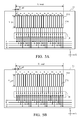
- FIGs. 5A and 5B are plane views of a light receiving surface of a light receiving element array illustrated in FIG. 1 according to the first embodiment.
- FIGs. 6A and 6B illustrate a relationship between a detected signal and a scale position according to the first embodiment.
- FIG. 7 is a partially enlarged plane view of a track according to the second embodiment.
- FIG. 8 is a partially enlarged plane view of FIG. 7 according to the second embodiment.
- FIG. 9 is a plane view of a light receiving surface of a light receiving element array according to the second embodiment.
- FIGs. 10A and 10B illustrate a relationship between a detected signal and a scale position according to the second embodiment.
- FIG. 11 is a plane view of a light receiving surface of a light receiving element array according to the third embodiment.
- FIG. 12 illustrates a positional relationship between a patterned area and a reading area of a two-track detector according to the third embodiment.
- FIG. 1 is a block diagram of an optical encoder according to this embodiment.
- the encoder includes a sensor unit 10 attached to a fixed unit, a scale 20 attached to a movable unit (not illustrated), a signal processor 30, and a storage 40.
- the relationship between the fixed unit and the movable unit may be reversed, as long as the sensor unit 10 and the scale 20 are configured to move relatively to each other.
- the sensor unit 10 is an integrated sensor unit of a light receiving unit and a light emitting unit, and includes a light source 12 including a light emitting diode ("LED") and a light receiving IC 14 including a light receiving element array 16 in the same package.
- the light receiving element array 16 serves as a detector array that includes a plurality of detectors configured to detect the energy distribution from the pattern of the scale 20 and arranged in an X direction as a moving direction (or a length measuring direction) of the scale 20 (or the movable unit).
- the energy is light in this embodiment, but as described later, the energy type is not limited to the light and may be include magnetism and electricity.
- the scale 20 has a track 21, which is patterned as a pattern row.
- the pattern row has a plurality of patterns made of a chromium reflective film on a glass substrate.
- the pattern is used to spatially modulate the energy distribution.
- Each track 21 includes a plurality of areas, which are periodically arranged in a Y direction perpendicular to the X direction and have different pitches (modulation periods) in the X direction.
- a "pitch" (modulation period), as used herein, means a space period of the patterns formed in a track in the X direction.
- the pitch (modulation period) is a reciprocal of a spatial frequency (or a value proportioned to the reciprocal). For example, when there are two types of areas, a first area has a first pitch (first modulation period) in the X direction, and a second area has a second pitch (second modulation period) in the X direction.
- An area of the first modulation period is not necessarily separated from an area of the second modulation period, and both areas may overlap each other.
- the light receiving element array 16 in this embodiment receives light reflected on the pattern of the scale 20, but this embodiment is applicable to the light receiving element array 16 configured to receive transmitted light through the pattern of the scale 20. In other words, it is sufficient that the light receiving element array 16 receives the light from the pattern of the scale 20.
- the signal processor 30 processes an output signal of the light receiving element array 16 in the sensor unit 10, and converts it into positional information.
- the signal processor 30 also performs interpolation processing to an encoder signal obtained by the sensor unit 10, and writing and reading of the signal for the storage 40.
- the signal processor 30 includes a noise filter (not illustrated), an amplifier (not illustrated), an A/D converter (not illustrated), a signal separator 31, a first phase acquirer 32, a second phase acquirer 33, and a positional information acquirer 34.
- the second phase acquirer 33 may be omitted.
- the signal separator 31 serves to separate an output from the light receiving element array 16 into a signal corresponding to each area of the track 21.
- the signal separator 31 sends a signal used to switch a connection of a switching circuit, if any, in the light receiving IC 14, or separates the signal using a fast Fourier transform ("FFT") when the light receiving IC 14 has no switching circuit.
- FFT fast Fourier transform
- the signal separator 31 may separate the signal by providing light receiving elements having different light receiving surfaces for each pattern pitch of the light receiving element array 16.
- the first phase acquirer 32 acquires a (first) phase of the energy distribution of the first area by performing an arc tangent operation for an output (digital) signal from the light receiving element array 16A (corresponding to the first area).
- the first phase acquirer 32 may serve as a relative position signal acquirer, which will be described later.
- the "relative position,” as used herein, means a variation amount of the position or a variation direction or amount of the position per unit time or per sampling period (used to obtain the position signal).
- the relative position may be a variation direction or amount of the position at reference time (when the power is turned on or at predetermined reference timing).
- the second phase acquirer 33 acquires a (second) phase of the energy distribution of the second area by performing an arc tangent operation for an output (digital) signal from the light receiving element array 16A (corresponding to the second area).
- a third phase acquirer etc. may be provided accordingly.
- the positional information acquirer 34 acquires positional information of the scale 20.
- the positional information acquirer 34 may include a relative position information acquirer configured to acquire a relative position signal representative of a relative position of the scale 20 and an absolute position information acquirer configured to acquire an absolute position signal representative of an absolute position of the scale 20.
- the "absolute position,” as used herein, means a position of a driver to an apparatus that includes the driver, and is different from a variation amount of the position to the position at the predetermined reference timing. Once the absolute position) is determined, the position of the driver to the apparatus is uniquely determined.
- a scale is arranged onto one of the driver and the fixed or movable unit that does not move with the driver, and a detector array is arranged onto the other. Thereby, the position of the driver having the scale relative to the fixed unit (apparatus body side) having the detector array becomes detectable.
- a divergent light flux emitted from the light source 12 in the sensor unit 10 is irradiated onto the track 21 of the scale 20, and the light flux reflected on the track 21 is received by the light receiving element array 16 in the sensor unit 10.
- the light receiving element array 16 receives an image in which a reflective index distribution of the track 21 is magnified twice.
- the light flux received by the light receiving element array 16 is converted into an electric signal, and sent as an encoder signal to the signal processor 30.
- the signal processor 30 converts the output from the light receiving element array 16 into positional information, and precisely obtains and outputs the information of the position of the scale 20.
- FIG. 2 is a partially enlarged plane view of the track 21A according to the first embodiment applicable to the track 21 illustrated in FIG. 1 .
- the track 21A two types of areas (23 and 25) alternate in the Y direction perpendicular to the moving direction (X direction) of the scale 20, and one track is set to a range that contains the overall width illustrated in FIG. 2 (that can be scanned on the light receiving surface of the light receiving array 16A).
- the area 23 corresponds to the above first area
- the area 25 corresponds to the above second area.
- a white portion is a non-reflector 22 configured to transmit or absorb the light.
- FIG. 3 is an enlarged plane view of the area 23 for one period in the X direction.
- Each pattern includes the non-reflector 22, and a reflector 24 made of a reflective film and configured to reflect light.
- the pitch P1 serves as the above first modulation period.
- a width of the reflector 24 in the X direction is different with a position of the area 23 in the Y direction.
- the width of the reflector 24 In an area distant by a distance of w1 ⁇ 1/8 or less from the center in the Y direction, the width of the reflector 24 is P1 ⁇ 23/30 in the X direction.
- the width of the reflector 24 In an area distant by a distance of w1 ⁇ 1/8 to w1 ⁇ 1/4 from the center in the Y direction, the width of the reflector 24 is P1 ⁇ 17/30 in the X direction.
- the width of the reflector 24 In an area distant by a distance of w1 ⁇ 1/4 to w1 ⁇ 3/8 from the center in the Y direction, the width of the reflector 24 is P1 ⁇ 13/30 in the X direction. In an area distant by a distance of w1 ⁇ 3/8 to w1 ⁇ 1/2 from the center in the Y direction, the width of the reflector 24 is P1 ⁇ 7/30 in the X direction.
- FIG. 4 is an enlarged plane view of the area 25 for one period in the X direction.
- Each pattern includes a non-reflector 22 and reflectors 26, 27 each made of a reflective film and configured to reflect light.
- the pitch P2 serves as the above second modulation period.
- a width of each of the reflector 26 in the X direction is different with a position of the area 25 in the Y direction.
- the width of the reflector 26 In an area distant by a distance of w2 ⁇ 1/6 or less from the center in the Y direction, the width of the reflector 26 is P2 ⁇ 70/96 in the X direction.
- the reflector 27 is formed with a width of P2 ⁇ 3/96 from each of both ends of the period.
- the width of the reflector 26 is P2 ⁇ 54/96 in the X direction.
- the width of the reflector 26 is P2 ⁇ 22/96 in the X direction.
- FIGs. 5A and 5B are plane views of the light receiving surface of the light receiving element array 16A according to the first embodiment applicable to the light receiving element array 16 illustrated in FIG. 1 .
- forty-eight light receiving elements 17A are arranged with a pitch of 50 ⁇ m in the X direction:
- One light receiving element 17A has a width X_pd of 50 ⁇ m in the X direction, and a width Y_pd of 800 ⁇ m in the Y direction.
- An overall width X_total of the light receiving element array 16A is 1,200 ⁇ m.
- the detectable range on the scale is 400 ⁇ m in the Y direction and 600 ⁇ m in the X direction.
- the detectable range on the scale contains four lines in the Y direction, and each line includes, in the position detecting direction, the area 23 with a pitch of 100 ⁇ m and the area 25 with a pitch of 202 ⁇ m.
- each light receiving element 17A is switched by a switching circuit 18, and selectively connected to the four subsequent preamplifiers (not illustrated).
- Corresponding light receiving elements 17A are connected to output terminals A+, B+, A-, and B- (representative of A+ phase, B+ phase A- phase and B- phase) of four preamplifiers, and the switching circuit 18 is configured to output four-phase sign wave outputs S(A+), S(B+), S(A-), and S(B-).
- the switching circuit 18 can switch a connection between the light receiving element 17A and the output terminal on the basis of the input from the signal separator 31 in the signal processor 30. As a result, an electrically added interval is switched in the plurality of light receiving elements 17A.
- relative phases of the four-phase sine wave signals have the following relationship with S(A+) as a reference: S(B+) shifts by about +90°, S (A-) shifts by about +180° and S(B-) shifts by about +270°.
- the signal processor 30 generates two-phase sine wave signals S(A) and S(B) in which a DC component is eliminated, by performing the following operations for the four-phase sine wave outputs S(A+), S(B+), S(A-), and S(B-):
- an error component "e” can be separated by an addition and a subtraction between the two-phase sine wave signals S(A) and S(B) as follows:
- S A + S B 2 ⁇ cos ⁇ - ⁇ / 4 sin e / 2 - ⁇ / 4 -
- S A + S B 2 ⁇ sin ⁇ - ⁇ / 4 cos e / 2 - ⁇ / 4
- e the relative phase difference error
- the relative phase difference error "e” may be stored through the initialization.
- the amplitude component 2 ⁇ sin(e(x)/2- ⁇ /4) is obtained from (maximum value - minimum value)/2 of S(A)+S(B) in the predetermined range in the X direction
- the amplitude component 2 ⁇ cos(e(x)/2- ⁇ /4) is obtained from (maximum value - minimum value) /2 of -S(A)+S(B) in the predetermined range in the X direction.
- These values may be stored in the storage 40. In this case, it is possible to correct mounting height shifts between the light source 12 and the light receiving element array 16A and the relative inclination between the scale 20 and the sensor.
- S(A)' is set to S (A) and S(B)' is set to S(B).
- the first phase acquirer 32 in the signal processor 30 acquires a phase (signal) ⁇ 1 of the energy distribution for the area 23 using the following operation and S(A) and S(B) when the input to the switching circuit 18 has a high level.
- ATAN2[Y, X] is an arc tangent function that determines a quadrant and converts it into a phase between 0 and 2n.
- ⁇ ⁇ 1 ATAN ⁇ 2 S A , S B
- the second phase acquirer 33 in the signal processor 30 acquires a phase (signal) ⁇ 2 of the energy distribution for the area 25 using the following operation and S(A) and S(B) when the input to the switching circuit 18 has a low level.
- ⁇ ⁇ 2 ATAN ⁇ 2 S A , S B
- the position signal acquirer of this embodiment acquires the output of the first phase acquirer 32 as the relative position signal. Information of which period the scale 20 is located at from the measurement starting position when the period is predetermined can be obtained, by counting a change of the relative position signal.
- the position signal acquirer of this embodiment generates a Vernier signal, which will be described later, based on the outputs of the first phase acquirer 32 and the second phase acquirer 33, and outputs information of the absolute position of the scale 20.
- Signals ⁇ 1 and ⁇ 2 can be obtained at almost the same position without a time difference before and after switching of the input into the switching circuit 18.
- the light receiving element array 16A can be made smaller than the conventional structure that separately includes the light receiving element 17A used to obtain the phase signal ⁇ 1 and the light receiving element 17A used to obtain the phase signal ⁇ 2.
- the synchronism may deteriorate when the scale 20 quickly moves, but can be maintained by obtaining a plurality of phases and by averaging the phases.
- S(A+), S(A-), S(B+) and S(B-) are obtained with a detecting pitch of 100 ⁇ m, and the level of the input into the switching circuit 18 is switched from the high level to the low level.
- S(A+), S(A-), S(B+) and S(B-) are obtained with a detecting pitch of 200 ⁇ m
- the level of the input into the switching circuit 18 is switched from the low level to the high level
- S(A+), S(A-), S (B+) and S (B-) are again obtained with a detecting pitch of 100 ⁇ m.
- An interval of the acquisition timing is maintained approximately constant.
- the synchronism between ⁇ 1 and ⁇ 2 can be improved by averaging the first ⁇ 1 and the second ⁇ 1 obtained through the above operations.
- FIG. 6A illustrates a relationship between the thus obtained Vernier signal Sv and the scale position.
- the period Tv of the Vernier signal Sv becomes 10.1 mm from Expression 15, and this is a detectable range. Since the detectable range on the scale in the light receiving element array length is a range of 600 ⁇ m in the X direction, the detectable range is much longer than a detectable range of the light receiving element array length.
- the Vernier signal as an absolute position signal, the absolute position of the scale in the moving direction can be detected in a wide range.
- FIG. 6B illustrates a relationship between the phase output ⁇ 1 and the scale position before the arc tangent calculation is performed.
- the phase output ⁇ 1 is used for the relative position signal (incremental signal) representative of the relative position of the scale 20.
- the relative position signal incrementmental signal
- the moving range detectable by the Vernier signal cannot exceed the detecting width Wpd on the scale when the subtraction is performed without multiplying ⁇ 1 and ⁇ 2 by the coefficients.
- n ⁇ 1 and m ⁇ 1 are 2 ⁇ n and 2 ⁇ m. If n and m are integers, the continuity is maintained because the subtracted result or a difference before and after the return points becomes integer times as large as 2n.
- Tv P ⁇ 1 ⁇ P ⁇ 2 / m ⁇ P ⁇ 1 - n ⁇ P ⁇ 2
- the period Tv of the detectable range becomes wider than the detecting width Wpd: m ⁇ P ⁇ 1 - n ⁇ P ⁇ 2 ⁇ P ⁇ 1 - P ⁇ 2
- the detectable range becomes much wider than the detecting width Wpd.
- n and n may be selected from small integers, because the phase difference errors contained in ⁇ 1 and ⁇ 2 are n times and m times in the Vernier signal Sv.
- n and m is 1 and 2.
- a magnetic encoder and an electrostatic encoder can also exhibit similar effects.
- a magnetic material is utilized for the scale 20, and a magnetic polarity distribution is formed with a shape similar to the reflective film of the scale 20 of this embodiment.
- a magnetic field detector array is arranged closely to this scale for detections.
- a conductive electrode pattern is formed in a shape similar to the scale reflective film of this embodiment, and another electrode pattern array is closely opposed for detections.
- an absolute position signal can be precisely obtained or detected in a wide range without increasing the size of the sensor.
- FIG. 7 is a partially enlarged plane view of a track 21B according to a second embodiment applicable to the track 21 illustrated in FIG. 1 .
- the track 21B three types of areas (23, 25, and 28) alternate in the Y direction perpendicular to the moving direction (X direction) of the scale 20, and one track is set to a range that contains the overall width illustrated in FIG. 7 (that can be scanned on the light receiving surface of the light receiving array 16B).
- the area 23 includes a pattern row in which a pattern illustrated in FIG. 3 is arranged every pitch P1 in the X direction (which is 99.50249 ⁇ m).
- the width W1 of the area 23 is 50 ⁇ m in the Y direction. Similar to the first embodiment, a width of the reflector 24 in the X direction differs according to a position of the area 23 in the Y direction.
- a width W2 of the area 25 is 50 ⁇ m in the Y direction. Similar to the first embodiment, a width of the reflector 26 in the X direction differs according to a position of the area 25 in the Y direction.
- FIG. 8 is an enlarged plane view of the area 28 in the X direction for one period.
- Each pattern includes a non-reflector 22 and a reflector 29 that is made of a reflective film and configured to reflect light.
- a width W3 of the area 28 in the Y direction is 50 ⁇ m.
- the width of the reflector 29 is P3 ⁇ 185/240 in the X direction.
- the width of the reflector 29 is P3 ⁇ 141/240 in the X direction.
- the width of the reflector 29 is P3 ⁇ 105/240 in the X direction.
- the width of the reflector 29 is P3 ⁇ 61/240 in the X direction.
- FIG. 9 is a plane view of the light receiving surface of the light receiving element array 16B according to the second embodiment applicable to the light receiving element array 16 illustrated in FIG. 1 .
- the light receiving element array 16B is a so-called linear sensor array configured to sequentially take an output corresponding to a light receiving amount of each light receiving element 17B in synchronization with the clock timing.
- 128 light receiving elements 17B are arranged with a pitch of 12.5 ⁇ m in the X direction: Its width Y_pd in the Y direction is 600 ⁇ m, and its overall width X_total is 1,600 ⁇ m in the X direction.
- the detectable range on the scale is 300 ⁇ m in the Y direction and 800 ⁇ m in the X direction.
- the detectable range on the scale contains two lines in the Y direction, and each line includes the areas 23, 25 and 28.
- a method for separating each periodical signal component of each of the areas 23, 25, and 28 from a linear image signal V output from an output unit 19 of the light receiving element array 16B may employ a Fourier transform or a conversion into four-phase sine waves corresponding to each period, as in the first embodiment.
- ⁇ 1 is a phase of a signal corresponding to the area 23 (with a period of 99.50249 ⁇ m).
- ⁇ 2 is a phase of a signal corresponding to the area 25 (with a period of 200 ⁇ m).
- ⁇ 3 is a phase of a signal corresponding to the area 28 (with a period of 769.23077 ⁇ m) .
- FIG. 10A illustrates a relationship between ⁇ a and the scale position.
- FIG. 10B illustrates a relationship between ⁇ b and the scale position.
- the signal processor 30 synchronizes the superordinate signal C with ⁇ b, calculates, based on the superordinate signal C, which period of ⁇ b the current position corresponds to, and obtains a position signal (medium signal M expressed by the following expression) having positional accuracy of ⁇ b by connecting ⁇ b.
- M 2 ⁇ ⁇ ⁇ ROUND ( Ta / Tb ⁇ C - ⁇ b / 2 ⁇ ⁇ + ⁇ b ⁇ Tb / Ta
- ROUND[x] is a function that converts a value into an integer closest to x.
- the signal processor 30 synchronizes the medium signal M with ⁇ 3, calculates which period of ⁇ 3 the current position is located at, using the medium signal M, and obtains a position signal (subordinate signal F expressed in the following expression) having the positional accuracy of ⁇ 3 by connecting ⁇ 3.
- F 2 ⁇ ⁇ ⁇ ROUND ( Ta / P ⁇ 3 ⁇ M - ⁇ ⁇ 3 / 2 ⁇ ⁇ + ⁇ ⁇ 3 ⁇ P ⁇ 3 / Ta
- the signal processor 30 synchronizes the subordinate signal F with ⁇ 1, calculates which period of ⁇ 1 the current position is located at, using the subordinate signal F, and obtains an absolute position signal ABS having the positional accuracy of ⁇ 1 by connecting ⁇ 1.
- ABS ROUND ( Ta / P ⁇ 1 ⁇ F - ⁇ ⁇ 1 / 2 ⁇ ⁇ + ⁇ ⁇ 1 / 2 ⁇ ⁇ ⁇ P ⁇ 1 ⁇ m
- This embodiment generates the absolute position signal ABS having positional precision of ⁇ 1 as the relative position signal, and requires no relative position signal.
- the absolute position signal ABS may be generated even in the first embodiment. This embodiment can more precisely obtain an absolute position signal than the first embodiment.
- FIG. 11 is a plane view that illustrates a light receiving surface of a light receiving element array 16C according to the third embodiment applicable to the light receiving element array 16 illustrated in FIG. 1 .
- the light receiving element array 16C is divided into two groups in the Y direction, and each row has a different pitch and the different number of elements.
- each light receiving element 17C1 serving as a first detector is arranged with a pitch of 50 ⁇ m in the X direction.
- Each light receiving element 17C1 has a width X_pd1 of 50 ⁇ m in the X direction, and a width Y_pd1 of 800 ⁇ m in the Y direction.
- An overall width X_total is 1,200 ⁇ m. Since the projected pattern on the scale is magnified twice, the detectable range on the scale is 400 ⁇ m in the Y direction and 600 ⁇ m in the X direction.
- the detectable range on the scale contains four lines in the Y direction, and each line includes the area 23 with a pitch of 100 ⁇ m in the position detecting direction, and the area 25 with a pitch of 202 ⁇ m.
- each light receiving element 17C2 serving as a second detector is arranged with a pitch of 100 ⁇ m in the X direction.
- Each light receiving element 17C2 has a width X_pd2 of 100 ⁇ m in the X direction, and a width Y_pd2 of 800 ⁇ m in the Y direction.
- An overall width X_total is 1,200 ⁇ m. Since the projected pattern on the scale is magnified twice, the detectable range on the scale is 400 ⁇ m in the Y direction and 600 ⁇ m in the X direction.
- the detectable range on the scale contains four lines in the Y direction, and each line includes the area 23 with a pitch of 100 ⁇ m in the position detecting direction, and the area 25 with a pitch of 202 ⁇ m.
- the signal processor 30 generates two-phase sine signals S(A1) and S(B1) in which a DC component is removed, by the following expressions with the four-phase sine signal S(A1+), S(B1+), S(A1-), and S(B1-) obtained from the light receiving elements 17C1 in the first row:
- S A ⁇ 1 S ⁇ A ⁇ 1 + - S ⁇ A ⁇ 1 -
- S B ⁇ 1 S ⁇ B ⁇ 1 + - S ⁇ B ⁇ 1 -
- the signal processor 30 generates two-phase sine wave signals S(A2) and S(B2) in which a DC component is eliminated, by performing the following expressions for the four-phase sine wave outputs S(A2+), S(B2+), S(A2-), and S(B2-) obtained from the light receiving elements 17C2 in the second row.
- S A ⁇ 2 S ⁇ A ⁇ 2 + - S ⁇ A ⁇ 2 -
- S B ⁇ 2 S ⁇ B ⁇ 2 + - S ⁇ B ⁇ 2 -
- the subsequent processing is similar to that of the first embodiment.
- FIG. 12 illustrates a reading area of each sensor and a position shiftable range in the Y direction when each light receiving element scans a separate periodic pattern.
- this embodiment simultaneously receives images from different periodic patterns and detectably separates only a necessary signal.
- the above limitation is not applied and a signal can be stably and precisely obtained.
- this embodiment detects a different period with a separate light receiving element and thus requires no switching processing. Therefore, this embodiment is more effective than the first embodiment in a system that emphasizes the time synchronism between periodic signals.
- the present invention is not limited to the encoder of this embodiment, and is applicable to another apparatus incorporated with the encoder of the present invention, such as a lens apparatus, an image-pickup apparatus, a manufacturing apparatus, and an apparatus that contains a movable object or unit.
- the apparatus incorporated with the encoder may be referred to as a (position detecting) apparatus configured to detect a position.
- the apparatus incorporated with the encoder characteristically includes a movable unit that is movable relative to an apparatus body, and the encoder according to the present invention configured to detect a position of the movable unit (relative to the apparatus body).
- One illustrative example of the apparatus incorporated with the encoder is a lens apparatus that includes a zoom lens unit that is movable during zooming or a lens apparatus that includes a focusing lens unit that is movable during focusing.
- the encoder of this embodiment can detect a position of the lens unit.
- the encoder of the present invention is applied to an apparatus, such as a facsimile machine, a printer, and a copier, configured to output or input a sheet of paper
- the encoder of this embodiment can detect a position of the movable unit in the paper carrying system in the apparatus.
- the encoder of this embodiment can detect a position of a movable unit, such as a stage, a tool, or a belt in the manufacturing apparatus body.
- a movable unit such as a stage, a tool, or a belt in the manufacturing apparatus body.
- the encoder of this embodiment can detect a position of the movable object.
- An encoder includes a scale, a detector array that includes a plurality of detectors, and a signal processor configured to process and convert into positional information, an output signal from the detector array.
- the signal processor includes a first phase acquirer, a second phase acquirer, and a positional information acquirer configured to acquire Sv as a position signal that represents a position of the scale.
- ⁇ 1 is a first phase acquired by the first phase acquirer
- ⁇ 2 is a second phase acquired by the second phase acquirer
- P1 is the first modulation period
- P2 is the second modulation period.
Landscapes
- Physics & Mathematics (AREA)
- General Physics & Mathematics (AREA)
- Optical Transform (AREA)
- Transmission And Conversion Of Sensor Element Output (AREA)
Applications Claiming Priority (1)
| Application Number | Priority Date | Filing Date | Title |
|---|---|---|---|
| JP2011089745A JP5791340B2 (ja) | 2011-04-14 | 2011-04-14 | エンコーダ |
Publications (3)
| Publication Number | Publication Date |
|---|---|
| EP2511668A2 true EP2511668A2 (de) | 2012-10-17 |
| EP2511668A3 EP2511668A3 (de) | 2014-08-20 |
| EP2511668B1 EP2511668B1 (de) | 2018-08-22 |
Family
ID=46045764
Family Applications (1)
| Application Number | Title | Priority Date | Filing Date |
|---|---|---|---|
| EP12163893.6A Active EP2511668B1 (de) | 2011-04-14 | 2012-04-12 | Kodierer |
Country Status (3)
| Country | Link |
|---|---|
| US (1) | US9127967B2 (de) |
| EP (1) | EP2511668B1 (de) |
| JP (1) | JP5791340B2 (de) |
Cited By (2)
| Publication number | Priority date | Publication date | Assignee | Title |
|---|---|---|---|---|
| CN103674081A (zh) * | 2012-08-31 | 2014-03-26 | 佳能株式会社 | 标尺、编码器、透镜装置以及图像拾取系统 |
| EP2754999A1 (de) * | 2012-12-28 | 2014-07-16 | Canon Kabushiki Kaisha | Skala, Verschiebungserkennungsvorrichtung, Linsenvorrichtung, Bildaufnahmesystem, und Montagevorrichtung |
Families Citing this family (17)
| Publication number | Priority date | Publication date | Assignee | Title |
|---|---|---|---|---|
| JP6032924B2 (ja) | 2011-04-13 | 2016-11-30 | キヤノン株式会社 | エンコーダ |
| JP5755009B2 (ja) | 2011-04-14 | 2015-07-29 | キヤノン株式会社 | エンコーダ |
| JP5755010B2 (ja) | 2011-04-14 | 2015-07-29 | キヤノン株式会社 | エンコーダ |
| JP5932285B2 (ja) * | 2011-10-14 | 2016-06-08 | キヤノン株式会社 | エンコーダおよびこれを備えた装置 |
| JP6308739B2 (ja) * | 2013-08-29 | 2018-04-11 | キヤノン株式会社 | 位置検出装置及びそれを有するレンズ装置、画像読取装置及び画像形成装置 |
| JP6253320B2 (ja) * | 2013-09-13 | 2017-12-27 | キヤノン株式会社 | エンコーダおよびこれを用いた装置 |
| JP6408804B2 (ja) * | 2014-07-03 | 2018-10-17 | キヤノン株式会社 | 位置検出装置及びそれを有するレンズ装置及び撮影装置 |
| JP2016033452A (ja) * | 2014-07-30 | 2016-03-10 | オリンパス株式会社 | エンコーダの内挿装置、エンコーダの内挿装置の制御方法、エンコーダの内挿装置の制御プログラム |
| JP6486097B2 (ja) * | 2014-12-19 | 2019-03-20 | キヤノン株式会社 | 位置検出装置、レンズ装置、撮像システム、工作装置、位置検出方法、プログラム、および、記憶媒体 |
| US9772202B1 (en) * | 2016-07-01 | 2017-09-26 | Mitutoyo Corporation | Absolute position encoder combining signals of two widely separated wavelengths |
| DE102018200449A1 (de) | 2018-01-12 | 2019-07-18 | Dr. Johannes Heidenhain Gmbh | Positionsmesseinrichtung |
| JP7148337B2 (ja) * | 2018-09-14 | 2022-10-05 | キヤノン株式会社 | 位置検出装置、リソグラフィ装置、力覚センサ及び力覚センサを有する装置 |
| US11874144B2 (en) * | 2020-07-28 | 2024-01-16 | Li Lin | Displacement measurement system |
| US12385764B2 (en) | 2022-12-30 | 2025-08-12 | Mitutoyo Corporation | Absolute position encoder utilizing single track configuration |
| US12546628B2 (en) | 2023-10-30 | 2026-02-10 | Mitutoyo Corporation | Inductive encoder with shield structures |
| US12553746B2 (en) | 2023-12-20 | 2026-02-17 | Mitutoyo Corporation | Measuring instrument with linear encoder tracks and arc motion |
| US12553747B2 (en) | 2023-12-20 | 2026-02-17 | Mitutoyo Corporation | Measuring instrument with arc encoder tracks |
Citations (1)
| Publication number | Priority date | Publication date | Assignee | Title |
|---|---|---|---|---|
| JP2009198318A (ja) | 2008-02-21 | 2009-09-03 | Mitsutoyo Corp | 光電式エンコーダ |
Family Cites Families (23)
| Publication number | Priority date | Publication date | Assignee | Title |
|---|---|---|---|---|
| JPS5530603A (en) * | 1978-08-25 | 1980-03-04 | Nippon Telegr & Teleph Corp <Ntt> | Position detector |
| US4291976A (en) | 1980-03-10 | 1981-09-29 | Sperry Corporation | Digital fiber optic position sensor |
| JPS6363916A (ja) * | 1986-09-04 | 1988-03-22 | Mitsutoyo Corp | 光学式変位検出器 |
| JPS6363917A (ja) * | 1986-09-04 | 1988-03-22 | Mitsutoyo Corp | 光学式変位検出器 |
| JPS6365316A (ja) * | 1986-09-05 | 1988-03-23 | Mitsutoyo Corp | 光学式変位検出装置 |
| JPS6365315A (ja) * | 1986-09-05 | 1988-03-23 | Mitsutoyo Corp | 光学式変位検出装置 |
| JPH01229905A (ja) * | 1988-03-10 | 1989-09-13 | Mitsutoyo Corp | 変位検出器 |
| JPH0295203A (ja) * | 1988-09-30 | 1990-04-06 | Matsushita Electric Ind Co Ltd | 位置合わせ装置 |
| US5069547A (en) * | 1988-11-23 | 1991-12-03 | The Boeing Company | Multitrack multilevel sensing system with error detecting |
| US5699058A (en) | 1994-03-17 | 1997-12-16 | Copal Company Limited | Absolute encoder generating phase-shifted triangular waveforms to produce multi-bit signals |
| JPH09196705A (ja) | 1996-01-23 | 1997-07-31 | Mitsutoyo Corp | 変位測定装置 |
| US6707029B1 (en) | 1999-01-22 | 2004-03-16 | Citizen Watch Co., Ltd. | Optical displacement measuring apparatus having light receiving arrays |
| US6512222B2 (en) | 2000-02-03 | 2003-01-28 | Mitutoyo Corporation | Displacement measuring apparatus |
| US6713756B2 (en) | 2000-05-09 | 2004-03-30 | Olympus Corporation | Optical encoder and optical rotary encoder |
| US6765195B1 (en) | 2001-05-22 | 2004-07-20 | The United States Of America As Represented By The Administrator Of The National Aeronautics And Space Administration | Method and apparatus for two-dimensional absolute optical encoding |
| JP2007248359A (ja) | 2006-03-17 | 2007-09-27 | Citizen Holdings Co Ltd | 位置検出装置 |
| US7521669B2 (en) | 2006-06-02 | 2009-04-21 | Avago Technologies Ecbu Ip (Singapore) Pte. Ltd. | Multi-bit absolute position optical encoder with reduced number of tracks |
| US8188420B2 (en) * | 2009-11-14 | 2012-05-29 | Avago Technologies Ecbu Ip (Singapore) Pte. Ltd. | High resolution optical encoder systems having a set of light detecting elements each comprising a pair of complementary detectors (as amended) |
| JP5887064B2 (ja) | 2010-04-28 | 2016-03-16 | 株式会社ミツトヨ | 光学式エンコーダ |
| US8309906B2 (en) | 2010-06-10 | 2012-11-13 | Mitutoyo Corporation | Absolute optical encoder with long range intensity modulation on scale |
| JP6032924B2 (ja) | 2011-04-13 | 2016-11-30 | キヤノン株式会社 | エンコーダ |
| JP5755009B2 (ja) | 2011-04-14 | 2015-07-29 | キヤノン株式会社 | エンコーダ |
| JP5755010B2 (ja) | 2011-04-14 | 2015-07-29 | キヤノン株式会社 | エンコーダ |
-
2011
- 2011-04-14 JP JP2011089745A patent/JP5791340B2/ja active Active
-
2012
- 2012-04-12 EP EP12163893.6A patent/EP2511668B1/de active Active
- 2012-04-13 US US13/446,057 patent/US9127967B2/en active Active
Patent Citations (1)
| Publication number | Priority date | Publication date | Assignee | Title |
|---|---|---|---|---|
| JP2009198318A (ja) | 2008-02-21 | 2009-09-03 | Mitsutoyo Corp | 光電式エンコーダ |
Cited By (5)
| Publication number | Priority date | Publication date | Assignee | Title |
|---|---|---|---|---|
| CN103674081A (zh) * | 2012-08-31 | 2014-03-26 | 佳能株式会社 | 标尺、编码器、透镜装置以及图像拾取系统 |
| CN103674081B (zh) * | 2012-08-31 | 2016-08-10 | 佳能株式会社 | 标尺、编码器、透镜装置以及图像拾取系统 |
| US9778035B2 (en) | 2012-08-31 | 2017-10-03 | Canon Kabushiki Kaisha | Scale, encoder, lens apparatus, and image pickup system having a plurality of patterns with different modulating periods |
| EP2754999A1 (de) * | 2012-12-28 | 2014-07-16 | Canon Kabushiki Kaisha | Skala, Verschiebungserkennungsvorrichtung, Linsenvorrichtung, Bildaufnahmesystem, und Montagevorrichtung |
| US9464924B2 (en) | 2012-12-28 | 2016-10-11 | Canon Kabushiki Kaisha | Scale, displacement detection apparatus, lens apparatus, image pickup system, and assembling apparatus |
Also Published As
| Publication number | Publication date |
|---|---|
| US20120262731A1 (en) | 2012-10-18 |
| EP2511668B1 (de) | 2018-08-22 |
| JP5791340B2 (ja) | 2015-10-07 |
| EP2511668A3 (de) | 2014-08-20 |
| JP2012220458A (ja) | 2012-11-12 |
| US9127967B2 (en) | 2015-09-08 |
Similar Documents
| Publication | Publication Date | Title |
|---|---|---|
| EP2511668B1 (de) | Kodierer | |
| EP2511670B1 (de) | Kodierer | |
| EP2848898B1 (de) | Codierer- und Vorrichtung mit dem Codierer | |
| EP2511666B1 (de) | Codierer | |
| US9778035B2 (en) | Scale, encoder, lens apparatus, and image pickup system having a plurality of patterns with different modulating periods | |
| EP2434261B1 (de) | Optischer Drehgeber | |
| EP3035003B1 (de) | Positionsdetektionsvorrichtung, linsenvorrichtung, bildaufnahmesystem, werkzeugmaschinenvorrichtung, positionsdetektionsverfahren, programm und speichermedium | |
| EP2662668B1 (de) | Skala, Vernierkodierer und Vorrichtung damit | |
| US10215596B2 (en) | Position detection apparatus, lens apparatus, image pickup system, machine tool apparatus, exposure apparatus, position detection method, and non-transitory computer-readable storage medium which are capable of detecting reference position with high accuracy | |
| EP3290872B1 (de) | Codierer und vorrichtung damit | |
| EP2778626B1 (de) | Positionsdetektionsvorrichtung, Linsenvorrichtung, Bildaufnahmesystem, Werkzeugmaschinenvorrichtung, Positionsdetektionsverfahren, Programm und Speichermedium | |
| JP6440609B2 (ja) | 位置検出装置、レンズ装置、撮像システム、工作装置、露光装置、位置検出方法、プログラム、記憶媒体 | |
| JP2016014612A (ja) | エンコーダ |
Legal Events
| Date | Code | Title | Description |
|---|---|---|---|
| PUAI | Public reference made under article 153(3) epc to a published international application that has entered the european phase |
Free format text: ORIGINAL CODE: 0009012 |
|
| AK | Designated contracting states |
Kind code of ref document: A2 Designated state(s): AL AT BE BG CH CY CZ DE DK EE ES FI FR GB GR HR HU IE IS IT LI LT LU LV MC MK MT NL NO PL PT RO RS SE SI SK SM TR |
|
| AX | Request for extension of the european patent |
Extension state: BA ME |
|
| PUAL | Search report despatched |
Free format text: ORIGINAL CODE: 0009013 |
|
| AK | Designated contracting states |
Kind code of ref document: A3 Designated state(s): AL AT BE BG CH CY CZ DE DK EE ES FI FR GB GR HR HU IE IS IT LI LT LU LV MC MK MT NL NO PL PT RO RS SE SI SK SM TR |
|
| AX | Request for extension of the european patent |
Extension state: BA ME |
|
| RIC1 | Information provided on ipc code assigned before grant |
Ipc: G01D 13/06 20060101AFI20140717BHEP |
|
| 17P | Request for examination filed |
Effective date: 20150220 |
|
| RBV | Designated contracting states (corrected) |
Designated state(s): AL AT BE BG CH CY CZ DE DK EE ES FI FR GB GR HR HU IE IS IT LI LT LU LV MC MK MT NL NO PL PT RO RS SE SI SK SM TR |
|
| STAA | Information on the status of an ep patent application or granted ep patent |
Free format text: STATUS: EXAMINATION IS IN PROGRESS |
|
| 17Q | First examination report despatched |
Effective date: 20170207 |
|
| REG | Reference to a national code |
Ref country code: DE Ref legal event code: R079 Ref document number: 602012049990 Country of ref document: DE Free format text: PREVIOUS MAIN CLASS: G01D0013060000 Ipc: G01D0005347000 |
|
| GRAP | Despatch of communication of intention to grant a patent |
Free format text: ORIGINAL CODE: EPIDOSNIGR1 |
|
| STAA | Information on the status of an ep patent application or granted ep patent |
Free format text: STATUS: GRANT OF PATENT IS INTENDED |
|
| RIC1 | Information provided on ipc code assigned before grant |
Ipc: G01D 5/347 20060101AFI20180206BHEP |
|
| INTG | Intention to grant announced |
Effective date: 20180306 |
|
| RIN1 | Information on inventor provided before grant (corrected) |
Inventor name: NAGURA, CHIHIRO |
|
| GRAS | Grant fee paid |
Free format text: ORIGINAL CODE: EPIDOSNIGR3 |
|
| GRAA | (expected) grant |
Free format text: ORIGINAL CODE: 0009210 |
|
| STAA | Information on the status of an ep patent application or granted ep patent |
Free format text: STATUS: THE PATENT HAS BEEN GRANTED |
|
| AK | Designated contracting states |
Kind code of ref document: B1 Designated state(s): AL AT BE BG CH CY CZ DE DK EE ES FI FR GB GR HR HU IE IS IT LI LT LU LV MC MK MT NL NO PL PT RO RS SE SI SK SM TR |
|
| REG | Reference to a national code |
Ref country code: GB Ref legal event code: FG4D |
|
| REG | Reference to a national code |
Ref country code: CH Ref legal event code: EP |
|
| REG | Reference to a national code |
Ref country code: AT Ref legal event code: REF Ref document number: 1033034 Country of ref document: AT Kind code of ref document: T Effective date: 20180915 |
|
| REG | Reference to a national code |
Ref country code: IE Ref legal event code: FG4D |
|
| REG | Reference to a national code |
Ref country code: DE Ref legal event code: R096 Ref document number: 602012049990 Country of ref document: DE |
|
| REG | Reference to a national code |
Ref country code: NL Ref legal event code: MP Effective date: 20180822 |
|
| REG | Reference to a national code |
Ref country code: LT Ref legal event code: MG4D |
|
| PG25 | Lapsed in a contracting state [announced via postgrant information from national office to epo] |
Ref country code: IS Free format text: LAPSE BECAUSE OF FAILURE TO SUBMIT A TRANSLATION OF THE DESCRIPTION OR TO PAY THE FEE WITHIN THE PRESCRIBED TIME-LIMIT Effective date: 20181222 Ref country code: RS Free format text: LAPSE BECAUSE OF FAILURE TO SUBMIT A TRANSLATION OF THE DESCRIPTION OR TO PAY THE FEE WITHIN THE PRESCRIBED TIME-LIMIT Effective date: 20180822 Ref country code: NL Free format text: LAPSE BECAUSE OF FAILURE TO SUBMIT A TRANSLATION OF THE DESCRIPTION OR TO PAY THE FEE WITHIN THE PRESCRIBED TIME-LIMIT Effective date: 20180822 Ref country code: BG Free format text: LAPSE BECAUSE OF FAILURE TO SUBMIT A TRANSLATION OF THE DESCRIPTION OR TO PAY THE FEE WITHIN THE PRESCRIBED TIME-LIMIT Effective date: 20181122 Ref country code: SE Free format text: LAPSE BECAUSE OF FAILURE TO SUBMIT A TRANSLATION OF THE DESCRIPTION OR TO PAY THE FEE WITHIN THE PRESCRIBED TIME-LIMIT Effective date: 20180822 Ref country code: LT Free format text: LAPSE BECAUSE OF FAILURE TO SUBMIT A TRANSLATION OF THE DESCRIPTION OR TO PAY THE FEE WITHIN THE PRESCRIBED TIME-LIMIT Effective date: 20180822 Ref country code: FI Free format text: LAPSE BECAUSE OF FAILURE TO SUBMIT A TRANSLATION OF THE DESCRIPTION OR TO PAY THE FEE WITHIN THE PRESCRIBED TIME-LIMIT Effective date: 20180822 Ref country code: NO Free format text: LAPSE BECAUSE OF FAILURE TO SUBMIT A TRANSLATION OF THE DESCRIPTION OR TO PAY THE FEE WITHIN THE PRESCRIBED TIME-LIMIT Effective date: 20181122 Ref country code: GR Free format text: LAPSE BECAUSE OF FAILURE TO SUBMIT A TRANSLATION OF THE DESCRIPTION OR TO PAY THE FEE WITHIN THE PRESCRIBED TIME-LIMIT Effective date: 20181123 |
|
| REG | Reference to a national code |
Ref country code: AT Ref legal event code: MK05 Ref document number: 1033034 Country of ref document: AT Kind code of ref document: T Effective date: 20180822 |
|
| PG25 | Lapsed in a contracting state [announced via postgrant information from national office to epo] |
Ref country code: HR Free format text: LAPSE BECAUSE OF FAILURE TO SUBMIT A TRANSLATION OF THE DESCRIPTION OR TO PAY THE FEE WITHIN THE PRESCRIBED TIME-LIMIT Effective date: 20180822 Ref country code: AL Free format text: LAPSE BECAUSE OF FAILURE TO SUBMIT A TRANSLATION OF THE DESCRIPTION OR TO PAY THE FEE WITHIN THE PRESCRIBED TIME-LIMIT Effective date: 20180822 Ref country code: LV Free format text: LAPSE BECAUSE OF FAILURE TO SUBMIT A TRANSLATION OF THE DESCRIPTION OR TO PAY THE FEE WITHIN THE PRESCRIBED TIME-LIMIT Effective date: 20180822 |
|
| PG25 | Lapsed in a contracting state [announced via postgrant information from national office to epo] |
Ref country code: IT Free format text: LAPSE BECAUSE OF FAILURE TO SUBMIT A TRANSLATION OF THE DESCRIPTION OR TO PAY THE FEE WITHIN THE PRESCRIBED TIME-LIMIT Effective date: 20180822 Ref country code: RO Free format text: LAPSE BECAUSE OF FAILURE TO SUBMIT A TRANSLATION OF THE DESCRIPTION OR TO PAY THE FEE WITHIN THE PRESCRIBED TIME-LIMIT Effective date: 20180822 Ref country code: CZ Free format text: LAPSE BECAUSE OF FAILURE TO SUBMIT A TRANSLATION OF THE DESCRIPTION OR TO PAY THE FEE WITHIN THE PRESCRIBED TIME-LIMIT Effective date: 20180822 Ref country code: EE Free format text: LAPSE BECAUSE OF FAILURE TO SUBMIT A TRANSLATION OF THE DESCRIPTION OR TO PAY THE FEE WITHIN THE PRESCRIBED TIME-LIMIT Effective date: 20180822 Ref country code: AT Free format text: LAPSE BECAUSE OF FAILURE TO SUBMIT A TRANSLATION OF THE DESCRIPTION OR TO PAY THE FEE WITHIN THE PRESCRIBED TIME-LIMIT Effective date: 20180822 Ref country code: PL Free format text: LAPSE BECAUSE OF FAILURE TO SUBMIT A TRANSLATION OF THE DESCRIPTION OR TO PAY THE FEE WITHIN THE PRESCRIBED TIME-LIMIT Effective date: 20180822 Ref country code: ES Free format text: LAPSE BECAUSE OF FAILURE TO SUBMIT A TRANSLATION OF THE DESCRIPTION OR TO PAY THE FEE WITHIN THE PRESCRIBED TIME-LIMIT Effective date: 20180822 |
|
| REG | Reference to a national code |
Ref country code: DE Ref legal event code: R097 Ref document number: 602012049990 Country of ref document: DE |
|
| PG25 | Lapsed in a contracting state [announced via postgrant information from national office to epo] |
Ref country code: SM Free format text: LAPSE BECAUSE OF FAILURE TO SUBMIT A TRANSLATION OF THE DESCRIPTION OR TO PAY THE FEE WITHIN THE PRESCRIBED TIME-LIMIT Effective date: 20180822 Ref country code: SK Free format text: LAPSE BECAUSE OF FAILURE TO SUBMIT A TRANSLATION OF THE DESCRIPTION OR TO PAY THE FEE WITHIN THE PRESCRIBED TIME-LIMIT Effective date: 20180822 Ref country code: DK Free format text: LAPSE BECAUSE OF FAILURE TO SUBMIT A TRANSLATION OF THE DESCRIPTION OR TO PAY THE FEE WITHIN THE PRESCRIBED TIME-LIMIT Effective date: 20180822 |
|
| PLBE | No opposition filed within time limit |
Free format text: ORIGINAL CODE: 0009261 |
|
| STAA | Information on the status of an ep patent application or granted ep patent |
Free format text: STATUS: NO OPPOSITION FILED WITHIN TIME LIMIT |
|
| 26N | No opposition filed |
Effective date: 20190523 |
|
| PG25 | Lapsed in a contracting state [announced via postgrant information from national office to epo] |
Ref country code: SI Free format text: LAPSE BECAUSE OF FAILURE TO SUBMIT A TRANSLATION OF THE DESCRIPTION OR TO PAY THE FEE WITHIN THE PRESCRIBED TIME-LIMIT Effective date: 20180822 |
|
| REG | Reference to a national code |
Ref country code: CH Ref legal event code: PL |
|
| REG | Reference to a national code |
Ref country code: BE Ref legal event code: MM Effective date: 20190430 |
|
| PG25 | Lapsed in a contracting state [announced via postgrant information from national office to epo] |
Ref country code: LU Free format text: LAPSE BECAUSE OF NON-PAYMENT OF DUE FEES Effective date: 20190412 Ref country code: MC Free format text: LAPSE BECAUSE OF FAILURE TO SUBMIT A TRANSLATION OF THE DESCRIPTION OR TO PAY THE FEE WITHIN THE PRESCRIBED TIME-LIMIT Effective date: 20180822 |
|
| PG25 | Lapsed in a contracting state [announced via postgrant information from national office to epo] |
Ref country code: LI Free format text: LAPSE BECAUSE OF NON-PAYMENT OF DUE FEES Effective date: 20190430 Ref country code: CH Free format text: LAPSE BECAUSE OF NON-PAYMENT OF DUE FEES Effective date: 20190430 |
|
| PG25 | Lapsed in a contracting state [announced via postgrant information from national office to epo] |
Ref country code: BE Free format text: LAPSE BECAUSE OF NON-PAYMENT OF DUE FEES Effective date: 20190430 Ref country code: FR Free format text: LAPSE BECAUSE OF NON-PAYMENT OF DUE FEES Effective date: 20190430 |
|
| PG25 | Lapsed in a contracting state [announced via postgrant information from national office to epo] |
Ref country code: TR Free format text: LAPSE BECAUSE OF FAILURE TO SUBMIT A TRANSLATION OF THE DESCRIPTION OR TO PAY THE FEE WITHIN THE PRESCRIBED TIME-LIMIT Effective date: 20180822 |
|
| PG25 | Lapsed in a contracting state [announced via postgrant information from national office to epo] |
Ref country code: IE Free format text: LAPSE BECAUSE OF NON-PAYMENT OF DUE FEES Effective date: 20190412 |
|
| PG25 | Lapsed in a contracting state [announced via postgrant information from national office to epo] |
Ref country code: PT Free format text: LAPSE BECAUSE OF FAILURE TO SUBMIT A TRANSLATION OF THE DESCRIPTION OR TO PAY THE FEE WITHIN THE PRESCRIBED TIME-LIMIT Effective date: 20181222 |
|
| PG25 | Lapsed in a contracting state [announced via postgrant information from national office to epo] |
Ref country code: CY Free format text: LAPSE BECAUSE OF FAILURE TO SUBMIT A TRANSLATION OF THE DESCRIPTION OR TO PAY THE FEE WITHIN THE PRESCRIBED TIME-LIMIT Effective date: 20180822 |
|
| PG25 | Lapsed in a contracting state [announced via postgrant information from national office to epo] |
Ref country code: HU Free format text: LAPSE BECAUSE OF FAILURE TO SUBMIT A TRANSLATION OF THE DESCRIPTION OR TO PAY THE FEE WITHIN THE PRESCRIBED TIME-LIMIT; INVALID AB INITIO Effective date: 20120412 Ref country code: MT Free format text: LAPSE BECAUSE OF FAILURE TO SUBMIT A TRANSLATION OF THE DESCRIPTION OR TO PAY THE FEE WITHIN THE PRESCRIBED TIME-LIMIT Effective date: 20180822 |
|
| PG25 | Lapsed in a contracting state [announced via postgrant information from national office to epo] |
Ref country code: MK Free format text: LAPSE BECAUSE OF FAILURE TO SUBMIT A TRANSLATION OF THE DESCRIPTION OR TO PAY THE FEE WITHIN THE PRESCRIBED TIME-LIMIT Effective date: 20180822 |
|
| PGFP | Annual fee paid to national office [announced via postgrant information from national office to epo] |
Ref country code: DE Payment date: 20250319 Year of fee payment: 14 |
|
| PGFP | Annual fee paid to national office [announced via postgrant information from national office to epo] |
Ref country code: GB Payment date: 20260319 Year of fee payment: 15 |