EP2513488B1 - Turbocompresseur - Google Patents
Turbocompresseur Download PDFInfo
- Publication number
- EP2513488B1 EP2513488B1 EP10795284.8A EP10795284A EP2513488B1 EP 2513488 B1 EP2513488 B1 EP 2513488B1 EP 10795284 A EP10795284 A EP 10795284A EP 2513488 B1 EP2513488 B1 EP 2513488B1
- Authority
- EP
- European Patent Office
- Prior art keywords
- impeller
- flow
- channel
- inlet
- opening
- Prior art date
- Legal status (The legal status is an assumption and is not a legal conclusion. Google has not performed a legal analysis and makes no representation as to the accuracy of the status listed.)
- Active
Links
- 238000011144 upstream manufacturing Methods 0.000 claims description 8
- 230000015572 biosynthetic process Effects 0.000 description 6
- 230000002349 favourable effect Effects 0.000 description 6
- 238000005086 pumping Methods 0.000 description 4
- 238000009530 blood pressure measurement Methods 0.000 description 2
- 230000000087 stabilizing effect Effects 0.000 description 2
- 230000007423 decrease Effects 0.000 description 1
- 230000000694 effects Effects 0.000 description 1
- 239000002184 metal Substances 0.000 description 1
- 238000000926 separation method Methods 0.000 description 1
- 239000007787 solid Substances 0.000 description 1
- 230000006641 stabilisation Effects 0.000 description 1
- 238000011105 stabilization Methods 0.000 description 1
Images




Classifications
-
- F—MECHANICAL ENGINEERING; LIGHTING; HEATING; WEAPONS; BLASTING
- F04—POSITIVE - DISPLACEMENT MACHINES FOR LIQUIDS; PUMPS FOR LIQUIDS OR ELASTIC FLUIDS
- F04D—NON-POSITIVE-DISPLACEMENT PUMPS
- F04D29/00—Details, component parts, or accessories
- F04D29/40—Casings; Connections of working fluid
- F04D29/42—Casings; Connections of working fluid for radial or helico-centrifugal pumps
- F04D29/4206—Casings; Connections of working fluid for radial or helico-centrifugal pumps especially adapted for elastic fluid pumps
- F04D29/4213—Casings; Connections of working fluid for radial or helico-centrifugal pumps especially adapted for elastic fluid pumps suction ports
-
- F—MECHANICAL ENGINEERING; LIGHTING; HEATING; WEAPONS; BLASTING
- F04—POSITIVE - DISPLACEMENT MACHINES FOR LIQUIDS; PUMPS FOR LIQUIDS OR ELASTIC FLUIDS
- F04D—NON-POSITIVE-DISPLACEMENT PUMPS
- F04D27/00—Control, e.g. regulation, of pumps, pumping installations or pumping systems specially adapted for elastic fluids
- F04D27/02—Surge control
- F04D27/0207—Surge control by bleeding, bypassing or recycling fluids
-
- F—MECHANICAL ENGINEERING; LIGHTING; HEATING; WEAPONS; BLASTING
- F04—POSITIVE - DISPLACEMENT MACHINES FOR LIQUIDS; PUMPS FOR LIQUIDS OR ELASTIC FLUIDS
- F04D—NON-POSITIVE-DISPLACEMENT PUMPS
- F04D27/00—Control, e.g. regulation, of pumps, pumping installations or pumping systems specially adapted for elastic fluids
- F04D27/02—Surge control
- F04D27/0207—Surge control by bleeding, bypassing or recycling fluids
- F04D27/0215—Arrangements therefor, e.g. bleed or by-pass valves
-
- F—MECHANICAL ENGINEERING; LIGHTING; HEATING; WEAPONS; BLASTING
- F04—POSITIVE - DISPLACEMENT MACHINES FOR LIQUIDS; PUMPS FOR LIQUIDS OR ELASTIC FLUIDS
- F04D—NON-POSITIVE-DISPLACEMENT PUMPS
- F04D29/00—Details, component parts, or accessories
- F04D29/40—Casings; Connections of working fluid
- F04D29/42—Casings; Connections of working fluid for radial or helico-centrifugal pumps
- F04D29/44—Fluid-guiding means, e.g. diffusers
- F04D29/441—Fluid-guiding means, e.g. diffusers especially adapted for elastic fluid pumps
- F04D29/444—Bladed diffusers
-
- F—MECHANICAL ENGINEERING; LIGHTING; HEATING; WEAPONS; BLASTING
- F04—POSITIVE - DISPLACEMENT MACHINES FOR LIQUIDS; PUMPS FOR LIQUIDS OR ELASTIC FLUIDS
- F04D—NON-POSITIVE-DISPLACEMENT PUMPS
- F04D29/00—Details, component parts, or accessories
- F04D29/66—Combating cavitation, whirls, noise, vibration or the like; Balancing
- F04D29/68—Combating cavitation, whirls, noise, vibration or the like; Balancing by influencing boundary layers
- F04D29/681—Combating cavitation, whirls, noise, vibration or the like; Balancing by influencing boundary layers especially adapted for elastic fluid pumps
- F04D29/685—Inducing localised fluid recirculation in the stator-rotor interface
-
- F—MECHANICAL ENGINEERING; LIGHTING; HEATING; WEAPONS; BLASTING
- F05—INDEXING SCHEMES RELATING TO ENGINES OR PUMPS IN VARIOUS SUBCLASSES OF CLASSES F01-F04
- F05D—INDEXING SCHEME FOR ASPECTS RELATING TO NON-POSITIVE-DISPLACEMENT MACHINES OR ENGINES, GAS-TURBINES OR JET-PROPULSION PLANTS
- F05D2250/00—Geometry
- F05D2250/50—Inlet or outlet
- F05D2250/51—Inlet
Definitions
- turbocompressor comprising a compressor housing, in which an incoming gas volume flow through an inlet channel is fed to an impeller passage, is compressed in the impeller passage by an impeller and is discharged from the impeller passage via an outlet passage, and provided with a compressor housing, outside the impeller passage and the Inlet passage extending Strömungsumtechnischskanal, which opens with an inlet side opening in the inlet channel and with an impeller side opening in the impeller passage and which in response to a pressure difference between the openings a bypass volumetric flow
- turbo compressor comprising a compressor housing in which an incoming gas volume flow through an inlet channel supplied to an impeller passage is compressed in the impeller passage by an impeller and is discharged from the impeller passage via an outlet channel, and provided with an in the compressor housing au Outside of the impeller passage and the inlet channel extending flow bypass passage which opens with an inlet side opening in the inlet channel and with an impeller side opening in the impeller passage and which in response to a pressure difference between the openings
- Such a turbocompressor is for example from the EP 1 557 568 known.
- Such a turbocompressor is not designed with a view to the best possible operation in volume flows, which are far below the intended for the design point volume flow.
- the invention is therefore an object of the invention to improve a turbocompressor of the generic type such that it can be optimally operated at flow rates that are far below the intended for the design point volume flow.
- the flow cross-sectional area of the flow diversion channel increases steadily as it extends from the impeller-side opening to the inlet-side opening in order to obtain a favorable design of a bypass volumetric flow from the impeller-side opening to the inlet-side opening for flow stabilization in part-load operation.
- a particularly advantageous solution of a turbocompressor according to the invention provides that a flow cross-sectional area of the inlet-side opening is in the range between 2.5 times and 3 times the flow cross-sectional area of the impeller-side opening.
- the flow diversion channel is formed by channel segments arranged adjacent to each other with respect to an impeller axis in a circumferential direction, that is to say that the flow diversion channel does not extend continuously in the direction of rotation around the impeller channel, but is subdivided into such individual channel segments.
- the channel segments are separated from one another in the direction of rotation, so that a swirl generated in the region of the impeller is not transmitted through the flow diversion channel, but is decelerated in the flow diversion channel, so that in particular from the inlet-side opening of the flow diversion channel a swirl-free bypass flow exits.
- a particularly advantageous solution provides that the impeller-side opening of the flow diversion channel lies in a region of the impeller passage in which the impeller blades move.
- impeller-side opening of the flow diversion channel lies in the region between inlet-side ends of long impeller blades and inlet-side ends of short impeller blades.
- the impeller-side opening of the flow-diversion channel lies in a surface which runs continuously to a flow-guiding surface located upstream of this opening and a flow-guiding surface located downstream of this opening.
- the impeller-side opening of the Strömungsum effetives is formed circumferentially in a circumferential direction about the impeller axis, that is, the impeller-side opening of the Strömungsum effet für skanals extending around the entire impeller passage and thus over the entire circumference of the gas volume flow in the impeller passage an outflow the bypass volume flow allowed.
- the opening of the flow diversion channel is interrupted by ribs or webs which divide the flow diversion channel into individual successive segments in the direction of rotation.
- an advantageous solution provides that the inlet-side opening of the flow diversion channel is upstream of the impeller.
- the inlet-side opening of the flow diversion channel is arranged at a distance from the impeller blades, which corresponds to at least one extension of the impeller blades in the direction of the impeller axis.
- the inlet-side opening of the flow diversion channel lies in a surface extending substantially parallel to a flow direction of the gas volume flow in the inlet channel.
- the inlet-side opening of the flow bypass channel is arranged so that it does not interfere with the gas volume flow in the inlet channel, but because of its substantially parallel alignment with the flow direction of the gas flow has no or insignificant influence on this.
- the inlet-side opening of the flow-diversion channel lies in a surface which runs continuously to flow-guiding surfaces in the inlet channel upstream of the opening and flow-guiding surfaces downstream of the opening. This ensures that the flow-guiding surfaces lead the gas volume flow past the inlet-side opening so that it undergoes substantially no disturbance.
- the inlet channel-side opening of the flow diversion channel is located in a cylindrical surface to the impeller axis.
- a particularly favorable solution further provides that the inlet channel-side opening of the flow bypass channel is formed circumferentially with respect to an impeller axis, that is completely circulates around the inlet channel and thus is able to supply a bypass flow on all outer sides of the outlet channel the gas flow or remove it.
- an advantageous solution provides that the flow diversion channel in the region of the inlet-side opening deflects a bypass volume flow coming from the impeller-side opening so far that it exits into the inlet channel with a flow direction transverse to the flow direction of the entering gas volume flow. This ensures that the diversion volume flow is supplied with the least possible disturbance to the gas volume flow entering the inlet duct.
- the flow diversion channel has flow deflection surfaces which deflect the bypass volumetric flow exiting from the flow diversion channel in a direction transverse to the gas volume flow entering the inlet duct.
- the flow diversion channel of the turbocompressor is configured so that it promotes a bypass flow from the impeller-side opening to the inlet-side opening in the partial load range.
- the flow diversion channel is designed so that it is able to carry more than 20% of the gas volume flow flowing to the impeller in the partial load operation.
- the flow diversion channel allows a partial load operation of the turbocompressor with gas flow rates which are between 40% of the gas volume flow provided in the design point and the gas volume flow at the design point.
- bypass flow rate and in particular the direction of the bypass volumetric flow set according to a pressure difference between the impeller-side opening and the inlet-side opening in the flow-diversion duct and that only this pressure difference for the direction and the thickness of the Diverting flow is responsible.
- the flow diversion channel can be closed by a closure unit.
- Such a closure unit makes it possible to influence both the occurrence of a diversion volume flow and its strength and, indirectly, its direction.
- this creates the possibility to prevent a bypass flow from the inlet-side opening to the impeller-side opening, as may occur especially at overload conditions above the design point or at the design point or near the design point, depending on how in detail the pressure conditions in the Turbo compressor are set.
- the closure unit has a spring-loaded valve element, so that the closure unit acts independently and thus acts, for example, to always allow a diversion volume flow from the impeller-side opening to the inlet-side opening, but a bypass volumetric flow from the inlet-side opening to the impeller-side opening regardless of what the pressure difference between the inlet side opening and the impeller side opening is.
- the spring-loaded valve element is designed as a so-called flutter valve, that is formed by thin metal plates, which can bend to open, but remain when closing in its unbent state and rest for example on correspondingly provided surfaces.
- flow instabilities in the turbocompressor can also be detected by suitable pressure measurements, and it is also possible to detect the occurrence of flow instabilities by means of such pressure measurements and then to control the bypass volume flow accordingly.
- the rotational speed of the impeller which is a further parameter for the extent to which a bypass volumetric flow for stabilizing the flow in the turbocompressor, in particular in the partial load range, is required or not.
- FIG. 1 illustrated first, not claim 1 incident of a turbocompressor according to the invention comprises a designated as a whole by 10 compressor housing, which comprises an inlet housing 12, an impeller housing 14 and an outlet housing 16.
- the inlet housing 10 forms at least in part an inlet channel 22, which merges into an impeller channel 24 in the impeller housing 14 and this in turn merges into an outlet channel 26 in the outlet housing 16.
- impeller 24 is provided as a whole with 30 designated impeller, which, as in Fig. 2 4, a hub body 32 on which impeller blades 34 and 36 are arranged, wherein the impeller blades 34 are so-called long impeller blades, the inlet channel side ends 38 extend in the direction parallel to an impeller axis 40 further upstream in the direction of the inlet channel 22, as the inlet-side ends 42nd the so-called short impeller blades 36.
- the impeller 30 is driven by a drive motor 50, on the motor shaft 52, the impeller 30 is seated with its hub body 32, the hub body 32 is connected to the impeller blades 34, 36 opposite bottom with the motor shaft 52 and carried and guided by the motor shaft 52 ,
- the drive motor 50 is a typical high-revving drive motor for a turbocompressor, which has, for example, magnetic bearings for the motor shaft 52.
- the inlet channel 22 leads a gas flow 58, which due to the narrowing inlet channel cross-sectional area with increasing speed to the impeller 30 out propagates and through the impeller blades 34 and 36 of the gas flow 58 is increasingly compressed in the impeller 24, wherein the turbo compressor according to the in Fig. 4 shown compressor characteristic that represents the pressure increase above the gas flow.
- the design of the turbocompressor that is to say in particular also the impeller 30 and the inlet duct 22, the impeller duct 24 and the outlet duct 26 with respect to a design point A of the in Fig. 4 illustrated compressor characteristic, wherein the design point A is at a defined gas flow rate 58 and the design point A is associated with a corresponding pressure increase by the compressor characteristic.
- turbocompressor should not only be operated in the area of the design point A, but also be operated at lower gas flow rates 58, where, as is apparent from the compressor curve, the pressure increase is greater than in the design point A and the gas flow 58, however, also appreciably lower is.
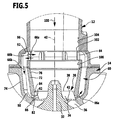
- a flow diversion channel 60 extending in both the impeller housing 14 and the inlet housing 12 is provided, which is arranged around a portion of the inlet channel 22 and around a portion of the impeller 24 in each case radially around the latter and, as in Fig. 3 shown extending from an impeller side opening 62 to an inlet side opening 64, wherein in the flow diversion channel 60, a bypass volumetric flow 66 is formed, the direction and size of which depends on the pressure difference between the impeller side opening 62 and the inlet side opening 64.
- the turbo-compressor operated with a gas flow rate 58, which is lower than the gas volume flow 58 at the design point A, that is, at partial load, so occurs at the impeller side opening 62 of the flow bypass channel 60, a higher pressure than it is present at the inlet side opening 64 and thus A bypass flow 66a is formed through the flow bypass passage 60 so that the bypass flow 66a flows from the impeller side opening 62 to the inlet side opening 64 and passes therethrough to enter the inlet passage 22.
- the flow diversion channel 60 is thereby limited by a radially inner wall 72 of the impeller housing 14 and the inlet housing 12 with respect to the impeller axis 40 and a radially outer wall 74 of the impeller housing 14 and the inlet housing 12, wherein the radially inner wall 72 at the same time an end portion 76 of the Inlet duct 22 forms, which merges into the impeller 24.
- the end section 76 preferably lies between the inlet-side opening 64 of the flow-diversion channel 60 and the hub body 32 of the impeller 30.
- the end portion 76 of the inlet channel 22 is in the region of a plane E1, which is perpendicular to the impeller axis 40 and the hub body 32 touches at its inlet-side upper portion 78, in the impeller passage 24 via.
- end portion 76 preferably lies between the inlet-side opening 64 of the flow-bypass channel 60 and the plane E1 and has a flow-guiding surface 78, which merges smoothly into a surface 80 in which the inlet-side opening 64 lies.
- the inlet channel 22 comprises a flow guide surface 81 of the up to the inlet-side opening 64 of the flow diversion channel 60 is guided.
- the impeller-side opening 62 of the flow diversion channel 60 arranged in the radially inner wall 72 lies in a surface 82 which continuously merges into a flow guide surface 84 of the impeller channel 24 adjoining the impeller-side opening 62 and the flow guide surface 86 of the impeller channel 24 adjoining downstream.
- impeller side opening 62 is disposed so as to lie in the direction of the impeller shaft 40 between the inlet side end 38 of the long impeller blades 34 and the inlet side end 42 of the shorter impeller blades 36 (FIG. Fig. 5 ).
- the impeller side opening 62 is provided in the above-mentioned area to provide the possibility, which is at a gas flow rate lower than the gas volume flow at the design point A, these forming vortex not to flow through the impeller passage 24, but laterally the impeller passage 24 radially to the rotor axis 40 exit.
- Such a bypass volumetric flow 66a occurs when the pressure at the impeller side opening 62 is greater than at the inlet side opening 64, so that due to the pressure difference in the inlet channel 22 entering gas volume flow 58 enters a part as bypass flow 66a in the impeller side opening 62 and over the flow bypass passage 60 flows into the inlet side opening 64.
- the inlet-side opening 64 is in particular arranged such that it lies in a geometrical surface 102 which is continuously adjacent to an upstream surface 104 and a downstream surface 106 and thus does not cause a gas volume flow 58 entering the inlet duct 22.
- surfaces 102, 104, and 106 are cylindrical surfaces that are coaxial with impeller axis 40.
- bypass volumetric flow 66a in particular in operating states with lower gas volume flows 58 than provided for the design point, is favored by the arrangement of the inlet-side openings 64 of the flow diversion channel 60, since the gas volume flow 58 entering via the inlet channel 22 is enhanced by the arrangement of the inlet-side opening 64 in FIG the coaxial to the impeller axis 40 cylindrical surface 80 causes no congestion and thus no increase in pressure in the inlet-side opening 64, so that in the region of the inlet-side opening 64, the bypass flow 66 counteracting effects occur.
- bypass volumetric flow 66a passes through the inlet-side opening 64 with a flow direction 96 that extends transversely to the impeller axis 40 causes this bypass volumetric flow 66a to be mixed with the gas volumetric flow 58 entering through the inlet channel 22, so that the two together enter the impeller duct 24 enter, possibly even accelerated by the narrowing in its cross-section end portion 76 of the inlet channel 22nd
- bypass flow 66a is further facilitated by the flow bypass passage 60 at its inlet side opening 64 provides a flow cross sectional area which is more than 2.5 times the flow cross section of the impeller side opening 62 and in that also Flow diversion channel 60 from the impeller side opening 62 to the inlet side opening 64 is steadily increased.
- deceleration of the bypass volumetric flow 66a as it flows through the flow bypass passage 60 from the impeller side opening 62 to the inlet side opening 64 occurs such that the flow rate of the bypass volumetric flow 66a exiting from the inlet side port 64 is approximately equal to the flow rate of the gas volumetric flow entering the inlet duct 22.
- Such a design of the flow diversion channel 60 causes the turbocompressor starting from the in Fig. 4 shown in part-load operation can still be operated at a gas flow rate 58, which is significantly below the design point A.
- the compressor without a pump that is vibrations by flow instabilities in the gas flow occurs, can be operated up to a gas flow rate, which is up to 60% below the design for the design point A provided gas flow.
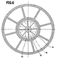
- the flow redirecting channel 60 is divided in the direction of rotation 110 by ribs 112 extending in radial planes 111 to the rotor axis 40, such that the flow redirecting channel 60 is characterized by a sum in the circumferential direction 110 successive channel segments 114 is formed, which are closed on both sides by the ribs 112, whereby the bypass flow 66a in the region of the inlet-side opening 64 with its flow direction 96 has substantially no component in the circumferential direction 110 and thus substantially transverse to the impeller axis 40, in particular approximately radially to this, enters the inlet channel 22.
- the turbocompressor according to the invention can also, as in Fig. 4 shown, operated in the overload range at gas flow rates that are above the design point A, in these cases, with increasing relative to the design point A larger gas flow 58, the pressure at the impeller side opening 62 is lower and thus raises a pressure difference between the impeller-side opening 62 and Inlet-side opening 64, which causes the flow bypass passage 60 is flowed through by a bypass flow stream 66 b, which flows from the inlet-side opening 64 to the impeller-side opening 62, that is branched from the gas volume flow 58 entering through the inlet channel 22 in the region of the inlet-side opening 64 is flowed through the flow diversion channel 60 and enters via the impeller-side opening 62 in the impeller 24 and there is further compressed by the impeller 30.
- bypass volumetric flow 66 b is not favored by the orientation of the inlet-side opening 64, but rather obstructed, since such a bypass volumetric flow 66 b transverse to the impeller axis 40 must leave the inlet channel 22 in the region of the inlet-side opening 64 to enter the flow diversion channel 60.
- turbocompressor according to the invention at the design point A is designed so that there is no pressure difference at this between the inlet-side opening 64 and the impeller-side opening 62, so that no diversion volume flow 66 is formed.
- a diversion volume flow 66a begins with reducing the gas flow rate 58, based on the gas flow rate 58 at the design point slowly and increases with increasing reduction of the gas flow rate 58, so that the turbo-compressor can still be operated at a gas flow rate 58 without pumping at Values of 40% of the gas flow rate 58 at the operating point A.
- approximately 30% of the incoming gas flow rate 58 is recirculated from the impeller side opening 62 to the inlet side opening 64 by the bypass flow rate, and supplied again to the impeller 30.
- the flow diversion channel 60 is assigned a closure unit 120, which is designed as a flutter valve 122.
- the flutter valve 122 includes a fin member 124 held in the inlet housing 12, with the fin member 124 closing the flow redirecting passage 60 (drawn solid) if a bypass volumetric flow 66b would occur due to the pressure difference so that a bypass volumetric flow 66b can not occur.
- the fin element 124 opens and permits such a bypass flow 66a (drawn in dashed lines).
- the closure unit 120 in a third, not the claim 1 underfalfenden example, shown in the Fig. 12 and 13 , the closure unit 120 'comprises two superposed closure rings 132 and 134, each of which has a plurality of ring segments, wherein closure segments 136 and aperture segments 138 alternate with one another.
- the locking rings 132, 134 may be rotated relative to each other, for example, by rotating the locking ring 134 so that the locking segments 136 of one locking ring 134 cover the aperture segments 138 of the other locking ring 132 or are rotated relative to each other such that the locking segments 136 and the aperture segments 138 of both locking rings 132, 134 lie one above the other, so that a bypass flow 66 can pass through the superposed breakthrough segments.
- a diverting volume flow 66a will be permitted in partial load operation and a diversion flow 66b will be prevented in operation near design point A or above design point A.
- the position of the closure ring 134 relative to the closure ring 132 with a controller 140 and an actuator 142 is controllable, so that, for example, depending on the controller 140, for example via sensors detected pressure difference between the inlet side opening 64 and the impeller side opening 62, a control of the bypass flow 66 also can still be done in terms of its strength according to the pressure and flow conditions and flow instabilities and optionally the speed of the impeller.
- FIG. 14 and 15 In a fourth example of a turbocompressor according to the invention, not covered by claim 1, shown in FIG Fig. 14 and 15 , is in the inlet housing 12, for example, guided to the cylindrical surface 104, a sliding sleeve 150 as a closure unit 120 "is provided, which - as in Fig. 14 is movable from the inlet side opening 64 toward the impeller 30 to release the inlet side opening 64, or is movable toward the impeller 30 to successively close the inlet side opening 64, the position closing the inlet side opening 64 in Fig. 15 is shown.
- the sliding sleeve 150 is also preferably controllable by the actuator 142 'and the controller 140' as a function of pressure and flow conditions in turbocompressors, as described in connection with the third embodiment.
Landscapes
- Engineering & Computer Science (AREA)
- Mechanical Engineering (AREA)
- General Engineering & Computer Science (AREA)
- Life Sciences & Earth Sciences (AREA)
- Sustainable Development (AREA)
- Structures Of Non-Positive Displacement Pumps (AREA)
Claims (15)
- Turbocompresseur, comprenant un carter de compresseur (10) dans lequel un flux volumique gazeux entrant est conduit vers un canal (24) de rotor par un canal d'admission (22), est comprimé par un rotor (30) dans le canal (24) de rotor et est évacué du canal (24) de rotor par un canal d'échappement (26), et avec un canal de déviation de flux (60) prévu dans le carter de compresseur (10) et s'étendant en dehors du canal (24) de rotor et du canal d'admission (22), débouchant dans le canal d'admission (22) par une ouverture (64) côté admission, et dans le canal (24) de rotor par une ouverture (62) côté rotor, et conduisant un flux volumique de déviation (66) en fonction d'un différentiel de pression entre les ouvertures, le canal de déviation de flux (60) présentant une section transversale de flux ayant une surface croissante de l'ouverture (62) côté rotor jusqu'à l'ouverture (64) côté entrée,
caractérisé en ce que le canal de déviation de flux (60) peut être fermé par une unité de fermeture (120) comprenant un élément de soupape (124) sollicité par un ressort, pour l'arrêt d'un flux volumique de déviation (66b) entre l'ouverture (64) côté admission et l'ouverture (62) côté sortie. - Turbocompresseur selon la revendication 1, caractérisé en ce que le canal de déviation de flux (60) est constitué de segments (114) de canal juxtaposés dans un sens de rotation (110) par rapport à un axe (40) de rotor.
- Turbocompresseur selon la revendication 2, caractérisé en ce que les segments (114) de canal sont séparés l'un de l'autre dans le sens de rotation (110).
- Turbocompresseur selon la revendication 2 ou 3, caractérisé en ce que les segments (114) de canal sont séparés l'un de l'autre par des traverses (112) s'étendant sur des plans radiaux (111) à l'axe (40) du rotor.
- Turbocompresseur selon l'une des revendications précédentes, caractérisé en ce que l'ouverture (62) côté rotor du canal de déviation de flux (60) est située dans une zone du canal (24) de rotor où se déplacent les aubes (34, 36) du rotor.
- Turbocompresseur selon l'une des revendications précédentes, caractérisé en ce que l'ouverture (62) côté rotor du canal de déviation de flux (60) est située dans la zone entre des extrémités (38) côté admission d'aubes (34) de rotor longues et des extrémités (42) côté admission d'aubes (36) de rotor courtes, les extrémités côté admission des aubes (34) de rotor longues s'étendant parallèlement à l'axe (40) du rotor, plus en amont vers le canal d'admission (22) que les extrémités (42) côté admission des aubes (36) de rotor courtes.
- Turbocompresseur selon l'une des revendications précédentes, caractérisé en ce que l'ouverture (62) côté rotor du canal de déviation de flux (60) est située sur une surface (82) s'étendant de manière continue vers une surface de guidage (84) de flux en amont de ladite ouverture (62) et une surface de guidage (86) de flux en aval de ladite ouverture (62).
- Turbocompresseur selon l'une des revendications précédentes, caractérisé en ce que l'ouverture (62) côté rotor du canal de déviation de flux (60) est formée d'une manière continue dans un sens de rotation (110) autour de l'axe (40) du rotor.
- Turbocompresseur selon l'une des revendications précédentes, caractérisé en ce que l'ouverture (64) côté admission du canal de déviation de flux (60) est située en amont du rotor (30).
- Turbocompresseur selon l'une des revendications précédentes, caractérisé en ce que l'ouverture (64) côté admission du canal de déviation de flux (60) est située sur une surface (80) s'étendant sensiblement parallèlement à une direction d'écoulement (100) du flux volumique gazeux (58) dans le canal d'admission (22).
- Turbocompresseur selon l'une des revendications précédentes, caractérisé en ce que l'ouverture (64) côté admission du canal de déviation de flux (60) est formée de manière périphérique par rapport à un axe (40) du rotor.
- Turbocompresseur selon l'une des revendications précédentes, caractérisé en ce qu'au niveau de l'ouverture (64) côté admission, le canal de déviation de flux (60) dévie un flux volumique de déviation (66a) provenant de l'ouverture (62) côté rotor, de sorte que celui-ci sorte dans le canal d'admission (22) avec une direction d'écoulement (96) transversale à la direction d'écoulement (100) du flux volumique gazeux (58) entrant.
- Turbocompresseur selon l'une des revendications précédentes, caractérisé en ce que le canal de déviation de flux (60) est configuré de manière à favoriser en mode de service à charge partielle un flux volumique de déviation (66a) allant de l'ouverture (62) côté rotor à l'ouverture (64) côté admission.
- Turbocompresseur selon la revendication 13, caractérisé en ce que le canal de déviation de flux (60) est réalisé de manière à pouvoir acheminer plus de 20 % du flux volumique gazeux (58) sollicitant le rotor (30) en mode de service à charge partielle.
- Turbocompresseur selon l'une des revendications précédentes, caractérisé en ce que le canal de déviation de flux (60) permet un mode de service à charge partielle du turbocompresseur pour des flux volumiques gazeux (58) compris entre 40 % du flux volumique gazeux (58) prévu au point de débit nominal (A) et le flux volumique gazeux (58) au point de débit nominal (A).
Applications Claiming Priority (2)
| Application Number | Priority Date | Filing Date | Title |
|---|---|---|---|
| DE102009054771A DE102009054771A1 (de) | 2009-12-16 | 2009-12-16 | Turboverdichter |
| PCT/EP2010/069320 WO2011082942A2 (fr) | 2009-12-16 | 2010-12-09 | Turbocompresseur |
Publications (2)
| Publication Number | Publication Date |
|---|---|
| EP2513488A2 EP2513488A2 (fr) | 2012-10-24 |
| EP2513488B1 true EP2513488B1 (fr) | 2016-07-20 |
Family
ID=43778431
Family Applications (1)
| Application Number | Title | Priority Date | Filing Date |
|---|---|---|---|
| EP10795284.8A Active EP2513488B1 (fr) | 2009-12-16 | 2010-12-09 | Turbocompresseur |
Country Status (5)
| Country | Link |
|---|---|
| US (1) | US8926264B2 (fr) |
| EP (1) | EP2513488B1 (fr) |
| CN (1) | CN102695881B (fr) |
| DE (1) | DE102009054771A1 (fr) |
| WO (1) | WO2011082942A2 (fr) |
Families Citing this family (13)
| Publication number | Priority date | Publication date | Assignee | Title |
|---|---|---|---|---|
| DE102009054771A1 (de) * | 2009-12-16 | 2011-06-22 | Piller Industrieventilatoren GmbH, 37186 | Turboverdichter |
| US9377030B2 (en) * | 2013-03-29 | 2016-06-28 | Honeywell International Inc. | Auxiliary power units and other turbomachines having ported impeller shroud recirculation systems |
| US10107297B2 (en) | 2016-02-04 | 2018-10-23 | General Electric Company | Methods and system for a turbocharger |
| US10309417B2 (en) | 2017-05-12 | 2019-06-04 | Borgwarner Inc. | Turbocharger having improved ported shroud compressor housing |
| US10316859B2 (en) | 2017-05-12 | 2019-06-11 | Borgwarner Inc. | Turbocharger having improved ported shroud compressor housing |
| DE102017221717A1 (de) | 2017-12-01 | 2019-06-06 | Man Energy Solutions Se | Radialverdichter |
| US10578048B2 (en) * | 2018-01-15 | 2020-03-03 | Ford Global Technologies, Llc | Wide range active compressor for HP-EGR engine systems |
| CN110360149A (zh) * | 2018-04-10 | 2019-10-22 | 南通大通宝富风机有限公司 | 叶轮及使用该叶轮的蒸汽压缩设备 |
| CN110118200A (zh) * | 2019-06-14 | 2019-08-13 | 东风汽车集团有限公司 | 压气机壳体及压气机 |
| DE102019212325A1 (de) * | 2019-08-17 | 2021-02-18 | Ziehl-Abegg Se | Verfahren zur quantitativen Bestimmung einer aktuellen betriebszustandsabhängigen Größe eines Ventilators, insbesondere einer Druckänderung oder Druckerhöhung, und Ventilator |
| DE102019133244A1 (de) * | 2019-12-05 | 2021-06-10 | Efficient Energy Gmbh | Wärmepumpe mit stabilitätsverbessertem verdichter |
| CN110973985A (zh) * | 2019-12-19 | 2020-04-10 | 珠海格力电器股份有限公司 | 一种蒸烤箱 |
| CN111140896A (zh) * | 2020-01-20 | 2020-05-12 | 珠海格力电器股份有限公司 | 一种排气装置和吸油烟机 |
Family Cites Families (38)
| Publication number | Priority date | Publication date | Assignee | Title |
|---|---|---|---|---|
| US2342219A (en) * | 1940-03-15 | 1944-02-22 | Lockheed Aircraft Corp | Centrifugal supercharger |
| US2934138A (en) * | 1958-01-06 | 1960-04-26 | Lucas Industries Ltd | Means for controlling the supply of liquid fuel to a gas turbine |
| JPS56167813A (en) * | 1980-05-28 | 1981-12-23 | Nissan Motor Co Ltd | Surge preventing apparatus for turbocharger |
| US4930979A (en) * | 1985-12-24 | 1990-06-05 | Cummins Engine Company, Inc. | Compressors |
| DE3670347D1 (de) * | 1985-12-24 | 1990-05-17 | Holset Engineering Co | Kompressoren. |
| CH675279A5 (fr) * | 1988-06-29 | 1990-09-14 | Asea Brown Boveri | |
| JPH03105096A (ja) * | 1989-09-18 | 1991-05-01 | Hitachi Ltd | 圧縮機の容量制御装置 |
| US5246335A (en) * | 1991-05-01 | 1993-09-21 | Ishikawajima-Harimas Jukogyo Kabushiki Kaisha | Compressor casing for turbocharger and assembly thereof |
| DE19651498C1 (de) * | 1996-12-11 | 1998-04-16 | Daimler Benz Ag | Abgasturboladerturbine für eine Brennkraftmaschine |
| GB9722916D0 (en) | 1997-10-31 | 1998-01-07 | Holset Engineering Co | Compressor |
| DE19823274C1 (de) * | 1998-05-26 | 1999-10-14 | Daimler Chrysler Ag | Abgasturbolader für eine Brennkraftmaschine |
| GB9918072D0 (en) * | 1999-07-30 | 1999-10-06 | Alliedsignal Ltd | Turbocharger |
| DE10049198A1 (de) * | 2000-10-05 | 2002-04-11 | Daimler Chrysler Ag | Abgasturbolader für eine Brennkraftmaschine und Verfahren hierzu |
| US6623239B2 (en) * | 2000-12-13 | 2003-09-23 | Honeywell International Inc. | Turbocharger noise deflector |
| WO2002103209A1 (fr) * | 2001-06-15 | 2002-12-27 | Concepts Eti, Inc. | Dispositif de stabilisation d'ecoulement |
| KR100455419B1 (ko) * | 2002-03-14 | 2004-11-06 | 주식회사 엘지이아이 | 스크롤 압축기의 소음 저감 장치 |
| EP1473465B2 (fr) * | 2003-04-30 | 2018-08-01 | Holset Engineering Company Limited | Compresseur |
| DE602004001908T2 (de) * | 2003-04-30 | 2007-04-26 | Holset Engineering Co. Ltd., Huddersfield | Kompressor |
| US7025557B2 (en) | 2004-01-14 | 2006-04-11 | Concepts Eti, Inc. | Secondary flow control system |
| US6945748B2 (en) * | 2004-01-22 | 2005-09-20 | Electro-Motive Diesel, Inc. | Centrifugal compressor with channel ring defined inlet recirculation channel |
| DE102004003209A1 (de) * | 2004-01-22 | 2005-08-11 | Daimlerchrysler Ag | Verdichter im Ansaugtrakt einer Brennkraftmaschine |
| DE102004027594B4 (de) * | 2004-06-05 | 2006-06-29 | Man B & W Diesel Ag | Strömungsmaschine mit radial durchströmtem Verdichterrad |
| DE602004015337D1 (de) * | 2004-06-07 | 2008-09-04 | Honeywell Int Inc | Verdichter mit rückführung und verfahren |
| JP2006002650A (ja) | 2004-06-17 | 2006-01-05 | Toyota Motor Corp | 入口ベーンとバイパス制御弁とを連動させた遠心圧縮機 |
| DE102005019939A1 (de) * | 2005-04-29 | 2006-11-09 | Daimlerchrysler Ag | Verdichter im Ansaugtrakt einer Brennkraftmaschine |
| DE102006007347A1 (de) * | 2006-02-17 | 2007-08-30 | Daimlerchrysler Ag | Verdichter für eine Brennkraftmaschine |
| US7698894B2 (en) * | 2006-05-22 | 2010-04-20 | International Engine Intellectual Property Company, Llc | Engine intake air compressor and method |
| US7475539B2 (en) * | 2006-05-24 | 2009-01-13 | Honeywell International, Inc. | Inclined rib ported shroud compressor housing |
| US7942625B2 (en) * | 2007-04-04 | 2011-05-17 | Honeywell International, Inc. | Compressor and compressor housing |
| DE102007035966A1 (de) * | 2007-07-30 | 2009-02-05 | Bosch Mahle Turbosystems Gmbh & Co. Kg | Radialverdichter für einen Turbolader |
| JP5351401B2 (ja) * | 2007-09-28 | 2013-11-27 | 三菱重工業株式会社 | 圧縮機 |
| JP5039673B2 (ja) * | 2008-02-27 | 2012-10-03 | 三菱重工業株式会社 | ターボ型圧縮機のストラット構造 |
| US8272832B2 (en) * | 2008-04-17 | 2012-09-25 | Honeywell International Inc. | Centrifugal compressor with surge control, and associated method |
| US8061974B2 (en) * | 2008-09-11 | 2011-11-22 | Honeywell International Inc. | Compressor with variable-geometry ported shroud |
| DE102008047506A1 (de) * | 2008-09-17 | 2010-04-15 | Daimler Ag | Radialverdichter, insbesondere für einen Abgasturbolader einer Brennkraftmaschine |
| DE102009054773A1 (de) * | 2009-12-16 | 2011-06-22 | Piller Industrieventilatoren GmbH, 37186 | Turboverdichter und Verdichteranlage umfassend einen derartigen Turboverdichter |
| DE102009054771A1 (de) * | 2009-12-16 | 2011-06-22 | Piller Industrieventilatoren GmbH, 37186 | Turboverdichter |
| US8517664B2 (en) * | 2010-01-19 | 2013-08-27 | Ford Global Technologies, Llc | Turbocharger |
-
2009
- 2009-12-16 DE DE102009054771A patent/DE102009054771A1/de not_active Withdrawn
-
2010
- 2010-12-09 WO PCT/EP2010/069320 patent/WO2011082942A2/fr not_active Ceased
- 2010-12-09 EP EP10795284.8A patent/EP2513488B1/fr active Active
- 2010-12-09 CN CN201080057550.7A patent/CN102695881B/zh active Active
-
2012
- 2012-06-14 US US13/523,507 patent/US8926264B2/en active Active
Also Published As
| Publication number | Publication date |
|---|---|
| WO2011082942A3 (fr) | 2011-12-01 |
| EP2513488A2 (fr) | 2012-10-24 |
| CN102695881A (zh) | 2012-09-26 |
| WO2011082942A2 (fr) | 2011-07-14 |
| US20130058762A1 (en) | 2013-03-07 |
| CN102695881B (zh) | 2016-03-09 |
| DE102009054771A1 (de) | 2011-06-22 |
| US8926264B2 (en) | 2015-01-06 |
| HK1171491A1 (zh) | 2013-03-28 |
Similar Documents
| Publication | Publication Date | Title |
|---|---|---|
| EP2513488B1 (fr) | Turbocompresseur | |
| DE69114647T2 (de) | Axialströmungsgebläse. | |
| EP3009683B1 (fr) | Systeme et procede pour prélèvement d'air de compresseur d'un propulseur | |
| DE1551182A1 (de) | Stroemungsmittelsteuerung fuer Reaktionsturbinen ohne Leitschaufelkranz | |
| EP2499375B1 (fr) | Fond intermédiaire pour une turbomachine radiale | |
| EP2881548B1 (fr) | Compresseur de turbine à gaz | |
| DE1751838C3 (de) | Brennkammer für Gasturbinenanlagen mit einer Strömungssteuereinrichtung | |
| EP3032032B1 (fr) | Aubes directrices de sortie et turboréacteur à double flux avec des aubes directrices de sortie | |
| DE102015111746A1 (de) | Gekühltes Turbinenlaufrad, insbesondere für ein Flugtriebwerk | |
| EP1789653B1 (fr) | Rotor pour un propulseur | |
| EP1870203A1 (fr) | Machine-outil dotée d'un capot d'aspiration | |
| WO2018166716A1 (fr) | Étage de retour et turbomachine à énergie fluidique radiale | |
| DE102016207212A1 (de) | Leitschaufelkranz für eine Strömungsmaschine | |
| DE3430769C2 (fr) | ||
| EP0439757B1 (fr) | Moyen de contrôle de la prérotation pour un compresseur radial à grande capacité | |
| EP3561228A1 (fr) | Aube, segment d'aube et module pour une turbomachine et turbomachine | |
| EP2342464B1 (fr) | Ventilateur à canal latéral, en particulier turbine secondaire pour un moteur à combustion interne | |
| DE102016208265A1 (de) | Rückführstufe, Radialturboverdichter | |
| EP1122444A2 (fr) | Ventilateur radial et buse pour ventilateur radial | |
| EP0979354A1 (fr) | Pompe regenerative presentant un canal lateral dans le couvercle d'aspiration pour eviter des structures tourbillonnaires a pertes importantes | |
| EP3719258B1 (fr) | Aube mobile d'une turbomachine | |
| DE3221465C2 (de) | Eintrittsleitbeschaufelung | |
| EP4296489B1 (fr) | Entrée d'air | |
| DE3022206C2 (de) | Axialverdichter mit verschobener Pumpgrenze | |
| DE1503532B2 (de) | Querdurchströmtes Gebläse |
Legal Events
| Date | Code | Title | Description |
|---|---|---|---|
| PUAI | Public reference made under article 153(3) epc to a published international application that has entered the european phase |
Free format text: ORIGINAL CODE: 0009012 |
|
| 17P | Request for examination filed |
Effective date: 20120613 |
|
| AK | Designated contracting states |
Kind code of ref document: A2 Designated state(s): AL AT BE BG CH CY CZ DE DK EE ES FI FR GB GR HR HU IE IS IT LI LT LU LV MC MK MT NL NO PL PT RO RS SE SI SK SM TR |
|
| DAX | Request for extension of the european patent (deleted) | ||
| RAP1 | Party data changed (applicant data changed or rights of an application transferred) |
Owner name: PILLER BLOWERS & COMPRESSORS GMBH |
|
| GRAP | Despatch of communication of intention to grant a patent |
Free format text: ORIGINAL CODE: EPIDOSNIGR1 |
|
| INTG | Intention to grant announced |
Effective date: 20160201 |
|
| GRAS | Grant fee paid |
Free format text: ORIGINAL CODE: EPIDOSNIGR3 |
|
| GRAA | (expected) grant |
Free format text: ORIGINAL CODE: 0009210 |
|
| AK | Designated contracting states |
Kind code of ref document: B1 Designated state(s): AL AT BE BG CH CY CZ DE DK EE ES FI FR GB GR HR HU IE IS IT LI LT LU LV MC MK MT NL NO PL PT RO RS SE SI SK SM TR |
|
| REG | Reference to a national code |
Ref country code: GB Ref legal event code: FG4D Free format text: NOT ENGLISH |
|
| REG | Reference to a national code |
Ref country code: CH Ref legal event code: EP |
|
| REG | Reference to a national code |
Ref country code: IE Ref legal event code: FG4D Free format text: LANGUAGE OF EP DOCUMENT: GERMAN |
|
| REG | Reference to a national code |
Ref country code: AT Ref legal event code: REF Ref document number: 814340 Country of ref document: AT Kind code of ref document: T Effective date: 20160815 |
|
| REG | Reference to a national code |
Ref country code: DE Ref legal event code: R096 Ref document number: 502010012061 Country of ref document: DE |
|
| REG | Reference to a national code |
Ref country code: LT Ref legal event code: MG4D |
|
| REG | Reference to a national code |
Ref country code: NL Ref legal event code: MP Effective date: 20160720 |
|
| PG25 | Lapsed in a contracting state [announced via postgrant information from national office to epo] |
Ref country code: NO Free format text: LAPSE BECAUSE OF FAILURE TO SUBMIT A TRANSLATION OF THE DESCRIPTION OR TO PAY THE FEE WITHIN THE PRESCRIBED TIME-LIMIT Effective date: 20161020 Ref country code: LT Free format text: LAPSE BECAUSE OF FAILURE TO SUBMIT A TRANSLATION OF THE DESCRIPTION OR TO PAY THE FEE WITHIN THE PRESCRIBED TIME-LIMIT Effective date: 20160720 Ref country code: NL Free format text: LAPSE BECAUSE OF FAILURE TO SUBMIT A TRANSLATION OF THE DESCRIPTION OR TO PAY THE FEE WITHIN THE PRESCRIBED TIME-LIMIT Effective date: 20160720 Ref country code: FI Free format text: LAPSE BECAUSE OF FAILURE TO SUBMIT A TRANSLATION OF THE DESCRIPTION OR TO PAY THE FEE WITHIN THE PRESCRIBED TIME-LIMIT Effective date: 20160720 Ref country code: RS Free format text: LAPSE BECAUSE OF FAILURE TO SUBMIT A TRANSLATION OF THE DESCRIPTION OR TO PAY THE FEE WITHIN THE PRESCRIBED TIME-LIMIT Effective date: 20160720 Ref country code: HR Free format text: LAPSE BECAUSE OF FAILURE TO SUBMIT A TRANSLATION OF THE DESCRIPTION OR TO PAY THE FEE WITHIN THE PRESCRIBED TIME-LIMIT Effective date: 20160720 Ref country code: IS Free format text: LAPSE BECAUSE OF FAILURE TO SUBMIT A TRANSLATION OF THE DESCRIPTION OR TO PAY THE FEE WITHIN THE PRESCRIBED TIME-LIMIT Effective date: 20161120 Ref country code: IT Free format text: LAPSE BECAUSE OF FAILURE TO SUBMIT A TRANSLATION OF THE DESCRIPTION OR TO PAY THE FEE WITHIN THE PRESCRIBED TIME-LIMIT Effective date: 20160720 |
|
| PG25 | Lapsed in a contracting state [announced via postgrant information from national office to epo] |
Ref country code: ES Free format text: LAPSE BECAUSE OF FAILURE TO SUBMIT A TRANSLATION OF THE DESCRIPTION OR TO PAY THE FEE WITHIN THE PRESCRIBED TIME-LIMIT Effective date: 20160720 Ref country code: PT Free format text: LAPSE BECAUSE OF FAILURE TO SUBMIT A TRANSLATION OF THE DESCRIPTION OR TO PAY THE FEE WITHIN THE PRESCRIBED TIME-LIMIT Effective date: 20161121 Ref country code: LV Free format text: LAPSE BECAUSE OF FAILURE TO SUBMIT A TRANSLATION OF THE DESCRIPTION OR TO PAY THE FEE WITHIN THE PRESCRIBED TIME-LIMIT Effective date: 20160720 Ref country code: PL Free format text: LAPSE BECAUSE OF FAILURE TO SUBMIT A TRANSLATION OF THE DESCRIPTION OR TO PAY THE FEE WITHIN THE PRESCRIBED TIME-LIMIT Effective date: 20160720 Ref country code: GR Free format text: LAPSE BECAUSE OF FAILURE TO SUBMIT A TRANSLATION OF THE DESCRIPTION OR TO PAY THE FEE WITHIN THE PRESCRIBED TIME-LIMIT Effective date: 20161021 Ref country code: SE Free format text: LAPSE BECAUSE OF FAILURE TO SUBMIT A TRANSLATION OF THE DESCRIPTION OR TO PAY THE FEE WITHIN THE PRESCRIBED TIME-LIMIT Effective date: 20160720 |
|
| REG | Reference to a national code |
Ref country code: DE Ref legal event code: R097 Ref document number: 502010012061 Country of ref document: DE |
|
| PG25 | Lapsed in a contracting state [announced via postgrant information from national office to epo] |
Ref country code: EE Free format text: LAPSE BECAUSE OF FAILURE TO SUBMIT A TRANSLATION OF THE DESCRIPTION OR TO PAY THE FEE WITHIN THE PRESCRIBED TIME-LIMIT Effective date: 20160720 Ref country code: RO Free format text: LAPSE BECAUSE OF FAILURE TO SUBMIT A TRANSLATION OF THE DESCRIPTION OR TO PAY THE FEE WITHIN THE PRESCRIBED TIME-LIMIT Effective date: 20160720 |
|
| PLBE | No opposition filed within time limit |
Free format text: ORIGINAL CODE: 0009261 |
|
| STAA | Information on the status of an ep patent application or granted ep patent |
Free format text: STATUS: NO OPPOSITION FILED WITHIN TIME LIMIT |
|
| PG25 | Lapsed in a contracting state [announced via postgrant information from national office to epo] |
Ref country code: BE Free format text: LAPSE BECAUSE OF NON-PAYMENT OF DUE FEES Effective date: 20161231 Ref country code: DK Free format text: LAPSE BECAUSE OF FAILURE TO SUBMIT A TRANSLATION OF THE DESCRIPTION OR TO PAY THE FEE WITHIN THE PRESCRIBED TIME-LIMIT Effective date: 20160720 Ref country code: SK Free format text: LAPSE BECAUSE OF FAILURE TO SUBMIT A TRANSLATION OF THE DESCRIPTION OR TO PAY THE FEE WITHIN THE PRESCRIBED TIME-LIMIT Effective date: 20160720 Ref country code: BG Free format text: LAPSE BECAUSE OF FAILURE TO SUBMIT A TRANSLATION OF THE DESCRIPTION OR TO PAY THE FEE WITHIN THE PRESCRIBED TIME-LIMIT Effective date: 20161020 Ref country code: CZ Free format text: LAPSE BECAUSE OF FAILURE TO SUBMIT A TRANSLATION OF THE DESCRIPTION OR TO PAY THE FEE WITHIN THE PRESCRIBED TIME-LIMIT Effective date: 20160720 Ref country code: SM Free format text: LAPSE BECAUSE OF FAILURE TO SUBMIT A TRANSLATION OF THE DESCRIPTION OR TO PAY THE FEE WITHIN THE PRESCRIBED TIME-LIMIT Effective date: 20160720 |
|
| 26N | No opposition filed |
Effective date: 20170421 |
|
| REG | Reference to a national code |
Ref country code: CH Ref legal event code: PL |
|
| GBPC | Gb: european patent ceased through non-payment of renewal fee |
Effective date: 20161209 |
|
| PG25 | Lapsed in a contracting state [announced via postgrant information from national office to epo] |
Ref country code: SI Free format text: LAPSE BECAUSE OF FAILURE TO SUBMIT A TRANSLATION OF THE DESCRIPTION OR TO PAY THE FEE WITHIN THE PRESCRIBED TIME-LIMIT Effective date: 20160720 |
|
| PG25 | Lapsed in a contracting state [announced via postgrant information from national office to epo] |
Ref country code: MC Free format text: LAPSE BECAUSE OF FAILURE TO SUBMIT A TRANSLATION OF THE DESCRIPTION OR TO PAY THE FEE WITHIN THE PRESCRIBED TIME-LIMIT Effective date: 20160720 |
|
| REG | Reference to a national code |
Ref country code: FR Ref legal event code: ST Effective date: 20170831 |
|
| REG | Reference to a national code |
Ref country code: IE Ref legal event code: MM4A |
|
| PG25 | Lapsed in a contracting state [announced via postgrant information from national office to epo] |
Ref country code: LU Free format text: LAPSE BECAUSE OF NON-PAYMENT OF DUE FEES Effective date: 20161209 Ref country code: LI Free format text: LAPSE BECAUSE OF NON-PAYMENT OF DUE FEES Effective date: 20161231 Ref country code: FR Free format text: LAPSE BECAUSE OF NON-PAYMENT OF DUE FEES Effective date: 20170102 Ref country code: CH Free format text: LAPSE BECAUSE OF NON-PAYMENT OF DUE FEES Effective date: 20161231 |
|
| PG25 | Lapsed in a contracting state [announced via postgrant information from national office to epo] |
Ref country code: IE Free format text: LAPSE BECAUSE OF NON-PAYMENT OF DUE FEES Effective date: 20161209 Ref country code: GB Free format text: LAPSE BECAUSE OF NON-PAYMENT OF DUE FEES Effective date: 20161209 |
|
| REG | Reference to a national code |
Ref country code: BE Ref legal event code: MM Effective date: 20161231 |
|
| REG | Reference to a national code |
Ref country code: AT Ref legal event code: MM01 Ref document number: 814340 Country of ref document: AT Kind code of ref document: T Effective date: 20161209 |
|
| PG25 | Lapsed in a contracting state [announced via postgrant information from national office to epo] |
Ref country code: HU Free format text: LAPSE BECAUSE OF FAILURE TO SUBMIT A TRANSLATION OF THE DESCRIPTION OR TO PAY THE FEE WITHIN THE PRESCRIBED TIME-LIMIT; INVALID AB INITIO Effective date: 20101209 Ref country code: AT Free format text: LAPSE BECAUSE OF NON-PAYMENT OF DUE FEES Effective date: 20161209 Ref country code: CY Free format text: LAPSE BECAUSE OF FAILURE TO SUBMIT A TRANSLATION OF THE DESCRIPTION OR TO PAY THE FEE WITHIN THE PRESCRIBED TIME-LIMIT Effective date: 20160720 |
|
| PG25 | Lapsed in a contracting state [announced via postgrant information from national office to epo] |
Ref country code: MK Free format text: LAPSE BECAUSE OF FAILURE TO SUBMIT A TRANSLATION OF THE DESCRIPTION OR TO PAY THE FEE WITHIN THE PRESCRIBED TIME-LIMIT Effective date: 20160720 Ref country code: TR Free format text: LAPSE BECAUSE OF FAILURE TO SUBMIT A TRANSLATION OF THE DESCRIPTION OR TO PAY THE FEE WITHIN THE PRESCRIBED TIME-LIMIT Effective date: 20160720 |
|
| PG25 | Lapsed in a contracting state [announced via postgrant information from national office to epo] |
Ref country code: MT Free format text: LAPSE BECAUSE OF FAILURE TO SUBMIT A TRANSLATION OF THE DESCRIPTION OR TO PAY THE FEE WITHIN THE PRESCRIBED TIME-LIMIT Effective date: 20160720 |
|
| PG25 | Lapsed in a contracting state [announced via postgrant information from national office to epo] |
Ref country code: AL Free format text: LAPSE BECAUSE OF FAILURE TO SUBMIT A TRANSLATION OF THE DESCRIPTION OR TO PAY THE FEE WITHIN THE PRESCRIBED TIME-LIMIT Effective date: 20160720 |
|
| REG | Reference to a national code |
Ref country code: DE Ref legal event code: R082 Ref document number: 502010012061 Country of ref document: DE Representative=s name: HOEGER, STELLRECHT & PARTNER PATENTANWAELTE MB, DE Ref country code: DE Ref legal event code: R081 Ref document number: 502010012061 Country of ref document: DE Owner name: KAESER KOMPRESSOREN SE, DE Free format text: FORMER OWNER: PILLER BLOWERS & COMPRESSORS GMBH, 37186 MORINGEN, DE |
|
| P01 | Opt-out of the competence of the unified patent court (upc) registered |
Effective date: 20230517 |
|
| PGFP | Annual fee paid to national office [announced via postgrant information from national office to epo] |
Ref country code: DE Payment date: 20241217 Year of fee payment: 15 |