EP3009683B1 - Systeme et procede pour prélèvement d'air de compresseur d'un propulseur - Google Patents
Systeme et procede pour prélèvement d'air de compresseur d'un propulseur Download PDFInfo
- Publication number
- EP3009683B1 EP3009683B1 EP15189636.2A EP15189636A EP3009683B1 EP 3009683 B1 EP3009683 B1 EP 3009683B1 EP 15189636 A EP15189636 A EP 15189636A EP 3009683 B1 EP3009683 B1 EP 3009683B1
- Authority
- EP
- European Patent Office
- Prior art keywords
- duct
- blow
- channel
- displaceable
- compressor air
- Prior art date
- Legal status (The legal status is an assumption and is not a legal conclusion. Google has not performed a legal analysis and makes no representation as to the accuracy of the status listed.)
- Not-in-force
Links
Images


Classifications
-
- F—MECHANICAL ENGINEERING; LIGHTING; HEATING; WEAPONS; BLASTING
- F01—MACHINES OR ENGINES IN GENERAL; ENGINE PLANTS IN GENERAL; STEAM ENGINES
- F01D—NON-POSITIVE DISPLACEMENT MACHINES OR ENGINES, e.g. STEAM TURBINES
- F01D17/00—Regulating or controlling by varying flow
- F01D17/10—Final actuators
- F01D17/105—Final actuators by passing part of the fluid
-
- F—MECHANICAL ENGINEERING; LIGHTING; HEATING; WEAPONS; BLASTING
- F02—COMBUSTION ENGINES; HOT-GAS OR COMBUSTION-PRODUCT ENGINE PLANTS
- F02C—GAS-TURBINE PLANTS; AIR INTAKES FOR JET-PROPULSION PLANTS; CONTROLLING FUEL SUPPLY IN AIR-BREATHING JET-PROPULSION PLANTS
- F02C6/00—Plural gas-turbine plants; Combinations of gas-turbine plants with other apparatus; Adaptations of gas-turbine plants for special use
- F02C6/04—Gas-turbine plants providing heated or pressurised working fluid for other apparatus, e.g. without mechanical power output
- F02C6/06—Gas-turbine plants providing heated or pressurised working fluid for other apparatus, e.g. without mechanical power output providing compressed gas
- F02C6/08—Gas-turbine plants providing heated or pressurised working fluid for other apparatus, e.g. without mechanical power output providing compressed gas the gas being bled from the gas-turbine compressor
-
- F—MECHANICAL ENGINEERING; LIGHTING; HEATING; WEAPONS; BLASTING
- F02—COMBUSTION ENGINES; HOT-GAS OR COMBUSTION-PRODUCT ENGINE PLANTS
- F02C—GAS-TURBINE PLANTS; AIR INTAKES FOR JET-PROPULSION PLANTS; CONTROLLING FUEL SUPPLY IN AIR-BREATHING JET-PROPULSION PLANTS
- F02C9/00—Controlling gas-turbine plants; Controlling fuel supply in air- breathing jet-propulsion plants
- F02C9/16—Control of working fluid flow
- F02C9/18—Control of working fluid flow by bleeding, bypassing or acting on variable working fluid interconnections between turbines or compressors or their stages
-
- F—MECHANICAL ENGINEERING; LIGHTING; HEATING; WEAPONS; BLASTING
- F02—COMBUSTION ENGINES; HOT-GAS OR COMBUSTION-PRODUCT ENGINE PLANTS
- F02K—JET-PROPULSION PLANTS
- F02K3/00—Plants including a gas turbine driving a compressor or a ducted fan
- F02K3/02—Plants including a gas turbine driving a compressor or a ducted fan in which part of the working fluid by-passes the turbine and combustion chamber
- F02K3/04—Plants including a gas turbine driving a compressor or a ducted fan in which part of the working fluid by-passes the turbine and combustion chamber the plant including ducted fans, i.e. fans with high volume, low pressure outputs, for augmenting the jet thrust, e.g. of double-flow type
- F02K3/075—Plants including a gas turbine driving a compressor or a ducted fan in which part of the working fluid by-passes the turbine and combustion chamber the plant including ducted fans, i.e. fans with high volume, low pressure outputs, for augmenting the jet thrust, e.g. of double-flow type controlling flow ratio between flows
-
- F—MECHANICAL ENGINEERING; LIGHTING; HEATING; WEAPONS; BLASTING
- F04—POSITIVE - DISPLACEMENT MACHINES FOR LIQUIDS; PUMPS FOR LIQUIDS OR ELASTIC FLUIDS
- F04D—NON-POSITIVE-DISPLACEMENT PUMPS
- F04D27/00—Control, e.g. regulation, of pumps, pumping installations or pumping systems specially adapted for elastic fluids
- F04D27/02—Surge control
- F04D27/0207—Surge control by bleeding, bypassing or recycling fluids
- F04D27/0215—Arrangements therefor, e.g. bleed or by-pass valves
-
- F—MECHANICAL ENGINEERING; LIGHTING; HEATING; WEAPONS; BLASTING
- F04—POSITIVE - DISPLACEMENT MACHINES FOR LIQUIDS; PUMPS FOR LIQUIDS OR ELASTIC FLUIDS
- F04D—NON-POSITIVE-DISPLACEMENT PUMPS
- F04D27/00—Control, e.g. regulation, of pumps, pumping installations or pumping systems specially adapted for elastic fluids
- F04D27/02—Surge control
- F04D27/0207—Surge control by bleeding, bypassing or recycling fluids
- F04D27/023—Details or means for fluid extraction
Definitions
- the invention relates to an arrangement and a method for blowing off compressor air in an engine.
- the solution according to the invention is characterized in that the channel geometry of the Abblasekanals is adjustable.
- the invention is thus based on the idea not to close or partially close a Abblasekanal means of a Verschbooimplantations, but the channel geometry of the Abblasekanals even downstream of an opening through which the compressor air to be discharged enters the Abblasekanal, variable, so that at least a local change can be provided in the geometry of the blow-off channel.
- the changed channel geometry corresponds with a change in the cross-sectional area of the blow-off duct at least in a partial area and thus enables a defined adjustment of the air flow in the blow-off duct.
- the cross-sectional area is thereby formed by the outer boundary surfaces of the blow-off channel, ie by those structures which limit the gas flow to form the blow-off channel on the outside.
- the solution according to the invention does not consider arrangements in which an additional object is introduced into the blow-off channel and possibly reduced by such an object, for the gas flow to the There is available cross-sectional area. Rather, the invention regards a change in the channel geometry itself, ie with respect to the outer boundary surfaces of the blow-off channel, a change in the geometry and an at least local change in the cross-sectional area occur in the event of an adjustment.
- the channel geometry and the flow-through cross-sectional area of the blow-off channel are thus adjustable downstream of an opening, via which the compressor air to be discharged enters the blow-off duct.
- An outer (provided downstream of the opening) boundary surface of the Abblasekanals is here accordingly transversely to the flow direction of the compressor air in at least a portion adjustable to change within the Abblasekanals at least locally its channel geometry and set variable.
- the arrangement comprises means by which the cross-sectional area of the blow-off channel is variable at least in a partial region of the blow-off channel.
- such means are designed such that the cross section of the blow-off channel can be changed continuously. This makes it possible to adjust the mass flow through the blow-off channel continuously.
- the Abblasekanal comprises a displaceable element which forms in a partial region of the Abblasekanals its limitation with respect to the fluid flowing in the Abblasekanal.
- the channel geometry is changed. The channel geometry is changed, for example, to change the minimum cross-sectional area of the blow-off channel.
- the displaceable element can be designed as a displaceable throttle and comprises, for example, a disk-shaped or annular element. It is preferably provided that the displaceable element is convexly formed towards the interior of the blow-off channel forms a continuous transition without discontinuities to adjacent boundary surfaces, so that it is flowed around with the lowest possible flow losses.
- the displaceable element is arranged in a section of the blow-off duct which extends substantially parallel to a bypass duct into which the compressor air is blown off.
- a Parallel to the bypass channel extending portion of the Abblasekanals causes a parallel guidance of the air flow in Abblasekanal and in the bypass duct, which advantageously allows to merge the air streams with low turbulence and accordingly with high efficiency.
- a further embodiment provides that the displaceable element is arranged in a section of the blow-off channel which narrows and / or which is formed bent.
- the displacement of the displaceable element in such a section in or against the flow direction automatically leads to the fact that, depending on the position of the displaceable element, a different minimum cross-sectional area of the blow-off channel is realized.
- a further embodiment of the invention provides that at least one channel segment which delimits the blow-off channel is designed to be adjustable.
- a boundary surface of the blow-off channel is adjusted in its entirety, at least in a partial area, so that the channel geometry changes.
- a channel segment is displaceable substantially transversely to the flow direction in the blow-off.
- a channel segment is displaceable in the axial direction, wherein the axial direction designates the longitudinal extension direction of an engine, in which the arrangement according to the invention is arranged.
- a further embodiment of the invention provides that the blow-off channel is delimited by a plurality of channel segments and at least some of the channel segments are adjustable so that the distance of the channel segments from one another is variable.
- the at least one slidable channel segment forms in one embodiment of the invention a front or a rear axial boundary of the blow-off channel in a region of the blow-off channel in which it extends in a direction comprising a radial component.
- the displaceable channel segment is formed at the downstream end portion of a splitter, which separates the primary flow channel from the bypass duct of the engine.
- the displaceable channel segment is formed by the upstream portion of a housing portion which connects in the axial direction of such a splitter.
- the displaceable channel segment necessarily forms a transition region to stationary housing segments, which are not adjustable.
- a transition region is provided according to an embodiment of the invention by a parallel guide by means of overlapping housing parts on the one hand of the displaceable channel segment and on the other hand of a stationary housing segment.
- a transition region may be e.g. take place by a telescopic guide of the sliding channel segment on the stationary housing segment.
- the proposed means for adjusting the channel geometry is adjusted for example by an actuator which is arranged stationary on the housing side and via mechanical coupling elements such.
- a closing element can additionally be provided for completely closing off the blow-off duct.
- a closing element makes it possible to completely close a blow-off channel, while the adjustability of the channel geometry according to the invention is used to set the mass flow of the air conducted through the blow-off channel in the open state of the closing element.
- the arrangement according to the invention is designed to introduce compressor air from the primary flow duct of a turbofan engine via the blow-off duct into a bypass duct of the turbofan engine.
- the invention also relates to a method for blowing off compressor air in an engine in which compressor air to be blown out of a compressor of the engine is directed into a blow-off duct.
- the method provides that, for adjusting the mass flow of the compressor air to be blown off, the duct geometry of the blow-off duct is changed and the blow-off duct is not closed by means of a closing element.
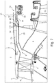
- the FIG. 1 shows components of a turbofan engine.
- the illustrated section of a turbofan engine comprises a bypass duct 2 and a primary flow duct 3 into which air mass drawn in by a fan (not shown) is passed.
- the bypass duct 2 and the primary flow channel 3 are separated from each other behind the fan by a splitter 4.
- the primary flow channel 3 passes through the core engine.
- the core engine comprises a low-pressure compressor 6, a high-pressure compressor, a combustion chamber, a high-pressure turbine and a low-pressure turbine.
- blow-off of compressor air of the low pressure compressor 6 is important. It should be noted, however, that the principles of the invention, which will be explained below with reference to the blow-off of compressor air of a low-pressure compressor, are equally applicable to the discharge of compressor air, e.g. a high-pressure compressor or a medium-pressure compressor (in a three-shaft engine) can be used.
- the low-pressure compressor 6 comprises a compressor stage, which is also referred to as a booster stage. Instead of a compressor stage and several compressor stages can be provided.
- a stator 5 is arranged in the primary flow channel 3, which serves to take swirl from the air flow, this has received in the region of the fan near the hub.
- a stator 91 and support struts 92 are arranged in the bypass duct 2.
- the low-pressure compressor 6 is surrounded by a peripheral housing 8, which limits the primary flow channel 3 radially outward. Radially inside, the primary flow channel 3 is formed by corresponding ring surfaces of the rotors and stators or by the hub or by elements of the corresponding drive shaft connected to the hub.
- the peripheral housing 8 has an opening 9, which opens to a blow-off channel 7.
- the blow-off duct 7 serves to blow off compressor air of the low-pressure compressor 6.
- the blow-off duct 7 blows the compressor air into the bypass duct 2 and accordingly has at its rear end 70 an opening to the bypass duct 2 or alternatively to structures which in turn are connected to the bypass duct 2 ,
- the course of the blow-off 7 is in the FIG. 1 shown only as an example.
- the opening 9 in the primary flow channel 3 to the Abblasekanal 7 may be formed circumferentially or consist of a plurality of evenly distributed on the circumference openings.
- the Abblasekanal 7 may be rotationally symmetrical, but it may be interrupted by structural elements, for example, a structural load receiving intermediate housing (IMC).
- IMC structural load receiving intermediate housing
- the blow-off channel 7 has a channel geometry which is adjustable so that the mass flow of the compressor air blown off through the blow-off duct 7 is also defined Way is adjustable. This will be described below with reference to several variants.
- the blow-off 7 is limited by walls that can be designed in several parts.
- the walls include an axially forward wall 30 and an axially rearward wall 20.
- a displaceable element 11 which is in the Abblasekanal 7 outer boundary surfaces 110 for flowing in the Abblasekanal 7 fluid.
- the boundary surfaces 110 are formed convex, so that the flow flows substantially laminar and without turbulence on the displaceable element 11.
- the displaceable element 11 is located in a portion 72 of the blow-off channel 7, which extends substantially in the axial direction and, accordingly, substantially parallel to the bypass channel 2.
- the blow-off passage 7 adjacent to the opening 9 comprises a portion 71 having a radial component with respect to its extension direction.
- the cross-sectional area in the section 72 of the blow-off channel 7 can be changed, i. H. the area in the cross-sectional view, can be transported through the air to be blown off.
- the displaceable element 11 is displaceable within the section 72 in the flow direction of the blow-off channel 7, ie in the considered embodiment in the axial direction.
- the axial displaceability is provided by an actuator 13 which is stationary and connected to a stationary strut 15 or other fixed housing structure.
- the actuator 13 is connected via a coupling rod 14 or another coupling means with a connecting part 12 which protrudes through a recess, for example a slot (not shown separately) in the one wall 20 and is fixedly connected to the displaceable element 11.
- the wall 20 is adjacent to the displaceable element 11, the outer boundary surface of the one side of the Abblasekanals 7. In the region of the displaceable element 11, the wall 20 on its side facing the Abblasekanal 7 but covered by the displaceable element 11 and provides this with his Surface 110, the outer boundary surface of the one side of the blow-off 7.
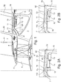
- FIGS. 2A, 2B show by way of example two positions of the displaceable element 11.
- the cross-sectional area in the discharge channel 7 changes in the region of the displaceable element 11. This is due to the fact that the discharge channel 7 converges convergently in the considered section 72, so that the further the displaceable element 11 in the axial direction shifted to the rear, the smaller is the provided for the passage of compressor air cross-sectional area.
- the smallest cross-sectional area is marked A 1 , A 2 . It can be seen that because of the convergent course of the blow-off channel 7 in the section 72 in FIG FIG. 2B shown position of the displaceable element 11, the smallest cross-sectional area A 2 is smaller than in the in FIG. 2A shown position with the smallest cross-sectional area A 1 .
- the displaceable element 11 is, for example, of annular design, it being possible for it to extend over a specific circular arc in the blow-off duct 7. There may be provided a plurality of such annular structures, each extending over a circular arc. In principle, the annular element 11 may also be completely annular and accordingly extend over a range of 360 °, wherein it may optionally be interrupted by structural elements.
- the displaceable element 11 is realized by a disc element. Due to its change in the cross-section of the blow-off channel 7, the displaceable element 11 may also be referred to as a throttle.
- FIGS. 3, 4A, 4B show a further embodiment of an adjustable channel geometry of a blow-off 7. As far as the structural design of the bypass channel 2 and the primary flow channel 3, so the explanations apply to the FIGS. 1, 2A, 2B in a similar way.
- a variable channel geometry is provided by an adjustable channel segment 21, which is an integral part the axial rear wall of the blow-off 7 forms.
- a change in the cross-sectional area and thus the channel geometry is effected in that the channel segment 21 is adjustable in a direction which has at least one component which extends transversely to the flow direction in the bleed channel 7.
- the adjustable channel segment 21 is formed on a portion 71 of the blow-off channel 7 that extends substantially in the radial direction or at least has a radial component, unlike the portion 72 of the blow-off channel that is parallel to the bypass channel 2 and, accordingly, in the axial direction.
- a stationary actuator 23 is arranged on a strut 15, which is connected via a coupling rod 24 or other coupling means with a structurally reinforced portion 22 of the channel segment 21.
- the channel segment 21 can be moved in the axial direction, as shown in the FIGS. 4A, 4B is shown by way of example.
- the blow-off channel 7 narrows or widens accordingly. So is in the position of FIG. 4B the minimum cross-sectional area A 2 of the blow-off channel 7 is less than the minimum cross-sectional area A 1 in the position of FIG. 4A ,
- a first parallel guide 26 in the axially extending portion 72 of the Abblasekanals 7 is formed by an edge-side portion 25 of the movable channel segment 21 is parallel to a portion 29a of a stationary channel segment 29.
- a cover plate 25a connected to the section 25 serves to always provide a smooth closure to the blow-off channel 7.
- the channel segment 21 is connected to a Abdeckblleich 17, which forms a parallel guide 27 with a fixed housing segment 16 in an overlapping region.
- the cover plate 17 and the housing segment 16 do not delimit the blow-off channel 7, but rather the primary flow channel 3. This is due to the fact that the partial region 22 of the channel segment 21 adjoins the opening 9 to the blow-off channel 7. This is not necessarily the case.
- displaceable channel segment 21 is annular and may extend over a defined circular arc or may be formed completely as a ring, wherein it is optionally interrupted by structural elements.
- FIGS. 5, 6A, 6B show a third embodiment of an inventive arrangement.
- the structural design of the bypass duct 2 and the primary flow duct 3 is concerned, the explanations concerning the FIGS. 1, 2A, 2B in a similar way.
- FIGS. 5, 6A, 6B The fundamental principle of the arrangement of FIGS. 5, 6A, 6B is the same as in the embodiment of FIGS. 3, 4A, 4B inasmuch as a channel segment is designed to be displaceable transversely to the flow direction of the blow-off duct 7.
- this displaceable channel segment is formed in a housing section, which forms a front axial boundary of the blow-off channel 7 with respect to the axial direction, while in the embodiment of FIGS. 3, 4A, 4B the adjustable channel segment forms a rear axial boundary of the blow-off channel 7.
- the adjustable channel segment 31 is formed in the axially rear region of the same structure which also forms the splitter 4.
- the channel segment 31 is displaceable in the axial direction via a stationary actuator 33 and a coupling rod 34 or other coupling means.
- the minimum cross-sectional area in the blow-off channel 7 decreases, as can be seen from FIGS. 6A, 6B is shown.
- the minimum cross-sectional areas are again identified by A 1 and A 2 .
- a reduction of the cross-sectional area A 1 , A 2 of the blow-off channel 7 is achieved in that during axial displacement of the channel segment 31 at least portions of this segment 31 are moved in the direction of the opposite boundary surfaces of the blow-off 7.
- FIG. 7 shows an embodiment which is a modification of the embodiment of FIGS. 1, 2A, 2B represents. So is the embodiment of the FIG. 7 a displaceable element 41 is provided, which is displaceable via an actuator 43 and coupling means 44 in the axial direction in the discharge channel 7.
- the blow-off duct 7 has a shape such that a second section 73, which extends essentially in the axial direction, adjoins a first section 71, which has a radial component, to which a third section 74 adjoins, which in turn connects one radial component has, followed by a fourth section 72 connects, which in turn has a substantially axial orientation and the end 70 opens into the bypass channel 2.
- a second section 73 which extends essentially in the axial direction, adjoins a first section 71, which has a radial component, to which a third section 74 adjoins, which in turn connects one radial component has, followed by a fourth section 72 connects, which in turn has a substantially axial orientation and the end 70 opens into the bypass channel 2.
- the displaceable element 41 is arranged so that approximate its boundary surfaces 410 of the opposite wall 30 in its axial displacement.
- the curved transition region between the sections 73 and 74 of the blow-off channel 7 is thus reduced in axial displacement of the displaceable element 41 against the flow direction in its cross-sectional area.
- blow-off channel 7 before its end 70, in which it opens into the bypass channel 2 over a longer portion 72 has a parallel course to the bypass channel 2. This is associated with the advantage that air blown off from the blow-off duct 7 swirls only slightly in the bypass duct 2, which avoids pressure losses and leads to an increase in efficiency.
- transition regions between an adjustable channel segment and adjacent, stationary channel segments or other housing segments can be realized instead of a parallel guide in other ways.
- the displaceable channel segment is guided via a telescopic guide in a stationary channel segment or housing segment.
- the illustrated embodiments are insofar only to be understood as an example.
Landscapes
- Engineering & Computer Science (AREA)
- Mechanical Engineering (AREA)
- General Engineering & Computer Science (AREA)
- Chemical & Material Sciences (AREA)
- Combustion & Propulsion (AREA)
- Life Sciences & Earth Sciences (AREA)
- Sustainable Development (AREA)
- Physics & Mathematics (AREA)
- Fluid Mechanics (AREA)
- Structures Of Non-Positive Displacement Pumps (AREA)
Claims (14)
- Agencement pour le soufflage d'air de compresseur dans un groupe motopropulseur, l'agencement présentant un canal de soufflage (7) pour souffler l'air de compresseur,
caractérisé en ce que
le canal de soufflage (7) ne doit pas être fermé au moyen d'un élément de fermeture, mais la géométrie de canal du canal de soufflage (7) peut être ajustée en aval d'une ouverture par le biais de laquelle l'air de compresseur à évacuer parvient dans le canal de soufflage (7) et par conséquent une surface en section transversale définie par des surfaces de limitation extérieures peut être variée au moins dans une région partielle dans le canal de soufflage (7). - Agencement selon la revendication 1, caractérisé en ce que la surface en section transversale (A1, A2) du canal de soufflage (7) peut être variée en continu au moins dans une région partielle du canal de soufflage (7).
- Agencement selon l'une quelconque des revendications précédentes, caractérisé en ce que le canal de soufflage (7) comprend un élément déplaçable (11, 41) qui, dans une région partielle du canal de soufflage (7), forme sa limitation en rapport avec le liquide s'écoulant dans le canal de soufflage (7), la géométrie de canal étant variée par déplacement de l'élément déplaçable (11, 41) dans la direction d'écoulement du canal de soufflage (7) .
- Agencement selon la revendication 3, caractérisé en ce que- l'élément déplaçable (11, 41) est déplaçable dans la direction axiale et/ou- l'élément déplaçable (11, 41) est réalisé en forme de disque ou sous forme annulaire et/ou- l'élément déplaçable (11, 41) présente une forme convexe.
- Agencement selon la revendication 3 ou 4, caractérisé en ce que l'élément déplaçable (11, 41) est disposé dans une portion (72) du canal de soufflage (7) qui s'étend parallèlement à un canal d'écoulement auxiliaire (2) dans lequel l'air de compresseur est soufflé.
- Agencement selon l'une quelconque des revendications 3 à 5, caractérisé en ce que l'élément déplaçable (11, 41) est disposé dans une portion (71-74) du canal de soufflage (7) qui se rétrécit et/ou qui est réalisée sous forme courbe.
- Agencement selon l'une quelconque des revendications précédentes, caractérisé en ce qu'au moins un segment de canal (21, 31) qui limite le canal de soufflage (7) est réalisé de manière réglable.
- Agencement selon la revendication 7, caractérisé en ce que- le canal de soufflage (7) est limité par une pluralité de segments de canal et au moins certain des segments de canal (21, 22) sont réalisés de manière réglable de telle sorte que la distance entre les segments de canal puisse être variée, et/ou- l'au moins un segment de canal (21, 31) peut être déplacé essentiellement transversalement à la direction d'écoulement ou avec une composante s'étendant transversalement à la direction d'écoulement dans le canal de soufflage (7) et/ou- au moins un segment de canal (21, 31) peut être déplacé dans la direction axiale et/ou- le segment de canal déplaçable (21, 31) forme une limitation axiale avant ou arrière du canal de soufflage (7) dans une région du canal de soufflage (7) dans laquelle celui-ci s'étend dans une direction qui présente une composante radiale.
- Agencement selon la revendication 7 ou 8, caractérisé en ce que dans la région de transition de l'au moins un segment de canal déplaçable (21, 31) à des segments de boîtier fixes (16, 17, 29, 39), est réalisé un guide parallèle (26, 27, 36, 37) au moyen de parties de boîtier se chevauchant, ou un guide télescopique.
- Agencement selon l'une quelconque des revendications précédentes, caractérisé par au moins un actionneur (13, 23, 33, 43) par le biais duquel des moyens (11, 21, 31, 41) pour ajuster la géométrie de canal du canal de soufflage (7) peuvent être réglés.
- Agencement selon l'une quelconque des revendications précédentes, caractérisé en ce que l'agencement présente en outre un élément de fermeture pour fermer ou fermer partiellement le canal de soufflage (7).
- Agencement selon l'une quelconque des revendications précédentes, caractérisé en ce que le canal de soufflage (7) présente une portion (72) qui s'étend parallèlement à un canal d'écoulement secondaire (2) dans lequel est soufflé l'air de compresseur.
- Groupe motopropulseur, en particulier turboréacteur à double flux, comprenant un agencement ayant les caractéristiques de la revendication 1.
- Procédé pour le soufflage d'air de compresseur dans un groupe motopropulseur, dans lequel de l'air de compresseur à souffler est guidé hors d'un compresseur (6) du groupe motopropulseur dans un canal de soufflage (7), caractérisé en ce que le canal de soufflage (7) n'est pas fermé au moyen d'un élément de fermeture, mais la géométrie de canal du canal de soufflage est variée pour ajuster le débit massique de l'air de compresseur à souffler en aval d'une ouverture par le biais de laquelle l'air de compresseur à évacuer parvient dans le canal de soufflage (7), et par conséquent une surface en section transversale définie par des surfaces de limitation extérieures est variée au moins dans une région partielle dans le canal de soufflage (7).
Applications Claiming Priority (1)
| Application Number | Priority Date | Filing Date | Title |
|---|---|---|---|
| DE102014221049.6A DE102014221049A1 (de) | 2014-10-16 | 2014-10-16 | Anordnung und Verfahren zum Abblasen von Verdichterluft in einem Triebwerk |
Publications (2)
| Publication Number | Publication Date |
|---|---|
| EP3009683A1 EP3009683A1 (fr) | 2016-04-20 |
| EP3009683B1 true EP3009683B1 (fr) | 2019-09-18 |
Family
ID=54325407
Family Applications (1)
| Application Number | Title | Priority Date | Filing Date |
|---|---|---|---|
| EP15189636.2A Not-in-force EP3009683B1 (fr) | 2014-10-16 | 2015-10-13 | Systeme et procede pour prélèvement d'air de compresseur d'un propulseur |
Country Status (3)
| Country | Link |
|---|---|
| US (1) | US20160123235A1 (fr) |
| EP (1) | EP3009683B1 (fr) |
| DE (1) | DE102014221049A1 (fr) |
Families Citing this family (8)
| Publication number | Priority date | Publication date | Assignee | Title |
|---|---|---|---|---|
| DE102016215942A1 (de) * | 2016-08-25 | 2018-03-01 | Siemens Aktiengesellschaft | Entnahme von Prozessfluid von Turbomaschinen |
| US20180313364A1 (en) * | 2017-04-27 | 2018-11-01 | General Electric Company | Compressor apparatus with bleed slot including turning vanes |
| US10934943B2 (en) * | 2017-04-27 | 2021-03-02 | General Electric Company | Compressor apparatus with bleed slot and supplemental flange |
| TWI645871B (zh) * | 2018-03-19 | 2019-01-01 | 蔡溪進 | 防止藥液或體液外漏之輸液封閉型接頭 |
| FR3080430B1 (fr) * | 2018-04-18 | 2021-01-22 | Safran Aircraft Engines | Vanne de decharge coudee a ouverture regulee |
| CN109139294B (zh) * | 2018-07-25 | 2019-08-23 | 中国航发沈阳发动机研究所 | 一种喷气式航空发动机及其调节方法 |
| US11927140B1 (en) | 2023-04-21 | 2024-03-12 | Rtx Corporation | Gas turbine engine with guided bleed air dump |
| US12480511B2 (en) * | 2024-05-10 | 2025-11-25 | General Electric Company | Compressor bleed slots with variable wall structures |
Family Cites Families (12)
| Publication number | Priority date | Publication date | Assignee | Title |
|---|---|---|---|---|
| US4069661A (en) * | 1975-06-02 | 1978-01-24 | The United States Of America As Represented By The United States National Aeronautics And Space Administration | Variable mixer propulsion cycle |
| US4175384A (en) * | 1977-08-02 | 1979-11-27 | General Electric Company | Individual bypass injector valves for a double bypass variable cycle turbofan engine |
| FR2640685B1 (fr) | 1988-12-15 | 1991-02-08 | Snecma | Vanne de decharge de compresseur de turboreacteur |
| FR2649445B1 (fr) * | 1989-07-05 | 1991-10-04 | Snecma | Dispositif de decharge pour moteur de turbine a gaz a double flux |
| US6901739B2 (en) * | 2003-10-07 | 2005-06-07 | General Electric Company | Gas turbine engine with variable pressure ratio fan system |
| US7249929B2 (en) * | 2003-11-13 | 2007-07-31 | United Technologies Corporation | Bleed housing |
| GB2443982B (en) * | 2006-01-20 | 2011-06-22 | Rolls Royce Power Eng | Bleed off valve system |
| FR2902142B1 (fr) * | 2006-06-09 | 2008-09-05 | Snecma Sa | Systeme de decharge d'un compresseur a basse pression de turbomachine |
| FR2902839B1 (fr) * | 2006-06-21 | 2011-09-30 | Aircelle Sa | Inverseur de poussee formant une tuyere adaptative |
| EP2074320B1 (fr) * | 2006-10-12 | 2013-06-26 | United Technologies Corporation | Inverseur de poussée pour buse à jet pinceau à section variable |
| US9982598B2 (en) * | 2012-10-22 | 2018-05-29 | General Electric Company | Gas turbine engine variable bleed valve for ice extraction |
| DE102013215371A1 (de) * | 2013-08-05 | 2015-02-05 | Rolls-Royce Deutschland Ltd & Co Kg | Vorrichtung und Verfahren zum Abblasen von Verdichterluft in einem Triebwerk |
-
2014
- 2014-10-16 DE DE102014221049.6A patent/DE102014221049A1/de not_active Withdrawn
-
2015
- 2015-10-13 EP EP15189636.2A patent/EP3009683B1/fr not_active Not-in-force
- 2015-10-14 US US14/882,917 patent/US20160123235A1/en not_active Abandoned
Non-Patent Citations (1)
| Title |
|---|
| None * |
Also Published As
| Publication number | Publication date |
|---|---|
| US20160123235A1 (en) | 2016-05-05 |
| DE102014221049A1 (de) | 2016-04-21 |
| EP3009683A1 (fr) | 2016-04-20 |
Similar Documents
| Publication | Publication Date | Title |
|---|---|---|
| EP3009683B1 (fr) | Systeme et procede pour prélèvement d'air de compresseur d'un propulseur | |
| EP2835522B2 (fr) | Dispositif et procédé de soufflage d'air comprimé dans une turbine | |
| EP3388649B1 (fr) | Nacelle de moteur pour une turbosoufflante | |
| EP2513488B1 (fr) | Turbocompresseur | |
| EP3306066B1 (fr) | Turbine à double flux pour un avion supersonique civil | |
| DE112015005540B4 (de) | Abgasturbolader mit kombinierter Einstelleinrichtung für Bypassventil und Flutenverbindung | |
| EP3092385B1 (fr) | Organe de compensation pour au moins un compresseur et moteur à combustion interne | |
| EP1184552B1 (fr) | Dispositif de refroidissement pour le boîtier d'une turbine à gaz | |
| DE102015201805A1 (de) | Abgasturbolader | |
| EP3032032B1 (fr) | Aubes directrices de sortie et turboréacteur à double flux avec des aubes directrices de sortie | |
| EP2665910B1 (fr) | Dispositif d'inversion de poussée de turbine à gaz d'avion | |
| WO2019121022A1 (fr) | Tuyère de poussée pour un turboréacteur d'un avion supersonique | |
| EP3366907B1 (fr) | Tuyère d'éjection convergente-divergente pour un turboréacteur à double flux d'un avion supersonique et procédé de réglage de la surface d'étranglement de la tuyère dans une tuyère d'éjection d'un turboréacteur à double flux | |
| DE102015111746A1 (de) | Gekühltes Turbinenlaufrad, insbesondere für ein Flugtriebwerk | |
| EP1530671B1 (fr) | Turbocompresseur à gaz d'échappement pour moteur à combustion | |
| WO2019121148A1 (fr) | Tuyère de poussée pour un turboréacteur à double flux d'un avion supersonique | |
| DE102011120167A1 (de) | Verdichter für einen Abgasturbolader,insbesondere eines Kraftwagens | |
| DE102013018368B4 (de) | Verstellbare Drallerzeugungseinrichtung für Verdichter | |
| DE102015011958A1 (de) | Schubdüse | |
| EP3631187B1 (fr) | Dispositif de recyclage des gaz d'échappement pour un moteur à combustion interne | |
| EP3075661A1 (fr) | Habillage de turbine a gaz volatile | |
| DE4307098C2 (de) | Abgasturbolader | |
| DE3942323A1 (de) | Einrichtung zur ansaugluft- oder abgasseitigen freilegung oder absperrung eines turbinentriebwerks | |
| DE102018212756B3 (de) | Radialverdichter, Aufladevorrichtung und Brennkraftmaschine mit Abgasrückführeinrichtung | |
| DE1936800B2 (de) | Hinsichtlich ihres Austrittsquerschnitts änderbare konvergente Schubdüse für ein Gasturbinenstrahltriebwerk |
Legal Events
| Date | Code | Title | Description |
|---|---|---|---|
| PUAI | Public reference made under article 153(3) epc to a published international application that has entered the european phase |
Free format text: ORIGINAL CODE: 0009012 |
|
| AK | Designated contracting states |
Kind code of ref document: A1 Designated state(s): AL AT BE BG CH CY CZ DE DK EE ES FI FR GB GR HR HU IE IS IT LI LT LU LV MC MK MT NL NO PL PT RO RS SE SI SK SM TR |
|
| AX | Request for extension of the european patent |
Extension state: BA ME |
|
| 17P | Request for examination filed |
Effective date: 20161014 |
|
| RBV | Designated contracting states (corrected) |
Designated state(s): AL AT BE BG CH CY CZ DE DK EE ES FI FR GB GR HR HU IE IS IT LI LT LU LV MC MK MT NL NO PL PT RO RS SE SI SK SM TR |
|
| GRAP | Despatch of communication of intention to grant a patent |
Free format text: ORIGINAL CODE: EPIDOSNIGR1 |
|
| STAA | Information on the status of an ep patent application or granted ep patent |
Free format text: STATUS: GRANT OF PATENT IS INTENDED |
|
| RIC1 | Information provided on ipc code assigned before grant |
Ipc: F04D 27/02 20060101AFI20171018BHEP Ipc: F02C 6/08 20060101ALN20171018BHEP Ipc: F01D 17/10 20060101ALI20171018BHEP Ipc: F02K 3/075 20060101ALN20171018BHEP |
|
| INTG | Intention to grant announced |
Effective date: 20171103 |
|
| GRAJ | Information related to disapproval of communication of intention to grant by the applicant or resumption of examination proceedings by the epo deleted |
Free format text: ORIGINAL CODE: EPIDOSDIGR1 |
|
| STAA | Information on the status of an ep patent application or granted ep patent |
Free format text: STATUS: REQUEST FOR EXAMINATION WAS MADE |
|
| STAA | Information on the status of an ep patent application or granted ep patent |
Free format text: STATUS: EXAMINATION IS IN PROGRESS |
|
| INTC | Intention to grant announced (deleted) | ||
| 17Q | First examination report despatched |
Effective date: 20180206 |
|
| GRAP | Despatch of communication of intention to grant a patent |
Free format text: ORIGINAL CODE: EPIDOSNIGR1 |
|
| STAA | Information on the status of an ep patent application or granted ep patent |
Free format text: STATUS: GRANT OF PATENT IS INTENDED |
|
| RIC1 | Information provided on ipc code assigned before grant |
Ipc: F04D 27/02 20060101AFI20190212BHEP Ipc: F01D 17/10 20060101ALI20190212BHEP Ipc: F02C 6/08 20060101ALN20190212BHEP Ipc: F02K 3/075 20060101ALN20190212BHEP |
|
| INTG | Intention to grant announced |
Effective date: 20190301 |
|
| GRAS | Grant fee paid |
Free format text: ORIGINAL CODE: EPIDOSNIGR3 |
|
| RIN1 | Information on inventor provided before grant (corrected) |
Inventor name: SIERING, JEAN-MARC Inventor name: HELMING, KLAUS |
|
| GRAA | (expected) grant |
Free format text: ORIGINAL CODE: 0009210 |
|
| STAA | Information on the status of an ep patent application or granted ep patent |
Free format text: STATUS: THE PATENT HAS BEEN GRANTED |
|
| AK | Designated contracting states |
Kind code of ref document: B1 Designated state(s): AL AT BE BG CH CY CZ DE DK EE ES FI FR GB GR HR HU IE IS IT LI LT LU LV MC MK MT NL NO PL PT RO RS SE SI SK SM TR |
|
| REG | Reference to a national code |
Ref country code: GB Ref legal event code: FG4D Free format text: NOT ENGLISH |
|
| REG | Reference to a national code |
Ref country code: CH Ref legal event code: EP |
|
| REG | Reference to a national code |
Ref country code: DE Ref legal event code: R096 Ref document number: 502015010383 Country of ref document: DE |
|
| REG | Reference to a national code |
Ref country code: AT Ref legal event code: REF Ref document number: 1181639 Country of ref document: AT Kind code of ref document: T Effective date: 20191015 |
|
| REG | Reference to a national code |
Ref country code: IE Ref legal event code: FG4D Free format text: LANGUAGE OF EP DOCUMENT: GERMAN |
|
| REG | Reference to a national code |
Ref country code: NL Ref legal event code: MP Effective date: 20190918 |
|
| PG25 | Lapsed in a contracting state [announced via postgrant information from national office to epo] |
Ref country code: FI Free format text: LAPSE BECAUSE OF FAILURE TO SUBMIT A TRANSLATION OF THE DESCRIPTION OR TO PAY THE FEE WITHIN THE PRESCRIBED TIME-LIMIT Effective date: 20190918 Ref country code: HR Free format text: LAPSE BECAUSE OF FAILURE TO SUBMIT A TRANSLATION OF THE DESCRIPTION OR TO PAY THE FEE WITHIN THE PRESCRIBED TIME-LIMIT Effective date: 20190918 Ref country code: SE Free format text: LAPSE BECAUSE OF FAILURE TO SUBMIT A TRANSLATION OF THE DESCRIPTION OR TO PAY THE FEE WITHIN THE PRESCRIBED TIME-LIMIT Effective date: 20190918 Ref country code: NO Free format text: LAPSE BECAUSE OF FAILURE TO SUBMIT A TRANSLATION OF THE DESCRIPTION OR TO PAY THE FEE WITHIN THE PRESCRIBED TIME-LIMIT Effective date: 20191218 Ref country code: LT Free format text: LAPSE BECAUSE OF FAILURE TO SUBMIT A TRANSLATION OF THE DESCRIPTION OR TO PAY THE FEE WITHIN THE PRESCRIBED TIME-LIMIT Effective date: 20190918 Ref country code: BG Free format text: LAPSE BECAUSE OF FAILURE TO SUBMIT A TRANSLATION OF THE DESCRIPTION OR TO PAY THE FEE WITHIN THE PRESCRIBED TIME-LIMIT Effective date: 20191218 |
|
| PGFP | Annual fee paid to national office [announced via postgrant information from national office to epo] |
Ref country code: DE Payment date: 20191029 Year of fee payment: 5 |
|
| REG | Reference to a national code |
Ref country code: LT Ref legal event code: MG4D |
|
| PG25 | Lapsed in a contracting state [announced via postgrant information from national office to epo] |
Ref country code: LV Free format text: LAPSE BECAUSE OF FAILURE TO SUBMIT A TRANSLATION OF THE DESCRIPTION OR TO PAY THE FEE WITHIN THE PRESCRIBED TIME-LIMIT Effective date: 20190918 Ref country code: AL Free format text: LAPSE BECAUSE OF FAILURE TO SUBMIT A TRANSLATION OF THE DESCRIPTION OR TO PAY THE FEE WITHIN THE PRESCRIBED TIME-LIMIT Effective date: 20190918 Ref country code: GR Free format text: LAPSE BECAUSE OF FAILURE TO SUBMIT A TRANSLATION OF THE DESCRIPTION OR TO PAY THE FEE WITHIN THE PRESCRIBED TIME-LIMIT Effective date: 20191219 Ref country code: RS Free format text: LAPSE BECAUSE OF FAILURE TO SUBMIT A TRANSLATION OF THE DESCRIPTION OR TO PAY THE FEE WITHIN THE PRESCRIBED TIME-LIMIT Effective date: 20190918 |
|
| PGFP | Annual fee paid to national office [announced via postgrant information from national office to epo] |
Ref country code: FR Payment date: 20191025 Year of fee payment: 5 |
|
| PG25 | Lapsed in a contracting state [announced via postgrant information from national office to epo] |
Ref country code: PL Free format text: LAPSE BECAUSE OF FAILURE TO SUBMIT A TRANSLATION OF THE DESCRIPTION OR TO PAY THE FEE WITHIN THE PRESCRIBED TIME-LIMIT Effective date: 20190918 Ref country code: EE Free format text: LAPSE BECAUSE OF FAILURE TO SUBMIT A TRANSLATION OF THE DESCRIPTION OR TO PAY THE FEE WITHIN THE PRESCRIBED TIME-LIMIT Effective date: 20190918 Ref country code: RO Free format text: LAPSE BECAUSE OF FAILURE TO SUBMIT A TRANSLATION OF THE DESCRIPTION OR TO PAY THE FEE WITHIN THE PRESCRIBED TIME-LIMIT Effective date: 20190918 Ref country code: NL Free format text: LAPSE BECAUSE OF FAILURE TO SUBMIT A TRANSLATION OF THE DESCRIPTION OR TO PAY THE FEE WITHIN THE PRESCRIBED TIME-LIMIT Effective date: 20190918 Ref country code: ES Free format text: LAPSE BECAUSE OF FAILURE TO SUBMIT A TRANSLATION OF THE DESCRIPTION OR TO PAY THE FEE WITHIN THE PRESCRIBED TIME-LIMIT Effective date: 20190918 Ref country code: IT Free format text: LAPSE BECAUSE OF FAILURE TO SUBMIT A TRANSLATION OF THE DESCRIPTION OR TO PAY THE FEE WITHIN THE PRESCRIBED TIME-LIMIT Effective date: 20190918 Ref country code: PT Free format text: LAPSE BECAUSE OF FAILURE TO SUBMIT A TRANSLATION OF THE DESCRIPTION OR TO PAY THE FEE WITHIN THE PRESCRIBED TIME-LIMIT Effective date: 20200120 |
|
| PGFP | Annual fee paid to national office [announced via postgrant information from national office to epo] |
Ref country code: GB Payment date: 20191028 Year of fee payment: 5 |
|
| PG25 | Lapsed in a contracting state [announced via postgrant information from national office to epo] |
Ref country code: SK Free format text: LAPSE BECAUSE OF FAILURE TO SUBMIT A TRANSLATION OF THE DESCRIPTION OR TO PAY THE FEE WITHIN THE PRESCRIBED TIME-LIMIT Effective date: 20190918 Ref country code: CZ Free format text: LAPSE BECAUSE OF FAILURE TO SUBMIT A TRANSLATION OF THE DESCRIPTION OR TO PAY THE FEE WITHIN THE PRESCRIBED TIME-LIMIT Effective date: 20190918 Ref country code: SM Free format text: LAPSE BECAUSE OF FAILURE TO SUBMIT A TRANSLATION OF THE DESCRIPTION OR TO PAY THE FEE WITHIN THE PRESCRIBED TIME-LIMIT Effective date: 20190918 Ref country code: IS Free format text: LAPSE BECAUSE OF FAILURE TO SUBMIT A TRANSLATION OF THE DESCRIPTION OR TO PAY THE FEE WITHIN THE PRESCRIBED TIME-LIMIT Effective date: 20200224 |
|
| REG | Reference to a national code |
Ref country code: CH Ref legal event code: PL |
|
| REG | Reference to a national code |
Ref country code: DE Ref legal event code: R097 Ref document number: 502015010383 Country of ref document: DE |
|
| PLBE | No opposition filed within time limit |
Free format text: ORIGINAL CODE: 0009261 |
|
| STAA | Information on the status of an ep patent application or granted ep patent |
Free format text: STATUS: NO OPPOSITION FILED WITHIN TIME LIMIT |
|
| PG2D | Information on lapse in contracting state deleted |
Ref country code: IS |
|
| PG25 | Lapsed in a contracting state [announced via postgrant information from national office to epo] |
Ref country code: CH Free format text: LAPSE BECAUSE OF NON-PAYMENT OF DUE FEES Effective date: 20191031 Ref country code: DK Free format text: LAPSE BECAUSE OF FAILURE TO SUBMIT A TRANSLATION OF THE DESCRIPTION OR TO PAY THE FEE WITHIN THE PRESCRIBED TIME-LIMIT Effective date: 20190918 Ref country code: LU Free format text: LAPSE BECAUSE OF NON-PAYMENT OF DUE FEES Effective date: 20191013 Ref country code: LI Free format text: LAPSE BECAUSE OF NON-PAYMENT OF DUE FEES Effective date: 20191031 Ref country code: IS Free format text: LAPSE BECAUSE OF FAILURE TO SUBMIT A TRANSLATION OF THE DESCRIPTION OR TO PAY THE FEE WITHIN THE PRESCRIBED TIME-LIMIT Effective date: 20200119 |
|
| REG | Reference to a national code |
Ref country code: BE Ref legal event code: MM Effective date: 20191031 |
|
| 26N | No opposition filed |
Effective date: 20200619 |
|
| PG25 | Lapsed in a contracting state [announced via postgrant information from national office to epo] |
Ref country code: MC Free format text: LAPSE BECAUSE OF FAILURE TO SUBMIT A TRANSLATION OF THE DESCRIPTION OR TO PAY THE FEE WITHIN THE PRESCRIBED TIME-LIMIT Effective date: 20190918 Ref country code: BE Free format text: LAPSE BECAUSE OF NON-PAYMENT OF DUE FEES Effective date: 20191031 Ref country code: SI Free format text: LAPSE BECAUSE OF FAILURE TO SUBMIT A TRANSLATION OF THE DESCRIPTION OR TO PAY THE FEE WITHIN THE PRESCRIBED TIME-LIMIT Effective date: 20190918 |
|
| PG25 | Lapsed in a contracting state [announced via postgrant information from national office to epo] |
Ref country code: IE Free format text: LAPSE BECAUSE OF NON-PAYMENT OF DUE FEES Effective date: 20191013 |
|
| REG | Reference to a national code |
Ref country code: DE Ref legal event code: R119 Ref document number: 502015010383 Country of ref document: DE |
|
| PG25 | Lapsed in a contracting state [announced via postgrant information from national office to epo] |
Ref country code: CY Free format text: LAPSE BECAUSE OF FAILURE TO SUBMIT A TRANSLATION OF THE DESCRIPTION OR TO PAY THE FEE WITHIN THE PRESCRIBED TIME-LIMIT Effective date: 20190918 |
|
| GBPC | Gb: european patent ceased through non-payment of renewal fee |
Effective date: 20201013 |
|
| PG25 | Lapsed in a contracting state [announced via postgrant information from national office to epo] |
Ref country code: HU Free format text: LAPSE BECAUSE OF FAILURE TO SUBMIT A TRANSLATION OF THE DESCRIPTION OR TO PAY THE FEE WITHIN THE PRESCRIBED TIME-LIMIT; INVALID AB INITIO Effective date: 20151013 Ref country code: MT Free format text: LAPSE BECAUSE OF FAILURE TO SUBMIT A TRANSLATION OF THE DESCRIPTION OR TO PAY THE FEE WITHIN THE PRESCRIBED TIME-LIMIT Effective date: 20190918 Ref country code: DE Free format text: LAPSE BECAUSE OF NON-PAYMENT OF DUE FEES Effective date: 20210501 Ref country code: FR Free format text: LAPSE BECAUSE OF NON-PAYMENT OF DUE FEES Effective date: 20201031 |
|
| PG25 | Lapsed in a contracting state [announced via postgrant information from national office to epo] |
Ref country code: GB Free format text: LAPSE BECAUSE OF NON-PAYMENT OF DUE FEES Effective date: 20201013 |
|
| REG | Reference to a national code |
Ref country code: AT Ref legal event code: MM01 Ref document number: 1181639 Country of ref document: AT Kind code of ref document: T Effective date: 20201013 |
|
| PG25 | Lapsed in a contracting state [announced via postgrant information from national office to epo] |
Ref country code: AT Free format text: LAPSE BECAUSE OF NON-PAYMENT OF DUE FEES Effective date: 20201013 |
|
| PG25 | Lapsed in a contracting state [announced via postgrant information from national office to epo] |
Ref country code: TR Free format text: LAPSE BECAUSE OF FAILURE TO SUBMIT A TRANSLATION OF THE DESCRIPTION OR TO PAY THE FEE WITHIN THE PRESCRIBED TIME-LIMIT Effective date: 20190918 |
|
| PG25 | Lapsed in a contracting state [announced via postgrant information from national office to epo] |
Ref country code: MK Free format text: LAPSE BECAUSE OF FAILURE TO SUBMIT A TRANSLATION OF THE DESCRIPTION OR TO PAY THE FEE WITHIN THE PRESCRIBED TIME-LIMIT Effective date: 20190918 |