EP2514626B1 - Appareil de commande d'entraînement de véhicule électrique - Google Patents
Appareil de commande d'entraînement de véhicule électrique Download PDFInfo
- Publication number
- EP2514626B1 EP2514626B1 EP09852242.8A EP09852242A EP2514626B1 EP 2514626 B1 EP2514626 B1 EP 2514626B1 EP 09852242 A EP09852242 A EP 09852242A EP 2514626 B1 EP2514626 B1 EP 2514626B1
- Authority
- EP
- European Patent Office
- Prior art keywords
- voltage
- signal
- control device
- power
- drive control
- Prior art date
- Legal status (The legal status is an assumption and is not a legal conclusion. Google has not performed a legal analysis and makes no representation as to the accuracy of the status listed.)
- Active
Links
Images


Classifications
-
- B—PERFORMING OPERATIONS; TRANSPORTING
- B60—VEHICLES IN GENERAL
- B60L—PROPULSION OF ELECTRICALLY-PROPELLED VEHICLES; SUPPLYING ELECTRIC POWER FOR AUXILIARY EQUIPMENT OF ELECTRICALLY-PROPELLED VEHICLES; ELECTRODYNAMIC BRAKE SYSTEMS FOR VEHICLES IN GENERAL; MAGNETIC SUSPENSION OR LEVITATION FOR VEHICLES; MONITORING OPERATING VARIABLES OF ELECTRICALLY-PROPELLED VEHICLES; ELECTRIC SAFETY DEVICES FOR ELECTRICALLY-PROPELLED VEHICLES
- B60L7/00—Electrodynamic brake systems for vehicles in general
- B60L7/10—Dynamic electric regenerative braking
-
- B—PERFORMING OPERATIONS; TRANSPORTING
- B60—VEHICLES IN GENERAL
- B60L—PROPULSION OF ELECTRICALLY-PROPELLED VEHICLES; SUPPLYING ELECTRIC POWER FOR AUXILIARY EQUIPMENT OF ELECTRICALLY-PROPELLED VEHICLES; ELECTRODYNAMIC BRAKE SYSTEMS FOR VEHICLES IN GENERAL; MAGNETIC SUSPENSION OR LEVITATION FOR VEHICLES; MONITORING OPERATING VARIABLES OF ELECTRICALLY-PROPELLED VEHICLES; ELECTRIC SAFETY DEVICES FOR ELECTRICALLY-PROPELLED VEHICLES
- B60L7/00—Electrodynamic brake systems for vehicles in general
- B60L7/10—Dynamic electric regenerative braking
- B60L7/14—Dynamic electric regenerative braking for vehicles propelled by AC motors
-
- B—PERFORMING OPERATIONS; TRANSPORTING
- B60—VEHICLES IN GENERAL
- B60L—PROPULSION OF ELECTRICALLY-PROPELLED VEHICLES; SUPPLYING ELECTRIC POWER FOR AUXILIARY EQUIPMENT OF ELECTRICALLY-PROPELLED VEHICLES; ELECTRODYNAMIC BRAKE SYSTEMS FOR VEHICLES IN GENERAL; MAGNETIC SUSPENSION OR LEVITATION FOR VEHICLES; MONITORING OPERATING VARIABLES OF ELECTRICALLY-PROPELLED VEHICLES; ELECTRIC SAFETY DEVICES FOR ELECTRICALLY-PROPELLED VEHICLES
- B60L7/00—Electrodynamic brake systems for vehicles in general
- B60L7/10—Dynamic electric regenerative braking
- B60L7/18—Controlling the braking effect
-
- B—PERFORMING OPERATIONS; TRANSPORTING
- B60—VEHICLES IN GENERAL
- B60L—PROPULSION OF ELECTRICALLY-PROPELLED VEHICLES; SUPPLYING ELECTRIC POWER FOR AUXILIARY EQUIPMENT OF ELECTRICALLY-PROPELLED VEHICLES; ELECTRODYNAMIC BRAKE SYSTEMS FOR VEHICLES IN GENERAL; MAGNETIC SUSPENSION OR LEVITATION FOR VEHICLES; MONITORING OPERATING VARIABLES OF ELECTRICALLY-PROPELLED VEHICLES; ELECTRIC SAFETY DEVICES FOR ELECTRICALLY-PROPELLED VEHICLES
- B60L7/00—Electrodynamic brake systems for vehicles in general
- B60L7/24—Electrodynamic brake systems for vehicles in general with additional mechanical or electromagnetic braking
- B60L7/26—Controlling the braking effect
-
- B—PERFORMING OPERATIONS; TRANSPORTING
- B60—VEHICLES IN GENERAL
- B60L—PROPULSION OF ELECTRICALLY-PROPELLED VEHICLES; SUPPLYING ELECTRIC POWER FOR AUXILIARY EQUIPMENT OF ELECTRICALLY-PROPELLED VEHICLES; ELECTRODYNAMIC BRAKE SYSTEMS FOR VEHICLES IN GENERAL; MAGNETIC SUSPENSION OR LEVITATION FOR VEHICLES; MONITORING OPERATING VARIABLES OF ELECTRICALLY-PROPELLED VEHICLES; ELECTRIC SAFETY DEVICES FOR ELECTRICALLY-PROPELLED VEHICLES
- B60L9/00—Electric propulsion with power supply external to the vehicle
- B60L9/16—Electric propulsion with power supply external to the vehicle using AC induction motors
- B60L9/18—Electric propulsion with power supply external to the vehicle using AC induction motors fed from DC supply lines
- B60L9/22—Electric propulsion with power supply external to the vehicle using AC induction motors fed from DC supply lines polyphase motors
-
- B—PERFORMING OPERATIONS; TRANSPORTING
- B60—VEHICLES IN GENERAL
- B60L—PROPULSION OF ELECTRICALLY-PROPELLED VEHICLES; SUPPLYING ELECTRIC POWER FOR AUXILIARY EQUIPMENT OF ELECTRICALLY-PROPELLED VEHICLES; ELECTRODYNAMIC BRAKE SYSTEMS FOR VEHICLES IN GENERAL; MAGNETIC SUSPENSION OR LEVITATION FOR VEHICLES; MONITORING OPERATING VARIABLES OF ELECTRICALLY-PROPELLED VEHICLES; ELECTRIC SAFETY DEVICES FOR ELECTRICALLY-PROPELLED VEHICLES
- B60L2200/00—Type of vehicles
- B60L2200/26—Rail vehicles
-
- B—PERFORMING OPERATIONS; TRANSPORTING
- B60—VEHICLES IN GENERAL
- B60L—PROPULSION OF ELECTRICALLY-PROPELLED VEHICLES; SUPPLYING ELECTRIC POWER FOR AUXILIARY EQUIPMENT OF ELECTRICALLY-PROPELLED VEHICLES; ELECTRODYNAMIC BRAKE SYSTEMS FOR VEHICLES IN GENERAL; MAGNETIC SUSPENSION OR LEVITATION FOR VEHICLES; MONITORING OPERATING VARIABLES OF ELECTRICALLY-PROPELLED VEHICLES; ELECTRIC SAFETY DEVICES FOR ELECTRICALLY-PROPELLED VEHICLES
- B60L2240/00—Control parameters of input or output; Target parameters
- B60L2240/40—Drive Train control parameters
- B60L2240/42—Drive Train control parameters related to electric machines
- B60L2240/429—Current
-
- B—PERFORMING OPERATIONS; TRANSPORTING
- B60—VEHICLES IN GENERAL
- B60Y—INDEXING SCHEME RELATING TO ASPECTS CROSS-CUTTING VEHICLE TECHNOLOGY
- B60Y2200/00—Type of vehicle
- B60Y2200/90—Vehicles comprising electric prime movers
- B60Y2200/91—Electric vehicles
-
- B—PERFORMING OPERATIONS; TRANSPORTING
- B60—VEHICLES IN GENERAL
- B60Y—INDEXING SCHEME RELATING TO ASPECTS CROSS-CUTTING VEHICLE TECHNOLOGY
- B60Y2400/00—Special features of vehicle units
- B60Y2400/30—Sensors
- B60Y2400/308—Electric sensors
- B60Y2400/3086—Electric voltages sensors
-
- Y—GENERAL TAGGING OF NEW TECHNOLOGICAL DEVELOPMENTS; GENERAL TAGGING OF CROSS-SECTIONAL TECHNOLOGIES SPANNING OVER SEVERAL SECTIONS OF THE IPC; TECHNICAL SUBJECTS COVERED BY FORMER USPC CROSS-REFERENCE ART COLLECTIONS [XRACs] AND DIGESTS
- Y02—TECHNOLOGIES OR APPLICATIONS FOR MITIGATION OR ADAPTATION AGAINST CLIMATE CHANGE
- Y02T—CLIMATE CHANGE MITIGATION TECHNOLOGIES RELATED TO TRANSPORTATION
- Y02T10/00—Road transport of goods or passengers
- Y02T10/60—Other road transportation technologies with climate change mitigation effect
- Y02T10/64—Electric machine technologies in electromobility
Definitions
- the present invention relates to a drive control device supplied for propulsion control in an electric train.
- electric trains are composed such that power from overhead lines is received by a collector, this received power is used to drive an alternating current rotating machine by means of a drive control device that uses an inverter circuit or the like, thereby causing the electric train to run.
- a so-called regenerative brake is used that obtains braking power by regenerative operation of the alternating current rotating machine.
- the regenerative power generated at this time is supplied via the overhead lines or a third rail to other energized trains near this train or the load of this train's cars, and is thereby consumed.
- some inverter circuits provided in electric trains have a voltage detection unit for detecting the overhead line voltage and/or the like (the overhead line voltage or the filter capacitor voltage of the input side of the inverter circuits, for example, corresponding to the overhead line voltage), and in addition, have a primary circuit composition in which an overvoltage control resistance and a switching device that are part of an overvoltage control unit are connected on the input side of the inverter circuits.
- Patent Literature 2 discloses a control apparatus for an electric vehicle and dynamic brake control during a period when the regenerative braking load is ineffectual.
- Patent Literature 3 discloses an electrical brake system for an electric rolling stock and a control system, wherein a filter condenser and a control unit are connected in parallel to the DC power supply so that the control unit operates on the driving motor to perform regenerative control and generation control for the vehicle driving motor.
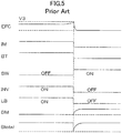
- the regenerative brake force (BT) operates until the overhead line voltage exceeds a control value, but when this control value is exceeded, operation of the inverter circuit (INV) stops, so the electric current (IM) of the alternating current rotating machine and the regenerative braking power (BT) are lost instantaneously.
- the electric train uses the regenerative brake with priority and has a structure such that when regenerative braking is insufficient for brake commands from the driver's console, this insufficiency is calculated and a mechanical brake force (BM) supplements the insufficient regenerative braking.
- BM mechanical brake force
- the mechanical brake obtains braking power through friction by causing a brake shoe to be pressed again a wheel or the like under air pressure, so that time is required until the mechanical brake operates sufficiently.
- the present invention provides a drive control device for an electric train that can improve the riding comfort and minimize changes in deceleration in an electric train, even in cases in which the regenerative load is insufficient during regenerative braking operation.
- a power controller controls an electric power converter so as to reduce a regenerative braking force through an alternating current rotating machine in a predetermined reduction pattern having a ramp reduction period longer than 0 when the voltage detected by the voltage detection unit exceeds a predetermined open-circuit voltage.
- FIG. 1 shows an example of the composition of a drive control device 1 for an electric train according to a first embodiment of the present invention.
- direct-current electric power from a non-represented transformer substation is input to the drive control device 1 by a collector 3 connecting to overhead lines 2.
- the direct-current electric power is input to an inverter circuit 5 that is a power converter, via a line breaker 4 that is a switch for opening or connecting this direct-current power.
- Return current from the drive control device 1 flows to a rail 7 via wheels 6, and returns to the negative side of the non-represented transformer substation.
- the drive control device 1 comprises an input filter that comprises a reactor 8 and a filter capacitor 9 and a capacitor voltage regulator 10 that is provided for protecting the inverter circuit 5 when the input voltage increases abnormally due to a lack of regenerative load during a regenerative braking action, and at the same time maintains the voltage at which the inverter circuit 5 operates even when the line breaker 4 is opened when the input voltage increases, and this capacitor voltage regulator 10 is composed of a switching device 11 connected to the rear part of the reactor 8 and a discharge resistor 12.
- inverter circuit 5 that is a power converter
- a voltage-type PWM inverter circuit is suitable, but this circuit composition is commonly known so that detailed explanation is omitted here.
- the inverter circuit 5 converts direct-current power to alternating-current power through a switching action, and drives an alternating current rotating machine 13 connected on the output side.
- the combination of the inverter circuit 5 and the alternating current rotating machine 13 can also be used as a regenerative brake that brakes the electric train, by the alternating current rotating machine 13 acting as a generator and kinetic energy being converted to electric energy and recovered.
- a power controller 14 is provided in the drive control device 1, into which at least a detected voltage EFC output from a voltage detector 15 that is impressed on the filter capacitor 9, and an electric current IM of the alternating current rotating machine 13 are input, and from which a control signal LON for the line breaker 4, a control signal OV for the switching device 11, a control signal GI for the switching device inside the inverter circuit 5, and a regenerative brake power signal indicating the regenerative force BT for a brake controller 16 are output.
- the voltage EFC impressed on the filter capacitor 9 is equivalent to the voltage between input terminals of the inverter circuit 5.
- the regenerative brake power signal BT indicates the output state of the alternating current rotating machine 13 in the period when a regenerative brake is operates. The method of generating the control signal OV for the switching device 11 and the control signal GI for the switching device inside the inverter circuit 5 is explained in detail below.
- the brake controller 16 calculates the insufficient brake force, using the brake force command signal BREF from the driver's console and the regenerative brake force signal from the power controller 14, and causes a mechanical braking force to act on the train wheels 6 through a mechanical brake.
- the mechanical brake operates using air pressure
- time is needed for the change in air pressure to be conveyed inside the air pipes for braking power to sufficiently increase. This time varies depending on the length of the air pipes and such factors, but is normally from 200 milliseconds to 2 seconds.
- FIG. 2 shows an example of the composition of the power controller 14 in a drive control device 1 for an electric train according to this embodiment.
- the composition relating to regulating the voltage EFC impressed on the filter capacitor 9 in this power controller 14, that is to say the voltage impressed between the input-side terminals of the inverter circuit 5, will be described.
- the detected voltage EFC detected by the voltage detector 15 is input to a voltage determiner 17 of the power controller 14.
- the voltage determiner 17 is composed of a first comparator 18 and a second comparator 19.
- a characteristic voltage will be defined for the drive control device 1 for an electric train according to this embodiment.
- the power controller 14 controls the switching device 11 of the capacitor voltage regulator 10 so that the detected voltage EFC is not less than a first voltage (V1) and not greater than a second voltage (V2).
- V1 it is possible to use the operating lower limit voltage on which the inverter circuit 5 that is a power converter operates, and as V2, it is possible to use the maximum used voltage of this inverter circuit 5.
- the operating lower limit voltage and the maximum used voltage are voltages predetermined by the inverter circuit 5 used, but as the inverter circuit 5 used in an electric railway in which the nominal voltage of the overhead lines 2 is DC 1500 V, it is possible to operate with a lower limit voltage of 900 V in a typical example and to operate with a maximum used voltage of 1900 V.
- V3 maintenance voltage
- V1 operating lower limit voltage of the inverter circuit 5
- V2 maximum used voltage
- V3 the third voltage V3 may also be used as an open-circuit voltage for opening the line breaker 4, but naturally this open-circuit voltage may be determined separately from the third voltage V3.
- the detected voltage EFC from the voltage detector 15 is input into the first comparator 18 and is compared with the third voltage V3. If EFC > V3, an output signal CM1 is set to a high level (first state). Simultaneously, the detected voltage EFC is input into the second comparator 19 and is compared with the second voltage V2. If EFC > V2, an output signal CM2 is set to a high level (second state).
- the signals CM1 and CM2 are input into a switching device control signal generator 20.
- the switching device control signal generator 20 generates an on/off control signal OV for intermittently controlling the switching device 11 of the capacitor voltage regulator 10, and is composed of a CH control device 21, an ON control device 22 and an OR circuit 23.
- the CMI1 signal from the first comparator 18 and a conduction ratio M are input into the CH control device 21 of the switching device control signal generator 20, and a CH signal is output.
- the CM2 signal from the second comparator 19 and an error signal ERR are input into the ON control device 22, and an ON signal is output.
- the CH signal from the CH control device 21 and the ON signal from the ON control device 22 are input into the OR circuit 23, and by finding the logical sum of the two signals an OV signal is output.
- the CH control device 21 generates a CH signal that is a switching signal (on/off signal) on condition of the CM1 signal being at a high level (first state).
- the CH signal is generated such that the ratio of on time accounted for in one period of PWM control is designated by the conduction ratio M (0 ⁇ M ⁇ 1).
- the conduction ratio M can be determined for example through the following formulas.
- M 0, if EFC ⁇ V3, and when EFC > V3, the settings may be such that the conduction ratio (M) becomes greater as the voltage deviation ( ⁇ V) increases.
- the error signal ERR input into the ON control device 22 is a signal generated by a non-represented protection circuit when the control power source voltage in the drive control device 1 falls below a designated value, or when a non-represented switching device composing the inverter circuit 5 is abnormal.
- the ON control device 22 generates an ON signal on condition of the CM2 signal or the ERR signal being at a high level.
- the ON signal is not a signal that repeats on/off with time, but is a signal that continues in an on state while the signal CM2 or the ERR signal is at a high level.
- the control condition of the switching device 11 has three states as shown below with respect to the detected voltage EFC.
- the CM1 signal output from the first comparator 18 is split and also used in switching a switch 24.
- a basic torque command PTR0 which is computed by an external control system on the basis of a command from a non-represented driver's console and is the necessary torque for the alternating current rotating machine 13, is input to one terminal of the switch 24, and 0 (zero) is input to the other terminal. This need not be zero, but may be a value sufficiently small compared to the basic torque command PTR0 from the driver's console.
- the torque of the regenerative brake through the alternating current rotating machine 13 is reduced in a predetermined reduction pattern as described below, and the input value (PTR0 or zero) of this switch 24 is the target value (target torque) after reduction by this reduction pattern.
- the switch is selected so that the output thereof becomes zero, and through this the torque of the regenerative brake is reduced in accordance with the predetermined reduction pattern to zero from the initial torque PTRO.
- the switch 24 is selected so that the output thereof becomes the basic torque command PTR0, and through this the torque of the regenerative brake is kept constant at the initial torque PTRO.
- the output of the switch 24 is input into a ramp processor 25.
- a ramp reduction time RMPL (> 0) that is the time for reducing the torque of the regenerative brake is input, and during this ramp reduction time RMPL, the torque is reduced from PTR0, which is the initial torque, to zero, which is the target torque.
- PTR0 which is the initial torque
- the torque may be reduced linearly from the initial torque to the target torque, or the torque may be reduced along a curve such as an exponential function.
- the data array of torque commands PTR(k) from moment to moment is input into the torque controller 26.
- the torque controller generates and outputs GI, which is a control signal for the switching device in the inverter circuit 5, so that the inverter circuit 5 outputs electric current and voltage such that the alternating current rotating machine 13 outputs a torque matching the torque commands PTR(k) on the basis of the torque commands PTR(k) and the electric current IM of the alternating current rotating machine 13.
- the torque controller 26 computes the torque the alternating current rotating machine 13 outputs on the basis of the electric current IM of the alternating current rotating machine 13, and outputs the regenerative brake power signal indicating the regenerative brake force BT.
- the torque commands PTR(k) are input into a comparator 27.
- the torque commands PTR(k) and a preset gate off level GOFL are compared, and when PTR(k) ⁇ GOFL (1 ⁇ k ⁇ n), an output signal TCT is output to an OR circuit 28 as a high level.
- the switch 29 is off and the control signal GI is off, so operation of the inverter circuit 5 stops.
- the gate off level GOFL is normally set as a value around 10 % less than the maximum value of the torque command PTR(k).
- the CM2 signal is also input into the OR circuit 28, so even when the CM2 signal is a high level, that is to say when the detected voltage EFC is greater than the second voltage V2, operation of the inverter circuit 5 stops due to the switch 29 being off and the control signal GI being off.
- the torque control condition of the alternating current rotating machine 13 caused by the inverter circuit 5 has three states as follows with respect to the detected voltage EFC.
- the control signal GI is output to the inverter circuit 5 with the torque command value at the initial torque PTRO.
- the control signal GI is output to the inverter circuit 5 until PTR(k) ⁇ GOFL.
- the control signal GI is turned off and the inverter circuit 5 stops.
- a line breaker introduction basic command LON1 generated by the top control system for connecting direct-current power in the line breaker 4 is input into a switch 30.
- the switch 30 is selected based on a signal, generated by an OR circuit 31, that is the logical sum of the CM1 signal and the CM2 signal, so that when the logical sum is a high level the switch 30 is turned off and the LON signal, which is a control signal for the line breaker 4, is turned off, that is to say the line breaker is opened.
- the operation of the drive control device 1 for an electric train composed as described above is explained next.
- the explanation will be for the case in which the electric train has a regenerative brake applied, that is to say when the drive control device I is regeneratively driving the alternating current rotating machine 13.
- the regenerative power from the alternating current rotating machine 13 flows from the drive control device 1 to the input side and regenerates regenerative power to the overhead lines 2.
- FIG. 3 shows an example of operation when the detected voltage is rising in the first embodiment of the present invention.
- the regenerative brake power (BT) also declines.
- the inverter circuit 5 (INV) is turned OFF and the conduction ratio M is 0, so the switching device 11 turns OFF and EFC is maintained at the third voltage V3.
- the regenerative brake power (BT) is gradually reduced in accordance with the predetermined reduction pattern such that the mechanical brake force (BM) can sufficiently follow, and phenomena such as the brake force (Btotal) of the electric train as a whole being insufficient or braking deceleration declining do not occur. Accordingly, there is no deterioration of riding comfort in the cars or lengthening of the braking distance due to fluctuations in deceleration.
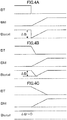
- FIG. 4 shows the total brake force (Btotal) of the electric train when the ramp reduction time RMPL of the regenerative brake force (BT) is changed with respect to the time the mechanical brake force (BM) is rising to the brake command from the driver's console, that is to say the state of fluctuation ( ⁇ B) in deceleration.
- RMPL is set to a time longer than the time for the mechanical brake to start up, it becomes possible to reliably compensate for the reduction in regenerative brake with the mechanical brake, so it is possible to substantially eliminate changes in deceleration (see FIG. 4C ).
- the response of the mechanical brake depends on the composition of the air route but is 200 milliseconds to around 2 seconds, so it is preferable to set the ramp reduction time RMPL to from 200 milliseconds to 2 seconds.
- the composition is such that the regenerative brake is restricted in a ramp form and is supplemented by the mechanical brake, but it is preferable to use an approach in which the ramp reduction time in this case (defined as the ramp reduction time during normal times) and the ramp reduction time (RMPL) in this embodiment can be set as separate values.
- the RMPL in this embodiment is set shorter than the normal lamp reduction time, so it is preferable to use an approach in which the normal lamp reduction time and the RMPL in this embodiment can be set as separate values.
- the RMPL When the RMPL is set from 200 milliseconds to 2 seconds as described above, the regenerative power amount is small and the capacity of the discharge resistor 12 does not become large compared to conventional devices.
- the conduction ratio (M) becomes greater as the voltage deviation ⁇ V (EFC - V3) increases, so that when the charge amount of the filter capacitor 9 becomes excessive, it is possible for the regenerative current to flow to the discharge resistor 12 side via the switching device 11. Accordingly, the detected voltage EFC never exceeds the second voltage V2, so voltage moderately exceeding V3 should be enough.
- the power controller 14 controls the inverter circuit 5 which is a power converter so that when the detected voltage EFC of the voltage detector 15 exceeds a predetermined open-circuit voltage V3, the regenerative brake force BT is reduced by the alternating current rotating machine 13 through a predetermined reduction pattern having a ramp reduction time RMPL longer than 0.
- the filter capacitor 9 connected to the two terminals on the input side of the inverter circuit 5 and the capacitor voltage regulator 10 connected between the two terminals in parallel with the filter capacitor 9 and having a switching device 11 are provided, and the power controller 14 regulates the charge amount on the filter capacitor 9 by intermittently controlling the switching device 11 so that the detected voltage EFC is not less than the first voltage V1 and not greater than the second voltage V2 over the ramp reduction time RMPL.
- the inverter circuit 5 is caused to operate even during the ramp reduction time RMPL during which the drive control device 1 is cut off from the overhead lines 2, and through this it is possible to convert the current of the alternating current rotating machine 13 to direct current via the inverter circuit 5 and consume such, making it possible to cause the regenerative brake to operate stably across this ramp reduction time RMPL.
- the parallel circuit of the filter capacitor 9 and the capacitor voltage regulator 10 is connected to the input unit of the inverter circuit 5, and thus an example was illustrated of a circuit composition in which the input voltage of the inverter circuit 5 can be controlled to not less than the first voltage V1 and not greater than second voltage V2, but by using the regenerative current output from the inverter circuit 5, if this is a circuit in which the input voltage of the inverter circuit 5 can be controlled to not less than V1 and not greater than V2, needless to say a similar effect can be achieved even with a different format using a storage battery and/or the like, for example.
- the drive control device 1 for an electric train when the voltage deviation ⁇ V, found by subtracting from the detected voltage EFC the third voltage V3 that is greater than the first voltage V1 and less than the second voltage V2, is 0 or negative, the power controller 14 makes the conduction ratio M of the switching device 11 to be 0, and when the voltage deviation ⁇ V is positive, executes control so that the conduction ratio M becomes greater as the voltage deviation becomes larger.
- the filter capacitor 9 can retain the charge accumulated to V3 without the electric charge stored in the filter capacitor 9 being discharged until the EFC is not greater than V3, and consequently it is possible to limit the electric current flowing to the discharge resistor 12 and it is possible to use a discharge resistor 12 with a small capacity.
- the power controller 14 controls the conduction ratio M to become 1 when the detected voltage EFC is not less than the second voltage V2, or controls the conduction ratio to become 1 when the control power source voltage in the drive control device 1 drops below a stipulated value or when the switching device comprising the inverter circuit 5 is abnormal, and consequently there are no fears that the switching device in the inverter circuit 5 will be destroyed, so it is possible to provide a highly reliable drive control device 1.
- a brake controller 16 is provided to control the mechanical brake force BM so as to supplement this lacking amount, and consequently it is possible to curtail insufficient brake force in the electric train as a whole and drops in braking deceleration.
- a characteristic of the power controller 14 is that the ramp reduction time RMPL is longer than the time needed for the mechanical brake force BM to increase as far as the brake command BREF, and consequently it is possible to supplement with certainty the amount by which regenerative braking has declined, using the mechanical brake, so it is possible to substantially eliminate changes in deceleration.
- the drive control device for an electric train uses a storage battery in place of the discharge resistor 12 in the capacitor voltage regulator 10.
- the composition and operation of devices other than this are the same as in the first embodiment, so description of such is omitted here.
- the drive control device for an electric train in addition to the effect achieved by the drive control device 1 of the first embodiment, when the regenerative load is lacking during operation of the regenerative brake, the storage battery is charged by the regenerative current, and this power that charges the storage battery can be used when the electric train is driven with strenuous effort, resulting in the effect that it is possible to increase the energy usage efficiency when operating the electric train.
- composition illustrated in the above embodiments shows one example of the content of the present invention, and it is possible to combine such with other commonly known art, to apply such to an electric train using a direct current rotating machine or to comprise such with variations such as omitting some parts without deviating from the scope of the present invention.
Landscapes
- Engineering & Computer Science (AREA)
- Power Engineering (AREA)
- Transportation (AREA)
- Mechanical Engineering (AREA)
- Physics & Mathematics (AREA)
- Electromagnetism (AREA)
- Life Sciences & Earth Sciences (AREA)
- Sustainable Development (AREA)
- Sustainable Energy (AREA)
- Electric Propulsion And Braking For Vehicles (AREA)
Claims (12)
- Dispositif de commande d'entraînement pour un train électrique, comprenant:- un commutateur (4) qui est adapté pour connecter ou pour ouvrir une puissance électrique en courant continu;- un convertisseur de puissance (5) dans lequel la puissance électrique en courant continu est injectée via le commutateur (4) entre deux bornes sur un côté d'entrée, qui est adapté pour convertir la puissance électrique en courant continu en une puissance électrique en courant alternatif via une opération de commutation, et pour entraîner une machine rotative à courant alternatif (13) connectée sur un côté de sortie;- un détecteur de tension (15) qui est adapté à détecter une tension (EFC) entre les deux bornes;- un condensateur de filtrage (9) connecté entre les deux bornes; et- un régulateur de tension de condensateur (10) connecté entre les deux bornes en parallèle au condensateur de filtrage (9) et ayant un dispositif de commutation (11); caractérisé en ce qu'il comprend- un contrôleur de puissance (14) qui est adapté à commander le convertisseur de puissance (5) de telle façon que quand la tension (EFC) détectée par le détecteur de tension (15) excède une tension en circuit ouvert prédéterminée (V3), le commutateur (4) s'ouvre et une puissance de freinage à régénération est réduite par la machine rotative à courant alternatif (13) dans un motif de réduction prédéterminé ayant un temps de réduction en rampe (RMPL) plus long que zéro ; dans lequel le contrôleur de puissance (14) est adapté pour commander de façon intermittente le dispositif de commutation (11) et réguler une charge quantitative dans le condensateur de filtrage (9) de telle façon que la tension détectée (EFC) n'est pas inférieure à une première tension (V1) et n'est pas supérieure à une seconde tension (V2) sur le temps de réduction en rampe (RMPL),
dans lequel le contrôleur de puissance (14) est adapté à fixer un rapport de conduction du dispositif de commutation (11) à zéro quand une déviation de tension est zéro ou négative, et quand la déviation de tension est positive, à augmenter le rapport de conduction quand la déviation de tension augmente, dans lequel la déviation de tension est déterminée en soustrayant une troisième tension (V3) depuis la tension détectée (EFC), dans lequel la troisième tension (V3) est supérieure à la première tension (V1) et est inférieure à la seconde tension (V2), et la tension en circuit ouvert prédéterminée est la troisième tension (V3). - Dispositif de commande d'entraînement selon la revendication 1,
dans lequel le contrôleur de puissance (14) est tel que la première tension est une tension limite inférieure de fonctionnement du convertisseur de puissance (5), et la seconde tension est une tension utilisée maximum du convertisseur de puissance (5). - Dispositif de commande d'entraînement pour un train électrique selon la revendication 1,
dans lequel le contrôleur de puissance (14) est adapté pour fixer le rapport de conduction à la valeur un quand la tension détectée est égale ou supérieure à la seconde tension. - Dispositif de commande d'entraînement pour un train électrique selon la revendication 1, dans lequel le contrôleur de puissance (14) est adapté à fixer le rapport de conduction à la valeur un quand une tension d'une source de puissance de commande dans le dispositif de commande d'entraînement (11) chute au-dessous d'une valeur prescrite, ou quand un dispositif de commutation comprenant le convertisseur de puissance (5) est déterminé comme étant anormal.
- Dispositif de commande d'entraînement selon l'une quelconque des revendications 1 à 4,
dans lequel le contrôleur de puissance (14) comprend :- un moyen de détermination de tension (17) ayant un premier comparateur (18) pour générer un signal CM1 qui est un premier état quand la tension détectée est égale ou supérieure à la troisième tension, et un second comparateur (19) pour générer un signal CM2 qui est un second état quand la tension détectée est égale ou supérieure à la seconde tension ; et- un générateur de signal de commande de dispositif de commutation (20) ayant un dispositif de commande CH (21) pour générer un signal CH qui est un signal intermittent qui s'ouvre en accord avec le rapport de conduction quand le signal CM1 est dans le premier état, un dispositif de commande ON (22) pour générer un signal ON quand le signal CM2 est dans le second état, et un circuit OR (23) pour générer un signal de somme logique du signal CH et du signal ON ;
dans lequel le contrôleur de puissance (14) est adapté pour commander le dispositif de commutation (11) via le signal de somme logique. - Dispositif de commande d'entraînement selon l'une quelconque des revendications 1 à 5,
dans lequel le contrôleur de puissance (14) est configuré pour :- commander le convertisseur de puissance (5) de façon qu'un couple délivré par la machine rotative à courant alternatif (13) maintient un couple initial ordonné depuis une console du conducteur quand la tension détectée est égale ou inférieure à la troisième tension ;- commander le convertisseur de puissance (5) de façon que le couple délivré par la machine rotative à courant alternatif (13) est réduit depuis le couple initial en accord avec un motif de réduction prédéterminé quand la tension détectée est supérieure à la troisième tension et inférieure à la seconde tension ; et- arrêter le convertisseur de puissance (5) quand la tension détectée est égale ou supérieure à la seconde tension. - Dispositif de commande d'entraînement selon l'une quelconque des revendications 1 à 6,
dans lequel le contrôleur de puissance (14) comprend :- un commutateur (24) avec lequel la sélection d'un couple cible est accomplie en accord avec la tension détectée ;- un processeur en rampe (25) dans lequel est injecté le temps de réduction en rampe (RMPL) et qui est adapté à générer un ordre de couple pour réduire depuis le couple initial vers le couple cible en accord avec le motif de réduction prédéterminée ; et- un contrôleur de couple (26) dans lequel est injecté un courant électrique IM de la machine rotative à courant alternatif (13) et qui est adapté à générer un signal de commande (GI) pour le convertisseur de puissance (5) de telle façon que la machine rotative à courant alternatif (13) délivre un couple en accord avec l'ordre de couple, sur la base de ce courant électrique IM ;
dans lequel le contrôleur de puissance (14) est adapté à commander le convertisseur de puissance (5) via le signal de commande (GI). - Dispositif de commande d'entraînement selon l'une quelconque des revendications 1 à 7,
dans lequel le régulateur de tension de condensateur (10) a une structure en série du dispositif de commutation (11) et d'une résistance de décharge (12). - Dispositif de commande d'entraînement selon l'une quelconque des revendications 1 à 7,
dans lequel le régulateur de tension de condensateur (10) a une structure en série du dispositif de commutation et d'une batterie de stockage. - Dispositif de commande d'entraînement selon l'une quelconque des revendications 1 à 9,
comprenant en outre un dispositif de commande de freinage (16) de sorte que, quand un signal de force de freinage en régénération indiquant l'état de sortie de la machine rotative à courant alternatif (13) et un ordre de force de freinage sont injectés et que le signal de force de freinage en régénération est en défaut par rapport à l'ordre de force de freinage, le dispositif de commande de freinage (16) est adapté à commander une force de freinage mécanique pour suppléer à cette quantité en défaut. - Dispositif de commande d'entraînement selon la revendication 10,
dans lequel le contrôleur de puissance (14) est tel que le temps de réduction en rampe (RMPL) injecté est plus long que le temps nécessaire pour que la force de freinage mécanique augmente à la valeur de l'ordre de freinage. - Dispositif de commande d'entraînement selon la revendication 11,
dans lequel le contrôleur de puissance (14) est tel que le temps de réduction en rampe (RMPL) injecté n'est pas inférieur à 200 ms et n'est pas supérieur à 2 secondes.
Applications Claiming Priority (1)
| Application Number | Priority Date | Filing Date | Title |
|---|---|---|---|
| PCT/JP2009/007005 WO2011074045A1 (fr) | 2009-12-18 | 2009-12-18 | Appareil de commande d'entraînement de véhicule électrique |
Publications (3)
| Publication Number | Publication Date |
|---|---|
| EP2514626A1 EP2514626A1 (fr) | 2012-10-24 |
| EP2514626A4 EP2514626A4 (fr) | 2014-10-22 |
| EP2514626B1 true EP2514626B1 (fr) | 2019-04-24 |
Family
ID=43048768
Family Applications (1)
| Application Number | Title | Priority Date | Filing Date |
|---|---|---|---|
| EP09852242.8A Active EP2514626B1 (fr) | 2009-12-18 | 2009-12-18 | Appareil de commande d'entraînement de véhicule électrique |
Country Status (8)
| Country | Link |
|---|---|
| US (1) | US8710774B2 (fr) |
| EP (1) | EP2514626B1 (fr) |
| JP (1) | JP4561938B1 (fr) |
| KR (1) | KR20120069762A (fr) |
| CN (1) | CN102791514B (fr) |
| BR (1) | BR112012014205A2 (fr) |
| CA (1) | CA2779870C (fr) |
| WO (1) | WO2011074045A1 (fr) |
Families Citing this family (16)
| Publication number | Priority date | Publication date | Assignee | Title |
|---|---|---|---|---|
| JP5523639B2 (ja) * | 2012-01-12 | 2014-06-18 | 三菱電機株式会社 | 電気車制御装置 |
| US9735715B2 (en) * | 2013-03-15 | 2017-08-15 | Regal Beloit America, Inc. | Methods and systems for inductive energy management |
| JP6182021B2 (ja) * | 2013-08-28 | 2017-08-16 | 株式会社日立製作所 | 電力変換装置 |
| RU2561068C1 (ru) * | 2014-05-13 | 2015-08-20 | Федеральное государственное бюджетное образовательное учреждение высшего профессионального образования "Дальневосточный государственный университет путей сообщения" (ДВГУПС) | Способ управления зависимым инвертором однофазного переменного тока |
| JP6335040B2 (ja) * | 2014-06-20 | 2018-05-30 | 株式会社東芝 | 車両用制御装置 |
| DE102014214741B4 (de) * | 2014-07-28 | 2026-03-05 | Robert Bosch Gmbh | Verfahren und Vorrichtung zum Betreiben einer Parkbremse eines Kraftfahrzeugs |
| KR101645714B1 (ko) | 2015-08-11 | 2016-08-04 | (주)세원물산 | 전기자동차 구동부용 마운팅 장치 |
| JP6336953B2 (ja) * | 2015-10-08 | 2018-06-06 | 本田技研工業株式会社 | 駆動装置、輸送機器及び制御方法 |
| CN105235536B (zh) * | 2015-11-04 | 2017-11-28 | 株洲中车时代电气股份有限公司 | 一种动车组牵引系统及能量控制方法 |
| US9950620B1 (en) * | 2017-01-18 | 2018-04-24 | GM Global Technology Operations LLC | Regenerative and friction power indicator for a vehicle braking system |
| RU2689786C1 (ru) * | 2018-06-13 | 2019-05-29 | Общество с ограниченной ответственностью "Транспортные прогрессивные технологии" | Способ управления многозонным выпрямительно-инверторным преобразователем однофазного переменного тока |
| JP6937913B2 (ja) * | 2018-07-04 | 2021-09-22 | 三菱電機株式会社 | 鉄道車両用制御装置 |
| CN111463768A (zh) * | 2019-01-21 | 2020-07-28 | 广东美的制冷设备有限公司 | 供电保护电路板及空调器 |
| DE102019214870A1 (de) * | 2019-06-17 | 2020-12-17 | Volkswagen Aktiengesellschaft | Schaltungsanordnung für ein Kraftfahrzeug und Verfahren zum Stabilisieren einer Gleichspannung eines Hochvolt-Gleichspannungszwischenkreises in einem Kraftfahrzeug |
| CN110861503A (zh) * | 2019-11-27 | 2020-03-06 | 南京巨基汽车电子有限公司 | 一种智能新能源汽车能量回馈制动系统以及控制方法 |
| US11753028B1 (en) * | 2022-08-31 | 2023-09-12 | Nissan North America, Inc. | Pedal control system and method for an electric vehicle |
Family Cites Families (17)
| Publication number | Priority date | Publication date | Assignee | Title |
|---|---|---|---|---|
| JPS58154304A (ja) * | 1982-03-05 | 1983-09-13 | Mitsubishi Electric Corp | 電気車の制動制御装置 |
| JPS60109701A (ja) * | 1983-11-16 | 1985-06-15 | Hitachi Ltd | 電気車用制動制御装置 |
| JPH0799883B2 (ja) * | 1988-11-29 | 1995-10-25 | 三菱電機株式会社 | 電気車用ブレーキ装置 |
| JP2680186B2 (ja) * | 1990-11-28 | 1997-11-19 | 株式会社日立製作所 | 電気車制御装置 |
| JPH0690503A (ja) * | 1992-09-07 | 1994-03-29 | Mitsubishi Electric Corp | 電気車の制動装置 |
| JP3089958B2 (ja) * | 1994-12-06 | 2000-09-18 | 三菱自動車工業株式会社 | 電気自動車の制動制御装置 |
| JP3943928B2 (ja) | 2001-12-25 | 2007-07-11 | 株式会社東芝 | 電力変換装置 |
| JP3747858B2 (ja) * | 2002-02-01 | 2006-02-22 | 株式会社日立製作所 | 車両用インバータの制御方法およびインバータ制御器 |
| US7201244B2 (en) * | 2003-10-03 | 2007-04-10 | Letourneau, Inc. | Vehicle for materials handling and other industrial uses |
| JP5000893B2 (ja) * | 2005-01-27 | 2012-08-15 | 日立オートモティブシステムズ株式会社 | 電動ブレーキ制御装置及び電動ブレーキ制御方法 |
| US7132757B2 (en) * | 2005-02-17 | 2006-11-07 | General Electric Company | Power control system and method |
| WO2006126272A1 (fr) * | 2005-05-26 | 2006-11-30 | Mitsubishi Denki Kabushiki Kaisha | Module de commande de moteur a courant alternatif a vitesse variable |
| WO2007013141A1 (fr) * | 2005-07-26 | 2007-02-01 | Mitsubishi Denki Kabushiki Kaisha | Dispositif de commande d’un élévateur-transporteur |
| CA2587668C (fr) * | 2005-09-15 | 2013-07-30 | Mitsubishi Electric Corporation | Dispositif et methode de commande de freinage pour vehicule electrique |
| WO2008053554A1 (fr) * | 2006-11-02 | 2008-05-08 | Mitsubishi Electric Corporation | Appareil de commande de voiture à moteur électrique |
| KR20080044097A (ko) * | 2006-11-15 | 2008-05-20 | 현대자동차주식회사 | 수퍼커패시터를 이용한 연료전지 차량의 회생제동 시스템 |
| JP2009189198A (ja) | 2008-02-08 | 2009-08-20 | Toyo Electric Mfg Co Ltd | 電気車制御装置 |
-
2009
- 2009-12-18 EP EP09852242.8A patent/EP2514626B1/fr active Active
- 2009-12-18 US US13/508,692 patent/US8710774B2/en active Active
- 2009-12-18 CA CA2779870A patent/CA2779870C/fr not_active Expired - Fee Related
- 2009-12-18 BR BR112012014205A patent/BR112012014205A2/pt not_active Application Discontinuation
- 2009-12-18 JP JP2010520378A patent/JP4561938B1/ja active Active
- 2009-12-18 CN CN200980163033.5A patent/CN102791514B/zh active Active
- 2009-12-18 KR KR1020127012404A patent/KR20120069762A/ko not_active Ceased
- 2009-12-18 WO PCT/JP2009/007005 patent/WO2011074045A1/fr not_active Ceased
Non-Patent Citations (1)
| Title |
|---|
| None * |
Also Published As
| Publication number | Publication date |
|---|---|
| JPWO2011074045A1 (ja) | 2013-04-25 |
| EP2514626A1 (fr) | 2012-10-24 |
| US20120227616A1 (en) | 2012-09-13 |
| US8710774B2 (en) | 2014-04-29 |
| KR20120069762A (ko) | 2012-06-28 |
| WO2011074045A1 (fr) | 2011-06-23 |
| CN102791514A (zh) | 2012-11-21 |
| CA2779870A1 (fr) | 2011-06-23 |
| CN102791514B (zh) | 2016-03-23 |
| JP4561938B1 (ja) | 2010-10-13 |
| EP2514626A4 (fr) | 2014-10-22 |
| CA2779870C (fr) | 2014-10-21 |
| BR112012014205A2 (pt) | 2016-06-14 |
Similar Documents
| Publication | Publication Date | Title |
|---|---|---|
| US8710774B2 (en) | Electric train drive control device | |
| CA2740979C (fr) | Dispositif de commande de propulsion pour voiture electrique | |
| KR101419203B1 (ko) | 전기차 추진용 전력 변환 장치 | |
| EP2647521B1 (fr) | Dispositif de commande pour véhicule électrique | |
| KR101627960B1 (ko) | 전기차 제어장치 | |
| JP6055258B2 (ja) | 鉄道車両 | |
| US9013125B2 (en) | Electric power converter of electric rolling stock | |
| JP2006014489A (ja) | 電気車の電力変換装置 | |
| EP3694094A1 (fr) | Commande de conversion de puissance | |
| JP2008154355A (ja) | 蓄電設備 | |
| JP2002369304A (ja) | 電気車の制御装置 | |
| JP2004168214A (ja) | 饋電電圧補償装置 | |
| JP4670827B2 (ja) | 車両制御システム | |
| JP2001320831A (ja) | 電鉄用電気車 | |
| KR20070018302A (ko) | 보조 배터리를 이용한 차량용 충전 시스템 및 그 제어 방법 | |
| JP2008074180A (ja) | 電力貯蔵システム | |
| CN104842806B (zh) | 铁路车辆用驱动装置 | |
| KR102512649B1 (ko) | 소비전력 개선을 위한 전동차용 회생전력 저장시스템 | |
| JP2006044887A (ja) | エレベータ制御システム |
Legal Events
| Date | Code | Title | Description |
|---|---|---|---|
| PUAI | Public reference made under article 153(3) epc to a published international application that has entered the european phase |
Free format text: ORIGINAL CODE: 0009012 |
|
| 17P | Request for examination filed |
Effective date: 20120604 |
|
| AK | Designated contracting states |
Kind code of ref document: A1 Designated state(s): AT BE BG CH CY CZ DE DK EE ES FI FR GB GR HR HU IE IS IT LI LT LU LV MC MK MT NL NO PL PT RO SE SI SK SM TR |
|
| DAX | Request for extension of the european patent (deleted) | ||
| A4 | Supplementary search report drawn up and despatched |
Effective date: 20140923 |
|
| RIC1 | Information provided on ipc code assigned before grant |
Ipc: B60L 7/14 20060101AFI20140917BHEP Ipc: B60L 3/00 20060101ALI20140917BHEP Ipc: B60L 7/24 20060101ALI20140917BHEP |
|
| 17Q | First examination report despatched |
Effective date: 20160127 |
|
| STAA | Information on the status of an ep patent application or granted ep patent |
Free format text: STATUS: EXAMINATION IS IN PROGRESS |
|
| GRAP | Despatch of communication of intention to grant a patent |
Free format text: ORIGINAL CODE: EPIDOSNIGR1 |
|
| STAA | Information on the status of an ep patent application or granted ep patent |
Free format text: STATUS: GRANT OF PATENT IS INTENDED |
|
| INTG | Intention to grant announced |
Effective date: 20181105 |
|
| GRAS | Grant fee paid |
Free format text: ORIGINAL CODE: EPIDOSNIGR3 |
|
| GRAA | (expected) grant |
Free format text: ORIGINAL CODE: 0009210 |
|
| STAA | Information on the status of an ep patent application or granted ep patent |
Free format text: STATUS: THE PATENT HAS BEEN GRANTED |
|
| AK | Designated contracting states |
Kind code of ref document: B1 Designated state(s): AT BE BG CH CY CZ DE DK EE ES FI FR GB GR HR HU IE IS IT LI LT LU LV MC MK MT NL NO PL PT RO SE SI SK SM TR |
|
| REG | Reference to a national code |
Ref country code: GB Ref legal event code: FG4D |
|
| REG | Reference to a national code |
Ref country code: CH Ref legal event code: EP |
|
| REG | Reference to a national code |
Ref country code: AT Ref legal event code: REF Ref document number: 1123729 Country of ref document: AT Kind code of ref document: T Effective date: 20190515 Ref country code: IE Ref legal event code: FG4D |
|
| REG | Reference to a national code |
Ref country code: DE Ref legal event code: R096 Ref document number: 602009058072 Country of ref document: DE |
|
| REG | Reference to a national code |
Ref country code: NL Ref legal event code: MP Effective date: 20190424 |
|
| REG | Reference to a national code |
Ref country code: LT Ref legal event code: MG4D |
|
| PG25 | Lapsed in a contracting state [announced via postgrant information from national office to epo] |
Ref country code: NL Free format text: LAPSE BECAUSE OF FAILURE TO SUBMIT A TRANSLATION OF THE DESCRIPTION OR TO PAY THE FEE WITHIN THE PRESCRIBED TIME-LIMIT Effective date: 20190424 |
|
| PG25 | Lapsed in a contracting state [announced via postgrant information from national office to epo] |
Ref country code: PT Free format text: LAPSE BECAUSE OF FAILURE TO SUBMIT A TRANSLATION OF THE DESCRIPTION OR TO PAY THE FEE WITHIN THE PRESCRIBED TIME-LIMIT Effective date: 20190824 Ref country code: ES Free format text: LAPSE BECAUSE OF FAILURE TO SUBMIT A TRANSLATION OF THE DESCRIPTION OR TO PAY THE FEE WITHIN THE PRESCRIBED TIME-LIMIT Effective date: 20190424 Ref country code: LT Free format text: LAPSE BECAUSE OF FAILURE TO SUBMIT A TRANSLATION OF THE DESCRIPTION OR TO PAY THE FEE WITHIN THE PRESCRIBED TIME-LIMIT Effective date: 20190424 Ref country code: NO Free format text: LAPSE BECAUSE OF FAILURE TO SUBMIT A TRANSLATION OF THE DESCRIPTION OR TO PAY THE FEE WITHIN THE PRESCRIBED TIME-LIMIT Effective date: 20190724 Ref country code: FI Free format text: LAPSE BECAUSE OF FAILURE TO SUBMIT A TRANSLATION OF THE DESCRIPTION OR TO PAY THE FEE WITHIN THE PRESCRIBED TIME-LIMIT Effective date: 20190424 Ref country code: HR Free format text: LAPSE BECAUSE OF FAILURE TO SUBMIT A TRANSLATION OF THE DESCRIPTION OR TO PAY THE FEE WITHIN THE PRESCRIBED TIME-LIMIT Effective date: 20190424 Ref country code: SE Free format text: LAPSE BECAUSE OF FAILURE TO SUBMIT A TRANSLATION OF THE DESCRIPTION OR TO PAY THE FEE WITHIN THE PRESCRIBED TIME-LIMIT Effective date: 20190424 |
|
| PG25 | Lapsed in a contracting state [announced via postgrant information from national office to epo] |
Ref country code: PL Free format text: LAPSE BECAUSE OF FAILURE TO SUBMIT A TRANSLATION OF THE DESCRIPTION OR TO PAY THE FEE WITHIN THE PRESCRIBED TIME-LIMIT Effective date: 20190424 Ref country code: GR Free format text: LAPSE BECAUSE OF FAILURE TO SUBMIT A TRANSLATION OF THE DESCRIPTION OR TO PAY THE FEE WITHIN THE PRESCRIBED TIME-LIMIT Effective date: 20190725 Ref country code: LV Free format text: LAPSE BECAUSE OF FAILURE TO SUBMIT A TRANSLATION OF THE DESCRIPTION OR TO PAY THE FEE WITHIN THE PRESCRIBED TIME-LIMIT Effective date: 20190424 Ref country code: BG Free format text: LAPSE BECAUSE OF FAILURE TO SUBMIT A TRANSLATION OF THE DESCRIPTION OR TO PAY THE FEE WITHIN THE PRESCRIBED TIME-LIMIT Effective date: 20190724 |
|
| REG | Reference to a national code |
Ref country code: AT Ref legal event code: MK05 Ref document number: 1123729 Country of ref document: AT Kind code of ref document: T Effective date: 20190424 |
|
| PG25 | Lapsed in a contracting state [announced via postgrant information from national office to epo] |
Ref country code: IS Free format text: LAPSE BECAUSE OF FAILURE TO SUBMIT A TRANSLATION OF THE DESCRIPTION OR TO PAY THE FEE WITHIN THE PRESCRIBED TIME-LIMIT Effective date: 20190824 |
|
| REG | Reference to a national code |
Ref country code: DE Ref legal event code: R097 Ref document number: 602009058072 Country of ref document: DE |
|
| PG25 | Lapsed in a contracting state [announced via postgrant information from national office to epo] |
Ref country code: AT Free format text: LAPSE BECAUSE OF FAILURE TO SUBMIT A TRANSLATION OF THE DESCRIPTION OR TO PAY THE FEE WITHIN THE PRESCRIBED TIME-LIMIT Effective date: 20190424 Ref country code: CZ Free format text: LAPSE BECAUSE OF FAILURE TO SUBMIT A TRANSLATION OF THE DESCRIPTION OR TO PAY THE FEE WITHIN THE PRESCRIBED TIME-LIMIT Effective date: 20190424 Ref country code: RO Free format text: LAPSE BECAUSE OF FAILURE TO SUBMIT A TRANSLATION OF THE DESCRIPTION OR TO PAY THE FEE WITHIN THE PRESCRIBED TIME-LIMIT Effective date: 20190424 Ref country code: SK Free format text: LAPSE BECAUSE OF FAILURE TO SUBMIT A TRANSLATION OF THE DESCRIPTION OR TO PAY THE FEE WITHIN THE PRESCRIBED TIME-LIMIT Effective date: 20190424 Ref country code: EE Free format text: LAPSE BECAUSE OF FAILURE TO SUBMIT A TRANSLATION OF THE DESCRIPTION OR TO PAY THE FEE WITHIN THE PRESCRIBED TIME-LIMIT Effective date: 20190424 Ref country code: DK Free format text: LAPSE BECAUSE OF FAILURE TO SUBMIT A TRANSLATION OF THE DESCRIPTION OR TO PAY THE FEE WITHIN THE PRESCRIBED TIME-LIMIT Effective date: 20190424 |
|
| PG25 | Lapsed in a contracting state [announced via postgrant information from national office to epo] |
Ref country code: SM Free format text: LAPSE BECAUSE OF FAILURE TO SUBMIT A TRANSLATION OF THE DESCRIPTION OR TO PAY THE FEE WITHIN THE PRESCRIBED TIME-LIMIT Effective date: 20190424 Ref country code: IT Free format text: LAPSE BECAUSE OF FAILURE TO SUBMIT A TRANSLATION OF THE DESCRIPTION OR TO PAY THE FEE WITHIN THE PRESCRIBED TIME-LIMIT Effective date: 20190424 |
|
| PLBE | No opposition filed within time limit |
Free format text: ORIGINAL CODE: 0009261 |
|
| STAA | Information on the status of an ep patent application or granted ep patent |
Free format text: STATUS: NO OPPOSITION FILED WITHIN TIME LIMIT |
|
| PG25 | Lapsed in a contracting state [announced via postgrant information from national office to epo] |
Ref country code: TR Free format text: LAPSE BECAUSE OF FAILURE TO SUBMIT A TRANSLATION OF THE DESCRIPTION OR TO PAY THE FEE WITHIN THE PRESCRIBED TIME-LIMIT Effective date: 20190424 |
|
| 26N | No opposition filed |
Effective date: 20200127 |
|
| PG25 | Lapsed in a contracting state [announced via postgrant information from national office to epo] |
Ref country code: SI Free format text: LAPSE BECAUSE OF FAILURE TO SUBMIT A TRANSLATION OF THE DESCRIPTION OR TO PAY THE FEE WITHIN THE PRESCRIBED TIME-LIMIT Effective date: 20190424 |
|
| REG | Reference to a national code |
Ref country code: CH Ref legal event code: PL |
|
| REG | Reference to a national code |
Ref country code: BE Ref legal event code: MM Effective date: 20191231 |
|
| PG25 | Lapsed in a contracting state [announced via postgrant information from national office to epo] |
Ref country code: MC Free format text: LAPSE BECAUSE OF FAILURE TO SUBMIT A TRANSLATION OF THE DESCRIPTION OR TO PAY THE FEE WITHIN THE PRESCRIBED TIME-LIMIT Effective date: 20190424 |
|
| GBPC | Gb: european patent ceased through non-payment of renewal fee |
Effective date: 20191218 |
|
| PG25 | Lapsed in a contracting state [announced via postgrant information from national office to epo] |
Ref country code: LU Free format text: LAPSE BECAUSE OF NON-PAYMENT OF DUE FEES Effective date: 20191218 Ref country code: GB Free format text: LAPSE BECAUSE OF NON-PAYMENT OF DUE FEES Effective date: 20191218 Ref country code: FR Free format text: LAPSE BECAUSE OF NON-PAYMENT OF DUE FEES Effective date: 20191231 Ref country code: IE Free format text: LAPSE BECAUSE OF NON-PAYMENT OF DUE FEES Effective date: 20191218 |
|
| PG25 | Lapsed in a contracting state [announced via postgrant information from national office to epo] |
Ref country code: LI Free format text: LAPSE BECAUSE OF NON-PAYMENT OF DUE FEES Effective date: 20191231 Ref country code: BE Free format text: LAPSE BECAUSE OF NON-PAYMENT OF DUE FEES Effective date: 20191231 Ref country code: CH Free format text: LAPSE BECAUSE OF NON-PAYMENT OF DUE FEES Effective date: 20191231 |
|
| PG25 | Lapsed in a contracting state [announced via postgrant information from national office to epo] |
Ref country code: CY Free format text: LAPSE BECAUSE OF FAILURE TO SUBMIT A TRANSLATION OF THE DESCRIPTION OR TO PAY THE FEE WITHIN THE PRESCRIBED TIME-LIMIT Effective date: 20190424 |
|
| PG25 | Lapsed in a contracting state [announced via postgrant information from national office to epo] |
Ref country code: HU Free format text: LAPSE BECAUSE OF FAILURE TO SUBMIT A TRANSLATION OF THE DESCRIPTION OR TO PAY THE FEE WITHIN THE PRESCRIBED TIME-LIMIT; INVALID AB INITIO Effective date: 20091218 Ref country code: MT Free format text: LAPSE BECAUSE OF FAILURE TO SUBMIT A TRANSLATION OF THE DESCRIPTION OR TO PAY THE FEE WITHIN THE PRESCRIBED TIME-LIMIT Effective date: 20190424 |
|
| REG | Reference to a national code |
Ref country code: DE Ref legal event code: R084 Ref document number: 602009058072 Country of ref document: DE |
|
| PG25 | Lapsed in a contracting state [announced via postgrant information from national office to epo] |
Ref country code: MK Free format text: LAPSE BECAUSE OF FAILURE TO SUBMIT A TRANSLATION OF THE DESCRIPTION OR TO PAY THE FEE WITHIN THE PRESCRIBED TIME-LIMIT Effective date: 20190424 |
|
| P01 | Opt-out of the competence of the unified patent court (upc) registered |
Effective date: 20230512 |
|
| PGFP | Annual fee paid to national office [announced via postgrant information from national office to epo] |
Ref country code: DE Payment date: 20251028 Year of fee payment: 17 |