EP2514980A2 - Einsatz für thermoplastische Halterung, und Zusammenbauverfahren des Einsatzes mit der Halterung - Google Patents
Einsatz für thermoplastische Halterung, und Zusammenbauverfahren des Einsatzes mit der Halterung Download PDFInfo
- Publication number
- EP2514980A2 EP2514980A2 EP12354024A EP12354024A EP2514980A2 EP 2514980 A2 EP2514980 A2 EP 2514980A2 EP 12354024 A EP12354024 A EP 12354024A EP 12354024 A EP12354024 A EP 12354024A EP 2514980 A2 EP2514980 A2 EP 2514980A2
- Authority
- EP
- European Patent Office
- Prior art keywords
- insert
- head
- support
- barrel
- opposite
- Prior art date
- Legal status (The legal status is an assumption and is not a legal conclusion. Google has not performed a legal analysis and makes no representation as to the accuracy of the status listed.)
- Granted
Links
- 229920001169 thermoplastic Polymers 0.000 title claims abstract description 27
- 239000004416 thermosoftening plastic Substances 0.000 title claims abstract description 27
- 238000000034 method Methods 0.000 title claims abstract description 9
- 125000006850 spacer group Chemical group 0.000 claims abstract description 23
- 239000012815 thermoplastic material Substances 0.000 claims description 20
- 238000010438 heat treatment Methods 0.000 claims description 8
- 238000002844 melting Methods 0.000 claims description 5
- 230000008018 melting Effects 0.000 claims description 5
- 238000001816 cooling Methods 0.000 description 3
- 238000005242 forging Methods 0.000 description 2
- 238000003780 insertion Methods 0.000 description 2
- 230000037431 insertion Effects 0.000 description 2
- 238000000926 separation method Methods 0.000 description 2
- 238000010273 cold forging Methods 0.000 description 1
- 238000006073 displacement reaction Methods 0.000 description 1
- 238000005485 electric heating Methods 0.000 description 1
- 230000005294 ferromagnetic effect Effects 0.000 description 1
- 230000004927 fusion Effects 0.000 description 1
- 230000006698 induction Effects 0.000 description 1
- 238000003754 machining Methods 0.000 description 1
- 239000012768 molten material Substances 0.000 description 1
- 238000000465 moulding Methods 0.000 description 1
- 230000001737 promoting effect Effects 0.000 description 1
- 239000002699 waste material Substances 0.000 description 1
Images


Classifications
-
- F—MECHANICAL ENGINEERING; LIGHTING; HEATING; WEAPONS; BLASTING
- F16—ENGINEERING ELEMENTS AND UNITS; GENERAL MEASURES FOR PRODUCING AND MAINTAINING EFFECTIVE FUNCTIONING OF MACHINES OR INSTALLATIONS; THERMAL INSULATION IN GENERAL
- F16B—DEVICES FOR FASTENING OR SECURING CONSTRUCTIONAL ELEMENTS OR MACHINE PARTS TOGETHER, e.g. NAILS, BOLTS, CIRCLIPS, CLAMPS, CLIPS OR WEDGES; JOINTS OR JOINTING
- F16B37/00—Nuts or like thread-engaging members
- F16B37/12—Nuts or like thread-engaging members with thread-engaging surfaces formed by inserted coil-springs, discs, or the like; Independent pieces of wound wire used as nuts; Threaded inserts for holes
- F16B37/122—Threaded inserts, e.g. "rampa bolts"
-
- B—PERFORMING OPERATIONS; TRANSPORTING
- B29—WORKING OF PLASTICS; WORKING OF SUBSTANCES IN A PLASTIC STATE IN GENERAL
- B29C—SHAPING OR JOINING OF PLASTICS; SHAPING OF MATERIAL IN A PLASTIC STATE, NOT OTHERWISE PROVIDED FOR; AFTER-TREATMENT OF THE SHAPED PRODUCTS, e.g. REPAIRING
- B29C65/00—Joining or sealing of preformed parts, e.g. welding of plastics materials; Apparatus therefor
- B29C65/56—Joining or sealing of preformed parts, e.g. welding of plastics materials; Apparatus therefor using mechanical means or mechanical connections, e.g. form-fits
-
- B—PERFORMING OPERATIONS; TRANSPORTING
- B29—WORKING OF PLASTICS; WORKING OF SUBSTANCES IN A PLASTIC STATE IN GENERAL
- B29C—SHAPING OR JOINING OF PLASTICS; SHAPING OF MATERIAL IN A PLASTIC STATE, NOT OTHERWISE PROVIDED FOR; AFTER-TREATMENT OF THE SHAPED PRODUCTS, e.g. REPAIRING
- B29C65/00—Joining or sealing of preformed parts, e.g. welding of plastics materials; Apparatus therefor
- B29C65/56—Joining or sealing of preformed parts, e.g. welding of plastics materials; Apparatus therefor using mechanical means or mechanical connections, e.g. form-fits
- B29C65/64—Joining a non-plastics element to a plastics element, e.g. by force
-
- F—MECHANICAL ENGINEERING; LIGHTING; HEATING; WEAPONS; BLASTING
- F16—ENGINEERING ELEMENTS AND UNITS; GENERAL MEASURES FOR PRODUCING AND MAINTAINING EFFECTIVE FUNCTIONING OF MACHINES OR INSTALLATIONS; THERMAL INSULATION IN GENERAL
- F16B—DEVICES FOR FASTENING OR SECURING CONSTRUCTIONAL ELEMENTS OR MACHINE PARTS TOGETHER, e.g. NAILS, BOLTS, CIRCLIPS, CLAMPS, CLIPS OR WEDGES; JOINTS OR JOINTING
- F16B11/00—Connecting constructional elements or machine parts by sticking or pressing them together, e.g. cold pressure welding
-
- F—MECHANICAL ENGINEERING; LIGHTING; HEATING; WEAPONS; BLASTING
- F16—ENGINEERING ELEMENTS AND UNITS; GENERAL MEASURES FOR PRODUCING AND MAINTAINING EFFECTIVE FUNCTIONING OF MACHINES OR INSTALLATIONS; THERMAL INSULATION IN GENERAL
- F16B—DEVICES FOR FASTENING OR SECURING CONSTRUCTIONAL ELEMENTS OR MACHINE PARTS TOGETHER, e.g. NAILS, BOLTS, CIRCLIPS, CLAMPS, CLIPS OR WEDGES; JOINTS OR JOINTING
- F16B15/00—Nails; Staples
- F16B15/06—Nails; Staples with barbs, e.g. for metal parts; Drive screws
Definitions
- the invention relates to an insert to be assembled in a thermoplastic support by being heated to a temperature capable of melting the thermoplastic support.
- This insert is of a type in which it comprises a barrel, a head disposed at one end of the barrel and a member projecting from the outer surface of the barrel.
- the projecting element is disposed between the head and the end of the shaft opposite said head. It comprises a notch defining two teeth having ends oriented towards the end of the shaft opposite to the head.
- inserts for thermoplastic support there exists, as illustrated in FIG. figure 1 inserts having a body formed by a barrel 1 ending in two heads 2a, 2b.
- An element 3 is projecting from the barrel 1, this element 3 is shaped to present patterns able to prevent the rotation of the insert on itself once pushed into the support.
- the insert further comprises, on either side of the element 3 projecting grooves 4a, 4b respectively delimited by the element 3 projecting, the heads 2a, 2b and barrel portions 1.
- These grooves 4a, 4b make it possible to prevent the insert from tearing out in a traction parallel to its longitudinal axis A1 once the latter has been drilled until it is flush with the thermoplastic support.
- such an insert is intended to be carried on a thermoplastic support at its head 2b.
- the insert Once in contact with the thermoplastic support, the insert is heated to melt the thermoplastic material.
- a pressure then makes it possible to drive the insert into the thermoplastic material until it is flush so that the two grooves 4a, 4b are filled with thermoplastic material.
- the molten thermoplastic material solidified.
- the thermoplastic material having flowed into the patterns of the element 3 projecting and the grooves 4a, 4b keeps the insert in position in the support.
- Such an insert generates certain constraints when it is inserted into a thermoplastic support, moreover the patterns produced may, depending on the stresses of the insert, not be sufficient to prevent rotation of the insert on itself or its tearing off. of the support.
- the object of the invention is to provide an insert whose technical performance in tear resistance in a thermoplastic support are improved.
- the projecting element comprises a spacer connecting said teeth to each other, the ends oriented toward the end of the barrel opposite the head. being free of the spacer, and the spacer being proximal to the head with interposition of a free space between the spacer and the head.
- the spacer comprises between the two teeth an inclined face towards the shaft towards the end of the shaft opposite to the head.
- the free ends of the teeth are each provided with an inclined face towards the barrel towards the end of the barrel opposite the head.
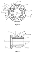
- the insert for thermoplastic support comprises a shank 1.
- the shank 1 is preferably cylindrical and oriented along a longitudinal axis A1.
- the axis A1 passes through the point C, and is perpendicular to the plane of the figure.
- oriented along the longitudinal axis A1 is meant that the generating curve of the cylinder is preferably parallel to the longitudinal axis A1.
- a head 2 is disposed at one end of the barrel 1.
- end means a longitudinal end of the barrel.
- This head 2 can be single, and can be formed in a plane perpendicular to the axis A1 of the barrel 1.
- the head 2 then extends radially relative to the outer surface of the barrel 1, and can take different forms.
- the head 2 forms a shoulder with the barrel 1, it therefore has external dimensions greater than the outer dimensions of the barrel 1 between the base of the spacer 7 and the head 2.
- the insert further comprises an element 3 projecting from the outer surface of the barrel 1.
- This element 3 is disposed between the head 2 and the end of the barrel 1 opposite the head 2.
- the protruding element 3 comprises a notch 5 defining two teeth 6a, 6b and a spacer 7 connecting the teeth 6a, 6b between them.
- the free ends of the teeth 6a, 6b are oriented towards the end of the barrel 1 opposite the head 2.
- the spacer 7 is proximal 2 of the head 2 with the interposition of a free space 8 between the spacer 7 and the head 2.
- This free space 8 can also be defined by an interposition of a separation formed by an outer surface portion of the barrel 1.
- the free space 8 is intended to receive thermoplastic material to prevent tearing of the insert by traction along the axis A1.
- the notch 5 is intended to receive thermoplastic material to prevent rotation of the insert around the axis A1.
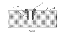
- the method of assembling an insert, as described, in a thermoplastic support 9 comprises a step in which the end of the insert opposite the head 2 of the insert is placed in contact with the thermoplastic support 9 ( figure 6 ), preferably at a hole or hole primer whose dimensions are smaller than the outer dimensions of the insert. Then, the insert is heated to a temperature capable of melting the thermoplastic material forming the support 9.
- the calories required for heating the insert can be provided by any heating system 11 capable of transmitting its calories to the insert .
- the heating system 11 may be an electric heating cartridge in thermal contact with the insert, or a system able to excite the surface electrons of the insert by induction (in this case, the insert has ferromagnetic properties).
- thermoplastic support 9 arrow F1
- This pressure can be applied after heating the insert or concomitantly with the heating of the insert.
- the molten thermoplastic material flows to cover the projecting element 3, and preferably to fill the free space 8.
- the thermoplastic support 9 and the insert are cooled to obtain a total connection between the support and the insert. Cooling can be achieved by canceling the intake of calories while placing the assembly at room temperature.
- total connection it is meant that the support 9 and the insert behave as a single piece, a relative movement of one with respect to the other is not allowed.
- the head 2 of the insert comes into contact with the support 9 and forms a stop indicating that the pressure along F1 must be interrupted.
- the head 2 has transverse dimensions greater than the transverse dimensions of the barrel and the element 3 projecting together.
- the spacer 7 comprises between the two teeth 6a, 6b, an inclined face 12 towards the barrel 1 in the direction of the end of the barrel opposite to the head 2.
- the inclined face 12 limits the insertion constraints, and to promote the displacement of said melt to fill the best free space 8 located between the spacer 7 and the head 2.
- the angle ⁇ formed by the inclined face 12 relative to the outer surface of the barrel between the spacer 7 and the head 2 is between 25 degrees and 35 degrees .
- the inclined face 12 progressively connects an upper face 13 of the element 3 protruding from a portion of the outer surface of the barrel disposed between the two teeth 6a, 6b, in other words the notch 5 has a bottom delimited by the barrel portion.
- the upper face 13 is defined as being the face of the element 3 projecting opposite and distal from a base of the element 3 projecting, said base being at the interface with the barrel 1.
- the end of the barrel 1 opposite the head 2 comprises a chamfer 14, also called cone of frustoconical shape, locally reducing the outer dimensions of said barrel 1.
- the chamfer 14 facilitates the insertion of the insert in the hole 10 during the assembly process ( figure 6 ).
- the chamfer 14 advantageously facilitates the discharge of the molten thermoplastic material along the outer surface of the insert. Therefore, the outer dimensions of the insert at its free end to which is formed the chamfer 14 are smaller than the dimensions of the hole 10 of the support 9.
- the chamfer forms an angle ⁇ between 25 degrees and 35 degrees relative to the axis A1 of the drum.
- the free ends of the teeth 6a, 6b are each provided with a portion 15a, 15b inclined towards the barrel 1 towards the end of the barrel 1 opposite the head.
- These inclined faces 15a, 15b can progressively connect the upper face 13 of the element 3 to the shaft 1.
- the inclined faces 15a, 15b of the two teeth 6a, 6b are formed in the extension of the chamfer 14. facilitate the movements of the molten thermoplastic material during assembly of the insert with the thermoplastic support 9.
- the insert has, at its end opposite the head 2, a profile allowing it to force the molten thermoplastic material towards its head 2.
- the inclined faces 15a and 15b , and the inclined face 12 of an element 3 projecting facilitate the rise of the molten thermoplastic above the element 3 protruding to fill the best free space 8.
- Each tooth 6a, 6b may comprise two longitudinal side walls 16a, 16b converging towards each other in a direction opposite to the shaft 1 (direction d 1 illustrated in FIG. figure 3 the direction d 1 being perpendicular to the longitudinal axis A1 of the barrel 1).
- the side walls are elongated in the length of the barrel, and are delimited respectively by the notch 5 and by the free space disposed around the element 3.
- the two inclined lateral walls can form an angle ⁇ 40 degrees relative to each other ( figure 5 ).
- the longitudinal side walls 16a, 16b each join a portion of the outer surface of the barrel, the upper surface 13, and optionally an inclined portion 15a, 15b associated.
- the side wall 16b delimited by the notch 5 further joins, if appropriate, the inclined face 12.
- the insert may comprise a plurality of elements 3 protruding ( figure 2 and 3 ).
- the projecting elements 3 are then staggered angularly on the outer surface of the barrel 1, two adjacent projecting elements being separated by a groove 17, preferably delimited by two longitudinal side walls of two adjacent teeth of two adjacent projecting elements, and a portion of the outer surface of the barrel 1 between the two adjacent projecting elements.
- the elements 3 projecting are integral with each other only by the barrel 1. In other words, they are spaced from each other by interposition of a separation formed by a portion of barrel 1.
- the elements 3 protruding allow thanks to their respective free spaces 8 to form after cooling of the molten thermoplastic material a retaining ring against tearing of the insert.
- the elements 3 projecting delimit a groove between their spacers 7 and the head 2.
- the grooves 17 defined above open transversely into the groove.
- the insert can be made by hot forging or cold forging. These forging techniques avoid the generation of chips or waste materials, they are therefore more economically advantageous than the techniques of bar turning or techniques requiring a resumption of machining.
- the insert can also be made by molding (foundry) with the same economic benefits.
- the insert has a hole made along its longitudinal axis.
- the hole may be blind and have an opening at the head of the insert.
- the hole may also be open and have two openings formed at the distal ends of the insert along the axis A1, that is to say at the head of the insert and at the end of the barrel opposite the head.
- the inside of the hole may be threaded so as to receive a member by screwing.
- the side walls have a curved concave surface shape whose bottom is preferably oriented along the longitudinal axis of the barrel.
- the upper wall and the inclined faces are preferably curved convex surface whose apex is preferably oriented along the longitudinal axis of the barrel.
Landscapes
- Engineering & Computer Science (AREA)
- General Engineering & Computer Science (AREA)
- Mechanical Engineering (AREA)
- Lining Or Joining Of Plastics Or The Like (AREA)
- Injection Moulding Of Plastics Or The Like (AREA)
- Standing Axle, Rod, Or Tube Structures Coupled By Welding, Adhesion, Or Deposition (AREA)
Applications Claiming Priority (1)
| Application Number | Priority Date | Filing Date | Title |
|---|---|---|---|
| FR1101208A FR2974157B1 (fr) | 2011-04-18 | 2011-04-18 | Insert pour support thermoplastique et procede d'assemblage de l'insert avec le support |
Publications (3)
| Publication Number | Publication Date |
|---|---|
| EP2514980A2 true EP2514980A2 (de) | 2012-10-24 |
| EP2514980A3 EP2514980A3 (de) | 2013-10-02 |
| EP2514980B1 EP2514980B1 (de) | 2016-05-04 |
Family
ID=45932255
Family Applications (1)
| Application Number | Title | Priority Date | Filing Date |
|---|---|---|---|
| EP12354024.7A Not-in-force EP2514980B1 (de) | 2011-04-18 | 2012-03-28 | Einsatz für thermoplastische Halterung, und Zusammenbauverfahren des Einsatzes mit der Halterung |
Country Status (5)
| Country | Link |
|---|---|
| EP (1) | EP2514980B1 (de) |
| JP (1) | JP2012225508A (de) |
| KR (1) | KR20120118441A (de) |
| CN (1) | CN102748347A (de) |
| FR (1) | FR2974157B1 (de) |
Cited By (3)
| Publication number | Priority date | Publication date | Assignee | Title |
|---|---|---|---|---|
| EP2921723A3 (de) * | 2014-02-28 | 2016-01-13 | Canon Kabushiki Kaisha | Einsatzmutter, befestigungseinheit mit der einsatzmutter und prozesskartusche mit der befestigungseinheit |
| EP2759721A3 (de) * | 2013-01-29 | 2017-07-19 | Rolls-Royce plc | Komponente mit Einsatz zur Aufnahme von Gewindebolzen |
| EP3237830A4 (de) * | 2015-05-04 | 2018-09-26 | Magpul Industries Corp. | Lageranordnung |
Families Citing this family (8)
| Publication number | Priority date | Publication date | Assignee | Title |
|---|---|---|---|---|
| EP2811177A1 (de) * | 2013-06-05 | 2014-12-10 | HILTI Aktiengesellschaft | Befestigungselement |
| CN104482018A (zh) * | 2014-12-24 | 2015-04-01 | 苏州蓝博控制技术有限公司 | 嵌装螺母 |
| TWI647389B (zh) * | 2017-12-06 | 2019-01-11 | 緯創資通股份有限公司 | 具有高拉拔力之鎖固結構以及其耐衝擊組合裝置 |
| US11577479B2 (en) | 2018-07-30 | 2023-02-14 | The Boeing Company | Locking hole plug for sealing holes in composite structures |
| US20210285476A1 (en) * | 2018-11-07 | 2021-09-16 | Hewlett-Packard Development Company, L.P. | Magnet-driven connectors |
| CN110107583A (zh) * | 2019-06-03 | 2019-08-09 | 江苏酷太厨房用品有限公司 | 一种热塑性薄板预埋螺母连接结构和连接方法及其应用 |
| CN111637129B (zh) * | 2020-05-22 | 2022-01-04 | 海信视像科技股份有限公司 | 一种电视机 |
| CN116014317B (zh) * | 2023-02-09 | 2023-06-27 | 深圳海润新能源科技有限公司 | 端盖组件、储能装置及用电设备 |
Citations (1)
| Publication number | Priority date | Publication date | Assignee | Title |
|---|---|---|---|---|
| US4046181A (en) | 1975-07-08 | 1977-09-06 | Arthur Derrick Barnsdale | Insert |
Family Cites Families (3)
| Publication number | Priority date | Publication date | Assignee | Title |
|---|---|---|---|---|
| DE4419422A1 (de) * | 1994-06-03 | 1995-12-07 | Lautenschlaeger Mepla Werke | Kunststoff-Befestigungszapfen, insbesondere für Möbelbeschläge |
| FR2762365B1 (fr) * | 1997-04-17 | 1999-07-16 | Otalu Sa | Element d'assemblage bimetallique pour des pieces plastiques |
| DE19856611A1 (de) * | 1998-12-08 | 2000-06-15 | Boellhoff Gmbh | Metallischer Einsatz |
-
2011
- 2011-04-18 FR FR1101208A patent/FR2974157B1/fr not_active Expired - Fee Related
-
2012
- 2012-03-28 EP EP12354024.7A patent/EP2514980B1/de not_active Not-in-force
- 2012-04-18 JP JP2012094561A patent/JP2012225508A/ja active Pending
- 2012-04-18 CN CN2012101819425A patent/CN102748347A/zh active Pending
- 2012-04-18 KR KR1020120040300A patent/KR20120118441A/ko not_active Withdrawn
Patent Citations (1)
| Publication number | Priority date | Publication date | Assignee | Title |
|---|---|---|---|---|
| US4046181A (en) | 1975-07-08 | 1977-09-06 | Arthur Derrick Barnsdale | Insert |
Cited By (4)
| Publication number | Priority date | Publication date | Assignee | Title |
|---|---|---|---|---|
| EP2759721A3 (de) * | 2013-01-29 | 2017-07-19 | Rolls-Royce plc | Komponente mit Einsatz zur Aufnahme von Gewindebolzen |
| EP2921723A3 (de) * | 2014-02-28 | 2016-01-13 | Canon Kabushiki Kaisha | Einsatzmutter, befestigungseinheit mit der einsatzmutter und prozesskartusche mit der befestigungseinheit |
| US10047784B2 (en) | 2014-02-28 | 2018-08-14 | Canon Kabushiki Kaisha | Insert nut, fastening unit including the insert nut, and process cartridge using the fastening unit |
| EP3237830A4 (de) * | 2015-05-04 | 2018-09-26 | Magpul Industries Corp. | Lageranordnung |
Also Published As
| Publication number | Publication date |
|---|---|
| CN102748347A (zh) | 2012-10-24 |
| KR20120118441A (ko) | 2012-10-26 |
| FR2974157A1 (fr) | 2012-10-19 |
| EP2514980B1 (de) | 2016-05-04 |
| FR2974157B1 (fr) | 2014-02-14 |
| EP2514980A3 (de) | 2013-10-02 |
| JP2012225508A (ja) | 2012-11-15 |
Similar Documents
| Publication | Publication Date | Title |
|---|---|---|
| EP2514980B1 (de) | Einsatz für thermoplastische Halterung, und Zusammenbauverfahren des Einsatzes mit der Halterung | |
| EP2425100B1 (de) | Schaufelhaltevorrichtung für ein gebläse mit einem elastomer | |
| EP2879863B1 (de) | Formelement zur vulkanisierung einer reifenlauffläche | |
| EP1481756B1 (de) | Verfahren zur Herstellung einer hohlen Turbinenschaufel | |
| EP1987932B1 (de) | Herstellungsverfahren von Formen für Spikereifen | |
| EP2140151A2 (de) | Hochleistungsfähige blindnietvorrichtung, insbesondere zur strukturellen befestigung | |
| EP2058473B1 (de) | Durch Formguss hergestellte Metalllaufradschaufel | |
| EP1954461B1 (de) | Formwerkzeug für reifenlauffläche | |
| EP2008835A1 (de) | Rad mit ausbaubarer Speiche aus Verbundmaterial | |
| FR3047801A1 (fr) | Procede de formation d'une entretoise imperdable logee dans une embase de capteur accelerometre et capteur muni d'une telle embase | |
| WO2017072430A1 (fr) | Rivet auto-perceur a haute resistance mecanique a l'arrachement et au cisaillement | |
| EP1540229B1 (de) | Klemmring | |
| EP3302916B1 (de) | Hohlprofilelement wie z. b. ein rohr aus wärmehärtbarem verbundwerkstoff und entsprechendes verfahren | |
| WO2017072429A1 (fr) | Rivet auto-perceur a haute resistance mecanique | |
| FR2667120A1 (fr) | Joint de transmission articule telescopique et procedes pour realiser un element a pistes de coullissement notamment pour un tel joint. | |
| WO2017072439A1 (fr) | Rivet auto-perceur à haute résistance mécanique avec élément de perçage ejectable | |
| EP2435686B1 (de) | Teil zur Zusammenfügung des beweglichen Teils einer einsetzbaren divergierenden Düse einer Antriebseinheit und Mechanismus für den Einsatz des beweglichen Teils | |
| FR2732417A1 (fr) | Piece d'insertion metallique pour thermoplastique, a tenue mecanique renforcee | |
| FR3058485A3 (fr) | Insert, dispositif de fixation comprenant un tel insert, et procedes de fabrication d'un tel dispositif | |
| EP3569828B1 (de) | Metalleinsatz zum aufformen zur lokalen verstärkung eines formteils eines luftfahrzeugmotors | |
| CA2401307A1 (fr) | Accessoire pour flap | |
| WO2015101746A1 (fr) | Procede pour la fixation d'un element sur un pion | |
| EP2428691A1 (de) | Einsatzblindmutter mit verformbarem Auslauf für den Gewindeschneider, und Verfahren zur Herstellung und zum Verformen des Einsatzes | |
| FR2877259A1 (fr) | Dispositif de fabrication par moulage d'une enveloppe a soufflets comprenant un noyau devissable et des moyens de retenue de l'enveloppe, et procede correspondant | |
| WO2015091344A1 (fr) | Vanne de commande avec segment d'etancheite moule comportant une bavure localisee dans un retrait |
Legal Events
| Date | Code | Title | Description |
|---|---|---|---|
| PUAI | Public reference made under article 153(3) epc to a published international application that has entered the european phase |
Free format text: ORIGINAL CODE: 0009012 |
|
| AK | Designated contracting states |
Kind code of ref document: A2 Designated state(s): AL AT BE BG CH CY CZ DE DK EE ES FI FR GB GR HR HU IE IS IT LI LT LU LV MC MK MT NL NO PL PT RO RS SE SI SK SM TR |
|
| AX | Request for extension of the european patent |
Extension state: BA ME |
|
| PUAL | Search report despatched |
Free format text: ORIGINAL CODE: 0009013 |
|
| AK | Designated contracting states |
Kind code of ref document: A3 Designated state(s): AL AT BE BG CH CY CZ DE DK EE ES FI FR GB GR HR HU IE IS IT LI LT LU LV MC MK MT NL NO PL PT RO RS SE SI SK SM TR |
|
| AX | Request for extension of the european patent |
Extension state: BA ME |
|
| RIC1 | Information provided on ipc code assigned before grant |
Ipc: F16B 37/04 20060101ALI20130827BHEP Ipc: F16B 37/12 20060101AFI20130827BHEP |
|
| 17P | Request for examination filed |
Effective date: 20131017 |
|
| RBV | Designated contracting states (corrected) |
Designated state(s): AL AT BE BG CH CY CZ DE DK EE ES FI FR GB GR HR HU IE IS IT LI LT LU LV MC MK MT NL NO PL PT RO RS SE SI SK SM TR |
|
| GRAP | Despatch of communication of intention to grant a patent |
Free format text: ORIGINAL CODE: EPIDOSNIGR1 |
|
| INTG | Intention to grant announced |
Effective date: 20151021 |
|
| GRAS | Grant fee paid |
Free format text: ORIGINAL CODE: EPIDOSNIGR3 |
|
| RAP1 | Party data changed (applicant data changed or rights of an application transferred) |
Owner name: BOLLHOFF OTALU S.A. |
|
| GRAA | (expected) grant |
Free format text: ORIGINAL CODE: 0009210 |
|
| AK | Designated contracting states |
Kind code of ref document: B1 Designated state(s): AL AT BE BG CH CY CZ DE DK EE ES FI FR GB GR HR HU IE IS IT LI LT LU LV MC MK MT NL NO PL PT RO RS SE SI SK SM TR |
|
| REG | Reference to a national code |
Ref country code: GB Ref legal event code: FG4D Free format text: NOT ENGLISH |
|
| REG | Reference to a national code |
Ref country code: CH Ref legal event code: EP |
|
| REG | Reference to a national code |
Ref country code: AT Ref legal event code: REF Ref document number: 797183 Country of ref document: AT Kind code of ref document: T Effective date: 20160515 |
|
| REG | Reference to a national code |
Ref country code: IE Ref legal event code: FG4D Free format text: LANGUAGE OF EP DOCUMENT: FRENCH |
|
| REG | Reference to a national code |
Ref country code: DE Ref legal event code: R096 Ref document number: 602012018030 Country of ref document: DE |
|
| REG | Reference to a national code |
Ref country code: NL Ref legal event code: MP Effective date: 20160504 |
|
| REG | Reference to a national code |
Ref country code: LT Ref legal event code: MG4D |
|
| PG25 | Lapsed in a contracting state [announced via postgrant information from national office to epo] |
Ref country code: FI Free format text: LAPSE BECAUSE OF FAILURE TO SUBMIT A TRANSLATION OF THE DESCRIPTION OR TO PAY THE FEE WITHIN THE PRESCRIBED TIME-LIMIT Effective date: 20160504 Ref country code: NL Free format text: LAPSE BECAUSE OF FAILURE TO SUBMIT A TRANSLATION OF THE DESCRIPTION OR TO PAY THE FEE WITHIN THE PRESCRIBED TIME-LIMIT Effective date: 20160504 Ref country code: LT Free format text: LAPSE BECAUSE OF FAILURE TO SUBMIT A TRANSLATION OF THE DESCRIPTION OR TO PAY THE FEE WITHIN THE PRESCRIBED TIME-LIMIT Effective date: 20160504 Ref country code: NO Free format text: LAPSE BECAUSE OF FAILURE TO SUBMIT A TRANSLATION OF THE DESCRIPTION OR TO PAY THE FEE WITHIN THE PRESCRIBED TIME-LIMIT Effective date: 20160804 |
|
| REG | Reference to a national code |
Ref country code: AT Ref legal event code: MK05 Ref document number: 797183 Country of ref document: AT Kind code of ref document: T Effective date: 20160504 |
|
| PG25 | Lapsed in a contracting state [announced via postgrant information from national office to epo] |
Ref country code: SE Free format text: LAPSE BECAUSE OF FAILURE TO SUBMIT A TRANSLATION OF THE DESCRIPTION OR TO PAY THE FEE WITHIN THE PRESCRIBED TIME-LIMIT Effective date: 20160504 Ref country code: HR Free format text: LAPSE BECAUSE OF FAILURE TO SUBMIT A TRANSLATION OF THE DESCRIPTION OR TO PAY THE FEE WITHIN THE PRESCRIBED TIME-LIMIT Effective date: 20160504 Ref country code: LV Free format text: LAPSE BECAUSE OF FAILURE TO SUBMIT A TRANSLATION OF THE DESCRIPTION OR TO PAY THE FEE WITHIN THE PRESCRIBED TIME-LIMIT Effective date: 20160504 Ref country code: RS Free format text: LAPSE BECAUSE OF FAILURE TO SUBMIT A TRANSLATION OF THE DESCRIPTION OR TO PAY THE FEE WITHIN THE PRESCRIBED TIME-LIMIT Effective date: 20160504 Ref country code: PT Free format text: LAPSE BECAUSE OF FAILURE TO SUBMIT A TRANSLATION OF THE DESCRIPTION OR TO PAY THE FEE WITHIN THE PRESCRIBED TIME-LIMIT Effective date: 20160905 Ref country code: GR Free format text: LAPSE BECAUSE OF FAILURE TO SUBMIT A TRANSLATION OF THE DESCRIPTION OR TO PAY THE FEE WITHIN THE PRESCRIBED TIME-LIMIT Effective date: 20160805 Ref country code: ES Free format text: LAPSE BECAUSE OF FAILURE TO SUBMIT A TRANSLATION OF THE DESCRIPTION OR TO PAY THE FEE WITHIN THE PRESCRIBED TIME-LIMIT Effective date: 20160504 |
|
| PG25 | Lapsed in a contracting state [announced via postgrant information from national office to epo] |
Ref country code: IT Free format text: LAPSE BECAUSE OF FAILURE TO SUBMIT A TRANSLATION OF THE DESCRIPTION OR TO PAY THE FEE WITHIN THE PRESCRIBED TIME-LIMIT Effective date: 20160504 |
|
| PG25 | Lapsed in a contracting state [announced via postgrant information from national office to epo] |
Ref country code: SK Free format text: LAPSE BECAUSE OF FAILURE TO SUBMIT A TRANSLATION OF THE DESCRIPTION OR TO PAY THE FEE WITHIN THE PRESCRIBED TIME-LIMIT Effective date: 20160504 Ref country code: RO Free format text: LAPSE BECAUSE OF FAILURE TO SUBMIT A TRANSLATION OF THE DESCRIPTION OR TO PAY THE FEE WITHIN THE PRESCRIBED TIME-LIMIT Effective date: 20160504 Ref country code: DK Free format text: LAPSE BECAUSE OF FAILURE TO SUBMIT A TRANSLATION OF THE DESCRIPTION OR TO PAY THE FEE WITHIN THE PRESCRIBED TIME-LIMIT Effective date: 20160504 Ref country code: CZ Free format text: LAPSE BECAUSE OF FAILURE TO SUBMIT A TRANSLATION OF THE DESCRIPTION OR TO PAY THE FEE WITHIN THE PRESCRIBED TIME-LIMIT Effective date: 20160504 Ref country code: EE Free format text: LAPSE BECAUSE OF FAILURE TO SUBMIT A TRANSLATION OF THE DESCRIPTION OR TO PAY THE FEE WITHIN THE PRESCRIBED TIME-LIMIT Effective date: 20160504 |
|
| REG | Reference to a national code |
Ref country code: DE Ref legal event code: R097 Ref document number: 602012018030 Country of ref document: DE |
|
| PG25 | Lapsed in a contracting state [announced via postgrant information from national office to epo] |
Ref country code: AT Free format text: LAPSE BECAUSE OF FAILURE TO SUBMIT A TRANSLATION OF THE DESCRIPTION OR TO PAY THE FEE WITHIN THE PRESCRIBED TIME-LIMIT Effective date: 20160504 Ref country code: SM Free format text: LAPSE BECAUSE OF FAILURE TO SUBMIT A TRANSLATION OF THE DESCRIPTION OR TO PAY THE FEE WITHIN THE PRESCRIBED TIME-LIMIT Effective date: 20160504 Ref country code: PL Free format text: LAPSE BECAUSE OF FAILURE TO SUBMIT A TRANSLATION OF THE DESCRIPTION OR TO PAY THE FEE WITHIN THE PRESCRIBED TIME-LIMIT Effective date: 20160504 |
|
| PLBE | No opposition filed within time limit |
Free format text: ORIGINAL CODE: 0009261 |
|
| STAA | Information on the status of an ep patent application or granted ep patent |
Free format text: STATUS: NO OPPOSITION FILED WITHIN TIME LIMIT |
|
| 26N | No opposition filed |
Effective date: 20170207 |
|
| PG25 | Lapsed in a contracting state [announced via postgrant information from national office to epo] |
Ref country code: SI Free format text: LAPSE BECAUSE OF FAILURE TO SUBMIT A TRANSLATION OF THE DESCRIPTION OR TO PAY THE FEE WITHIN THE PRESCRIBED TIME-LIMIT Effective date: 20160504 |
|
| REG | Reference to a national code |
Ref country code: DE Ref legal event code: R119 Ref document number: 602012018030 Country of ref document: DE |
|
| REG | Reference to a national code |
Ref country code: CH Ref legal event code: PL |
|
| GBPC | Gb: european patent ceased through non-payment of renewal fee |
Effective date: 20170328 |
|
| PG25 | Lapsed in a contracting state [announced via postgrant information from national office to epo] |
Ref country code: MC Free format text: LAPSE BECAUSE OF FAILURE TO SUBMIT A TRANSLATION OF THE DESCRIPTION OR TO PAY THE FEE WITHIN THE PRESCRIBED TIME-LIMIT Effective date: 20160504 |
|
| REG | Reference to a national code |
Ref country code: IE Ref legal event code: MM4A |
|
| REG | Reference to a national code |
Ref country code: FR Ref legal event code: ST Effective date: 20171130 |
|
| PG25 | Lapsed in a contracting state [announced via postgrant information from national office to epo] |
Ref country code: LU Free format text: LAPSE BECAUSE OF NON-PAYMENT OF DUE FEES Effective date: 20170328 Ref country code: DE Free format text: LAPSE BECAUSE OF NON-PAYMENT OF DUE FEES Effective date: 20171003 Ref country code: FR Free format text: LAPSE BECAUSE OF NON-PAYMENT OF DUE FEES Effective date: 20170331 |
|
| PG25 | Lapsed in a contracting state [announced via postgrant information from national office to epo] |
Ref country code: GB Free format text: LAPSE BECAUSE OF NON-PAYMENT OF DUE FEES Effective date: 20170328 Ref country code: IE Free format text: LAPSE BECAUSE OF NON-PAYMENT OF DUE FEES Effective date: 20170328 Ref country code: CH Free format text: LAPSE BECAUSE OF NON-PAYMENT OF DUE FEES Effective date: 20170331 Ref country code: LI Free format text: LAPSE BECAUSE OF NON-PAYMENT OF DUE FEES Effective date: 20170331 |
|
| REG | Reference to a national code |
Ref country code: BE Ref legal event code: MM Effective date: 20170331 |
|
| PG25 | Lapsed in a contracting state [announced via postgrant information from national office to epo] |
Ref country code: BE Free format text: LAPSE BECAUSE OF NON-PAYMENT OF DUE FEES Effective date: 20170331 |
|
| PG25 | Lapsed in a contracting state [announced via postgrant information from national office to epo] |
Ref country code: MT Free format text: LAPSE BECAUSE OF FAILURE TO SUBMIT A TRANSLATION OF THE DESCRIPTION OR TO PAY THE FEE WITHIN THE PRESCRIBED TIME-LIMIT Effective date: 20160504 |
|
| PG25 | Lapsed in a contracting state [announced via postgrant information from national office to epo] |
Ref country code: AL Free format text: LAPSE BECAUSE OF FAILURE TO SUBMIT A TRANSLATION OF THE DESCRIPTION OR TO PAY THE FEE WITHIN THE PRESCRIBED TIME-LIMIT Effective date: 20160504 |
|
| PG25 | Lapsed in a contracting state [announced via postgrant information from national office to epo] |
Ref country code: HU Free format text: LAPSE BECAUSE OF FAILURE TO SUBMIT A TRANSLATION OF THE DESCRIPTION OR TO PAY THE FEE WITHIN THE PRESCRIBED TIME-LIMIT; INVALID AB INITIO Effective date: 20120328 |
|
| PG25 | Lapsed in a contracting state [announced via postgrant information from national office to epo] |
Ref country code: BG Free format text: LAPSE BECAUSE OF FAILURE TO SUBMIT A TRANSLATION OF THE DESCRIPTION OR TO PAY THE FEE WITHIN THE PRESCRIBED TIME-LIMIT Effective date: 20160504 |
|
| PG25 | Lapsed in a contracting state [announced via postgrant information from national office to epo] |
Ref country code: CY Free format text: LAPSE BECAUSE OF NON-PAYMENT OF DUE FEES Effective date: 20160504 |
|
| PG25 | Lapsed in a contracting state [announced via postgrant information from national office to epo] |
Ref country code: MK Free format text: LAPSE BECAUSE OF FAILURE TO SUBMIT A TRANSLATION OF THE DESCRIPTION OR TO PAY THE FEE WITHIN THE PRESCRIBED TIME-LIMIT Effective date: 20160504 |
|
| PG25 | Lapsed in a contracting state [announced via postgrant information from national office to epo] |
Ref country code: TR Free format text: LAPSE BECAUSE OF FAILURE TO SUBMIT A TRANSLATION OF THE DESCRIPTION OR TO PAY THE FEE WITHIN THE PRESCRIBED TIME-LIMIT Effective date: 20160504 |
|
| PG25 | Lapsed in a contracting state [announced via postgrant information from national office to epo] |
Ref country code: IS Free format text: LAPSE BECAUSE OF FAILURE TO SUBMIT A TRANSLATION OF THE DESCRIPTION OR TO PAY THE FEE WITHIN THE PRESCRIBED TIME-LIMIT Effective date: 20160904 |