EP2515193B1 - Procédé destiné à éviter une collision non désirée entre un outil et une pièce usinée dans une machine-outil - Google Patents
Procédé destiné à éviter une collision non désirée entre un outil et une pièce usinée dans une machine-outil Download PDFInfo
- Publication number
- EP2515193B1 EP2515193B1 EP11162780.8A EP11162780A EP2515193B1 EP 2515193 B1 EP2515193 B1 EP 2515193B1 EP 11162780 A EP11162780 A EP 11162780A EP 2515193 B1 EP2515193 B1 EP 2515193B1
- Authority
- EP
- European Patent Office
- Prior art keywords
- tool
- workpiece
- model
- movement
- values
- Prior art date
- Legal status (The legal status is an assumption and is not a legal conclusion. Google has not performed a legal analysis and makes no representation as to the accuracy of the status listed.)
- Active
Links
Images

Classifications
-
- G—PHYSICS
- G05—CONTROLLING; REGULATING
- G05B—CONTROL OR REGULATING SYSTEMS IN GENERAL; FUNCTIONAL ELEMENTS OF SUCH SYSTEMS; MONITORING OR TESTING ARRANGEMENTS FOR SUCH SYSTEMS OR ELEMENTS
- G05B15/00—Systems controlled by a computer
- G05B15/02—Systems controlled by a computer electric
-
- G—PHYSICS
- G05—CONTROLLING; REGULATING
- G05B—CONTROL OR REGULATING SYSTEMS IN GENERAL; FUNCTIONAL ELEMENTS OF SUCH SYSTEMS; MONITORING OR TESTING ARRANGEMENTS FOR SUCH SYSTEMS OR ELEMENTS
- G05B19/00—Program-control systems
- G05B19/02—Program-control systems electric
- G05B19/18—Numerical control [NC], i.e. automatically operating machines, in particular machine tools, e.g. in a manufacturing environment, so as to execute positioning, movement or co-ordinated operations by means of program data in numerical form
- G05B19/406—Numerical control [NC], i.e. automatically operating machines, in particular machine tools, e.g. in a manufacturing environment, so as to execute positioning, movement or co-ordinated operations by means of program data in numerical form characterised by monitoring or safety
- G05B19/4061—Avoiding collision or forbidden zones
Definitions
- the invention relates to a method for avoiding an unwanted collision between a tool and a workpiece in a machine tool. Furthermore, the invention relates to a device for controlling a machine tool.
- a collision avoidance system in which a workpiece model is calculated by means of a simulation during the machining of the workpiece and a collision avoidance is realized based thereon computing time so that on the one hand a high computing power for performing such a collision avoidance system is required and on the other hand before the real machining of the workpiece can be started, the simulation must be run with a time advantage before the start of real workpiece machining, since the determination of the workpiece model in Despite the high computing power, the rule can not run at the same time as the actual machining of the workpiece.
- a method and a control for avoiding an unwanted collision between a tool and a workpiece in a machine tool are known in which a numerical control for a plurality of structural machine objects determines collision areas, wherein the collision areas are moved in dependence on machine coordinates and is checked for collision detection, whether the collision areas collide.
- the collision ranges are adapted in size as a function of the travel speed of individual axes of the machine tool and the computing time required for the collision detection.
- This object is achieved by a method for avoiding an unwanted collision between a tool and a workpiece in a machine tool, wherein when starting a processing of a part program, the determination of movement setpoints for controlling a relative movement between the tool and workpiece based on the part program and a determination of the material removal on Workpiece is started by the tool on the basis of the determined motion setpoints, wherein if after a completion or interruption of the execution of the parts program, the relative movement has come to a standstill, based on the determined material removal a workpiece model is determined, wherein the movement target values are determined based on a manual operation input, wherein Future movement target values to be expected on the basis of the desired movement values are determined, a brake end arrangement of the tool being determined on the basis of the expected future desired movement values, a tool model being determined on the basis of the brake end arrangement of the tool and a tool mold model describing the geometric shape of the tool, wherein it is checked whether the Tool model overlaps with the workpiece model, wherein in the case of a detected
- the invention does not require any safety distances between the tool and the workpiece, so that the method according to the invention can also be carried out in the case of very filigree and in particular small workpieces.
- the device for controlling a machine tool may be e.g. in the form of a CNC control, the CNC control e.g. may be in the form of a single or multiple arithmetic units, on which one or more computer programs are executed with program code for carrying out the method according to the invention.
- the arithmetic unit or arithmetic units can each have one or more processors on which the computer program or programs run.
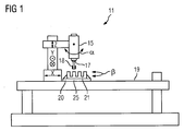
- FIG. 1 schematically a machine tool 11 is shown.
- the machine tool 11 has, in the exemplary embodiment, five machine axes, by means of which a relative movement between a tool 18, which in the exemplary embodiment is in the form of a milling cutter, and a workpiece 21 can be performed.
- the tool 18 is clamped in a tool holder 17, which is rotationally driven by a motor 15.
- the motor 15 and thus the tool 18 can be in for clarity FIG. 1 not shown drives in the X, Y and Z direction translational move and rotate in the direction ⁇ .
- the workpiece 21 can be rotated by means of a driven rotary table 25 in the direction ⁇ .
- the rotary table 25 is rotatably mounted on a stationary machine frame 19.
- the workpiece 21 is fixed by a clamping device 20 on the rotary table 25.
- the machine tool 11 thus has five machine axes, i. It is a so-called 5-axis machine tool.
- machine tool according to the invention may of course also have more or fewer than five machine axes.
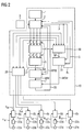
- FIG. 2 are in the form of a block diagram of an inventive device 10 for controlling a machine tool, that is shown in the context of the embodiment of the machine tool 11, and the drives for moving the tool and the workpiece.
- the device 10 has a control unit 2, which uses a part program 3 and / or a manual operation input to determine desired movement values x, y, z and ov for controlling a relative movement taking place between the tool 18 and the workpiece 21.
- the control unit 2 determines the movement target values on the basis of the part program 3, in which the movement to be performed by the tool with respect to the workpiece is defined in the form of commands.
- the movement of the tool and / or the workpiece can also be predetermined by an operator on site on the machine tool by means of a manual operation input, which is input via an operating device 1.
- the operating device 1 may be e.g. to act a handwheel and / or a keyboard.
- the part program 3 is usually generated by a CAM / CAD system and a possibly the CAM / CAD system connected downstream so-called post-processor.
- the movement of the tool 18 in relation to a stationary workpiece 21 is defined (see FIG. 3 ).
- the tool 18 is thereby moved along a movement path S.
- the desired movement values which are determined by the control unit 2, are within the scope of the exemplary embodiment in the form of position command values x, y and z, which are the movement of the tool center point TP of the tool 18 in the X, Y and Z directions. ie in 3-dimensional space, describe.
- the tool center point TP is a point preferably defined on the axis of rotation of the tool 18.
- orientation vector values ov are also determined by the control unit 2 as desired movement values, which indicate the orientation of the orientation vector OV of the tool and thus the orientation of the tool in 3-dimensional space when the tool 18 is moved on the movement path S.
- the position and orientation of the tool with respect to the workpiece on the movement path S for each point of the movement path S is defined.
- the determination of the movement setpoint values for controlling the relative movement taking place between the tool and the workpiece takes place on the basis of the part program at the start of the execution of the part program. Parallel to this, the determination of the material removal M on the workpiece is started on the basis of the determined motion setpoints.
- the desired movement values x, y, z and ov are transmitted immediately after their determination in the interpolation cycle (eg every 4 ms) to a material removal determination unit 30 which uses the movement reference values to determine the material removal M a from the machining of the workpiece by the tool Workpiece calculated.
- workpiece blank data R which describe the geometric shape of the blank (geometric shape of the workpiece before machining by the tool) of the workpiece and stored in a memory of the device 10 are further transmitted from the control unit 2 to the material removal determination unit 30. Furthermore, a tool shape model WFM describing the geometric shape of the tool, which is stored in a memory of the device 10, is also transmitted from the control unit 2 to the material removal determination unit 30. The material removal determination unit 30 then determines, based on the tool shape model WFM, the movement target values and the workpiece blank data R, by the machining of the tool on the workpiece resulting material removal M.
- the determination of the material removal M is carried out in the context of the embodiment, preferably in real time with the determination of the movement setpoints.
- the control unit 2 generates the desired movement values in the rule, preferably in a fixed time clock, the so-called interpolation clock. If, for example, motion setpoint values are generated by the control unit 2 every four milliseconds within the scope of the exemplary embodiment, then the material removal M is preferably recalculated and updated correspondingly every four milliseconds. Of course, the determination of the material removal M but also can not be done in real time.
- the workpiece model determination unit 31 uses the determined material removal M and the workpiece blank data R to determine a workpiece model WSM describing the geometric shape of the workpiece.
- the workpiece blank data R are transmitted from the control unit 2 to the workpiece model determination unit 31.
- An interruption of the execution of the part program may e.g. caused by the operator, e.g. by switching from automatic mode to manual mode.
- a grid is calculated, which connects to each other on the surface of the workpiece adjacent points, so that in the embodiment of the workpiece model WSM in the form of a so-called solid model, which through the grid is formed, is present.
- the determination of the workpiece model WSM on the basis of the material removal M and the workpiece blank data R is very computation-intensive, so that it is not processed in real time, ie. time parallel to the actual real processing on the machine can be performed.
- the control unit 2 transmits a start signal S to the workpiece model determination unit 31.
- the workpiece model determination unit 31 receives the start signal S, it determines the workpiece model WSM from the material removal M, which then no longer changes.
- the workpiece model determination unit 31 sends a blocking signal BL for a manual operation input to the control unit 2 until the workpiece model finishes the calculation is.
- the blocking signal BL As long as the blocking signal BL is present, manual operating inputs entered by an operator of the machine tool on the operating device 1, for controlling a relative movement between the tool and the workpiece, are blocked. Since the workpiece model determination unit 31 of the material removal M is finished as an input variable and the workpiece model WSM can be calculated relatively quickly on the basis of the material removal M from the workpiece model determination unit 31, the blocking of the manual operation input takes only a short time. The operator can then, ie after completed determination of the workpiece model WSM, by a manual operation input to the operating device 1 specify a relative movement between the tool and the workpiece, for example, to move the tool from the workpiece by means of machine axes. The control unit 2 determines based on the manual operation input, the movement target values x, y, z and ov in an analogous manner as previously controlled by the part program. The workpiece model WSM is transmitted to a checking unit 7.
- the movement target values are further supplied from the control unit 2 to a brake end determination unit 27 and within these to a first calculation unit 4 as input variables.
- the first calculation unit 4 of the brake end determination unit 27 determines from the current movement target values x, y, z and ov respectively expected future target movement values x ', y', z 'and ov'.
- the future movement values are determined by extrapolation from the motion setpoints currently generated by the control unit 2 and from the movement setpoints that are still in the past.
- the speed of the tool in each direction can be calculated from the current movement setpoints and the movement setpoints lying in the past, and based on this speed, an expected future position of the tool can be determined.
- the orientation of the orientation vector of the tool can also be extrapolated into the future.
- the movement setpoints are calculated in advance only by a so-called interpolation cycle of the control unit, ie usually only a few milliseconds into the future.
- the expected future movement target values thus agree very precisely with the actual future target movement values, which are generated by the control unit 2 in the next interpolation cycle.
- the expected future movement setpoints can also be further in the future than just a few milliseconds.
- the expected future movement setpoint values x ', y', z 'and ov' are then transmitted to a second calculation unit 5 of the brake end determination unit 27.
- the second calculation unit 5 uses the expected future movement setpoint values x ', y', z 'and ov' to determine a brake end arrangement BA of the tool 18.
- the brake end arrangement BA indicates the position and orientation of the tool when the relative movement between the tool and workpiece is at a standstill if a braking of the relative movement between the tool and the workpiece up to the standstill of the relative movement would be carried out on the basis of the expected future movement target values.
- the brake end arrangement BA is then transmitted to a tool model determination unit 6, which determines a tool model WM on the basis of the brake end arrangement BA and a tool shape model WMF describing the geometric shape of the tool.
- the tool model WM thus describes, in the context of the exemplary embodiment, the geometric shape of the tool, the position of the tool and the orientation of the tool.
- control unit 2 transmits the tool shape model WFM of the tool to the tool model determination unit 6.
- the tool shape model is stored in a memory of the device 10.
- the tool model WM is then transmitted to a checking unit 7, in which it is checked whether the tool model WM overlaps with the workpiece model WSM.
- the checking unit 7 determines that the tool model WM intersects with the workpiece model WSM, the checking unit 7 effects a braking of the relative movement between the tool and the workpiece until the relative movement stops. For this purpose, the checking unit 7 generates a brake signal BS in the event of an overlap of the tool model and the workpiece model and transmits this to the control unit 2, which causes a deceleration of the relative movement until the relative movement stops, via a corresponding generation of desired movement values.
- the motion command values are transmitted to a coordinate transformation unit 28, corresponding to the kinematics of the machine tool, ie the machine axes of the machine tool actually available for movement of the tool and / or the workpiece , Position command values x soll , y soll , z soll , ⁇ soll and ⁇ soll should be generated as control setpoints for controlling the movement of the drives to move the machine axes.
- the workpiece and / or the tool for realizing the relative movement between the workpiece and the tool is moved. For example, if the machine tool has a kinematics in which only the workpiece can be moved while the tool is stationary, the workpiece is moved to realize the relative movement between the workpiece and the tool.
- the position command values for the control of the drives are transmitted to the respective associated controller 8a, 8b, 8c, 8d and 8e, which drive correspondingly assigned converters 22a, 22b, 22c, 22d and 22e.
- the converters supply a respective associated electric motor 23a, 23b, 23c, 23d and 23e, each driving a machine axis.
- actual position values x is , y is , z is , ⁇ is and ⁇ is as Control values for controlling the drives to the regulations 8a, 8b, 8c, 8d and 8e transmitted.
- the method according to the invention for avoiding an unwanted collision thus operates in parallel with the movement of the tool and / or the workpiece actually carried out on the machine. It is thus no longer necessary after the start of processing the parts program, in which for a certain time a simulation is calculated in advance, before the actual real machining of the workpiece can be started. The processing time for machining the workpiece is thus reduced by the invention.
- the method preferably only determines expected movement target values over a relatively short period of time in the future, it works with high precision, so that no safety distances between workpiece and tool are necessary and thus the method is also used in the production of very small and especially filigree workpieces can.
- control unit 2 the brake assembly determination unit 27, the tool model determination unit 6, the verification unit 7, the material removal determination unit 30, the workpiece model determination unit 31, and the coordinate transformation unit 28 in the form of program code sections on one or several processors are running.
- the individual units can run on a single arithmetic unit, which may have a single or multiple processors or on several separate computing units run.
- the control unit 2, the brake assembly determination unit 27, the tool model determination unit 6, the verification unit 7, and the coordinate transformation unit 28 can run on a first computing unit and the material removal determination unit 30 and the workpiece model determination unit 31 run on a second computing unit, such as a personal computer.
- all units can also run on a single processor.
Landscapes
- Engineering & Computer Science (AREA)
- Physics & Mathematics (AREA)
- General Physics & Mathematics (AREA)
- Automation & Control Theory (AREA)
- Human Computer Interaction (AREA)
- Manufacturing & Machinery (AREA)
- General Engineering & Computer Science (AREA)
- Numerical Control (AREA)
Claims (4)
- Procédé pour empêcher une collision involontaire entre un outil ( 18 ) et une pièce ( 21 ) dans une machine-outil ( 11 ), dans lequel, au début du déroulement d'un sous-programme ( 3 ), on fait débuter la détermination de valeurs ( x, y, z, ov ) de consigne de déplacement pour la commande d'un mouvement relatif entre l'outil ( 18 ) et la pièce ( 21 ), au moyen du sous-programme ( 3 ) et une détermination de l'enlèvement ( M ) de matière de la pièce ( 21 ) par l'outil ( 18 ), au moyen des valeurs ( x, y, z, ov ) de consigne de déplacement déterminées,
caractérisé en ce que, si après un achèvement ou une interruption du déroulement du sous-programme ( 3 ), le mouvement relatif est arrivé à l'arrêt, on détermine un modèle ( WSM ) de pièce, au moyen de l'enlèvement ( M ) de matière déterminée, les valeurs ( x, y, z, ov ) de consigne de déplacement étant déterminées au moyen d'une entrée à commande manuelle, des valeurs ( x', y', z', ov' ) de consigne de déplacement à venir escomptées étant déterminées au moyen des valeurs ( x, y, z, ov ) de consigne de déplacement, un agencement ( BA ) de fin de freinage de l'outil ( 18 ) étant déterminé au moyen des valeurs ( x', y', z', ov' ) de consigne de déplacement à venir escomptées, un modèle ( WM ) d'outil étant déterminé au moyen de l'agencement ( BA ) de fin de freinage de l'outil ( 18 ) et d'un modèle ( WFM ) de forme d'outil décrivant la forme géométrique de l'outil ( 18 ), dans lequel on contrôle si le modèle ( WM ) d'outil se recoupe avec le modèle ( WSM ) de pièce, dans lequel, dans le cas de la constatation d'un recoupement, on provoque un freinage du mouvement relatif entre l'outil ( 18 ) et la pièce ( 21 ) jusqu'à l'arrêt du mouvement relatif. - Programme d'ordinateur ou programmes d'ordinateur ayant un code de programme pour effectuer un procédé suivant la revendication 1, lorsque le programme d'ordinateur ou lorsque les programmes d'ordinateur est ( sont ) exécuté ( s ) par au moins une unité de calcul.
- Dispositif de commande d'une machine-outil ( 11 ), dans lequel le dispositif a :- une unité ( 2 ) de commande, qui est constituée pour la détermination de valeurs ( x, y, z, ov ) de consigne de déplacement pour se rendre maître du déplacement relatif entre un outil ( 18 ) et une pièce ( 21 ), au moyen d'un sous-programme ( 3 ) et pour faire débuter la détermination d'un enlèvement ( M ) de matière de la pièce ( 21 ) par l'outil ( 18 ), au moyen des valeurs ( x, y, z, ov ) de consigne de déplacement déterminées au début du déroulement du sous-programme ( 3 ), dans lequel l'unité ( 2 ) de commande est constituée en outre pour la détermination de valeurs ( x, y, z, ov ) de consigne de déplacement pour se rendre maître d'un mouvement relatif entre l'outil ( 18 ) et la pièce ( 12 ) au moyen d'une entrée à commande manuelle,- une unité ( 30 ) de détermination de l'enlèvement de matière, qui est constituée pour la détermination de l'enlèvement ( M ) de matière de la pièce ( 21 ) par l'outil ( 18 ), au moyen des valeurs ( x, y, z, ov ) de consigne de déplacement déterminées,- une unité ( 31 ) de détermination d'un modèle de pièce, qui est constituée pour la détermination d'un modèle ( WSM ) de pièce au moyen de l'enlèvement ( M ) de matière déterminée, si, après un achèvement ou une interruption du déroulement du sous-programme ( 3 ), le mouvement relatif est arrivé à l'arrêt,- une unité ( 27 ) de détermination d'un agencement de fin de freinage, qui est constituée pour la détermination de valeurs ( x', y', z', ov' ) de consigne de déplacement à venir escomptées, au moyen des valeurs ( x, y, z, ov ) de déplacement, l'unité ( 27 ) de détermination d'un agencement de fin de freinage étant constituée pour déterminer, au moyen des valeurs ( x', y', z', ov' ) de consigne de déplacement à venir escomptées, un agencement ( BA ) de fin de freinage de l'outil ( 18 ),- une unité de détermination d'un modèle d'outil, qui est constituée pour la détermination d'un modèle ( WM ) d'outil, au moyen de l'agencement ( BA ) de fin de freinage et d'un modèle ( WFM ) de forme d'outil décrivant la forme géométrique de l'outil ( 18 ) et- une unité ( 7 ) de contrôle, qui est constituée pour contrôler si le modèle ( WM ) d'outil se recoupe avec le modèle ( WSM ) de pièce, l'unité ( 7 ) de contrôle étant constituée pour, dans le cas de la constatation d'un recoupement, provoquer un freinage du mouvement relatif entre l'outil ( 18 ) et la pièce ( 21 ) jusqu'à l'arrêt du mouvement relatif.
- Machine-outil ( 11 ), dans laquelle la machine-outil ( 11 ) a un dispositif suivant la revendication 3.
Priority Applications (4)
| Application Number | Priority Date | Filing Date | Title |
|---|---|---|---|
| EP11162780.8A EP2515193B1 (fr) | 2011-04-18 | 2011-04-18 | Procédé destiné à éviter une collision non désirée entre un outil et une pièce usinée dans une machine-outil |
| JP2012093041A JP5474122B2 (ja) | 2011-04-18 | 2012-04-16 | 工作機械における工具と工作物との間の意図しない衝突の回避方法 |
| CN201210115500.0A CN102749886B (zh) | 2011-04-18 | 2012-04-18 | 用于在机床中避免工具和工件之间不期望的碰撞的方法 |
| US13/449,838 US8630732B2 (en) | 2011-04-18 | 2012-04-18 | Method for avoiding an unwanted collision between a tool and a workpiece in a machine tool |
Applications Claiming Priority (1)
| Application Number | Priority Date | Filing Date | Title |
|---|---|---|---|
| EP11162780.8A EP2515193B1 (fr) | 2011-04-18 | 2011-04-18 | Procédé destiné à éviter une collision non désirée entre un outil et une pièce usinée dans une machine-outil |
Publications (2)
| Publication Number | Publication Date |
|---|---|
| EP2515193A1 EP2515193A1 (fr) | 2012-10-24 |
| EP2515193B1 true EP2515193B1 (fr) | 2014-04-02 |
Family
ID=44764321
Family Applications (1)
| Application Number | Title | Priority Date | Filing Date |
|---|---|---|---|
| EP11162780.8A Active EP2515193B1 (fr) | 2011-04-18 | 2011-04-18 | Procédé destiné à éviter une collision non désirée entre un outil et une pièce usinée dans une machine-outil |
Country Status (4)
| Country | Link |
|---|---|
| US (1) | US8630732B2 (fr) |
| EP (1) | EP2515193B1 (fr) |
| JP (1) | JP5474122B2 (fr) |
| CN (1) | CN102749886B (fr) |
Families Citing this family (10)
| Publication number | Priority date | Publication date | Assignee | Title |
|---|---|---|---|---|
| JP6175249B2 (ja) * | 2013-02-26 | 2017-08-02 | 三菱重工工作機械株式会社 | 工作機械の衝突回避システム |
| EP2853354B1 (fr) * | 2013-09-27 | 2018-05-16 | Siemens Aktiengesellschaft | Régulation de position avec prévention de collision et adaptation d'un modèle de machine à la machine réelle |
| ITMI20131698A1 (it) | 2013-10-15 | 2015-04-16 | Pirelli Tyre Spa | Metodo ed apparecchiatura per controllare la deposizione di componenti di pneumatici su tamburi di formatura |
| JP5845300B2 (ja) * | 2014-03-07 | 2016-01-20 | ファナック株式会社 | 誤った軸指令をチェックする数値制御装置 |
| US10549397B1 (en) * | 2017-12-19 | 2020-02-04 | Haas Automation, Inc. | Dynamic conveyor control system |
| TWI656942B (zh) * | 2018-01-12 | 2019-04-21 | 財團法人工業技術研究院 | 工具機防碰撞方法及工具機防碰撞系統 |
| EP3579066B1 (fr) * | 2018-06-06 | 2026-01-28 | Agie Charmilles SA | Procédé de protection contre la collision |
| EP3690573B1 (fr) * | 2019-01-30 | 2021-08-18 | Siemens Aktiengesellschaft | Commande d'une machine-outil |
| TWI716849B (zh) | 2019-04-10 | 2021-01-21 | 財團法人工業技術研究院 | 預先檢測加工路徑碰撞方法及系統 |
| JPWO2023007664A1 (fr) * | 2021-07-29 | 2023-02-02 |
Family Cites Families (19)
| Publication number | Priority date | Publication date | Assignee | Title |
|---|---|---|---|---|
| JPS6316303A (ja) * | 1986-07-09 | 1988-01-23 | Mitsubishi Electric Corp | 数値制御装置 |
| JPH0659715A (ja) * | 1991-03-09 | 1994-03-04 | Brother Ind Ltd | 数値制御方法および装置 |
| JPH0639677A (ja) * | 1992-07-24 | 1994-02-15 | Okuma Mach Works Ltd | 数値制御データ作成装置 |
| US5835684A (en) * | 1994-11-09 | 1998-11-10 | Amada Company, Ltd. | Method for planning/controlling robot motion |
| JP3745526B2 (ja) * | 1998-03-02 | 2006-02-15 | 日産自動車株式会社 | Ncデータ作成用荒加工中間形状モデル生成装置 |
| JP3180805B2 (ja) * | 1999-07-16 | 2001-06-25 | 三菱電機株式会社 | 数値制御工作機械 |
| DE19960834B4 (de) * | 1999-12-16 | 2006-10-26 | Agie S.A., Losone | Verfahren und Vorrichtung zur Störungserfassung, insbesondere zur Kollisionserfassung, im Antriebssystem einer numerisch gesteuerten Werkzeugmaschine |
| DE60035129T2 (de) * | 2000-06-30 | 2008-02-07 | Okuma Corp., Nagoya | Vorrichtung und verfahren zur maschinellen simulation für numerisch gesteuerte bearbeitungsweisen |
| DE10114811A1 (de) * | 2001-03-26 | 2002-10-10 | Volkswagen Ag | System und Verfahren zur Erstellung von mehrachsigen Bearbeitungs-Vorgängen an Werkstücken |
| JP2006163665A (ja) * | 2004-12-06 | 2006-06-22 | Toshiba Corp | 数値制御加工機の数値制御情報確認装置および方法 |
| JP2007249671A (ja) * | 2006-03-16 | 2007-09-27 | Nakamura Tome Precision Ind Co Ltd | 工作機械の衝突防止方法 |
| WO2008025577A1 (fr) * | 2006-05-30 | 2008-03-06 | Siemens Aktiengesellschaft | Procédé et dispositif destinés à surveiller les collisions d'un élément de machine avec un objet dans une machine-outil et/ou dans une machine de production et/ou dans une machine qui se présente sous le forme d'un robot |
| JP4838647B2 (ja) | 2006-07-05 | 2011-12-14 | 株式会社森精機製作所 | 工作機械の制御装置 |
| JP4298770B2 (ja) | 2007-08-28 | 2009-07-22 | ファナック株式会社 | 干渉チェック機能を備えた数値制御装置 |
| DE102007045593A1 (de) * | 2007-09-14 | 2009-03-26 | Index-Werke Gmbh & Co. Kg Hahn & Tessky | Virtuelle Werkzeugmaschine zur Darstellung von Aktionen von Bearbeitungseinheiten einer realen Werkzeugmaschine |
| DE102009029062A1 (de) * | 2008-09-05 | 2010-03-11 | Mori Seiki Co., Ltd., Yamatokoriyama-shi | Verfahren und Vorrichtung zur Bearbeitungszustandsüberwachung |
| JP5139230B2 (ja) * | 2008-10-06 | 2013-02-06 | オークマ株式会社 | 数値制御装置における衝突防止装置 |
| JP5394093B2 (ja) * | 2009-02-13 | 2014-01-22 | ファナック株式会社 | 工具折損検出機能を有する工作機械を制御する数値制御装置 |
| DE102009015934A1 (de) * | 2009-04-02 | 2010-10-07 | Dmg Electronics Gmbh | Verfahren und Vorrichtung zum Erzeugen von Steuerdaten zum Steuern eines Werkzeugs an einer Werkzeugmaschine |
-
2011
- 2011-04-18 EP EP11162780.8A patent/EP2515193B1/fr active Active
-
2012
- 2012-04-16 JP JP2012093041A patent/JP5474122B2/ja active Active
- 2012-04-18 US US13/449,838 patent/US8630732B2/en active Active
- 2012-04-18 CN CN201210115500.0A patent/CN102749886B/zh active Active
Also Published As
| Publication number | Publication date |
|---|---|
| EP2515193A1 (fr) | 2012-10-24 |
| JP5474122B2 (ja) | 2014-04-16 |
| CN102749886B (zh) | 2014-10-22 |
| US8630732B2 (en) | 2014-01-14 |
| US20130103180A1 (en) | 2013-04-25 |
| JP2012226749A (ja) | 2012-11-15 |
| CN102749886A (zh) | 2012-10-24 |
Similar Documents
| Publication | Publication Date | Title |
|---|---|---|
| EP2515193B1 (fr) | Procédé destiné à éviter une collision non désirée entre un outil et une pièce usinée dans une machine-outil | |
| DE102008001011B4 (de) | Numerische Steuervorrichtung | |
| DE112009005397B4 (de) | Numerische Steuervorrichtung | |
| DE102011108282B4 (de) | Numerische Steuerung für eine Mehrachsenmaschine zum Bearbeiten einer geneigten Bearbeitungsebene | |
| DE3806966C2 (fr) | ||
| DE102017004366B4 (de) | Numerische Steuervorrichtung | |
| EP2008752A1 (fr) | Machine destinée au traitement de pièces à usiner et procédé destiné au traitement mécanique de pièces à usiner | |
| DE102020124734A1 (de) | Simulationsgerät | |
| EP3056322B1 (fr) | Procédé et système de fonctionnement d'une machine multiaxiale, en particulier un robot | |
| EP0334044B1 (fr) | Système de contrôle pour empêcher la collision de deux couteaux | |
| EP2650741B1 (fr) | Machine-outil | |
| DE102005037779B4 (de) | Numerische Steuereinheit | |
| WO2002020213A2 (fr) | Machine-outil | |
| EP2515192B1 (fr) | Procédé destiné à éviter une collision non désirée entre un outil et une pièce usinée dans une machine-outil | |
| DE102018009999B9 (de) | Numerische steuerung | |
| DE102017222137B4 (de) | Numerische Steuervorrichtung | |
| DE102016014179B4 (de) | Numerische Steuerung | |
| EP3300521B1 (fr) | Procede d'alignement pour pieces | |
| DE102020118357B4 (de) | Steuerung für werkzeugmaschine und steuersystem | |
| DE102015012147B4 (de) | Numerische Steuervorrichtung | |
| DE112021000558T5 (de) | Numerische Steuerung | |
| DE102017011602B4 (de) | Numerische Steuerung | |
| EP3890928B1 (fr) | Procédé à limitation de la force d'au moins un élément d'une machine de production en fonctionnement manuel | |
| EP3993960B1 (fr) | Arrêt d'une machine de production sur une voie sans collision | |
| EP3944931A1 (fr) | Système d'évitement de collisions pourvu de l'intelligence artificielle |
Legal Events
| Date | Code | Title | Description |
|---|---|---|---|
| PUAI | Public reference made under article 153(3) epc to a published international application that has entered the european phase |
Free format text: ORIGINAL CODE: 0009012 |
|
| AK | Designated contracting states |
Kind code of ref document: A1 Designated state(s): AL AT BE BG CH CY CZ DE DK EE ES FI FR GB GR HR HU IE IS IT LI LT LU LV MC MK MT NL NO PL PT RO RS SE SI SK SM TR |
|
| AX | Request for extension of the european patent |
Extension state: BA ME |
|
| RAP1 | Party data changed (applicant data changed or rights of an application transferred) |
Owner name: SIEMENS AKTIENGESELLSCHAFT |
|
| 17P | Request for examination filed |
Effective date: 20130424 |
|
| GRAP | Despatch of communication of intention to grant a patent |
Free format text: ORIGINAL CODE: EPIDOSNIGR1 |
|
| RIC1 | Information provided on ipc code assigned before grant |
Ipc: G05B 19/4061 20060101AFI20131015BHEP Ipc: G05B 15/02 20060101ALI20131015BHEP |
|
| INTG | Intention to grant announced |
Effective date: 20131031 |
|
| GRAS | Grant fee paid |
Free format text: ORIGINAL CODE: EPIDOSNIGR3 |
|
| GRAA | (expected) grant |
Free format text: ORIGINAL CODE: 0009210 |
|
| AK | Designated contracting states |
Kind code of ref document: B1 Designated state(s): AL AT BE BG CH CY CZ DE DK EE ES FI FR GB GR HR HU IE IS IT LI LT LU LV MC MK MT NL NO PL PT RO RS SE SI SK SM TR |
|
| REG | Reference to a national code |
Ref country code: GB Ref legal event code: FG4D Free format text: NOT ENGLISH |
|
| REG | Reference to a national code |
Ref country code: CH Ref legal event code: EP Ref country code: AT Ref legal event code: REF Ref document number: 660474 Country of ref document: AT Kind code of ref document: T Effective date: 20140415 |
|
| REG | Reference to a national code |
Ref country code: IE Ref legal event code: FG4D Free format text: LANGUAGE OF EP DOCUMENT: GERMAN |
|
| REG | Reference to a national code |
Ref country code: DE Ref legal event code: R096 Ref document number: 502011002575 Country of ref document: DE Effective date: 20140515 |
|
| REG | Reference to a national code |
Ref country code: NL Ref legal event code: VDEP Effective date: 20140402 |
|
| REG | Reference to a national code |
Ref country code: LT Ref legal event code: MG4D |
|
| PG25 | Lapsed in a contracting state [announced via postgrant information from national office to epo] |
Ref country code: NL Free format text: LAPSE BECAUSE OF FAILURE TO SUBMIT A TRANSLATION OF THE DESCRIPTION OR TO PAY THE FEE WITHIN THE PRESCRIBED TIME-LIMIT Effective date: 20140402 Ref country code: CZ Free format text: LAPSE BECAUSE OF FAILURE TO SUBMIT A TRANSLATION OF THE DESCRIPTION OR TO PAY THE FEE WITHIN THE PRESCRIBED TIME-LIMIT Effective date: 20140402 Ref country code: IS Free format text: LAPSE BECAUSE OF FAILURE TO SUBMIT A TRANSLATION OF THE DESCRIPTION OR TO PAY THE FEE WITHIN THE PRESCRIBED TIME-LIMIT Effective date: 20140802 Ref country code: NO Free format text: LAPSE BECAUSE OF FAILURE TO SUBMIT A TRANSLATION OF THE DESCRIPTION OR TO PAY THE FEE WITHIN THE PRESCRIBED TIME-LIMIT Effective date: 20140702 Ref country code: FI Free format text: LAPSE BECAUSE OF FAILURE TO SUBMIT A TRANSLATION OF THE DESCRIPTION OR TO PAY THE FEE WITHIN THE PRESCRIBED TIME-LIMIT Effective date: 20140402 Ref country code: CY Free format text: LAPSE BECAUSE OF FAILURE TO SUBMIT A TRANSLATION OF THE DESCRIPTION OR TO PAY THE FEE WITHIN THE PRESCRIBED TIME-LIMIT Effective date: 20140402 Ref country code: LT Free format text: LAPSE BECAUSE OF FAILURE TO SUBMIT A TRANSLATION OF THE DESCRIPTION OR TO PAY THE FEE WITHIN THE PRESCRIBED TIME-LIMIT Effective date: 20140402 Ref country code: GR Free format text: LAPSE BECAUSE OF FAILURE TO SUBMIT A TRANSLATION OF THE DESCRIPTION OR TO PAY THE FEE WITHIN THE PRESCRIBED TIME-LIMIT Effective date: 20140703 Ref country code: BG Free format text: LAPSE BECAUSE OF FAILURE TO SUBMIT A TRANSLATION OF THE DESCRIPTION OR TO PAY THE FEE WITHIN THE PRESCRIBED TIME-LIMIT Effective date: 20140702 |
|
| PG25 | Lapsed in a contracting state [announced via postgrant information from national office to epo] |
Ref country code: PL Free format text: LAPSE BECAUSE OF FAILURE TO SUBMIT A TRANSLATION OF THE DESCRIPTION OR TO PAY THE FEE WITHIN THE PRESCRIBED TIME-LIMIT Effective date: 20140402 Ref country code: ES Free format text: LAPSE BECAUSE OF FAILURE TO SUBMIT A TRANSLATION OF THE DESCRIPTION OR TO PAY THE FEE WITHIN THE PRESCRIBED TIME-LIMIT Effective date: 20140402 Ref country code: HR Free format text: LAPSE BECAUSE OF FAILURE TO SUBMIT A TRANSLATION OF THE DESCRIPTION OR TO PAY THE FEE WITHIN THE PRESCRIBED TIME-LIMIT Effective date: 20140402 Ref country code: LV Free format text: LAPSE BECAUSE OF FAILURE TO SUBMIT A TRANSLATION OF THE DESCRIPTION OR TO PAY THE FEE WITHIN THE PRESCRIBED TIME-LIMIT Effective date: 20140402 Ref country code: RS Free format text: LAPSE BECAUSE OF FAILURE TO SUBMIT A TRANSLATION OF THE DESCRIPTION OR TO PAY THE FEE WITHIN THE PRESCRIBED TIME-LIMIT Effective date: 20140402 Ref country code: SE Free format text: LAPSE BECAUSE OF FAILURE TO SUBMIT A TRANSLATION OF THE DESCRIPTION OR TO PAY THE FEE WITHIN THE PRESCRIBED TIME-LIMIT Effective date: 20140402 |
|
| REG | Reference to a national code |
Ref country code: CH Ref legal event code: PL |
|
| PG25 | Lapsed in a contracting state [announced via postgrant information from national office to epo] |
Ref country code: PT Free format text: LAPSE BECAUSE OF FAILURE TO SUBMIT A TRANSLATION OF THE DESCRIPTION OR TO PAY THE FEE WITHIN THE PRESCRIBED TIME-LIMIT Effective date: 20140804 |
|
| REG | Reference to a national code |
Ref country code: DE Ref legal event code: R097 Ref document number: 502011002575 Country of ref document: DE |
|
| REG | Reference to a national code |
Ref country code: IE Ref legal event code: MM4A |
|
| PG25 | Lapsed in a contracting state [announced via postgrant information from national office to epo] |
Ref country code: CH Free format text: LAPSE BECAUSE OF NON-PAYMENT OF DUE FEES Effective date: 20140430 Ref country code: RO Free format text: LAPSE BECAUSE OF FAILURE TO SUBMIT A TRANSLATION OF THE DESCRIPTION OR TO PAY THE FEE WITHIN THE PRESCRIBED TIME-LIMIT Effective date: 20140402 Ref country code: LI Free format text: LAPSE BECAUSE OF NON-PAYMENT OF DUE FEES Effective date: 20140430 Ref country code: SK Free format text: LAPSE BECAUSE OF FAILURE TO SUBMIT A TRANSLATION OF THE DESCRIPTION OR TO PAY THE FEE WITHIN THE PRESCRIBED TIME-LIMIT Effective date: 20140402 Ref country code: EE Free format text: LAPSE BECAUSE OF FAILURE TO SUBMIT A TRANSLATION OF THE DESCRIPTION OR TO PAY THE FEE WITHIN THE PRESCRIBED TIME-LIMIT Effective date: 20140402 Ref country code: MC Free format text: LAPSE BECAUSE OF FAILURE TO SUBMIT A TRANSLATION OF THE DESCRIPTION OR TO PAY THE FEE WITHIN THE PRESCRIBED TIME-LIMIT Effective date: 20140402 Ref country code: DK Free format text: LAPSE BECAUSE OF FAILURE TO SUBMIT A TRANSLATION OF THE DESCRIPTION OR TO PAY THE FEE WITHIN THE PRESCRIBED TIME-LIMIT Effective date: 20140402 |
|
| PLBE | No opposition filed within time limit |
Free format text: ORIGINAL CODE: 0009261 |
|
| STAA | Information on the status of an ep patent application or granted ep patent |
Free format text: STATUS: NO OPPOSITION FILED WITHIN TIME LIMIT |
|
| 26N | No opposition filed |
Effective date: 20150106 |
|
| REG | Reference to a national code |
Ref country code: FR Ref legal event code: ST Effective date: 20150212 |
|
| PG25 | Lapsed in a contracting state [announced via postgrant information from national office to epo] |
Ref country code: IT Free format text: LAPSE BECAUSE OF FAILURE TO SUBMIT A TRANSLATION OF THE DESCRIPTION OR TO PAY THE FEE WITHIN THE PRESCRIBED TIME-LIMIT Effective date: 20140402 |
|
| REG | Reference to a national code |
Ref country code: DE Ref legal event code: R097 Ref document number: 502011002575 Country of ref document: DE Effective date: 20150106 |
|
| PG25 | Lapsed in a contracting state [announced via postgrant information from national office to epo] |
Ref country code: IE Free format text: LAPSE BECAUSE OF NON-PAYMENT OF DUE FEES Effective date: 20140418 |
|
| PG25 | Lapsed in a contracting state [announced via postgrant information from national office to epo] |
Ref country code: FR Free format text: LAPSE BECAUSE OF NON-PAYMENT OF DUE FEES Effective date: 20140602 Ref country code: RS Free format text: LAPSE BECAUSE OF FAILURE TO SUBMIT A TRANSLATION OF THE DESCRIPTION OR TO PAY THE FEE WITHIN THE PRESCRIBED TIME-LIMIT Effective date: 20141119 |
|
| PG25 | Lapsed in a contracting state [announced via postgrant information from national office to epo] |
Ref country code: SI Free format text: LAPSE BECAUSE OF FAILURE TO SUBMIT A TRANSLATION OF THE DESCRIPTION OR TO PAY THE FEE WITHIN THE PRESCRIBED TIME-LIMIT Effective date: 20140402 |
|
| GBPC | Gb: european patent ceased through non-payment of renewal fee |
Effective date: 20150418 |
|
| PG25 | Lapsed in a contracting state [announced via postgrant information from national office to epo] |
Ref country code: GB Free format text: LAPSE BECAUSE OF NON-PAYMENT OF DUE FEES Effective date: 20150418 |
|
| PG25 | Lapsed in a contracting state [announced via postgrant information from national office to epo] |
Ref country code: MT Free format text: LAPSE BECAUSE OF FAILURE TO SUBMIT A TRANSLATION OF THE DESCRIPTION OR TO PAY THE FEE WITHIN THE PRESCRIBED TIME-LIMIT Effective date: 20140402 |
|
| PG25 | Lapsed in a contracting state [announced via postgrant information from national office to epo] |
Ref country code: SM Free format text: LAPSE BECAUSE OF FAILURE TO SUBMIT A TRANSLATION OF THE DESCRIPTION OR TO PAY THE FEE WITHIN THE PRESCRIBED TIME-LIMIT Effective date: 20140402 |
|
| PG25 | Lapsed in a contracting state [announced via postgrant information from national office to epo] |
Ref country code: BE Free format text: LAPSE BECAUSE OF FAILURE TO SUBMIT A TRANSLATION OF THE DESCRIPTION OR TO PAY THE FEE WITHIN THE PRESCRIBED TIME-LIMIT Effective date: 20140430 Ref country code: TR Free format text: LAPSE BECAUSE OF FAILURE TO SUBMIT A TRANSLATION OF THE DESCRIPTION OR TO PAY THE FEE WITHIN THE PRESCRIBED TIME-LIMIT Effective date: 20140402 Ref country code: LU Free format text: LAPSE BECAUSE OF NON-PAYMENT OF DUE FEES Effective date: 20140418 Ref country code: HU Free format text: LAPSE BECAUSE OF FAILURE TO SUBMIT A TRANSLATION OF THE DESCRIPTION OR TO PAY THE FEE WITHIN THE PRESCRIBED TIME-LIMIT; INVALID AB INITIO Effective date: 20110418 |
|
| REG | Reference to a national code |
Ref country code: AT Ref legal event code: MM01 Ref document number: 660474 Country of ref document: AT Kind code of ref document: T Effective date: 20160418 |
|
| PG25 | Lapsed in a contracting state [announced via postgrant information from national office to epo] |
Ref country code: AT Free format text: LAPSE BECAUSE OF NON-PAYMENT OF DUE FEES Effective date: 20160418 |
|
| PG25 | Lapsed in a contracting state [announced via postgrant information from national office to epo] |
Ref country code: MK Free format text: LAPSE BECAUSE OF FAILURE TO SUBMIT A TRANSLATION OF THE DESCRIPTION OR TO PAY THE FEE WITHIN THE PRESCRIBED TIME-LIMIT Effective date: 20140402 |
|
| PG25 | Lapsed in a contracting state [announced via postgrant information from national office to epo] |
Ref country code: AL Free format text: LAPSE BECAUSE OF FAILURE TO SUBMIT A TRANSLATION OF THE DESCRIPTION OR TO PAY THE FEE WITHIN THE PRESCRIBED TIME-LIMIT Effective date: 20140402 |
|
| PGFP | Annual fee paid to national office [announced via postgrant information from national office to epo] |
Ref country code: DE Payment date: 20250620 Year of fee payment: 15 |