EP3300521B1 - Procede d'alignement pour pieces - Google Patents
Procede d'alignement pour pieces Download PDFInfo
- Publication number
- EP3300521B1 EP3300521B1 EP16747740.5A EP16747740A EP3300521B1 EP 3300521 B1 EP3300521 B1 EP 3300521B1 EP 16747740 A EP16747740 A EP 16747740A EP 3300521 B1 EP3300521 B1 EP 3300521B1
- Authority
- EP
- European Patent Office
- Prior art keywords
- workpiece
- rigid transformation
- machine
- parameter
- axes
- Prior art date
- Legal status (The legal status is an assumption and is not a legal conclusion. Google has not performed a legal analysis and makes no representation as to the accuracy of the status listed.)
- Active
Links
Images




Classifications
-
- G—PHYSICS
- G05—CONTROLLING; REGULATING
- G05B—CONTROL OR REGULATING SYSTEMS IN GENERAL; FUNCTIONAL ELEMENTS OF SUCH SYSTEMS; MONITORING OR TESTING ARRANGEMENTS FOR SUCH SYSTEMS OR ELEMENTS
- G05B19/00—Program-control systems
- G05B19/02—Program-control systems electric
- G05B19/18—Numerical control [NC], i.e. automatically operating machines, in particular machine tools, e.g. in a manufacturing environment, so as to execute positioning, movement or co-ordinated operations by means of program data in numerical form
- G05B19/408—Numerical control [NC], i.e. automatically operating machines, in particular machine tools, e.g. in a manufacturing environment, so as to execute positioning, movement or co-ordinated operations by means of program data in numerical form characterised by data handling or data format, e.g. reading, buffering or conversion of data
- G05B19/4086—Coordinate conversions; Other special calculations
-
- G—PHYSICS
- G05—CONTROLLING; REGULATING
- G05B—CONTROL OR REGULATING SYSTEMS IN GENERAL; FUNCTIONAL ELEMENTS OF SUCH SYSTEMS; MONITORING OR TESTING ARRANGEMENTS FOR SUCH SYSTEMS OR ELEMENTS
- G05B19/00—Program-control systems
- G05B19/02—Program-control systems electric
- G05B19/18—Numerical control [NC], i.e. automatically operating machines, in particular machine tools, e.g. in a manufacturing environment, so as to execute positioning, movement or co-ordinated operations by means of program data in numerical form
- G05B19/406—Numerical control [NC], i.e. automatically operating machines, in particular machine tools, e.g. in a manufacturing environment, so as to execute positioning, movement or co-ordinated operations by means of program data in numerical form characterised by monitoring or safety
- G05B19/4068—Verifying part program on screen, by drawing or other means
-
- G—PHYSICS
- G05—CONTROLLING; REGULATING
- G05B—CONTROL OR REGULATING SYSTEMS IN GENERAL; FUNCTIONAL ELEMENTS OF SUCH SYSTEMS; MONITORING OR TESTING ARRANGEMENTS FOR SUCH SYSTEMS OR ELEMENTS
- G05B2219/00—Program-control systems
- G05B2219/30—Nc systems
- G05B2219/32—Operator till task planning
- G05B2219/32017—Adapt real process as function of changing simulation model, changing for better results
-
- G—PHYSICS
- G05—CONTROLLING; REGULATING
- G05B—CONTROL OR REGULATING SYSTEMS IN GENERAL; FUNCTIONAL ELEMENTS OF SUCH SYSTEMS; MONITORING OR TESTING ARRANGEMENTS FOR SUCH SYSTEMS OR ELEMENTS
- G05B2219/00—Program-control systems
- G05B2219/30—Nc systems
- G05B2219/39—Robotics, robotics to robotics hand
- G05B2219/39361—Minimize time-energy cost
-
- G—PHYSICS
- G05—CONTROLLING; REGULATING
- G05B—CONTROL OR REGULATING SYSTEMS IN GENERAL; FUNCTIONAL ELEMENTS OF SUCH SYSTEMS; MONITORING OR TESTING ARRANGEMENTS FOR SUCH SYSTEMS OR ELEMENTS
- G05B2219/00—Program-control systems
- G05B2219/30—Nc systems
- G05B2219/50—Machine tool, machine tool null till machine tool work handling
- G05B2219/50052—Orienting workpiece relative to tool
-
- G—PHYSICS
- G05—CONTROLLING; REGULATING
- G05B—CONTROL OR REGULATING SYSTEMS IN GENERAL; FUNCTIONAL ELEMENTS OF SUCH SYSTEMS; MONITORING OR TESTING ARRANGEMENTS FOR SUCH SYSTEMS OR ELEMENTS
- G05B2219/00—Program-control systems
- G05B2219/30—Nc systems
- G05B2219/50—Machine tool, machine tool null till machine tool work handling
- G05B2219/50148—Workpiece, setup of component, workpiece
-
- G—PHYSICS
- G05—CONTROLLING; REGULATING
- G05B—CONTROL OR REGULATING SYSTEMS IN GENERAL; FUNCTIONAL ELEMENTS OF SUCH SYSTEMS; MONITORING OR TESTING ARRANGEMENTS FOR SUCH SYSTEMS OR ELEMENTS
- G05B2219/00—Program-control systems
- G05B2219/30—Nc systems
- G05B2219/50—Machine tool, machine tool null till machine tool work handling
- G05B2219/50149—Find orientation workpiece which maximizes number of faces machined in one setup
-
- G—PHYSICS
- G05—CONTROLLING; REGULATING
- G05B—CONTROL OR REGULATING SYSTEMS IN GENERAL; FUNCTIONAL ELEMENTS OF SUCH SYSTEMS; MONITORING OR TESTING ARRANGEMENTS FOR SUCH SYSTEMS OR ELEMENTS
- G05B2219/00—Program-control systems
- G05B2219/30—Nc systems
- G05B2219/50—Machine tool, machine tool null till machine tool work handling
- G05B2219/50151—Orient, translate, align workpiece to fit position assumed in program
Definitions
- the invention relates to a method for aligning a workpiece, as well as a suitable program, a suitable control unit, and a corresponding production machine.
- machining processes for workpieces known in which an NC or CNC-controlled tool or tool replacement, such as a laser dot or a printing tip, is guided relative to the workpiece along a path.
- the tool and / or the workpiece is driven along its Hauptachsausschen by a plurality of drive means whose structure determine the achievable machining performance.
- a time savings can be achieved by a modified spatial orientation of a workpiece to be machined with respect to the alignment of the major axes during processing. For this example, the workpiece is rotated rotated by a certain angle. The corresponding angle is determined by manual trial by a user.
- a work piece-fixed processing path is provided by a control unit of a production machine, which a tool of the production machine has to run to produce the desired product.
- the workpiece-fixed processing path is in this case based on a workpiece reference point and defined in an associated workpiece axis system.
- the workpiece-fixed machining path is thus defined in a body-fixed reference system.
- a rigid transformation of the positioning of the workpiece is selected. Under the rigid transformation here is the position of the workpiece reference point relative to the production machine reference point in the associated tool axis system to understand.
- the rigid transformation further comprises the alignment of the workpiece axis system in the production machine axis system.
- the selection of the rigid transformation is made by a program executed in the control unit of the tool control machine.
- the traversing of the workpiece-fixed machining path is carried out taking into account the rigid transformation of the workpiece positioning.
- at least one associated control command for at least one drive means of the production machine is calculated and stored.
- the determined at least one control command is evaluated, so that a time-resolved stress of the drive means of the production machine can be seen. Based on this, at least one process variable is determined, which characterizes the departure of the workpiece-fixed machining path during machining.
- the described steps are repeated by modifying the rigid transformation of the workpiece positioning and in each case the associated process variable is determined.
- the process steps are repeated until the at least one process variable reaches a desired target value.
- the method according to the invention makes it possible to evaluate a large number of orientations of the workpiece in a short time and to select a suitable alignment.
- the process variable to be evaluated can be selected by the user, so that an optimization on a variety of aspects is possible.
- the method according to the invention uses, with the processing path, information necessary for processing the workpiece, which is present anyway.
- the simulation of the processing path subjected to the rigid transformation takes place in a software module which is present in any case in a control unit of a modern production machine.
- the invention is based on the surprising finding that even with a small number of simulation runs, one of the desired process variable-beneficial orientation is determined.
- the small number of simulation runs makes it possible to implement the claimed method even on simple hardware with low computing power.
- the method according to the invention can be realized in a simple and cost-effective manner.
- the at least one process variable is a ratio of operating times of the drive means of at least two tool movement axes.
- the rigid transformation comprises as parameters a translational offset and / or an orientation angle of the workpiece.
- the translational offset is the position of the workpiece reference point relative to the machine reference point in the machine axis system.
- the orientation angle describes the angle at which axes of the workpiece axis system and the machine axis system intersect. In a parallel alignment of the two axis systems, all alignment angles take on the value zero degrees.
- the translational offset is zero when the workpiece reference point falls within the machine reference point.
- a representation of the rigid transformation as a combination of a translational offset and at least one orientation angle allows a compact representation of the rigid transformation, so that the inventive method can be performed quickly.
- the parameters reflect the alignment in which the workpiece is to be clamped for machining.
- the inventive method can be limited to workpiece positioning, which can be realized in a simple manner. As a result, the efficiency of the claimed method is further increased.
- the ratio of the operating times of the drive means of the at least two machine axes is substantially equal to one.
- the ratio of the service life of the two drive means forms the uniformity of wear.
- the drive forces of both drive means can be applied simultaneously to the tool. Due to the simultaneous application of several driving forces, an increased processing speed, for example an increased cutting speed, can be achieved.
- the achievable by combining two drive means processing speed is higher than the achievable with only one drive means processing speed.
- alternative or in addition can be achieved by such a combination of several driving forces and energy savings or reduction in wear.
- the method according to the invention thus makes it possible to better exploit the performance potential of a production machine and to further increase the cost-efficiency of machining the workpiece.
- the target value to which at least one process variable is optimized is a selectable value.
- the method according to the invention can be adapted in a simple manner to a large number of process variables. For example, a minimum amount of time for machining the workpiece, a minimum power consumption, or a maximum machining speed of the tool can be sought.
- the claimed method is adaptable to a variety of applications.
- the method steps described above are performed at least three times iteratively for at least one selectable parameter of the rigid transformation.
- the possible value range of the selectable parameter is divided into at least two intervals. Even with a combination of several selectable parameters, the number of required simulation runs remains low. Similarly, the number of values determined for the process variable is small, so that a maximum, a minimum or a selected target value can be identified therein with little computational effort.
- an optimization based on two parameters of the rigid transformation by six simulations of workpiece-fixed processing paths and each subsequent determination of at least one process variable done if both parameters are modified separately in succession.
- an optimization can be carried out on the basis of two parameters with nine simulations of workpiece-fixed machining paths and determinations of the at least one process variable, if each parameter value of the first parameter of the rigid transformation is to be combined with all parameter values of the second parameter of the rigid transformation.
- the target value is a result of a nonlinear optimization, a Newton's method or is an optimum of a least square polynomial.
- the process variables calculated with each modification of the rigid transformation serve as support points for the nonlinear optimization, the Newton method or the least square polynomial.
- a mathematically described curve or surface is essentially laid through the support points.
- Such curves or surfaces can be analytically evaluated with little computational effort, so that a maximum, a minimum or a value range can be determined in a simple manner.
- maxima, minima or target areas lying between the support points can be identified.
- the calculation methods can also be determined without difficulty for determining an optimum as a function of a multiplicity of parameters of the rigid transformation.
- a number of orientations of the workpiece in the chuck can be evaluated, which is impractically high for an experimental determination of an optimized workpiece positioning.
- a superposition of drive means of three or more tool axes can be achieved, which leads to an increased processing speed.
- the nonlinear optimization, the Newton method and the least-square polynomial thus allow the technical capabilities of the production machine continue to exploit and further increase the efficiency of workpiece machining.
- the method according to the invention is based on a low number of iteration steps and makes use of simple mathematical evaluation methods which can also be implemented with simple hardware.
- a first parameter of the rigid transformation in a first pass, is modified. If, during the first pass, the differences of the values of the at least one process variable from its target value exceed a threshold value, this is identified as a stoppage of the desired optimization. Subsequently, in a subsequent second pass, a second parameter of the rigid transformation is modified and, based on differences in the determined values of the at least one process variable, an approximation to the target value or a further standstill of the desired optimization is identified.
- further parameters of the rigid transformation can be modified in further runs. For example, as a first parameter, the rotation of the workpiece about an axis perpendicular to a workpiece table can be changed.
- the first parameter of the rigid transformation which is modified in the first pass, is the geometrical variable which can be most easily implemented by a gripping tool on the workpiece table.
- the first parameter is particularly preferably a rotation angle about a workpiece axis, which is substantially perpendicular to the plane of the workpiece table. If, during the first pass, the desired target value is not reached, or at least no approximation takes place, in the second pass, by modifying the second parameter, alignments of the workpiece are evaluated which require a more complex clamping tool.
- the more parameters of the rigid transformation are to be adapted for optimal workpiece positioning, the higher are the requirements for the required Grips.
- the method according to the invention realizes the principle of a stepwise parameter variation by successively modifying individual parameters of the rigid transformation.
- the order which parameter of the rigid transformation is modified in the first, second, third, etc., pass is user selectable.
- the user can adapt the method according to the invention to the expense which is justified in the present machining method for a clamping device.
- the inventive method is thus easily adaptable to a variety of applications and thus particularly economical.
- At least one boundary condition of the production machine is taken into account in the method step in which the workpiece-fixed machining path takes place taking into account the rigid transformation of the workpiece position.
- the boundary condition of the production machine can be a maximum travel length, a maximum acceleration, a maximum jerk and / or a maximum processing speed of the tool or workpiece along at least one tool axis or workpiece axis. If a violation of such a boundary condition is detected, the corresponding rigid transformation for the further implementation of the method according to the invention is discarded.
- the object underlying the invention is further achieved by a program that can be stored in a memory of a control unit of a production machine, and by an arithmetic unit in the control unit executable.
- the program according to the invention is designed to output control commands to drive means of tool axes of the production machine.
- the program is also suitable for carrying out at least one of the above-mentioned methods.
- the program according to the invention is based on software components, such as a simulation module, in any case in a control unit of a production machine are present, and requires only low computing power. As a result, a production machine can be easily retrofitted with the program according to the invention.
- the program is thus suitable for a wide range of applications and allows a low-cost performance-enhancing modification of existing production machines.
- control unit which is suitable for controlling at least one drive means of a production machine.
- the control unit has for this purpose a memory and a computing unit for executing a program.
- the program is designed to carry out at least one of the above inventive methods
- the problem underlying the invention is achieved by a production machine comprising a tool which is movable by at least one drive means along at least two tool axes or workpiece axes.
- the production machine comprises a control unit with a memory on which the program according to the invention described above can be stored and executed.
- the production machine according to the invention is suitable for carrying out a machining of a workpiece with a minimum of time requirement, a minimum of energy requirement and / or a minimum of wear on the drive means.
- FIG. 1 schematically a workpiece 20 is shown that is positioned for a machining by a tool 10 of a production machine 50 on a workpiece table 22.
- a groove 21 is machined on a surface of the workpiece 20 by the tool 10.
- the tool 10 moves along different directions of movement 26 from a continuous processing path 27.
- Both the movement of the tool 10 along the machining path 27 and the rotation of the tool 10, the production machine 50 is provided with drive means 54, not shown.
- a tool reference point 24 which serves as the origin for three workpiece axes 25.
- the workpiece axes 25 according to FIG. 1 are aligned parallel to the machine axes 53, which have their origin in the machine reference point 52. Between the machine reference point 52 and the workpiece reference point 24 there is a translatory offset 32, which forms a rigid transformation 30 of the machine coordinate system 57 in the workpiece coordinate system 28.
- For workpiece machining in FIG. 1 is thus at any time more than one drive means at the same time in operation.
- FIG. 2 shows a machining of the workpiece 20 with a tool 10 of a production machine 50, in which the workpiece 20 is aligned by means of the method 100 according to the invention.
- the workpiece 20 is positioned on a workpiece table 22 and has at a corner a workpiece reference point 24, which serves as the origin for a plurality of workpiece axes 25.
- the workpiece reference point 24 and the workpiece axes 25 together form the tool coordinate system to which the machining path 27 traveled by the tool 10 is defined.
- the machining path 27 is composed of sections whose respective direction of movement 26 is parallel to one of the workpiece axes 25.
- FIG. 2 shows the machine reference point 52, which serves as the origin for the machine axes 53.
- the machine axes 53 and the machine reference point 52 together form the machine coordinate system.
- the workpiece reference point 24 is spaced from the machine reference point 52 by a translational offset 32, which is a parameter of a rigid transformation 30, by which movements in the machine coordinate system 57 and in the workpiece coordinate system 28 are interconvertible.
- the rigid transformation 30 further includes an orientation angle 34 that lies between one of the machine axes 53 and one of the workpiece axes 25. The workpiece 20 is thus rotated on the workpiece table 22 by the orientation angle 34.
- the tool 10 moves along a section of the machining path 27, the tool 10 is moved along two machine axes 53.
- An actuating direction of a drive means 54 corresponds to each of the machine axes 53.
- the individual sections of the machining path 27 are related to the machine coordinate system 57 essentially diagonally.
- the machining forces generated by the drive means 54 are superimposed on the workpiece 20.
- the axis dynamics that is speed, acceleration and jerk, overlap, resulting in faster path movements with respect to the workpiece 20.
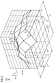
- FIG. 3 a diagram of a process variable evaluation of a second embodiment of the inventive method 100 is shown.
- the diagram comprises a first parameter axis 38, on which a first parameter 35 of a rigid transformation 30 with respect to a zero line 37 is plotted.
- the diagram also includes a second parameter axis 39 on which a second parameter 36 of the rigid transformation 30 is plotted relative to a zero line 37.
- the parameter axes 38, 39 span a plane in which the associated parameters 35, 36 are each modified within a variation width 47. The modification of the parameters 35, 36 takes place in separate step sizes 48, 49.
- An intersection point 45 of two values of the parameters 35, 36 in the plane spanned by the parameter axes 38, 39 corresponds to a rigid transformation 30, for the workpiece-fixed processing path 27 not shown in detail in the method 100 according to the invention taking into account the respective rigid transformation 30 is simulated.
- the process variable 40 is plotted along a process variable axis 44, which is determined by the associated simulation.
- the process variable axis 44 also has a zero line 37.
- a support point 42 corresponds to each of the intersection points 45 in the plane spanned by the parameter axes 38, 39.
- the plurality of interpolation points 42 define a segmented result surface 41, by means of which the rigid transformation 30 in which the process variable 40 reaches the selectable target value 43. According to FIG. 3 the selected target value 43 is a maximum of the process variable 40.
- FIG. 4 1 schematically shows a diagram of a third embodiment of the method 100 according to the invention.
- the diagram comprises a first parameter axis 38, on which a first parameter 35 of a rigid transformation 30 relative to a zero line 37 is plotted.
- the diagram also includes a second parameter axis 39 on which a second parameter 36 of the rigid transformation 30 is plotted relative to a zero line 37.
- the parameter axes 38, 39 span a plane in which the associated parameters 35, 36 are each modified within a variation width 47. The modification of the parameters 35, 36 takes place in separate step sizes 48, 49.
- An intersection point 45 of two values of the parameters 35, 36 in the plane spanned by the parameter axes 38, 39 corresponds to a rigid transformation 30, for which in the invention Method 100, the workpiece-fixed processing path 27, not shown in detail, taking into account the respective rigid transformation 30 is simulated.
- the process variable 40 is plotted along a process variable axis 44, which is determined by the associated simulation.
- the process variable axis 44 also has a zero line 37.
- a support point 42 corresponds to each of the intersection points 45 in the plane spanned by the parameter axes 38, 39.
- the support points 43 serve as data for creating a least-square polynomial with which the continuous result area 31 is determined.
- the support points 42 can also lie outside of the result surface 41 with a tolerance 33 along the process variable axis 44.
- a desired maximum or minimum can also be determined in a simple manner in a region between the support points 43.
- FIG. 5 a flowchart 5 of a fourth embodiment of the method 100 according to the invention is shown.
- a workpiece-fixed machining path 27 of the workpiece not shown in more detail 20, which is to be machined.
- a selection step 120 in which a rigid transformation 30 of the positioning of the workpiece 20 is selected.
- the rigid transformation 30 describes in which position and orientation the workpiece 20 is clamped in the production machine 50, not shown in the machining.
- a simulation step 130 in which the workpiece-fixed machining path 27 is traversed in a simulation taking into account the rigid transformation 30 selected in the previous method step 120.
- the workpiece-fixed processing path 27 is traversed when the workpiece 20 is clamped in accordance with the rigid transformation 30.
- a subsequent evaluation step 140 at least one process variable 40 is determined, which results from the selected machining of the workpiece 20.
- the process variable 40 may be, for example, a ratio of operating times of drive means 54 on different machine axes 53 of the production machine 50.
- a test step 145 in which it is checked whether the at least process variable 40 determined in the preceding evaluation step 140 reaches a selected target value 43.
- the target value 43 is a maximum, a minimum, or a selectable value.
- the corresponding rigid transformation 30 is output to a user as a result of the inventive method 100 at the end of the process 150.
- a return 160 of the method 100 according to the invention to the selection step 120 and a new passage of the method 100 is carried out.
- a different rigid transformation 30 is selected in the selection step 120 than in the previous pass.
- the rigid transformation 30 is modified for the new passage by at least a parameter 35, 36 of the rigid transformation 30 is changed.
Landscapes
- Engineering & Computer Science (AREA)
- Human Computer Interaction (AREA)
- Manufacturing & Machinery (AREA)
- Physics & Mathematics (AREA)
- General Physics & Mathematics (AREA)
- Automation & Control Theory (AREA)
- Numerical Control (AREA)
Claims (11)
- Procédé (100) d'alignement d'une pièce (20) à usiner avec enlèvement de copeaux, comprenant les stades dans lesquels :a) on dispose d'un trajet (27) d'usinage fixe par rapport à la pièce pour usiner la pièce (20) ;b) on choisit une transformation (30) rigide du positionnement de la pièce (20) ;c) on simule le trajet (27) d'usinage fixe par rapport à la pièce en tenant compte de la transformation (30) rigide du positionnement de la pièce (20) ;d) on détermine au moins une grandeur (40) de processus de l'usinage avec enlèvement de copeaux de la pièce (20) ;caractérisé en ce que l'on répète les stades b) à d) en modifiant la au moins une transformation (30) rigide du positionnement de la pièce (20) jusqu'à ce que la au moins une grandeur (40) de processus atteigne une valeur (43) cible, la au moins une grandeur (40) de processus étant un rapport de durées de fonctionnement de, respectivement, un moyen (54) d'entraînement d'au moins deux axes (53) de machine, et la valeur (43) cible étant une valeur pouvant être choisie.
- Procédé (100) suivant la revendication 1, caractérisé en ce que la au moins une transformation (30) rigide comprend, comme paramètres (32, 34, 35, 36) un déplacement (32) en translation et/ou un angle (34) d'alignement de la pièce (20).
- Procédé (100) suivant la revendication 1 ou 2, caractérisé en ce que le rapport des durées de fonctionnement des moyens (54) d'entraînement des au moins deux axes (53) de machine est sensiblement égal à un.
- Procédé (100) suivant l'une des revendications 1 à 3, caractérisé en ce que l'on effectue, itérativement jusqu'à au moins trois fois, les stades a) à d) pour au moins un paramètre (32, 34, 35, 36) pouvant être choisi de la transformation (30) rigide.
- Procédé (100) suivant l'une des revendications 1 à 4, caractérisé en ce que la valeur (43) cible est le résultat d'une optimisation non linéaire, d'un procédé de Newton ou d'un optimum d'un polynôme des moindres carrés.
- Procédé (100) suivant la revendication 5, caractérisé en ce que les grandeurs (40) de processus déterminées au stade d) sont les points (43) de base de l'optimisation non linéaire du procédé de Newton ou du polynôme des moindres carrés.
- Procédé (100) suivant l'une des revendications 1 à 6, caractérisé en ce que, dans un premier passage, on modifie un premier paramètre (35) de la transformation (30) rigide et, si la valeur (43) cible n'est pas atteinte, dans un deuxième passage, on modifie un deuxième paramètre (36) de la transformation (30) rigide.
- Procédé (100) suivant l'une des revendications 2 à 5, caractérisé en ce que l'on effectue le stade c) en tenant compte d'au moins une condition aux limites de la machine (50) de production, notamment d'une longueur maximum de déplacement, d'une accélération maximum, d'une secousse maximum et/ou d'une vitesse de coupe maximum de l'outil (10) suivant le au moins un axe (53) de la machine.
- Programme (80) à effectuer dans une mémoire d'une unité (56) de commande d'une machine (50) de production, qui est constitué pour émettre des instructions de commande à des moyens (54) d'entraînement d'axes (53) de la machine, caractérisé en ce que le programme (80) est constitué pour effectuer au moins l'un des procédés (100) suivant les revendications 1 à 8.
- Unité (56) de commande pour commander au moins un moyen (54) d'entraînement d'une machine (50) de production, qui est constituée en ayant une mémoire et une unité de calcul pour la mise en mémoire et l'exécution d'un programme (80) suivant la revendication 9.
- Machine (50) de production comprenant un outil (10), qui peut être déplacée le long d'au moins deux axes (53) de la machine par, respectivement, au moins un moyen (54) d'entraînement, et une unité (56) de commande ayant une mémoire, qui est constituée pour mettre en mémoire et exécuter un programme (80) suivant la revendication 9.
Applications Claiming Priority (2)
| Application Number | Priority Date | Filing Date | Title |
|---|---|---|---|
| EP15178412.1A EP3125054A1 (fr) | 2015-07-27 | 2015-07-27 | Procede d'alignement pour pieces |
| PCT/EP2016/066380 WO2017016855A1 (fr) | 2015-07-27 | 2016-07-11 | Procédé d'orientation de pièces |
Publications (2)
| Publication Number | Publication Date |
|---|---|
| EP3300521A1 EP3300521A1 (fr) | 2018-04-04 |
| EP3300521B1 true EP3300521B1 (fr) | 2019-12-04 |
Family
ID=53724093
Family Applications (2)
| Application Number | Title | Priority Date | Filing Date |
|---|---|---|---|
| EP15178412.1A Withdrawn EP3125054A1 (fr) | 2015-07-27 | 2015-07-27 | Procede d'alignement pour pieces |
| EP16747740.5A Active EP3300521B1 (fr) | 2015-07-27 | 2016-07-11 | Procede d'alignement pour pieces |
Family Applications Before (1)
| Application Number | Title | Priority Date | Filing Date |
|---|---|---|---|
| EP15178412.1A Withdrawn EP3125054A1 (fr) | 2015-07-27 | 2015-07-27 | Procede d'alignement pour pieces |
Country Status (4)
| Country | Link |
|---|---|
| US (1) | US10466680B2 (fr) |
| EP (2) | EP3125054A1 (fr) |
| CN (1) | CN107850886B (fr) |
| WO (1) | WO2017016855A1 (fr) |
Families Citing this family (3)
| Publication number | Priority date | Publication date | Assignee | Title |
|---|---|---|---|---|
| JP6480896B2 (ja) * | 2016-07-28 | 2019-03-13 | ファナック株式会社 | 数値制御装置および工具の移動制御方法 |
| JP6423827B2 (ja) * | 2016-07-28 | 2018-11-14 | ファナック株式会社 | 数値制御装置および工具の移動制御方法 |
| EP3370127A1 (fr) | 2017-03-01 | 2018-09-05 | Siemens Aktiengesellschaft | Procédé de fonctionnement d'une machine-outil ou de production, machine-outil ou de production fonctionnant selon ledit procédé et programme informatique pour mettre en uvre le procédé |
Family Cites Families (13)
| Publication number | Priority date | Publication date | Assignee | Title |
|---|---|---|---|---|
| DE4305408A1 (de) * | 1993-02-22 | 1994-08-25 | Sumitomo Heavy Industries | Verfahren zum Vermessen von Zahnrädern sowie Anordnung zum spanenden Bearbeiten und Vermessen von Zahnrädern |
| AUPO206596A0 (en) * | 1996-08-30 | 1996-09-26 | Anca Pty Ltd | Tool grinding simulation system |
| GB0419381D0 (en) | 2004-09-01 | 2004-10-06 | Renishaw Plc | Machine tool method |
| ITTV20060184A1 (it) * | 2006-10-19 | 2008-04-20 | For El Base Di Vianello Fortunato & C Snc | Macchina automatica e procedimento automatico per la smerigliatura dei bordi di lastre di vetro. |
| DE102007016056B4 (de) * | 2007-04-03 | 2011-08-25 | Sauer GmbH LASERTEC, 87437 | Verfahren und Vorrichtung zur Werkstückeinmessung und Werkstückbearbeitung |
| DE102009008121A1 (de) * | 2009-02-09 | 2010-08-19 | Deckel Maho Pfronten Gmbh | Verfahren und Vorrichtung zum Erzeugen von transformierten Steuerdaten zum Steuern eines Werkzeugs an einer Werkzeugmaschine |
| KR101179071B1 (ko) * | 2009-03-10 | 2012-09-03 | 주식회사 엘지화학 | 사각형 단위체의 제조방법 |
| US8938314B2 (en) * | 2010-11-16 | 2015-01-20 | International Business Machines Corporation | Smart energy consumption management |
| DE102012201732B4 (de) * | 2012-02-06 | 2024-04-18 | Deckel Maho Pfronten Gmbh | Numerisch gesteuerte Werkzeugmaschine und Verfahren zum Steuern eines automatischen rotatorischen Ausrichtvorgangs eines Zahnrads an der Werkzeugmaschine |
| EP2796954B1 (fr) | 2013-04-23 | 2015-11-25 | Siemens Aktiengesellschaft | Commande numérique avec information d'un système CAM lors du changement du programme de pièces |
| EP2796952B1 (fr) | 2013-04-25 | 2016-01-20 | Siemens Aktiengesellschaft | Commande numérique avec possibilité de modification du programme des pièces |
| US9684297B2 (en) * | 2013-05-20 | 2017-06-20 | Robert Cecil, JR. | System and method for double rotation optimization |
| EP2952990B1 (fr) | 2014-06-06 | 2019-02-20 | Siemens Aktiengesellschaft | Commande optimisée d'une machine d'usinage pour enlèvement de copeaux |
-
2015
- 2015-07-27 EP EP15178412.1A patent/EP3125054A1/fr not_active Withdrawn
-
2016
- 2016-07-11 EP EP16747740.5A patent/EP3300521B1/fr active Active
- 2016-07-11 CN CN201680037577.7A patent/CN107850886B/zh active Active
- 2016-07-11 US US15/748,045 patent/US10466680B2/en active Active
- 2016-07-11 WO PCT/EP2016/066380 patent/WO2017016855A1/fr not_active Ceased
Non-Patent Citations (1)
| Title |
|---|
| None * |
Also Published As
| Publication number | Publication date |
|---|---|
| WO2017016855A1 (fr) | 2017-02-02 |
| US20180224828A1 (en) | 2018-08-09 |
| EP3125054A1 (fr) | 2017-02-01 |
| CN107850886A (zh) | 2018-03-27 |
| EP3300521A1 (fr) | 2018-04-04 |
| US10466680B2 (en) | 2019-11-05 |
| CN107850886B (zh) | 2019-05-07 |
Similar Documents
| Publication | Publication Date | Title |
|---|---|---|
| DE102015111964B4 (de) | Servomotoren-Steuersystem, das die Bearbeitungspräzision mehrerer Achsen verbessert | |
| DE102017207822A1 (de) | Vorrichtung zur verarbeitung eines bearbeitungsprogramms und damit ausgestattete mehrachsige bearbeitungsmaschine | |
| EP2952990B1 (fr) | Commande optimisée d'une machine d'usinage pour enlèvement de copeaux | |
| EP3115857A1 (fr) | Procédé de détermination de trajectoire pour mouvements de temps mort | |
| EP3115856A1 (fr) | Procédé de détermination de trajectoire pour mouvements de temps mort | |
| EP2861368A1 (fr) | Procédé pour générer une denture et machine à former les dentures fonctionnant au moyen de ce procédé | |
| WO2011110289A1 (fr) | Procédé de détermination d'un tracé de courbe nominale optimisé dans une machine à plusieurs axes pour le traitement volant de produit transporté | |
| DE102018004444B4 (de) | Steuervorrichtung mit Bewertungsprogramm und Parameteroptimierungsverfahren | |
| EP3125054A1 (fr) | Procede d'alignement pour pieces | |
| EP3317734B1 (fr) | Procédé de commande de mouvement d'un outil et dispositif de commande | |
| EP4137899A1 (fr) | Procédé de détermination d'une trajectoire d'usinage et procédé d'usinage d'une pièce au moyen d'une machine d'usinage à axes multiples | |
| EP3309635A1 (fr) | Détermination d'un programme de pièce optimisé pour une machine de traitement respective | |
| EP2623271B1 (fr) | Procédé destiné au fonctionnement d'une machine de traitement | |
| EP2994258B1 (fr) | Procédé de réalisation par enlèvement de copeaux d'évidement dans des pièces et dispositif associé | |
| WO2017045884A1 (fr) | Procédé de fourniture d'un profil de trajectoire, dispositif de commande, machine ainsi que programme d'ordinateur | |
| DE112022007248T5 (de) | Steuergerät und computerlesbares Aufzeichnungsmedium | |
| EP3125055A1 (fr) | Procede de guidage d'outil pour des surfaces adjacentes | |
| DE102011052314A1 (de) | Verfahren und Werkzeugmaschine zur Herstellung einer bogenförmigen Flanke an einem Werkstück | |
| EP3045272A1 (fr) | Commande d'une machine de traitement avec un premier nombre d'axes de machine réglables | |
| DE102015108535B3 (de) | Verfahren zur Werkzeugsubstitution | |
| DE102014004654A1 (de) | Verfahren zum Bestimmen einer Bearbeitungsreihenfolge für ein spanend zu bearbeitendes Werkstück | |
| DE102013021653A1 (de) | Verfahren zur Steuerung einer Bearbeitungsmaschine | |
| DE112022007246T5 (de) | Steuergerät und computerlesbares Aufzeichnungsmedium | |
| WO2018033404A1 (fr) | Génération de données de bande optimisées pour une machine-outil | |
| DE102014201277A1 (de) | Verfahren und Vorrichtung zur Bearbeitung von Werkstücken |
Legal Events
| Date | Code | Title | Description |
|---|---|---|---|
| STAA | Information on the status of an ep patent application or granted ep patent |
Free format text: STATUS: THE INTERNATIONAL PUBLICATION HAS BEEN MADE |
|
| PUAI | Public reference made under article 153(3) epc to a published international application that has entered the european phase |
Free format text: ORIGINAL CODE: 0009012 |
|
| STAA | Information on the status of an ep patent application or granted ep patent |
Free format text: STATUS: REQUEST FOR EXAMINATION WAS MADE |
|
| 17P | Request for examination filed |
Effective date: 20171227 |
|
| AK | Designated contracting states |
Kind code of ref document: A1 Designated state(s): AL AT BE BG CH CY CZ DE DK EE ES FI FR GB GR HR HU IE IS IT LI LT LU LV MC MK MT NL NO PL PT RO RS SE SI SK SM TR |
|
| AX | Request for extension of the european patent |
Extension state: BA ME |
|
| DAV | Request for validation of the european patent (deleted) | ||
| DAX | Request for extension of the european patent (deleted) | ||
| GRAP | Despatch of communication of intention to grant a patent |
Free format text: ORIGINAL CODE: EPIDOSNIGR1 |
|
| STAA | Information on the status of an ep patent application or granted ep patent |
Free format text: STATUS: GRANT OF PATENT IS INTENDED |
|
| INTG | Intention to grant announced |
Effective date: 20190731 |
|
| GRAS | Grant fee paid |
Free format text: ORIGINAL CODE: EPIDOSNIGR3 |
|
| GRAA | (expected) grant |
Free format text: ORIGINAL CODE: 0009210 |
|
| STAA | Information on the status of an ep patent application or granted ep patent |
Free format text: STATUS: THE PATENT HAS BEEN GRANTED |
|
| AK | Designated contracting states |
Kind code of ref document: B1 Designated state(s): AL AT BE BG CH CY CZ DE DK EE ES FI FR GB GR HR HU IE IS IT LI LT LU LV MC MK MT NL NO PL PT RO RS SE SI SK SM TR |
|
| REG | Reference to a national code |
Ref country code: GB Ref legal event code: FG4D Free format text: NOT ENGLISH |
|
| REG | Reference to a national code |
Ref country code: CH Ref legal event code: EP |
|
| REG | Reference to a national code |
Ref country code: AT Ref legal event code: REF Ref document number: 1210152 Country of ref document: AT Kind code of ref document: T Effective date: 20191215 |
|
| REG | Reference to a national code |
Ref country code: DE Ref legal event code: R096 Ref document number: 502016007883 Country of ref document: DE |
|
| REG | Reference to a national code |
Ref country code: IE Ref legal event code: FG4D Free format text: LANGUAGE OF EP DOCUMENT: GERMAN |
|
| REG | Reference to a national code |
Ref country code: NL Ref legal event code: MP Effective date: 20191204 |
|
| REG | Reference to a national code |
Ref country code: LT Ref legal event code: MG4D |
|
| PG25 | Lapsed in a contracting state [announced via postgrant information from national office to epo] |
Ref country code: BG Free format text: LAPSE BECAUSE OF FAILURE TO SUBMIT A TRANSLATION OF THE DESCRIPTION OR TO PAY THE FEE WITHIN THE PRESCRIBED TIME-LIMIT Effective date: 20200304 Ref country code: FI Free format text: LAPSE BECAUSE OF FAILURE TO SUBMIT A TRANSLATION OF THE DESCRIPTION OR TO PAY THE FEE WITHIN THE PRESCRIBED TIME-LIMIT Effective date: 20191204 Ref country code: LT Free format text: LAPSE BECAUSE OF FAILURE TO SUBMIT A TRANSLATION OF THE DESCRIPTION OR TO PAY THE FEE WITHIN THE PRESCRIBED TIME-LIMIT Effective date: 20191204 Ref country code: NO Free format text: LAPSE BECAUSE OF FAILURE TO SUBMIT A TRANSLATION OF THE DESCRIPTION OR TO PAY THE FEE WITHIN THE PRESCRIBED TIME-LIMIT Effective date: 20200304 Ref country code: GR Free format text: LAPSE BECAUSE OF FAILURE TO SUBMIT A TRANSLATION OF THE DESCRIPTION OR TO PAY THE FEE WITHIN THE PRESCRIBED TIME-LIMIT Effective date: 20200305 Ref country code: SE Free format text: LAPSE BECAUSE OF FAILURE TO SUBMIT A TRANSLATION OF THE DESCRIPTION OR TO PAY THE FEE WITHIN THE PRESCRIBED TIME-LIMIT Effective date: 20191204 Ref country code: LV Free format text: LAPSE BECAUSE OF FAILURE TO SUBMIT A TRANSLATION OF THE DESCRIPTION OR TO PAY THE FEE WITHIN THE PRESCRIBED TIME-LIMIT Effective date: 20191204 |
|
| PG25 | Lapsed in a contracting state [announced via postgrant information from national office to epo] |
Ref country code: RS Free format text: LAPSE BECAUSE OF FAILURE TO SUBMIT A TRANSLATION OF THE DESCRIPTION OR TO PAY THE FEE WITHIN THE PRESCRIBED TIME-LIMIT Effective date: 20191204 Ref country code: HR Free format text: LAPSE BECAUSE OF FAILURE TO SUBMIT A TRANSLATION OF THE DESCRIPTION OR TO PAY THE FEE WITHIN THE PRESCRIBED TIME-LIMIT Effective date: 20191204 |
|
| PG25 | Lapsed in a contracting state [announced via postgrant information from national office to epo] |
Ref country code: AL Free format text: LAPSE BECAUSE OF FAILURE TO SUBMIT A TRANSLATION OF THE DESCRIPTION OR TO PAY THE FEE WITHIN THE PRESCRIBED TIME-LIMIT Effective date: 20191204 |
|
| PG25 | Lapsed in a contracting state [announced via postgrant information from national office to epo] |
Ref country code: EE Free format text: LAPSE BECAUSE OF FAILURE TO SUBMIT A TRANSLATION OF THE DESCRIPTION OR TO PAY THE FEE WITHIN THE PRESCRIBED TIME-LIMIT Effective date: 20191204 Ref country code: PT Free format text: LAPSE BECAUSE OF FAILURE TO SUBMIT A TRANSLATION OF THE DESCRIPTION OR TO PAY THE FEE WITHIN THE PRESCRIBED TIME-LIMIT Effective date: 20200429 Ref country code: RO Free format text: LAPSE BECAUSE OF FAILURE TO SUBMIT A TRANSLATION OF THE DESCRIPTION OR TO PAY THE FEE WITHIN THE PRESCRIBED TIME-LIMIT Effective date: 20191204 Ref country code: NL Free format text: LAPSE BECAUSE OF FAILURE TO SUBMIT A TRANSLATION OF THE DESCRIPTION OR TO PAY THE FEE WITHIN THE PRESCRIBED TIME-LIMIT Effective date: 20191204 Ref country code: CZ Free format text: LAPSE BECAUSE OF FAILURE TO SUBMIT A TRANSLATION OF THE DESCRIPTION OR TO PAY THE FEE WITHIN THE PRESCRIBED TIME-LIMIT Effective date: 20191204 Ref country code: ES Free format text: LAPSE BECAUSE OF FAILURE TO SUBMIT A TRANSLATION OF THE DESCRIPTION OR TO PAY THE FEE WITHIN THE PRESCRIBED TIME-LIMIT Effective date: 20191204 |
|
| PG25 | Lapsed in a contracting state [announced via postgrant information from national office to epo] |
Ref country code: SK Free format text: LAPSE BECAUSE OF FAILURE TO SUBMIT A TRANSLATION OF THE DESCRIPTION OR TO PAY THE FEE WITHIN THE PRESCRIBED TIME-LIMIT Effective date: 20191204 Ref country code: SM Free format text: LAPSE BECAUSE OF FAILURE TO SUBMIT A TRANSLATION OF THE DESCRIPTION OR TO PAY THE FEE WITHIN THE PRESCRIBED TIME-LIMIT Effective date: 20191204 Ref country code: IS Free format text: LAPSE BECAUSE OF FAILURE TO SUBMIT A TRANSLATION OF THE DESCRIPTION OR TO PAY THE FEE WITHIN THE PRESCRIBED TIME-LIMIT Effective date: 20200404 |
|
| REG | Reference to a national code |
Ref country code: DE Ref legal event code: R097 Ref document number: 502016007883 Country of ref document: DE |
|
| PLBE | No opposition filed within time limit |
Free format text: ORIGINAL CODE: 0009261 |
|
| STAA | Information on the status of an ep patent application or granted ep patent |
Free format text: STATUS: NO OPPOSITION FILED WITHIN TIME LIMIT |
|
| PG25 | Lapsed in a contracting state [announced via postgrant information from national office to epo] |
Ref country code: DK Free format text: LAPSE BECAUSE OF FAILURE TO SUBMIT A TRANSLATION OF THE DESCRIPTION OR TO PAY THE FEE WITHIN THE PRESCRIBED TIME-LIMIT Effective date: 20191204 |
|
| 26N | No opposition filed |
Effective date: 20200907 |
|
| PG25 | Lapsed in a contracting state [announced via postgrant information from national office to epo] |
Ref country code: PL Free format text: LAPSE BECAUSE OF FAILURE TO SUBMIT A TRANSLATION OF THE DESCRIPTION OR TO PAY THE FEE WITHIN THE PRESCRIBED TIME-LIMIT Effective date: 20191204 Ref country code: SI Free format text: LAPSE BECAUSE OF FAILURE TO SUBMIT A TRANSLATION OF THE DESCRIPTION OR TO PAY THE FEE WITHIN THE PRESCRIBED TIME-LIMIT Effective date: 20191204 |
|
| PG25 | Lapsed in a contracting state [announced via postgrant information from national office to epo] |
Ref country code: MC Free format text: LAPSE BECAUSE OF FAILURE TO SUBMIT A TRANSLATION OF THE DESCRIPTION OR TO PAY THE FEE WITHIN THE PRESCRIBED TIME-LIMIT Effective date: 20191204 |
|
| REG | Reference to a national code |
Ref country code: CH Ref legal event code: PL |
|
| GBPC | Gb: european patent ceased through non-payment of renewal fee |
Effective date: 20200711 |
|
| REG | Reference to a national code |
Ref country code: BE Ref legal event code: MM Effective date: 20200731 |
|
| PG25 | Lapsed in a contracting state [announced via postgrant information from national office to epo] |
Ref country code: LI Free format text: LAPSE BECAUSE OF NON-PAYMENT OF DUE FEES Effective date: 20200731 Ref country code: LU Free format text: LAPSE BECAUSE OF NON-PAYMENT OF DUE FEES Effective date: 20200711 Ref country code: CH Free format text: LAPSE BECAUSE OF NON-PAYMENT OF DUE FEES Effective date: 20200731 Ref country code: GB Free format text: LAPSE BECAUSE OF NON-PAYMENT OF DUE FEES Effective date: 20200711 |
|
| PG25 | Lapsed in a contracting state [announced via postgrant information from national office to epo] |
Ref country code: BE Free format text: LAPSE BECAUSE OF NON-PAYMENT OF DUE FEES Effective date: 20200731 |
|
| PG25 | Lapsed in a contracting state [announced via postgrant information from national office to epo] |
Ref country code: IE Free format text: LAPSE BECAUSE OF NON-PAYMENT OF DUE FEES Effective date: 20200711 |
|
| PG25 | Lapsed in a contracting state [announced via postgrant information from national office to epo] |
Ref country code: TR Free format text: LAPSE BECAUSE OF FAILURE TO SUBMIT A TRANSLATION OF THE DESCRIPTION OR TO PAY THE FEE WITHIN THE PRESCRIBED TIME-LIMIT Effective date: 20191204 Ref country code: MT Free format text: LAPSE BECAUSE OF FAILURE TO SUBMIT A TRANSLATION OF THE DESCRIPTION OR TO PAY THE FEE WITHIN THE PRESCRIBED TIME-LIMIT Effective date: 20191204 Ref country code: CY Free format text: LAPSE BECAUSE OF FAILURE TO SUBMIT A TRANSLATION OF THE DESCRIPTION OR TO PAY THE FEE WITHIN THE PRESCRIBED TIME-LIMIT Effective date: 20191204 |
|
| PG25 | Lapsed in a contracting state [announced via postgrant information from national office to epo] |
Ref country code: MK Free format text: LAPSE BECAUSE OF FAILURE TO SUBMIT A TRANSLATION OF THE DESCRIPTION OR TO PAY THE FEE WITHIN THE PRESCRIBED TIME-LIMIT Effective date: 20191204 |
|
| REG | Reference to a national code |
Ref country code: AT Ref legal event code: MM01 Ref document number: 1210152 Country of ref document: AT Kind code of ref document: T Effective date: 20210711 |
|
| PG25 | Lapsed in a contracting state [announced via postgrant information from national office to epo] |
Ref country code: AT Free format text: LAPSE BECAUSE OF NON-PAYMENT OF DUE FEES Effective date: 20210711 |
|
| PGFP | Annual fee paid to national office [announced via postgrant information from national office to epo] |
Ref country code: DE Payment date: 20250919 Year of fee payment: 10 |
|
| PGFP | Annual fee paid to national office [announced via postgrant information from national office to epo] |
Ref country code: IT Payment date: 20250718 Year of fee payment: 10 |
|
| PGFP | Annual fee paid to national office [announced via postgrant information from national office to epo] |
Ref country code: FR Payment date: 20250716 Year of fee payment: 10 |