EP2515726B1 - Unité d'infusion pour boissons pourvue d'un système de fermeture hydraulique - Google Patents
Unité d'infusion pour boissons pourvue d'un système de fermeture hydraulique Download PDFInfo
- Publication number
- EP2515726B1 EP2515726B1 EP10810927.3A EP10810927A EP2515726B1 EP 2515726 B1 EP2515726 B1 EP 2515726B1 EP 10810927 A EP10810927 A EP 10810927A EP 2515726 B1 EP2515726 B1 EP 2515726B1
- Authority
- EP
- European Patent Office
- Prior art keywords
- piston
- hot water
- infusion
- cylinder
- chamber
- Prior art date
- Legal status (The legal status is an assumption and is not a legal conclusion. Google has not performed a legal analysis and makes no representation as to the accuracy of the status listed.)
- Active
Links
Images





Classifications
-
- A—HUMAN NECESSITIES
- A47—FURNITURE; DOMESTIC ARTICLES OR APPLIANCES; COFFEE MILLS; SPICE MILLS; SUCTION CLEANERS IN GENERAL
- A47J—KITCHEN EQUIPMENT; COFFEE MILLS; SPICE MILLS; APPARATUS FOR MAKING BEVERAGES
- A47J31/00—Apparatus for making beverages
- A47J31/24—Coffee-making apparatus in which hot water is passed through the filter under pressure, i.e. in which the coffee grounds are extracted under pressure
- A47J31/34—Coffee-making apparatus in which hot water is passed through the filter under pressure, i.e. in which the coffee grounds are extracted under pressure with hot water under liquid pressure
- A47J31/36—Coffee-making apparatus in which hot water is passed through the filter under pressure, i.e. in which the coffee grounds are extracted under pressure with hot water under liquid pressure with mechanical pressure-producing means
- A47J31/3604—Coffee-making apparatus in which hot water is passed through the filter under pressure, i.e. in which the coffee grounds are extracted under pressure with hot water under liquid pressure with mechanical pressure-producing means with a mechanism arranged to move the brewing chamber between loading, infusing and ejecting stations
- A47J31/3623—Cartridges being employed
- A47J31/3633—Means to perform transfer from a loading position to an infusing position
-
- A—HUMAN NECESSITIES
- A47—FURNITURE; DOMESTIC ARTICLES OR APPLIANCES; COFFEE MILLS; SPICE MILLS; SUCTION CLEANERS IN GENERAL
- A47J—KITCHEN EQUIPMENT; COFFEE MILLS; SPICE MILLS; APPARATUS FOR MAKING BEVERAGES
- A47J31/00—Apparatus for making beverages
- A47J31/24—Coffee-making apparatus in which hot water is passed through the filter under pressure, i.e. in which the coffee grounds are extracted under pressure
- A47J31/34—Coffee-making apparatus in which hot water is passed through the filter under pressure, i.e. in which the coffee grounds are extracted under pressure with hot water under liquid pressure
- A47J31/36—Coffee-making apparatus in which hot water is passed through the filter under pressure, i.e. in which the coffee grounds are extracted under pressure with hot water under liquid pressure with mechanical pressure-producing means
-
- A—HUMAN NECESSITIES
- A47—FURNITURE; DOMESTIC ARTICLES OR APPLIANCES; COFFEE MILLS; SPICE MILLS; SUCTION CLEANERS IN GENERAL
- A47J—KITCHEN EQUIPMENT; COFFEE MILLS; SPICE MILLS; APPARATUS FOR MAKING BEVERAGES
- A47J31/00—Apparatus for making beverages
- A47J31/24—Coffee-making apparatus in which hot water is passed through the filter under pressure, i.e. in which the coffee grounds are extracted under pressure
- A47J31/34—Coffee-making apparatus in which hot water is passed through the filter under pressure, i.e. in which the coffee grounds are extracted under pressure with hot water under liquid pressure
- A47J31/36—Coffee-making apparatus in which hot water is passed through the filter under pressure, i.e. in which the coffee grounds are extracted under pressure with hot water under liquid pressure with mechanical pressure-producing means
- A47J31/3666—Coffee-making apparatus in which hot water is passed through the filter under pressure, i.e. in which the coffee grounds are extracted under pressure with hot water under liquid pressure with mechanical pressure-producing means whereby the loading of the brewing chamber with the brewing material is performed by the user
- A47J31/3676—Cartridges being employed
- A47J31/368—Permeable cartridges being employed
- A47J31/3685—Brewing heads therefor
-
- A—HUMAN NECESSITIES
- A47—FURNITURE; DOMESTIC ARTICLES OR APPLIANCES; COFFEE MILLS; SPICE MILLS; SUCTION CLEANERS IN GENERAL
- A47J—KITCHEN EQUIPMENT; COFFEE MILLS; SPICE MILLS; APPARATUS FOR MAKING BEVERAGES
- A47J31/00—Apparatus for making beverages
- A47J31/44—Parts or details or accessories of beverage-making apparatus
- A47J31/4403—Constructional details
- A47J31/446—Filter holding means; Attachment of filters to beverage-making apparatus
- A47J31/4467—Filter holding means; Attachment of filters to beverage-making apparatus by means of linear guides, e.g. drawer-type engagement
Definitions
- the present invention relates to improvements to machines for making beverages, in particular but not exclusively for making espresso coffee, and to the infusion units built in said machines.
- machines for making beverages in particular for machines for making coffee such as espresso coffee or the like, of the automatic or semi-automatic type, for household or professional use, which use single-dose coffee capsules or other ingredients for making beverages, or loose products that are first inserted into a filter or cup that is then placed into an infusion unit.
- machines for making coffee such as espresso coffee or the like
- automatic or semi-automatic type for household or professional use, which use single-dose coffee capsules or other ingredients for making beverages, or loose products that are first inserted into a filter or cup that is then placed into an infusion unit.
- WO-A-2009/069167 describes an infusion unit for making coffee, comprising a sliding drawer, forming a moving element with a seat for single-dose capsules containing coffee powder or other ingredients for making a beverage, in particular espresso coffee.
- the moving element can shift from a loading position of the capsules to an infusion position, wherein the capsule seat is interposed between a hot water dispensing device and a beverage outlet nozzle, opposite to each other.
- Some coffee machines in particular in machines using infusion capsules containing coffee powders, which are inserted in a drawer system of the type described above, exhibit a system for closing the infusion chamber of the hydraulic type.
- An example of this infusion unit with hydraulic closure of the infusion chamber is described in WO2009/093202 .
- the piston also comprises a water heating system and is removably constrained to a stem stiffly connected to a hydraulic piston sliding in a hydraulic cylinder forming a cylinder/piston actuator with the above hydraulic piston.
- This system is particularly complex and expensive to manufacture.
- WO-A-00/49926 discloses an infusion unit for making drinks, comprising a moving element with a seat for single-dose pods for the preparation of drinks, partly forming an infusion chamber and movable from a pod-charging position to an infusion position. In the infusion position the seat is placed between a hot water dispensing device and a beverage outlet nozzle opposite one another.
- the water dispensing device includes an instant boiler with an axial duct connecting the instant boiler to an upper movable portion of the infusion chamber.
- the upper movable portion of the infusion chamber forms the bottom of a movable cylinder of a piston-cylinder actuator which controls closing and opening of the brewing chamber.
- Cold water is fed in an annular chamber formed by said axial duct connecting the instant boiler to the brewing chamber, by an outer cylindrical wall and by a bottom wall integral with said cylindrical wall and forming said upper portion of the brewing chamber.
- This known device is complex and expensive.
- the annular chamber of the piston-cylinder actuator is adjacent the brewing chamber, the cold water used to actuate the closure of the brewing chamber removes heat from the brewing water, which is detrimental as far as the quality of the brewed beverage is concerned.
- the invention aims at totally or partly overcoming one or more of the drawbacks of the prior art.
- the invention provides for an infusion unit according to independent claim 1.
- the infusion unit is made for handling single-dose capsules, for example made of a plastic material or the like, which contain coffee powder or other ingredients for making the beverage.
- the concepts at the basis of the invention may advantageously be used also in machines and infusion units wherein the ingredients are inserted into the machine in a different manner, for example placing them into a cup or filter, that is, in a containment member provided with a pierced wall that allows the outflow of the beverage or other food product obtained by extracting the flavours from the ingredients with hot water under pressure.
- the moving element for managing the capsules or other containers of ingredients for making the beverages may move between two positions only rather than three different positions, as described hereinafter with reference to the embodiment shown in the drawings.
- the invention also relates to a coffee machine comprising an infusion unit of the type defined above.
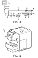
- Fig. 12 globally indicates a coffee machine 1, wherein an infusion unit according to the invention is built in, as shall be better described hereinafter in Figs. 1 to 10 .
- Machine 1 comprises, in a per se known manner, a water tank, a pump for feeding the water to a boiler, wherefrom the hot water under pressure is fed to the infusion unit, described hereinafter.
- the water fed by the pump is also used for closing the infusion unit, as shall be better described hereinafter.
- the infusion unit globally indicated with 3, comprises a bearing structure 5 defining side guides 7 for the sliding (according to the double arrow f9) of a moving element or unit globally indicated with 9.
- the moving element 9 is substantially configured as a drawer sliding along guides 7 and substantially exhibits a frame with a substantially rectangular development 11 with a wide window or central opening 13 that extends longitudinally in the direction of arrow f9.
- the trajectory performed by the moving element 9 is inclined relative to the horizontal for the purposes that shall be explained hereinafter.
- the moving element 9 carries a seat 15 for receiving single-dose capsules C of coffee powder for making espresso coffee or similar beverages.
- seat 15 is delimited on the one side by a wall 15A, with a substantially semicylindrical development, and on the opposite side by a pair of oscillating arms 15B hinged in 17 to the moving element 9.
- the inside surfaces of the oscillating arms 15B and the inside surface of wall 15A laterally delimit an infusion chamber whose shape corresponds to the shape of the single-dose capsule C.
- the infusion chamber is completed and closed at the top and at the bottom by mechanical components described hereinafter, so as to define a closed volume wherethrough hot water under pressure is made to flow to extract the flavours contained in the single-dose capsule C.
- the moving element 9 is fixed to a washing member globally indicated with 19.
- the washing member 19 exhibits a substantially cylindrical body 21 having a top face 21A and a bottom face 21B.
- an annular seat is made on the top face 21A for a seal 23A, whereas an annular seat is made on the bottom face for a bottom seal 23B, for the purposes described hereinafter.
- a conduit 25 develops through the substantially cylindrical body 21 of the washing member 19 that crosses the entire body 21 and is open on the top face 21 A and on the bottom face 2 1 B and more exactly at respective lowered zones made on said two top 21 A and bottom 21B faces.
- Body 21 of the washing member 19 is steadily constrained to the moving member 9 to move therewith.
- the constraint between body 21 of the washing member 19 and the moving member 9 comprises an elastic element, for example an elastic sheet 27.
- this elastic sheet 27 is formed integrally, with body 21 and with the moving element 9 or more exactly with frame 11 that is the main part thereof. This allows making the device with a simple plastic moulding operation.
- the elastic sheet 27 acts as laminar spring and allows a movement of body 21 of the washing member 19 in a direction substantially orthogonal to direction f9 of movement of the moving member 9 for the purposes described hereinafter.
- structure 5 exhibits a discharge opening 31 with a discharge hopper 33 developing downwards to discharge the spent capsules C.
- a collecting container may be positioned underneath the discharge opening 31. Adjacent the discharge opening 31 structure 5 carries an outlet nozzle of the beverage, globally indicated with 35. The nozzle may be fitted with two side spouts that allow dispensing the coffee or other beverage in one or two cups located one adjacent the other on a plane 1A ( Fig. 12 ) machine 1 is provided with.
- nozzle 35 for the beverage outlet is fitted with an outlet opening 37, preferably closed by a counter pressure valve 39 comprising for example a gate and an elastic member, in the example shown formed by a compression spring.
- the counter pressure valve 39 opens when the pressure of the infusion water in capsule C has reached a certain value, the valve being calibrated for obtaining particular organoleptic features of the drink.
- Structure 5 carries, in a position overlying and opposite the outlet nozzle 35 of the beverage, a hot water dispensing device 41.
- the dispensing device 41 exhibits a hydraulic closing system of the infusion chamber, as shown in the drawing.
- the hot water dispensing device may be made in a different way and have for example a mechanical closing system.
- the hot water dispensing device has no piercer, as it uses capsules C that need not be pierced.
- the hot water dispensing device 41 may be provided with a top piercer to pierce capsules C at the top. In the example shown there is provided a bottom piercer to pierce the bottom surface in capsules C.
- the hot water dispensing device 41 comprises a cylinder-piston actuator the cylinder whereof consists at least partly of a liner 43 seated in a seat 45 and locked therein by a closing flange 46.
- Liner 43 has a top closing wall 43A wherein a port 43B for feeding water under pressure opens.
- Port 43B is in connection with a chamber 43C wherein a first conduit 48 leads that feeds water under pressure fed by a pump, as shall be described hereinafter with reference to the schematic representation of the hydraulic circuit Fig. 11 .
- a piston 47 slides fitted with an annular seal 49 and at the top forming a pressure surface 47A.
- a pressure chamber with a variable volume is formed between pressure surface 47A and the inner surface of the top closing wall 43A of liner 43.
- Piston 47 also forms a collar 47B, surrounding a main body 47C of piston 47.
- the elastic members are formed by compression springs 51 arranged about the axis of piston 47 in a suitable number, for example three or four. Springs 51 are compressed between collar 47B of piston 47 and flange 46 constrained to seat 45. Cold pressurised water fed in the chamber between pressure surface 47A and closing wall 43A of liner 43 will cause a downward movement of the piston 47 against the force of the springs 51 which will be compressed as the volume of said chamber increases.
- body 47C of piston 47 is constrained to a block 53 forming a chamber 55 for feeding hot water under pressure.
- Chamber 55 is in connection with a conduit 57 for feeding hot water under pressure coming from the boiler machine 1 is fitted with and that shall be described briefly with reference to Fig. 11 .
- the hot water reaches a dispensing opening 53B ( Fig. 13 ) made on a bottom surface 53A of block 53, which forms a closing surface of the infusion chamber.
- Surfaces 53A and 47A are formed on opposed sides of the piston 47, including the piston body 47A and the block 53.
- the cold water flowing through conduit 48 and through port 43B into the pressure chamber of the cylinder-piston system 43, 47 is kept at a distance from the surface 53A which is in contact with the capsule C during the brewing chamber and which is in turn heated by the hot water flowing through duct 57 into chamber 55.
- chamber 55 for feeding the hot water and the dispensing opening 53B made on surface 53A of block 53 are in flow communication through a port 55A ( Fig. 13 ) that is closed by a calibrated valve 61 mounted on the piston 47.
- the calibrated valve 61 comprises a gate 63 elastically stressed by an elastic member, for example a helical compression spring 65 seated, along with gate 63, within a sliding seat formed in body 47C of piston 47.
- This calibrated valve 63 allows the proper operation of the hot water dispensing device 41 as shall be better clarified hereinafter with reference to the dispensing cycle.
- a channel 56 extends between opening 53B and port 55A visible in the section of Fig. 13 , wherethrough the hot water under pressure flows when it has reached an opening pressure of the calibrated valve 61.
- the block formed by flange 46 and by seat 45 is fixed relative to structure 5 and an elastic element 67 is constrained thereto, for example formed by a shaped elastic sheet having the function of ejecting capsule C from seat 15, as shall be described hereinafter with reference to the infusion cycle.
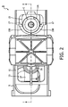
- Fig. 1 shows the position that the infusion unit takes when a new capsule C is charged into seat 15.
- the moving element or sliding drawer 9 is in a charging position, so as to be accessible to the user from outside machine 1. In this way it is easy to insert capsule C into the seat formed between the oscillating arms 15B and the fixed wall 15A constrained to the moving element 9.
- the moving element or drawer 9 is pushed within the machine up to moving seat 15 in alignment with the hot water dispensing device 41 and with the beverage outlet nozzle 35.
- capsule C is arranged with its bottom in contact with a disc 69 defining the bottom wall of the infusion chamber, the side walls thereof being formed by arms 15B and by wall 15A.
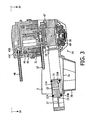
- capsule C has been brought to its infusion position ( Fig. 3 ) going beyond the elastic element 67 which in rest condition, is at a lower height than the top flange CF of capsule C in infusion position. This is made possible by the elasticity of the elastic element 67 and by the chamfered shape thereof that allows, under the effect of the thrust given by the moving element 9, the lifting of the elastic movement 67 and the overtaking of the latter by capsule C.
- the hot water dispensing device 41 is actuated feeding water under pressure in the cylinder formed by liner 43.
- the compression pushes wall 47A of piston 47 downwards causing the compression of springs 51 and thus the lowering of surface 53A against the top surface of capsule C in this way defining the top closing wall of the infusion chamber.
- the latter therefore remains formed by the bottom closing wall or surface 53A constrained to piston 47, by arms 15B, by wall 15A and by the wall formed by disc 69 associated to the drink outlet nozzle 35.
- the hot water under pressure fed through conduit 57 acts on the calibrated valve 61 to cause the opening thereof through the compression of spring 65 and upwards sliding of the cursor or gate 63, so as to put the hot water dispensing opening 53B in communication with the hot water feeding chamber 55.
- Valve 61 is calibrated so that the opening pressure is sufficiently high to ensure an adequate brewing pressure in capsule C, but sufficiently limited to ensure an adequate seal between the closing surface 53A and the top face or surface of capsule C.
- the hot water under pressure fed to chamber 55 and the water under pressure fed to the cylinder-piston actuator 43, 47 is provided by the same pump and therefore it has about the same pressure value in the two chambers.
- valve 61 It is therefore necessary to calibrate valve 61 considering the pressure at which the flavour extraction from the ingredients contained in capsule C must be carried out, the value of the closing force to be exerted on capsule C by the cylinder-piston actuator and the area of surfaces 47A and 53A.
- a check valve on water duct which feeds the boiler will keep the water pressure in the hot water conduit 57 lower than the water pressure in the cold water conduit 48, as will be described later on, such that upon opening of valve 61 a pressure difference still exists between the cold and hot water ducts respectively, said pressure difference, in combination with the surface on which the pressure is applied, ensures proper closure of the brewing chamber under sufficient brewing pressure in the capsule.
- the infusion unit is shown in the position immediately before the activation of the dispensing device 41, with the infusion chamber closing surface 53A still at a certain distance relative to the top surface of capsule C. It should be understood that the infusion occurs when piston 47 has lowered up to bringing surface 53A to press against the top surface of capsule C.
- piston 47 At the end of the drink dispensing, piston 47 is returned to the rest position by the effect of springs 51 and discharging the pressure into the circuit that feeds conduit 48 and conduit 57, so that also valve 61 closes.
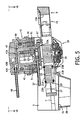
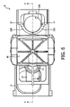
- the moving element or drawer 9 is again moved to the loading position of a new capsule, as shown in Figs. 5 and 6 .
- the elastic element 67 retains the spent capsule C, that is, just used in the infusion cycle that has just ended, in the infusion position, interposed between the hot water dispensing device 41 and the drink outlet nozzle 35.
- This empty capsule is discharged at the next infusion cycle, or with a loadless inwards movement of the moving element 9, as shown in Figs. 7 and 8 .
- arms 15B push the spent capsule C away from its infusion position bringing it towards the discharge opening 31.
- the inclination of the path (arrow f9) of the moving element 9 favours the discharge of the spent capsule and also the optional outflow towards discharge opening 31 of liquid that optionally remains in the infusion zone.
- the opening and closing movement of the elastic arms 15B for allowing the outlet of the empty capsule C and the subsequent ejection by thrust may be obtained by known systems, for example of the type described in WO-A-2009/069167 .
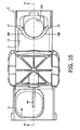
- the moving element 9 is brought to the position shown in Figs. 9 and 10 . With an extra-stroke outwards, the moving element 9 reaches such position that the washing member 19 is interposed between the drink outlet nozzle 35 and the hot water dispensing device 41, moving to the position normally taken by a capsule C.
- the hot water dispensing device 41 closes pushing piston 47 downwards until the bottom surface "53A of block 53 integral to piston 47 presses against the top face or surface 21A of body 21 of the washing member 19. The latter is pushed downwards with a bending of sheet 27 up to press the annular seal 23B against plate 69 surrounding the outlet port 37 of the beverage outlet nozzle 35. A sealed passage is thus formed that extends from the water dispensing opening 53B made on surface 53A up to port 37 and hence through the drink outlet nozzle 35, up to the drink dispensing spouts (not shown). By feeding hot water under pressure through conduit 57 it is so possible to wash the entire circuit downstream of surface 53A, removing any residues or deposits formed during the previous dispensing cycles.
- the movement of the moving element 9 can be obtained in any way. According to some embodiments, the movement is controlled manually for example by thrust, with a lever actuated by the user, or through an actuator, for example a hydraulic, pneumatic, electrical or similar actuator. In some embodiments it is possible to provide a pinion and rack mechanism, with a rack constrained to frame 11 of the moving element 9 and a pinion actuated by an electrical motor, not shown.
- the moving element 9 may be associated to microswitches for detecting its position during the various steps of the infusion or washing cycle, for providing the consensus to the dispensing of hot water under pressure.
- Fig. 11 schematically shows some components of the hydraulic circuit of machine 1.
- This figure shows a water tank 71 with an outlet conduit 73, whereon a feeding pump 75 is placed.
- Pump 75 feeds at an adequate pressure, for example between 8 and 12 bar, typically and preferably between 10 and 15 bar, the water collected from tank 71 towards the feeding conduit 77.
- the latter branches into a conduit 79 connected to conduit 48 described above for feeding the water under pressure provided by the pump 75 to the cylinder-piston actuator 43, 47.
- Reference numeral 81 indicates a second branching of conduit 77 that feeds a boiler 83.
- Boiler 83 may advantageously be an instant boiler, or a storage boiler.
- conduit 81 there is arranged a check valve 85 and a discharge valve 87 for discharging the pressure from the circuit at the end of the infusion cycle.
- a check valve 85 and a discharge valve 87 for discharging the pressure from the circuit at the end of the infusion cycle.
- the hot water under pressure is fed to a conduit 89 connected to conduit 57 described above, for feeding the hot water to chamber 55.
- a single pump 75 feeds water under pressure to both the closing actuator 43 and 47 of the infusion unit, and to the boiler that provides the water at the adequate pressure and temperature to the feeding chamber 55.
- the pressure in the circuit between pump 75 and the infusion unit 41 is discharged by opening valve 87.
- the check valve 85 prevents the outflow of water from boiler 83 towards the discharge and the calibrated valve 61 prevents the outflow of water towards the infusion zone.
- the arrangement of the calibrated valve 61 into the infusion unit prevents the need of a further check valve downstream of the boiler.
- the check valve 85 can be calibrated such that the water supplied by the pump 75 is fed at a first, higher pressure to the cold water conduit 48 and at a second, lower pressure to the boiler 83 and to the infusion chamber.
- valve 85 can be calibrated to maintain a 2 Bar pressure difference between the cold water conduit 48 and the hot water conduit 57.
- the calibrated valve 61 is designed such that it opens at a pre-set pressure value and causes only a negligible loss of pressure in the water flowing there through.
- Gate 63 is slidingly housed in a sliding seat 62 and is provided with a front stem 63A sealingly engaging aperture 55A.
- the cross-section of front stem 63A is smaller than the cross-section of body 63B of gate 63.
Landscapes
- Engineering & Computer Science (AREA)
- Food Science & Technology (AREA)
- Mechanical Engineering (AREA)
- Apparatus For Making Beverages (AREA)
- Quick-Acting Or Multi-Walled Pipe Joints (AREA)
- External Artificial Organs (AREA)
- Tea And Coffee (AREA)
- Non-Alcoholic Beverages (AREA)
Claims (11)
- Unité d'infusion pour la préparation de boissons, comprenant un élément mobile (9) avec un siège (15) pour les ingrédients qui sont destinés à préparer lesdites boissons, constituant une chambre d'infusion et étant mobile à partir d'une position de charge d'ingrédients à une position d'infusion, dans ladite position d'infusion ledit siège (15) étant situé entre un dispositif de distribution d'eau chaude (41) et une buse de sortie de boisson (35) l'un à l'opposite de l'autre, dans laquelle : ledit dispositif de distribution (41) comprend un actionneur de cylindre/piston (43, 47) qui est alimenté par un premier conduit (48) d'eau sous pression qui commande un mouvement de fermeture du dispositif de distribution vers ledit siège (15) dans la position d'infusion, ledit actionneur de cylindre/piston comprenant un cylindre extérieur (43) et un piston (47) qui glisse dans ledit cylindre (43), caractérisée en ce que le piston (47) dudit actionneur de cylindre/piston est associé à un conduit (57) d'eau chaude sous pression et comprend une chambre d'alimentation en eau chaude (55) avec au moins un orifice de distribution d'eau chaude (53B) sur une surface de fermeture de chambre d'infusion (53A) qui est agencé à l'endroit d'un premier côté dudit piston (47) ; le piston (47) comprend un corps (47C) et définit une surface de pression (47A) sur laquelle agit l'eau qui est alimentée dans le cylindre (43) de l'actionneur de cylindre/piston, ladite surface de pression (47A) étant agencée à l'endroit d'un deuxième côté dudit piston à l'opposite dudit premier côté; et une vanne (61) est montée sur ledit piston (47) pour fermer l'orifice de distribution d'eau chaude (53B) sur ladite surface de fermeture de chambre d'infusion (53A), ladite vanne s'ouvrant par l'effet de la pression d'eau chaude dans ladite chambre d'alimentation en eau chaude (55) et réglant la chambre d'alimentation en eau chaude (55) en communication fluide avec l'orifice de distribution d'eau chaude (53B).
- Unité d'infusion selon la revendication 1, dans laquelle un bloc (53) constituant ladite chambre d'alimentation en eau chaude (55) est disposé à l'opposite de ladite surface de pression (47A), ledit bloc (53) définissant ladite surface de fermeture (53A).
- Unité d'infusion selon la revendication 2, dans laquelle ledit corps central (47C) dudit piston (47) comprend un siège pour ledit bloc (53) qui constitue la chambre d'alimentation en eau chaude (55).
- Unité d'infusion selon la revendication 1, 2 ou 3, dans laquelle ledit actionneur de cylindre/piston est un cylindre/piston à simple effet, des organes élastiques (51) étant prévus pour retourner le piston (47) à une position retirée.
- Unité d'infusion selon l'une quelconque des revendications précédentes 1 à 4, dans laquelle ledit piston (47) est polarisé de façon élastique par des moyens élastiques, qui sont disposés dans ledit cylindre (43), entre ledit corps (47C) du piston (47) et ledit cylindre (43) et entre ladite surface de fermeture (53A) de la chambre d'infusion et ladite surface de pression (47A) dudit piston.
- Unité d'infusion selon l'une quelconque des revendications précédentes 1 à 5, dans laquelle : le cylindre (43) dudit actionneur de cylindre/piston est constitué au moins en partie d'une chemise cylindrique (43) dans laquelle le piston (47) est siégé de façon coulissante; ledit piston comprend un collier (47B) et un corps central (47C) avec un diamètre qui est inférieur audit collier; et à l'endroit du côté dudit corps central (47C) il est disposé des moyens élastiques (51) qui sont retenus entre ledit collier et une bride de fermeture (46) qui font corps avec ladite chemise (43).
- Unité d'infusion selon la revendication 5 ou selon la revendication 6, dans laquelle lesdits moyens élastiques comprennent une pluralité de ressorts de compression (51).
- Unité d'infusion selon l'une quelconque des revendications précédentes 1 à 7, dans laquelle ladite vanne (61) comprend une grille (63) avec une tige avant (63A) s'engageant de manière étanche dans une ouverture (55A) qui relie ladite chambre d'alimentation en eau chaude (55) et ledit orifice de distribution d'eau chaude (53B), ladite tige avant (63A) ayant une coupe transversale qui est inférieure à un corps (63B) de ladite grille (63), ladite grille s'engageant de façon coulissante dans un siège coulissant (62), un ressort de compression (65) agissant sur ladite grille (63) à l'opposite de ladite tige avant (63A) de telle façon que ladite vanne (61) s'ouvre lorsque la pression d'eau chaude atteint une valeur de seuil, à l'ouverture de ladite ouverture (55A) la force de pression qui est exercée par l'eau sur la grille (63) de ladite vanne augmentant de façon abrupte.
- Machine à café comprenant au moins un réservoir d'eau (71), une pompe (75), une chaudière (83) et une unité d'infusion (41) selon une ou plusieurs des revendications précédentes 1 à 8.
- Machine à café selon la revendication 9, comprenant une vanne de non-retour (85) qui est disposée entre ladite pompe (75) et ladite chaudière (83).
- Machine à café selon la revendication 10, dans laquelle ladite pompe (75) alimente en eau un premier conduit d'alimentation (77) qui s'embranche en un deuxième conduit (79) étant relié à l'actionneur de cylindre/piston (43, 47) et à un troisième conduit (81) qui alimente ladite chaudière (83), ladite vanne de non-retour (85) étant disposée sur ledit troisième conduit (81).
Applications Claiming Priority (2)
| Application Number | Priority Date | Filing Date | Title |
|---|---|---|---|
| IT000268A ITFI20090268A1 (it) | 2009-12-21 | 2009-12-21 | "gruppo di infusione per bevande con un sistema di chiusura idraulica" |
| PCT/IB2010/055807 WO2011077317A2 (fr) | 2009-12-21 | 2010-12-14 | Unité d'infusion pour boissons pourvue d'un système de fermeture hydraulique |
Publications (2)
| Publication Number | Publication Date |
|---|---|
| EP2515726A2 EP2515726A2 (fr) | 2012-10-31 |
| EP2515726B1 true EP2515726B1 (fr) | 2013-05-08 |
Family
ID=42727473
Family Applications (1)
| Application Number | Title | Priority Date | Filing Date |
|---|---|---|---|
| EP10810927.3A Active EP2515726B1 (fr) | 2009-12-21 | 2010-12-14 | Unité d'infusion pour boissons pourvue d'un système de fermeture hydraulique |
Country Status (10)
| Country | Link |
|---|---|
| US (1) | US9398826B2 (fr) |
| EP (1) | EP2515726B1 (fr) |
| JP (1) | JP2013514852A (fr) |
| CN (1) | CN102655793B (fr) |
| AU (1) | AU2010334436B2 (fr) |
| BR (1) | BR112012015023B1 (fr) |
| ES (1) | ES2425098T3 (fr) |
| IT (1) | ITFI20090268A1 (fr) |
| RU (1) | RU2533111C2 (fr) |
| WO (1) | WO2011077317A2 (fr) |
Families Citing this family (25)
| Publication number | Priority date | Publication date | Assignee | Title |
|---|---|---|---|---|
| ITVR20110179A1 (it) * | 2011-09-19 | 2013-03-20 | Caffita System Spa | Dispositivo di infusione per la produzione di bevande mediante l'utilizzo di cartucce, quali cartucce o cialde |
| EP2764801A4 (fr) * | 2011-10-07 | 2015-05-20 | Crem Internat Spain S L | Dispositif de préparation et de distribution d'une infusion liquide pour machines à café professionnelles |
| ES2599907T3 (es) * | 2012-10-16 | 2017-02-06 | Rheavendors Services S.P.A. | Dispositivo y procedimiento para dispensar bebidas a partir de cápsulas |
| US10485370B2 (en) | 2013-01-10 | 2019-11-26 | Koninklijke Philips N.V. | Infusion unit for making beverages with a hydraulic closing system |
| ITMI20131131A1 (it) * | 2013-07-05 | 2015-01-06 | Sicom S R L | Macchina per la produzione di una bevanda |
| CN103405156B (zh) * | 2013-08-05 | 2015-07-08 | 宁波全景电器技术有限公司 | 咖啡机的液压驱动结构 |
| BE1022720B1 (fr) * | 2013-10-03 | 2016-08-23 | Tconcept Company Sprl | Machine d'infusion |
| US9282849B2 (en) | 2014-03-11 | 2016-03-15 | Starbucks Corporation | Beverage production machines with restrictors |
| WO2015191648A1 (fr) * | 2014-06-09 | 2015-12-17 | Gideon Duvall | Dispositif et système de création de boissons infusées |
| US11266265B2 (en) | 2014-06-09 | 2022-03-08 | Gideon Duvall | Device and system for creating infused beverages |
| DK3209171T3 (da) | 2014-10-20 | 2021-06-14 | Bedford Systems Llc | Cartridge holder for beverage machine |
| RU2695831C1 (ru) | 2015-07-03 | 2019-07-29 | САГА Коффее С.п.А. | Машина для приготовления напитка |
| DE102015220439A1 (de) * | 2015-10-20 | 2017-04-20 | BSH Hausgeräte GmbH | Heißgetränkezubereitungseinrichtung |
| CN205322113U (zh) * | 2015-12-09 | 2016-06-22 | 广东德豪润达电气股份有限公司 | 咖啡机的咖啡粉压紧装置及具有其的咖啡机 |
| PT109303B (pt) * | 2016-04-07 | 2021-02-15 | Novadelta Comercio Ind Cafes Sa | Dispositivo de extração com suporte de cápsula móvel |
| JP2020516344A (ja) * | 2017-04-11 | 2020-06-11 | ソシエテ・デ・プロデュイ・ネスレ・エス・アー | 飲料排出手段を備えた飲料調製装置 |
| EP3501346B1 (fr) * | 2017-12-22 | 2020-08-19 | Société des Produits Nestlé S.A. | Distributeur de portions destiné à distribuer des articles de boissons en portions |
| CN108078390B (zh) * | 2018-01-19 | 2023-07-21 | 宁波锦宇电器有限公司 | 一种胶囊咖啡机 |
| US11819155B2 (en) | 2018-02-14 | 2023-11-21 | Societe Des Produits Nestle S.A. | Used capsule receptacle for beverage machines |
| IT201800005819A1 (it) * | 2018-05-29 | 2019-11-29 | Sistema per la preparazione di bevande da capsule monouso | |
| CN110151016B (zh) * | 2019-05-06 | 2020-08-18 | 深圳市西啡科技有限公司 | 一种胶囊料理机 |
| US12171361B2 (en) | 2020-12-30 | 2024-12-24 | Sharkninja Operating Llc | Hybrid receptacle beverage brewing system |
| USD1048792S1 (en) | 2023-04-12 | 2024-10-29 | Sharkninja Operating Llc | Coffee machine |
| USD1048793S1 (en) | 2023-05-02 | 2024-10-29 | Sharkninja Operating Llc | Coffee machine |
| WO2025193644A1 (fr) * | 2024-03-12 | 2025-09-18 | Keurig Green Mountain, Inc. | Machine à boisson avec agencement d'étanchéité entre sections de chambre d'infusion |
Family Cites Families (29)
| Publication number | Priority date | Publication date | Assignee | Title |
|---|---|---|---|---|
| US3583308A (en) * | 1969-08-29 | 1971-06-08 | Willie L Williams | Apparatus for heating and dispensing water for coffee makers |
| IT1194662B (it) * | 1980-06-11 | 1988-09-22 | Giuseppe Stefano Piana | Macchina per la preparazione di caffe' espresso,cappuccino,te',brodo o di altri infusi,azionata automaticamente,mediante un filtro a perdere,contenente una o piu' dosi di prodotti,introdotto a mo' di gettone |
| IT8423846V0 (it) * | 1984-11-21 | 1984-11-21 | Cavalli Alfredo | Apparecchiatura ad uso domestico per la preparazione automatica di caffe' espresso. |
| IT1216706B (it) * | 1988-01-26 | 1990-03-08 | Brasilia S R L | Gruppo automatico per lapreparazione di caffe' espresso. |
| US5127318A (en) * | 1988-12-12 | 1992-07-07 | Selsys Corporation | Apparatus and process for extracting espresso coffee |
| DK162918C (da) * | 1989-09-21 | 1992-05-25 | Wittenborg As | Apparat til portionsvis brygning af drikke, isaer espressokaffe |
| EP0443054B1 (fr) * | 1990-02-20 | 1994-11-30 | Wmf Württembergische Metallwarenfabrik Ag | Cafetière |
| ATE130506T1 (de) * | 1991-07-19 | 1995-12-15 | Eugster Arthur Ag | Espressomaschine. |
| FR2689383A1 (fr) * | 1992-04-06 | 1993-10-08 | Versini Rolland | Dispositif pour la percolation sous pression, automatique et instantanée de liquides alimentaires. |
| PL174771B1 (pl) * | 1993-12-20 | 1998-09-30 | Mediterraneenne Des Cafes Sa C | Urządzenie do przygotowywania naparów ciepłych napojów, zwłaszcza kawy |
| IT1279511B1 (it) * | 1994-07-18 | 1997-12-16 | Marzocco Srl | Perfezionamento di una macchina per caffe' espresso per la applicazione differenziata della pressione dell'acqua e per la |
| DE59504494D1 (de) * | 1995-07-31 | 1999-01-21 | Eugster Frismag Ag | Brühkopf einer Espressomaschine |
| US5911810A (en) * | 1997-06-23 | 1999-06-15 | Sanden Corp. | Coffee brewing apparatus and method of brewing coffee by the apparatus |
| US5865096A (en) * | 1998-07-24 | 1999-02-02 | Sanden Corp. | Coffee brewing apparatus |
| IT1310537B1 (it) * | 1999-02-22 | 2002-02-18 | Simac Vetrella Spa | Macchina per la produzione di caffe' espresso |
| DE19945977A1 (de) * | 1999-09-24 | 2001-04-05 | Braun Gmbh | Dampferzeugungseinrichtung zum Aufwärmen und/oder Aufschäumen von Flüssigkeiten, insbesondere Milch und Verfahren hierzu |
| DE29917586U1 (de) * | 1999-10-06 | 2000-01-05 | Eugster/Frismag Ag, Romanshorn | Espressomaschine mit einem in einem Brühzylinder verschiebbaren Brühkolben |
| FR2812528B1 (fr) * | 2000-08-02 | 2002-10-31 | Rolland Versini | Groupe percolateur a chambre d'infusion mobile et demontable sans outillage |
| CH694265A5 (fr) * | 2001-01-24 | 2004-10-29 | Monodor Sa | Dispositif d'injection d'eau pour un appareil pour la confection d'une boisson à partir d'une capsule contenant le produit à extraire. |
| ITTO20030885A1 (it) * | 2003-11-07 | 2005-05-08 | Sgl Italia Srl | Metodo e dispositivo di infusione per la realizzazione di una bevanda a base di caffe'. |
| ITTO20040480A1 (it) * | 2004-07-13 | 2004-10-13 | Sgl Italia Srl | Macchina per la percolazione di una bevanda a partire da materiale in polvere disposto in un contenutore. |
| US20060254428A1 (en) * | 2005-05-14 | 2006-11-16 | Glucksman Dov Z | Coffee making apparatus |
| EP1955624B1 (fr) * | 2007-02-08 | 2010-04-21 | Wmf Württembergische Metallwarenfabrik Ag | Machine à café |
| CN201026127Y (zh) * | 2007-04-11 | 2008-02-27 | 厦门灿坤实业股份有限公司 | 一种高压咖啡包机及其水路结构 |
| ITFI20070267A1 (it) * | 2007-11-28 | 2009-05-29 | Saeco Ipr Ltd | "gruppo di infusione per la preparazione di bevande da confezioni monodose e macchina comprendente detto gruppo" |
| WO2009093202A2 (fr) * | 2008-01-23 | 2009-07-30 | Moka Efti S.P.A. | Machine pour la préparation de boissons infusées avec une matière première dans un emballage de dose unitaire |
| ES2377523T3 (es) * | 2008-04-30 | 2012-03-28 | La Marzocco S.R.L. | Máquina de café expreso con un dispositivo para la infusión previa |
| ITTO20080361A1 (it) * | 2008-05-14 | 2009-11-15 | N&W Global Vending Spa | Gruppo infusore per la produzione di bevande |
| ITUD20110096A1 (it) * | 2011-06-23 | 2012-12-24 | San Marco Spa | "metodo per la preparazione di caffè" |
-
2009
- 2009-12-21 IT IT000268A patent/ITFI20090268A1/it unknown
-
2010
- 2010-12-14 RU RU2012131301/12A patent/RU2533111C2/ru active
- 2010-12-14 BR BR112012015023-5A patent/BR112012015023B1/pt not_active IP Right Cessation
- 2010-12-14 JP JP2012545496A patent/JP2013514852A/ja active Pending
- 2010-12-14 EP EP10810927.3A patent/EP2515726B1/fr active Active
- 2010-12-14 US US13/513,663 patent/US9398826B2/en active Active
- 2010-12-14 WO PCT/IB2010/055807 patent/WO2011077317A2/fr not_active Ceased
- 2010-12-14 ES ES10810927T patent/ES2425098T3/es active Active
- 2010-12-14 CN CN201080058773.5A patent/CN102655793B/zh active Active
- 2010-12-14 AU AU2010334436A patent/AU2010334436B2/en active Active
Also Published As
| Publication number | Publication date |
|---|---|
| AU2010334436A1 (en) | 2012-08-09 |
| CN102655793A (zh) | 2012-09-05 |
| RU2012131301A (ru) | 2014-01-27 |
| AU2010334436B2 (en) | 2015-06-11 |
| JP2013514852A (ja) | 2013-05-02 |
| US9398826B2 (en) | 2016-07-26 |
| BR112012015023B1 (pt) | 2020-02-27 |
| RU2533111C2 (ru) | 2014-11-20 |
| WO2011077317A2 (fr) | 2011-06-30 |
| ITFI20090268A1 (it) | 2011-06-22 |
| CN102655793B (zh) | 2017-05-24 |
| ES2425098T3 (es) | 2013-10-11 |
| BR112012015023A2 (pt) | 2017-07-04 |
| EP2515726A2 (fr) | 2012-10-31 |
| US20130112084A1 (en) | 2013-05-09 |
| WO2011077317A3 (fr) | 2011-11-03 |
Similar Documents
| Publication | Publication Date | Title |
|---|---|---|
| EP2515726B1 (fr) | Unité d'infusion pour boissons pourvue d'un système de fermeture hydraulique | |
| EP2515727B1 (fr) | Unité d'infusion pour des boissons équipée d'un système de lavage | |
| KR102314294B1 (ko) | 추출 음료를 제조하는 방법 및 장치 | |
| US9999315B2 (en) | Beverage production methods with multi chambered basket units | |
| US8978543B2 (en) | Infusion unit for making beverages from single-serving sachets and machine comprising said unit | |
| US10405690B2 (en) | Single serve brewing machine | |
| RU2380999C2 (ru) | Система из кофеварки и порционной капсулы | |
| EP2908706B1 (fr) | Cage de cartouche extensible avec un verrou | |
| EP2928347B1 (fr) | Dispositif de production de boisson doté dýun support d'injection de réceptacle amélioré | |
| CN111315267B (zh) | 用于由各种容器类型进行多配料饮料制备机器及其系统 | |
| CN109561780A (zh) | 用于制备饮料的系统、装置、方法、胶囊和胶囊试剂盒 | |
| EP3316743B1 (fr) | Intégration compacte d'un dispositif de manipulation de capsule | |
| HK1240476A1 (en) | Infusion group for machines for the dispensing of beverages in the form of infusion |
Legal Events
| Date | Code | Title | Description |
|---|---|---|---|
| PUAI | Public reference made under article 153(3) epc to a published international application that has entered the european phase |
Free format text: ORIGINAL CODE: 0009012 |
|
| 17P | Request for examination filed |
Effective date: 20120723 |
|
| AK | Designated contracting states |
Kind code of ref document: A2 Designated state(s): AL AT BE BG CH CY CZ DE DK EE ES FI FR GB GR HR HU IE IS IT LI LT LU LV MC MK MT NL NO PL PT RO RS SE SI SK SM TR |
|
| GRAP | Despatch of communication of intention to grant a patent |
Free format text: ORIGINAL CODE: EPIDOSNIGR1 |
|
| DAX | Request for extension of the european patent (deleted) | ||
| GRAS | Grant fee paid |
Free format text: ORIGINAL CODE: EPIDOSNIGR3 |
|
| GRAA | (expected) grant |
Free format text: ORIGINAL CODE: 0009210 |
|
| RIN1 | Information on inventor provided before grant (corrected) |
Inventor name: BERTO, GIOVANNI Inventor name: FAVERO, ANDREA Inventor name: FERRARO, ANDREA |
|
| AK | Designated contracting states |
Kind code of ref document: B1 Designated state(s): AL AT BE BG CH CY CZ DE DK EE ES FI FR GB GR HR HU IE IS IT LI LT LU LV MC MK MT NL NO PL PT RO RS SE SI SK SM TR |
|
| REG | Reference to a national code |
Ref country code: GB Ref legal event code: FG4D |
|
| REG | Reference to a national code |
Ref country code: CH Ref legal event code: EP Ref country code: AT Ref legal event code: REF Ref document number: 610642 Country of ref document: AT Kind code of ref document: T Effective date: 20130515 |
|
| REG | Reference to a national code |
Ref country code: IE Ref legal event code: FG4D |
|
| REG | Reference to a national code |
Ref country code: DE Ref legal event code: R096 Ref document number: 602010007005 Country of ref document: DE Effective date: 20130704 |
|
| RAP2 | Party data changed (patent owner data changed or rights of a patent transferred) |
Owner name: KONINKLIJKE PHILIPS N.V. |
|
| REG | Reference to a national code |
Ref country code: CH Ref legal event code: PFA Owner name: KONINKLIJKE PHILIPS N.V., NL Free format text: FORMER OWNER: KONINKLIJKE PHILIPS ELECTRONICS N.V., NL |
|
| REG | Reference to a national code |
Ref country code: ES Ref legal event code: FG2A Ref document number: 2425098 Country of ref document: ES Kind code of ref document: T3 Effective date: 20131011 |
|
| REG | Reference to a national code |
Ref country code: AT Ref legal event code: MK05 Ref document number: 610642 Country of ref document: AT Kind code of ref document: T Effective date: 20130508 |
|
| REG | Reference to a national code |
Ref country code: LT Ref legal event code: MG4D |
|
| REG | Reference to a national code |
Ref country code: NL Ref legal event code: VDEP Effective date: 20130508 |
|
| PG25 | Lapsed in a contracting state [announced via postgrant information from national office to epo] |
Ref country code: PT Free format text: LAPSE BECAUSE OF FAILURE TO SUBMIT A TRANSLATION OF THE DESCRIPTION OR TO PAY THE FEE WITHIN THE PRESCRIBED TIME-LIMIT Effective date: 20130909 Ref country code: LT Free format text: LAPSE BECAUSE OF FAILURE TO SUBMIT A TRANSLATION OF THE DESCRIPTION OR TO PAY THE FEE WITHIN THE PRESCRIBED TIME-LIMIT Effective date: 20130508 Ref country code: FI Free format text: LAPSE BECAUSE OF FAILURE TO SUBMIT A TRANSLATION OF THE DESCRIPTION OR TO PAY THE FEE WITHIN THE PRESCRIBED TIME-LIMIT Effective date: 20130508 Ref country code: SI Free format text: LAPSE BECAUSE OF FAILURE TO SUBMIT A TRANSLATION OF THE DESCRIPTION OR TO PAY THE FEE WITHIN THE PRESCRIBED TIME-LIMIT Effective date: 20130508 Ref country code: SE Free format text: LAPSE BECAUSE OF FAILURE TO SUBMIT A TRANSLATION OF THE DESCRIPTION OR TO PAY THE FEE WITHIN THE PRESCRIBED TIME-LIMIT Effective date: 20130508 Ref country code: IS Free format text: LAPSE BECAUSE OF FAILURE TO SUBMIT A TRANSLATION OF THE DESCRIPTION OR TO PAY THE FEE WITHIN THE PRESCRIBED TIME-LIMIT Effective date: 20130908 Ref country code: AT Free format text: LAPSE BECAUSE OF FAILURE TO SUBMIT A TRANSLATION OF THE DESCRIPTION OR TO PAY THE FEE WITHIN THE PRESCRIBED TIME-LIMIT Effective date: 20130508 Ref country code: GR Free format text: LAPSE BECAUSE OF FAILURE TO SUBMIT A TRANSLATION OF THE DESCRIPTION OR TO PAY THE FEE WITHIN THE PRESCRIBED TIME-LIMIT Effective date: 20130809 Ref country code: NO Free format text: LAPSE BECAUSE OF FAILURE TO SUBMIT A TRANSLATION OF THE DESCRIPTION OR TO PAY THE FEE WITHIN THE PRESCRIBED TIME-LIMIT Effective date: 20130808 |
|
| PG25 | Lapsed in a contracting state [announced via postgrant information from national office to epo] |
Ref country code: PL Free format text: LAPSE BECAUSE OF FAILURE TO SUBMIT A TRANSLATION OF THE DESCRIPTION OR TO PAY THE FEE WITHIN THE PRESCRIBED TIME-LIMIT Effective date: 20130508 Ref country code: HR Free format text: LAPSE BECAUSE OF FAILURE TO SUBMIT A TRANSLATION OF THE DESCRIPTION OR TO PAY THE FEE WITHIN THE PRESCRIBED TIME-LIMIT Effective date: 20130508 Ref country code: BG Free format text: LAPSE BECAUSE OF FAILURE TO SUBMIT A TRANSLATION OF THE DESCRIPTION OR TO PAY THE FEE WITHIN THE PRESCRIBED TIME-LIMIT Effective date: 20130808 Ref country code: RS Free format text: LAPSE BECAUSE OF FAILURE TO SUBMIT A TRANSLATION OF THE DESCRIPTION OR TO PAY THE FEE WITHIN THE PRESCRIBED TIME-LIMIT Effective date: 20130508 Ref country code: CY Free format text: LAPSE BECAUSE OF FAILURE TO SUBMIT A TRANSLATION OF THE DESCRIPTION OR TO PAY THE FEE WITHIN THE PRESCRIBED TIME-LIMIT Effective date: 20130508 |
|
| PG25 | Lapsed in a contracting state [announced via postgrant information from national office to epo] |
Ref country code: LV Free format text: LAPSE BECAUSE OF FAILURE TO SUBMIT A TRANSLATION OF THE DESCRIPTION OR TO PAY THE FEE WITHIN THE PRESCRIBED TIME-LIMIT Effective date: 20130508 |
|
| PG25 | Lapsed in a contracting state [announced via postgrant information from national office to epo] |
Ref country code: SK Free format text: LAPSE BECAUSE OF FAILURE TO SUBMIT A TRANSLATION OF THE DESCRIPTION OR TO PAY THE FEE WITHIN THE PRESCRIBED TIME-LIMIT Effective date: 20130508 Ref country code: BE Free format text: LAPSE BECAUSE OF FAILURE TO SUBMIT A TRANSLATION OF THE DESCRIPTION OR TO PAY THE FEE WITHIN THE PRESCRIBED TIME-LIMIT Effective date: 20130508 Ref country code: EE Free format text: LAPSE BECAUSE OF FAILURE TO SUBMIT A TRANSLATION OF THE DESCRIPTION OR TO PAY THE FEE WITHIN THE PRESCRIBED TIME-LIMIT Effective date: 20130508 Ref country code: DK Free format text: LAPSE BECAUSE OF FAILURE TO SUBMIT A TRANSLATION OF THE DESCRIPTION OR TO PAY THE FEE WITHIN THE PRESCRIBED TIME-LIMIT Effective date: 20130508 Ref country code: CZ Free format text: LAPSE BECAUSE OF FAILURE TO SUBMIT A TRANSLATION OF THE DESCRIPTION OR TO PAY THE FEE WITHIN THE PRESCRIBED TIME-LIMIT Effective date: 20130508 |
|
| PG25 | Lapsed in a contracting state [announced via postgrant information from national office to epo] |
Ref country code: RO Free format text: LAPSE BECAUSE OF FAILURE TO SUBMIT A TRANSLATION OF THE DESCRIPTION OR TO PAY THE FEE WITHIN THE PRESCRIBED TIME-LIMIT Effective date: 20130508 Ref country code: NL Free format text: LAPSE BECAUSE OF FAILURE TO SUBMIT A TRANSLATION OF THE DESCRIPTION OR TO PAY THE FEE WITHIN THE PRESCRIBED TIME-LIMIT Effective date: 20130508 |
|
| PLBE | No opposition filed within time limit |
Free format text: ORIGINAL CODE: 0009261 |
|
| STAA | Information on the status of an ep patent application or granted ep patent |
Free format text: STATUS: NO OPPOSITION FILED WITHIN TIME LIMIT |
|
| REG | Reference to a national code |
Ref country code: DE Ref legal event code: R082 Ref document number: 602010007005 Country of ref document: DE Representative=s name: MEISSNER, BOLTE & PARTNER GBR, DE |
|
| 26N | No opposition filed |
Effective date: 20140211 |
|
| REG | Reference to a national code |
Ref country code: DE Ref legal event code: R082 Ref document number: 602010007005 Country of ref document: DE Representative=s name: MEISSNER BOLTE PATENTANWAELTE RECHTSANWAELTE P, DE Effective date: 20140402 Ref country code: DE Ref legal event code: R081 Ref document number: 602010007005 Country of ref document: DE Owner name: KONINKLIJKE PHILIPS N.V., NL Free format text: FORMER OWNER: KONINKLIJKE PHILIPS ELECTRONICS N.V., EINDHOVEN, NL Effective date: 20140402 Ref country code: DE Ref legal event code: R082 Ref document number: 602010007005 Country of ref document: DE Representative=s name: MEISSNER, BOLTE & PARTNER GBR, DE Effective date: 20140402 |
|
| REG | Reference to a national code |
Ref country code: DE Ref legal event code: R097 Ref document number: 602010007005 Country of ref document: DE Effective date: 20140211 |
|
| PG25 | Lapsed in a contracting state [announced via postgrant information from national office to epo] |
Ref country code: LU Free format text: LAPSE BECAUSE OF FAILURE TO SUBMIT A TRANSLATION OF THE DESCRIPTION OR TO PAY THE FEE WITHIN THE PRESCRIBED TIME-LIMIT Effective date: 20131214 |
|
| REG | Reference to a national code |
Ref country code: IE Ref legal event code: MM4A |
|
| PG25 | Lapsed in a contracting state [announced via postgrant information from national office to epo] |
Ref country code: IE Free format text: LAPSE BECAUSE OF NON-PAYMENT OF DUE FEES Effective date: 20131214 |
|
| PG25 | Lapsed in a contracting state [announced via postgrant information from national office to epo] |
Ref country code: MC Free format text: LAPSE BECAUSE OF FAILURE TO SUBMIT A TRANSLATION OF THE DESCRIPTION OR TO PAY THE FEE WITHIN THE PRESCRIBED TIME-LIMIT Effective date: 20130508 |
|
| PG25 | Lapsed in a contracting state [announced via postgrant information from national office to epo] |
Ref country code: SM Free format text: LAPSE BECAUSE OF FAILURE TO SUBMIT A TRANSLATION OF THE DESCRIPTION OR TO PAY THE FEE WITHIN THE PRESCRIBED TIME-LIMIT Effective date: 20130508 |
|
| PG25 | Lapsed in a contracting state [announced via postgrant information from national office to epo] |
Ref country code: MK Free format text: LAPSE BECAUSE OF FAILURE TO SUBMIT A TRANSLATION OF THE DESCRIPTION OR TO PAY THE FEE WITHIN THE PRESCRIBED TIME-LIMIT Effective date: 20130508 Ref country code: HU Free format text: LAPSE BECAUSE OF FAILURE TO SUBMIT A TRANSLATION OF THE DESCRIPTION OR TO PAY THE FEE WITHIN THE PRESCRIBED TIME-LIMIT; INVALID AB INITIO Effective date: 20101214 |
|
| REG | Reference to a national code |
Ref country code: CH Ref legal event code: PL |
|
| PG25 | Lapsed in a contracting state [announced via postgrant information from national office to epo] |
Ref country code: MT Free format text: LAPSE BECAUSE OF FAILURE TO SUBMIT A TRANSLATION OF THE DESCRIPTION OR TO PAY THE FEE WITHIN THE PRESCRIBED TIME-LIMIT Effective date: 20130508 |
|
| PG25 | Lapsed in a contracting state [announced via postgrant information from national office to epo] |
Ref country code: LI Free format text: LAPSE BECAUSE OF NON-PAYMENT OF DUE FEES Effective date: 20141231 Ref country code: CH Free format text: LAPSE BECAUSE OF NON-PAYMENT OF DUE FEES Effective date: 20141231 |
|
| REG | Reference to a national code |
Ref country code: FR Ref legal event code: PLFP Year of fee payment: 6 |
|
| REG | Reference to a national code |
Ref country code: FR Ref legal event code: PLFP Year of fee payment: 7 |
|
| REG | Reference to a national code |
Ref country code: FR Ref legal event code: PLFP Year of fee payment: 8 |
|
| PGFP | Annual fee paid to national office [announced via postgrant information from national office to epo] |
Ref country code: TR Payment date: 20171211 Year of fee payment: 8 |
|
| PG25 | Lapsed in a contracting state [announced via postgrant information from national office to epo] |
Ref country code: AL Free format text: LAPSE BECAUSE OF FAILURE TO SUBMIT A TRANSLATION OF THE DESCRIPTION OR TO PAY THE FEE WITHIN THE PRESCRIBED TIME-LIMIT Effective date: 20130508 |
|
| PGFP | Annual fee paid to national office [announced via postgrant information from national office to epo] |
Ref country code: IT Payment date: 20191223 Year of fee payment: 10 Ref country code: GB Payment date: 20191226 Year of fee payment: 10 |
|
| GBPC | Gb: european patent ceased through non-payment of renewal fee |
Effective date: 20201214 |
|
| PG25 | Lapsed in a contracting state [announced via postgrant information from national office to epo] |
Ref country code: IT Free format text: LAPSE BECAUSE OF NON-PAYMENT OF DUE FEES Effective date: 20201214 |
|
| PG25 | Lapsed in a contracting state [announced via postgrant information from national office to epo] |
Ref country code: GB Free format text: LAPSE BECAUSE OF NON-PAYMENT OF DUE FEES Effective date: 20201214 |
|
| PG25 | Lapsed in a contracting state [announced via postgrant information from national office to epo] |
Ref country code: TR Free format text: LAPSE BECAUSE OF NON-PAYMENT OF DUE FEES Effective date: 20201214 |
|
| P01 | Opt-out of the competence of the unified patent court (upc) registered |
Effective date: 20230530 |
|
| REG | Reference to a national code |
Ref country code: DE Ref legal event code: R081 Ref document number: 602010007005 Country of ref document: DE Owner name: VERSUNI HOLDING B.V., NL Free format text: FORMER OWNER: KONINKLIJKE PHILIPS N.V., EINDHOVEN, NL |
|
| PGFP | Annual fee paid to national office [announced via postgrant information from national office to epo] |
Ref country code: FR Payment date: 20251230 Year of fee payment: 16 |
|
| PGFP | Annual fee paid to national office [announced via postgrant information from national office to epo] |
Ref country code: ES Payment date: 20260122 Year of fee payment: 16 |
|
| PGFP | Annual fee paid to national office [announced via postgrant information from national office to epo] |
Ref country code: DE Payment date: 20251229 Year of fee payment: 16 |