EP2517814B1 - Bohrmaschine, insbesondere handgeführte Kernbohrmaschine - Google Patents
Bohrmaschine, insbesondere handgeführte Kernbohrmaschine Download PDFInfo
- Publication number
- EP2517814B1 EP2517814B1 EP12160060.5A EP12160060A EP2517814B1 EP 2517814 B1 EP2517814 B1 EP 2517814B1 EP 12160060 A EP12160060 A EP 12160060A EP 2517814 B1 EP2517814 B1 EP 2517814B1
- Authority
- EP
- European Patent Office
- Prior art keywords
- drill
- pilot
- drill bit
- drilling machine
- drilling
- Prior art date
- Legal status (The legal status is an assumption and is not a legal conclusion. Google has not performed a legal analysis and makes no representation as to the accuracy of the status listed.)
- Active
Links
- 238000005553 drilling Methods 0.000 title claims description 160
- 230000005540 biological transmission Effects 0.000 claims description 122
- 238000010168 coupling process Methods 0.000 claims description 13
- 238000005859 coupling reaction Methods 0.000 claims description 13
- 230000008878 coupling Effects 0.000 claims description 11
- 230000033001 locomotion Effects 0.000 claims description 8
- 230000004913 activation Effects 0.000 claims description 3
- 238000006073 displacement reaction Methods 0.000 description 24
- 238000000034 method Methods 0.000 description 13
- 230000008569 process Effects 0.000 description 13
- 238000012546 transfer Methods 0.000 description 12
- 239000002184 metal Substances 0.000 description 7
- 238000011161 development Methods 0.000 description 6
- 230000000694 effects Effects 0.000 description 5
- 239000000463 material Substances 0.000 description 5
- 230000035515 penetration Effects 0.000 description 5
- 239000007769 metal material Substances 0.000 description 4
- 230000009849 deactivation Effects 0.000 description 3
- 238000013461 design Methods 0.000 description 3
- 230000005284 excitation Effects 0.000 description 3
- ORQBXQOJMQIAOY-UHFFFAOYSA-N nobelium Chemical compound [No] ORQBXQOJMQIAOY-UHFFFAOYSA-N 0.000 description 3
- 238000004804 winding Methods 0.000 description 3
- 230000008901 benefit Effects 0.000 description 2
- 238000001514 detection method Methods 0.000 description 2
- 238000007654 immersion Methods 0.000 description 2
- 230000009347 mechanical transmission Effects 0.000 description 2
- 238000013519 translation Methods 0.000 description 2
- 230000014616 translation Effects 0.000 description 2
- 230000003213 activating effect Effects 0.000 description 1
- 230000015572 biosynthetic process Effects 0.000 description 1
- 230000000903 blocking effect Effects 0.000 description 1
- 238000010276 construction Methods 0.000 description 1
- 238000010586 diagram Methods 0.000 description 1
- 230000002349 favourable effect Effects 0.000 description 1
- 230000020169 heat generation Effects 0.000 description 1
- 238000005555 metalworking Methods 0.000 description 1
- 230000000149 penetrating effect Effects 0.000 description 1
- 230000002093 peripheral effect Effects 0.000 description 1
- 238000002360 preparation method Methods 0.000 description 1
- 230000009467 reduction Effects 0.000 description 1
- 230000004044 response Effects 0.000 description 1
- 239000011435 rock Substances 0.000 description 1
- 230000001960 triggered effect Effects 0.000 description 1
Images



Classifications
-
- B—PERFORMING OPERATIONS; TRANSPORTING
- B23—MACHINE TOOLS; METAL-WORKING NOT OTHERWISE PROVIDED FOR
- B23B—TURNING; BORING
- B23B51/00—Tools for drilling machines
- B23B51/04—Drills for trepanning
- B23B51/0426—Drills for trepanning with centering devices
-
- B—PERFORMING OPERATIONS; TRANSPORTING
- B23—MACHINE TOOLS; METAL-WORKING NOT OTHERWISE PROVIDED FOR
- B23B—TURNING; BORING
- B23B45/00—Hand-held or like portable drilling machines, e.g. drill guns; Equipment therefor
- B23B45/008—Gear boxes, clutches, bearings, feeding mechanisms or like equipment
-
- B—PERFORMING OPERATIONS; TRANSPORTING
- B28—WORKING CEMENT, CLAY, OR STONE
- B28D—WORKING STONE OR STONE-LIKE MATERIALS
- B28D1/00—Working stone or stone-like materials, e.g. brick, concrete or glass, not provided for elsewhere; Machines, devices, tools therefor
- B28D1/02—Working stone or stone-like materials, e.g. brick, concrete or glass, not provided for elsewhere; Machines, devices, tools therefor by sawing
- B28D1/04—Working stone or stone-like materials, e.g. brick, concrete or glass, not provided for elsewhere; Machines, devices, tools therefor by sawing with circular or cylindrical saw-blades or saw-discs
- B28D1/041—Working stone or stone-like materials, e.g. brick, concrete or glass, not provided for elsewhere; Machines, devices, tools therefor by sawing with circular or cylindrical saw-blades or saw-discs with cylinder saws, e.g. trepanning; saw cylinders, e.g. having their cutting rim equipped with abrasive particles
-
- B—PERFORMING OPERATIONS; TRANSPORTING
- B28—WORKING CEMENT, CLAY, OR STONE
- B28D—WORKING STONE OR STONE-LIKE MATERIALS
- B28D1/00—Working stone or stone-like materials, e.g. brick, concrete or glass, not provided for elsewhere; Machines, devices, tools therefor
- B28D1/14—Working stone or stone-like materials, e.g. brick, concrete or glass, not provided for elsewhere; Machines, devices, tools therefor by boring or drilling
-
- Y—GENERAL TAGGING OF NEW TECHNOLOGICAL DEVELOPMENTS; GENERAL TAGGING OF CROSS-SECTIONAL TECHNOLOGIES SPANNING OVER SEVERAL SECTIONS OF THE IPC; TECHNICAL SUBJECTS COVERED BY FORMER USPC CROSS-REFERENCE ART COLLECTIONS [XRACs] AND DIGESTS
- Y10—TECHNICAL SUBJECTS COVERED BY FORMER USPC
- Y10T—TECHNICAL SUBJECTS COVERED BY FORMER US CLASSIFICATION
- Y10T408/00—Cutting by use of rotating axially moving tool
- Y10T408/65—Means to drive tool
Definitions
- the invention relates to a drilling machine, in particular a hand-held core drilling machine, a drill-tool combination and a use of such a drill.
- Core drilling is well known.
- a core drill also referred to as a drill bit, cuts a substantially annular groove around a core of a material to be machined.
- core drilling is particularly productive because not the entire bore cross section has to be machined.
- Core drilling is generally widely used in construction, such as drilling breakthroughs in masonry, concrete or rock.
- US-A-4 411 841 discloses a drill with a pilot drill and a detachable drill bit, and further comprising a gear adapted to rotatably drive the pilot bit and the drill bit in opposite directions.
- a drill stand For drilling, in particular, large core holes, core drilling machines or core drilling machines are usually coupled with a stand or frame which is fixed to the workpiece.
- a drill stand is to ensure adequate guidance during the drilling process and can also be provided with manually or motor-driven feed drives.
- the drill stands can receive or support a counter-torque arising during drilling that is opposite to the drive torque.
- an operator can be significantly relieved, the risk of jamming the core drill can be significantly reduced.
- tripod-bonded core drilling machines A disadvantage of tripod-bonded core drilling machines is the high time required for mounting and aligning the tripod. Thus, for example, tripods on masonry with a plurality of screw must be set, which in turn must be pre-drilled by hand.
- core drilling can also be performed by hand or held by hand.
- tools can be provided in which the drill bit for drilling the core is coupled to a center drill for drilling a center hole or pilot hole.
- the centering drill is usually offset from a core bit in the direction of a workpiece to be machined, so that its tip can penetrate into the workpiece alone at the beginning of the drilling process, without resulting in a significant engagement of the drill bit with the workpiece.
- the diameter of the center drill is smaller than the diameter of the drill bit. In this way, although two mutually concentric holes are introduced into the workpiece, the centering but is taken to improve the leadership in hand-held core drilling in purchasing.
- a core drill is about from the DE 10 2009 040 513 A1 known. It is a core drilling machine with a hollow drill shaft, which can be set in rotation with a drive unit. The core drilling machine is further designed to receive a drill bit and a center drill. It has been shown that the center drill can improve the guidance of the core drill when drilling a core hole with the drill bit.
- Core metal drilling is also used in metalworking.
- core drilling in metal usually has to be done with higher accuracy than, for example, core drilling in masonry
- core drilling equipment has been found primarily on drill stands or drill stands.
- Such tripods can be set in metallic materials such as by magnetic force or by negative pressure.
- hand-held core drilling in metal There are special demands on the centering of the drill bit in order to prevent such a "running away” of the drill bit.
- a "runaway" bore increases the tendency for jamming or even fracturing of the tool.
- the probability increases that the resulting hole can not be used because it does not meet the required accuracy.
- the invention has for its object to provide a drill that allows a fast and productive drilling of core holes, especially in metallic materials, with high accuracy. Furthermore, the drill should be as easy to use. Furthermore, a use of such a drill for drilling core holes should be specified.
- a drill in particular a hand-held core drill, with a drive with a motor which can be coupled with a tool spindle to the drive, wherein the drive allows at least a first transmission stage and a second transmission stage, a centering for receiving a pilot drill and with a tool holder for receiving a drill bit, wherein the drill bit and the pilot drill are substantially concentric with each other, the pilot drill, in particular for drilling a pilot hole, is drivable by the first transmission stage in a first speed range, and wherein the drill bit, in particular for Drilling a core hole, by means of the second transmission stage in a second speed range is drivable, and wherein the drill further comprises a switching device which cooperates with the drive and is adapted to operate the drive selectively at least in a Zentrierbohrkonfiguration or a Kernbohrkonfiguration, wherein in the Zentrierbohrkonfiguration at least the pilot drill is drivable in the first transmission stage, and wherein in the
- the object of the invention is achieved in this way.
- a pilot hole for centering with a first tool speed can now be predrilled when drilling a core hole, and the actual core hole can be drilled at a second tool speed.
- a good leadership of the drill during drilling guaranteed.
- the first transmission stage allows the pilot drill at a higher speed, so that the centering does not lead to a significant extension of the duration of the drilling process.
- Such a core drilling machine is particularly suitable for introducing core holes in metal.
- the first transmission stage can regularly provide a first speed range for the pilot drill, which generally allows higher tool speeds than the second transmission stage, which provides a second speed range for the drill bit.
- the speeds can be adjusted approximately to the diameter of the pilot drill or the drill bit. It is thus possible in a simple manner to effect a suitable cutting speed, which is matched on the one hand, in particular when drilling the pilot hole on the pilot drill and on the other hand, for example when drilling the core hole, adapted to the drill bit.
- Operating the respective (part) tool with an adapted tool speed can help to increase the service life of the tool, to favorably influence the heat development during drilling and to reduce wear.
- Overall, the performance of the drill can be improved. Guiding the drill while drilling the core bore over the pilot bore can reliably help prevent or reduce "runaway" of the tool.
- the core hole can be made dimensionally stable.
- the drive can be a suitable transmission exhibit.
- the drive can also be provided with a suitable control of the motor, which influences its characteristics in such a way that the tool spindle is drivable in different speed ranges.
- the drive can also have a "virtual" transmission.
- Such a "virtual" transmission may allow, for example, a targeted influencing of excitation windings of an electric motor.
- field windings can be switched on or off, or sections of the field windings can be selectively reversed in order to influence the characteristics of the electric motor. It can thus result in different speed-torque characteristics that allow a transmission functionality. These characteristics may be offset from each other in a speed-torque diagram, in particular be parallel offset or have different slopes. In particular, speed-torque characteristics with different pitch can correspond in their effect different stages such as a manual transmission.
- the excitation voltage of the motor may be varied to affect the drive characteristic.
- the exciter voltage can basically be varied with regard to frequency, absolute height or with regard to the signal course. Furthermore, a pulse width modulation of the excitation voltage is conceivable.
- the inclusion of the pilot drill and the inclusion of the drill bit can be made directly or indirectly on the tool spindle.
- the pilot drill provide a portion of the tool holder for the drill bit.
- the drill bit and the pilot drill can be understood as an integrated tool, wherein the pilot drill and the drill bit are coupled together. It is also conceivable to provide the pilot drill bit and the drill bit as separate (partial) tools and to provide their coupling indirectly via the drilling machine.
- the drilling process can be started approximately in the center hole configuration. For example, if the pilot drill deep enough into the workpiece has penetrated to ensure good guidance, the drill can be transferred to the core drilling configuration.
- Such "switching" of the drive between the first transmission stage and the second transmission stage can basically be done manually by the operator. Alternatively or additionally, the “switching" can be automated.
- the switching device can help to further simplify and accelerate the drilling process.
- the drilling machine can be operated particularly efficiently, in particular without any further manual control intervention.
- the drive has a transmission, in particular a mechanical transmission, which is interposed between the motor and the tool spindle, and which provides a first transmission in the first transmission stage and a second transmission in the second transmission stage.
- the transmission can be designed as a mechanical transmission with at least one gear set. In principle, however, friction gears, fluidic gears or the like may also be provided.
- the transmission can also be designed as a virtual transmission, wherein in particular the characteristics of the engine can be influenced in a suitable manner.
- the transmission may be designed as a manual transmission, transfer case or as a combination thereof.
- a manual transmission may have at least one output that can be controlled with different ratios.
- a transfer case may have a plurality of outputs in its basic design, which can basically provide multiple translations at the same time.
- the transmission has at least a first output and a second output which can be selectively coupled to the tool spindle for rotational driving, wherein the first output of the first transmission stage is assigned and wherein the second output of the second transmission stage is assigned.
- the transmission can provide both the first transfer stage for the pilot drill and the second transfer stage for the drill bit. This can basically be done simultaneously.
- first output or the second output may be switched on or off in a suitable manner, or blocked, for example, in order to drive the drill bit or the pilot drill selectively in the first rotational speed range or in the second rotational speed range.
- the tool spindle has a first spindle section and a second spindle section, which are rotatable relative to each other, wherein the first spindle section can be coupled to the first exit and the pilot drill, and wherein the second spindle section can be coupled to the second exit and the drill bit ,
- the transmission can act as a transfer case, which permanently provides two speeds at the output.
- the pilot drill bit can penetrate the workpiece at high speed.
- the drill bit can be driven at a suitable, low speed.
- the switching device has at least one coupling, which is designed to couple or release at least the pilot drill or the drill bit for selective rotational drive with the tool spindle.
- the switching device may be a structural part of the transmission or at least functionally indirectly or directly coupled with this.
- the coupling can be configured in many ways. It can be understood as a brake, lock, freewheel or the like.
- the coupling can cooperate approximately non-positively, frictionally, positively or in a suitable combination with the elements to be coupled.
- the drilling machine has a control device which is designed to selectively transfer the drive into the centering drilling configuration or the core drilling configuration depending on operating conditions of the drilling machine.
- control device can interact in a suitable manner with the switching device.
- control device is coupled to at least one sensor, in particular a force sensor, displacement sensor or stop detector.
- the drilling machine can in principle be automatically transferred from the centering drill configuration into the core drilling configuration, depending on the drilling progress, for example.
- a force sensor may, for example, be designed to detect a feed force that is introduced via the operator. Exceeding or falling below certain threshold values can be used as a trigger of the switching process.
- a displacement sensor can be designed to detect a drilling depth of the pilot drill in the workpiece. Thus, for example, if the drilling depth of the pilot drill is sufficient for good guidance of the drilling machine, the drilling machine can be converted into the core drilling configuration.
- a stop detector may be configured to detect a placement of the drill bit on the workpiece. The touchdown can trigger a switching pulse to switch the drive.
- the drilling machine is transferred from the core-drilling configuration into the centering-drilling configuration can be. In this way, the drill can be available without further preparation for a new drilling operation.
- the switching device may be configured to be operated selectively in an automatic mode or a manual mode.
- the flexibility of the drill can increase further.
- an experienced operator can operate the switching device manually.
- An inexperienced operator may leave triggering the switching operation to the controller.
- At least the pilot drill or the drill bit is mounted longitudinally displaceable relative to the tool spindle.
- the tool spindle can still be designed for selective rotational drive of the pilot drill or the drill bit.
- a longitudinally displaceable mounting of the drill bit or of the pilot drill may allow it to be used as a "sensor" itself and, depending on its axial position, to trigger the switching device.
- the rotational drive of the pilot drill bit or the drill bit can be activated or deactivated by the tool spindle depending on its axial position. It is also conceivable to use, for example, an axial displacement of the drill bit to selectively connect or disconnect the pilot drill. Alternatively or additionally, the drill bit can be switched on or off, for example, depending on the axial position of the pilot drill.
- a relative displacement of the drill bit relative to the tool spindle switches at least one coupling of the pilot drill.
- an engagement of the drill bit enable deactivation of the pilot drill.
- the drilling machine can be transferred from the center hole configuration to the core drilling configuration.
- the pilot hole does not have to have the entire depth of the core hole. Nevertheless, a significantly smaller pilot drilling depth can ensure good guidance of the drilling machine. If the pilot drill is deactivated after reaching a sufficient guide depth, on the one hand, the drilling process can be accelerated, since then substantially all the drive power can be available on the drill bit. Likewise, the service life of the pilot drill, in particular, may increase since it is now much less frequently engaged.
- a deactivation on the one hand, a release of the rotary driving of the pilot drill can be understood by the tool spindle. Likewise, however, an axial displacement of the pilot drill relative to the drill bit can prevent further penetration of the pilot drill into a workpiece to be drilled. Nevertheless, a rotational drive of the pilot drill can still be provided by the tool spindle.
- At least one stop element for the pilot drill is provided in the centering drill configuration, which limits a longitudinal displacement of the pilot drill relative to the tool spindle.
- a longitudinal displacement of the drill bit relative to the tool spindle selectively releases or engages the at least one stop element of the pilot drill.
- the drill bit can easily disable the pilot drill.
- the deactivation may allow for example immersion of the pilot drill in the tool spindle or cause a decoupling of the rotational drive of the pilot drill by the tool spindle.
- Stop elements can be configured as balls, rollers, pawls or the like.
- the at least one stop element can interact at least positively or positively with the pilot drill.
- At least one spring element is provided, which generates a restoring force which acts at least on the pilot drill bit or the drill bit in the direction of the centering drill configuration.
- the spring element can generally be understood as a biasing element.
- the spring element can make it possible, for example, to transfer the drill automatically after the drilling operation from the core drilling configuration into the centering drill configuration.
- the spring element can basically also contribute to eject a drill core from the drill bit by displacement of the pilot drill.
- a drill-tool combination with a drill with a tool having a pilot drill and a drill bit, wherein the pilot drill bit and the drill bit are concentric with each other, and in particular the pilot drill in the drill bit wherein the pilot drill and the drill bit are selectively rotatably driven, wherein the pilot drill, in particular for drilling a pilot hole, is drivable in a first speed range, the drill bit, in particular for drilling a core hole, is drivable in a second speed range, and wherein in particular at least the pilot drill or the drill bit are longitudinally displaceably received on the tool spindle.
- an adapter which is designed to be received on the tool spindle and has a first drill receptacle for clamping the pilot drill, and has a second drill receptacle for clamping the drill bit, and in response to the activation of the first drill receptacle activated during the cocking of the pilot drill, the first transmission stage and when activating the second drill bit holder during clamping of the drill bit, the second transmission stage activated.
- the adapter can advantageously have a first adapter piece with the first drill receptacle for clamping the pilot drill and a second adapter piece with the second drill receptacle for clamping the drill bit, wherein the first or second transmission stage is activated in dependence on which adapter piece is attached to the tool spindle.
- the object of the invention is further achieved by a drill-tool combination for drilling a core hole, in particular in a metallic workpiece, wherein a pilot hole is drilled substantially in a first speed range and a core hole is drilled substantially in a second speed range, and wherein the pilot drill remains in the pilot hole during drilling of the core hole.
- the object of the invention is finally achieved by the use of a tool combination comprising a pilot drill and a drill bit with a drill of the type described above.
- a good guidance of the tool can be made possible, in particular in the case of a hand-held core drilling machine.
- the drilling operation can be carried out substantially continuously, in particular without the drill having to be discontinued in between.
- a drill is shown and indicated generally at 10.
- the drilling machine 10 is designed as a hand-held core drilling machine.
- Hand-held core drilling machines may be used by an operator for drilling coring or the like without the need for a separate guide such as a rack, tripod, or drill stand.
- a separate guide such as a rack, tripod, or drill stand.
- the drilling machine 10 has a housing 12 which houses approximately a motor and a transmission (in Fig. 1 not shown).
- a tool holder 14 is provided, in the present case a sleeve 16 having.
- the sleeve 16 can be moved approximately by shifting, twisting or a combined movement between a release position and a clamping position.
- the tool holder 14 In the clamping position, the tool holder 14 is adapted to receive a tool 17 and set on the drill 10.
- the release position the tool 17 can be removed from the tool holder 14. Further, about another tool 17 of the tool holder 14 can be supplied.
- the tool 17 is presently designed as a core drilling tool.
- the tool 17 has a drill bit 18, which is provided with a substantially rotationally symmetrical carrier 20 and a cutting region 22.
- the carrier 20 is designed approximately cup-shaped and has on its workpiece side peripheral edge of the cutting area 22.
- the cutting region 22 may have approximately a toothing.
- the cutting region 22 may be provided with cutting means, in particular abrasive cutting means. Alternatively or additionally, a segment-like assembly of the cutting region 22 is conceivable.
- the toothing, equipping or the cutting means can be designed in particular for cutting or separating metal.
- the tool 17 Concentric with the drill bit 18, the tool 17 has a pilot drill 24.
- the pilot drill 24 is configured to drill a center hole or pilot hole to guide the drill 10 in drilling a core hole.
- the dimensions of the core bore can essentially be obtained from a diameter D K of the cutting region 22 of the drill bit 18 and a free depth T of the carrier 20 of the drill bit 18, minus the wall thickness of the end face.
- the pilot drill 24 has a diameter D P.
- the pilot drill 24 may be designed as a twist drill. In particular, when drilling core holes in metal materials, the pilot drill 24 may be formed as a metal drill.
- a so-called cutting speed ie a relative speed between the tool and the workpiece is of great importance for cutting performance, tool life, heat generation and the like.
- the cutting speed has a major impact on chip formation.
- Criteria for the selection of a suitable cutting speed can in particular be a material of the tool or a material of the workpiece to be machined.
- a suitable tool speed can be determined on the basis of the tool diameter.
- the diameter D K of the drill bit 18 may have a ratio of 2: 1, 3: 1, 5: 1 or even 10: 1 or higher, for example to the diameter D P of the pilot drill 24. Consequently, it may be advantageous to make the ratio between a rotational speed of the drill bit 18 and a rotational speed of the pilot drill 24 in the same way inversely proportional to each other. In this way, the pilot drill 24 and the drill bit 18 can be operated with at least similar cutting speeds.
- the drilling machine 10 in Fig. 1 also has gripping areas 26a, 26b on which an operator can safely pick up the drilling machine 10 and guide it during drilling, for example in the case of a core hole.
- gripping areas 26a, 26b on which an operator can safely pick up the drilling machine 10 and guide it during drilling, for example in the case of a core hole.
- two-handed holding and guiding can be advantageous, for example, to absorb a counter-torque that results during drilling.
- a switch 28 is received, with which the drill 10 can be selectively activated or deactivated.
- a line 30 is indicated, which may be connected for example to a power supply to the power supply.
- the drilling machine 10 can basically have an electric drive. Likewise, pneumatic or hydraulic drives are conceivable.
- a switch 32 is further provided, which may be coupled to a transmission about. By operating the switch 32, the operator can preselect various ratios for the tool 17 and, in particular, operate the pilot drill 24 in a first transmission stage and the drill bit 18 in a second transmission stage.
- Fig. 2 is the drill 10 schematically simplified very symbolized.
- the outer structure of the drilling machine 10 may be about the design in Fig. 1 correspond.
- the drilling machine 10 is designed to drill a core hole in a workpiece 34. This may in particular be a metallic material.
- the drilling machine 10 has a drive 36, which may be accommodated approximately in the housing 12, cf. Fig. 1 ,
- the drive 36 may include a motor 38 that may provide rotational drive motion, see FIG. an arrow designated 40.
- the drive 36 also has a gear 42 which is drivable via the motor 38.
- the transmission 42 has a drive pinion 44, with which the motor 38 can be coupled.
- the drive pinion 44 may be coupled to a first transmission stage 46 and a second transmission stage 48.
- the first transmission stage 46 serves to drive the pilot drill 24, cf. a dashed arrow 46, 46 '.
- the second transmission stage 48 is coupled to the drill bit 18 for driving it, cf. an arrow 48 and a block arrow 48 '.
- Fig. 2 Furthermore, it is indicated schematically that the second transmission stage 48 can effect a greater reduction of the drive movement 40 of the motor 38 than the first transmission stage 46.
- the transmission 42 is configured to selectively convert the drive motion 40 of the motor 38 into rotation of the pilot drill 24 about a longitudinal axis 50 at a first speed, cf. an arrow labeled 52.
- the transmission 42 is adapted to the drive movement 40 of the motor 38 to selectively translate into a rotation of the drill bit 18 about the longitudinal axis 50 at a second speed, cf. an arrow labeled 54.
- the first rotational speed 52 can be fundamentally higher than the second rotational speed 54.
- the pilot drill 24 can rotate "faster” and thus be operated at a favorable cutting speed despite its smaller diameter D P.
- the drill bit 18 can rotate "slower” at basically the same speed of the motor 38.
- Various means may be coupled to the drive 36 and the transmission 42, respectively, to cause the drive 36 to selectively activate or deactivate, for example, the first transmission stage 46 or the second transmission stage 48, such as during various portions of a drilling operation.
- the switch 32 may be used, cf. also Fig. 1 ,
- the switch 32 in Fig. 2 has about three switch positions.
- a drive of the pilot drill 24 can be ensured by means of the first transmission stage 46.
- a pilot bore can be set in this switching stage I, whereby preferably no engagement of the drill bit 18 in the workpiece 34 takes place.
- the drill bit 18 can be activated or driven by means of the second transmission stage 48. This can be done at basically lower speed and greater torque than the drive of the pilot drill 24 in the switching stage I.
- the switch 32 has a third switching stage III.
- the switching stage III can be designed, for example, to permit automatic activation of the transmission 42.
- a control device 56 may be provided, which may be coupled with sensors, such as a force sensor 58 or a displacement sensor 60.
- the sensors 58, 60 may be designed to detect state variables of the drilling machine 10 and to transmit them to the control device 56.
- the displacement sensor 60 may be configured to detect a penetration depth of the pilot drill 24.
- the force sensor 58 may be designed, for example, to detect a feed force applied by the operator and to transmit it to the control device 56.
- Other sensors are conceivable which detect approximately the rotational speed of the motor 38, of the pilot drill 24 or of the drill bit 18. Also speeds of the transmission 42 can be monitored.
- a detection of a torque on the motor 38, the pilot drill 24 or on the drill bit 18 conceivable.
- a relative position of the pilot drill 24 relative to the drill bit 18 can be monitored.
- control device 56 can effect an automatic shifting of the transmission 42.
- the first transmission stage 46 or the second transmission stage 48 can be selectively switched on, switched off or blocked.
- Fig. 3 is the transmission 42, about the drill 10 according to Fig. 2 , shown in section.
- Fig. 4 shows an associated perspective view omitting the housing 12th
- the gear 42 is coupled to a tool spindle 64 on which the tool 17 is received.
- the tool spindle 64 has a first spindle section 66 and a second spindle section 68.
- the tool spindle 64 is mounted in the housing 12 of the drilling machine 10 via spindle bearings 70a, 70b.
- the second spindle section 68 is rotatably supported by spindle bearings 72a, 72b in the first spindle section 66.
- a shaft 80 of the pilot drill 24 is arranged in a recess 74 in the interior of the tool spindle 64.
- the pilot drill 24 is further accommodated on a centering receptacle 78 which is associated with the drill bit 18.
- the drill bit 18 is received on a tool holder 76 of the second spindle section 68 of the tool spindle 64.
- the first spindle portion 66 is configured to rotationally drive the pilot drill 24.
- the second spindle section 68 is designed to drive the drill bit 18 in a rotary manner.
- the spindle portions 66, 68 are rotatable relative to each other and can be operated simultaneously at different speeds. Thus, the pilot drill 24 can be rotated relative to the drill bit 18.
- the pilot drill 24 is designed as a twist drill and has a cutting edge 82 which may have a centering tip.
- the pilot drill 24 is over the shaft 80 against the force of a spring element 84 in the recess 74 of the second Spindle portion 68 arranged longitudinally displaceable.
- a force applied by the spring element 84 in the direction of the workpiece 34 force on the pilot drill 24 can be used about to shift it to eject a core after drilling from the tool 17, see. about this Fig. 12 ,
- the transmission 42 has an input shaft 86 which is drivable via the drive pinion 44, which is coupled to a wheel 88a.
- the drive pinion 44 may be further coupled to the motor 38, see. Fig. 2 ,
- the input shaft 86 has a pinion 90a, see FIG. Fig. 4 ,
- the pinion 90a is coupled to a wheel 88b of an intermediate shaft 92.
- the intermediate shaft 92 further includes a pinion 90b and another pinion 90c.
- the pinion 90b is coupled to a wheel 88c disposed on the second spindle portion 68.
- the pinion 90c is coupled to a wheel 88d disposed on the first spindle portion 66.
- the pinion 90c and the wheel 88d are assigned in the first transmission stage 46, which serves primarily to drive the pilot drill 24.
- the pinion 90b and the wheel 88c are assigned to the second transmission stage 48, which serves primarily to drive the drill bit 18.
- the drill bit 18 can in principle be driven at a lower rotational speed than the pilot drill 24.
- gear 42 can be understood as a transfer case.
- the transmission 42 is configured to simultaneously provide a first rotational speed on the first spindle section 66 by means of the first transmission step 46 and a second rotational speed on the second spindle section 68 by means of the second transmission step 48.
- the pilot drill 24 and the drill bit 18 can basically be driven simultaneously in each suitable speed ranges.
- elements can be provided which are designed to selectively prevent at least the drive or a feed of the pilot drill bit 24 or the drill bit 18.
- the transmission 42a has one of the configuration of the transmission 42 according to Fig. 3 similar basic structure. However, a modified functionality is provided in the transmission 42a.
- the transmission 42a is switchable.
- the switching of the transmission 42a can basically be done manually via the switch 32, cf. Fig. 1 and 2 , In addition, an automated switching is possible depending on operating conditions of the drilling machine 10 by the control device 56, cf. approximately Fig. 2 ,
- the drill bit 18 is longitudinally displaceable relative to the tool spindle 64, cf. an arrow labeled 94.
- the tool spindle 64 is in the FIGS. 5 to 8 unlike in Fig. 3 shown embodiment formed substantially integrally.
- the tool spindle 64 is basically designed to drive the drill bit 18 and the pilot drill 24 together at the same speed.
- the gearbox 42a is switchable, so that, for example, in a core drilling process, a first rotational speed range can first be provided, in which the pilot drill 24 penetrates into the workpiece 34. After this, a switching operation can take place, after which essentially the drill bit 18 can be driven in a second rotational speed range and penetrate into the workpiece 34.
- the pilot drill 24 can basically run parallel in the same speed range.
- it can be provided, for example, to let the pilot drill 24 dive into the recess 74 of the tool spindle 64 when the drill bit 18 engages the workpiece 34.
- Such a configuration is exemplified below with reference to Figures 11a-11d explained in more detail.
- the drill bit 18 is coupled at its machine-side end with plungers 96a, 96b and can move them in a longitudinal displacement in the direction of the gear 42a relative to the spindle 64.
- the plungers 96a, 96b are provided with a Disc 98 coupled and can act on this on a pressure piece 100.
- the pressure piece 100 is biased by a spring element 102 in the direction of the tool 17.
- the pressure piece 100 is designed to actuate a switching device 103 which has a coupling 104.
- the pressure piece 100 is coupled to a switching element 106 which may be formed as a slide switch, for example.
- the clutch 104 has driving elements 110a, 110b, which may be formed as balls.
- the carrier elements 110a, 110b can be selectively engaged by the switching element 106 in recesses 112a, 112b of the wheels 88d, 88c.
- the switching device 103 can selectively effect at least one drive of the tool spindle 64 by means of the first transmission stage 46 or the second transmission stage 48, cf. also Fig. 6 ,
- the switching element 106 latching points 108a, 108b, which can receive the driving elements 110a, 110b depending on the position of the switching element 106 selectively so that they can disengage from the recesses 112a, 112b.
- the transmission 42a is shown approximately in a center hole configuration.
- the drill bit 18 is not displaced in the direction of the gear 42 a along the tool spindle 64.
- the spring element 102 can act on the drill bit 18 via the switching element 106, the pressure piece 100, the disk 98 and the plunger 96a, 96b.
- the spring element 102 may help to displace the drill bit 18 toward the center hole configuration.
- the switching element 106 is arranged with respect to the tool spindle 64 such that the carrier element 110a can emerge from the latching point 108a and engage in the recess 112a of the wheel 88d.
- the driving element 110b is disengaged from the recess 112b of the wheel 88c and received in the latching point 108b.
- the pilot drill 24 may be driven in a high speed range to drill a pilot hole.
- the transmission 42a is shown approximately in a core drilling configuration.
- the switching of the switching device 103 can be effected by displacing the drill bit 18 relative to the tool spindle 64, cf. also the arrow 94.
- the displacement can be effected approximately by an abutment of the drill bit 18 on the workpiece 34, cf. also Fig. 9a and 9b ,
- the entrainment element 116 is received on the tool spindle 64.
- the longitudinal displacement of the drill bit 18 has in Fig. 6 also causes longitudinal displacement of the plunger 96a, 96b, the disc 98, the pressure piece 100 and the switching element 106 in the direction of the transmission 42a.
- Zentrierbohrkonfiguration is in the core drilling configuration, the entrainment element 110a from the recess 112a and picked up by the latching point 108a, see. also Fig.
- the entrainment element 110b is engaged in the recess 112b and emerges from the rest position 108b, cf. also Fig. 7 ,
- the wheel 88c associated with the second transfer stage 48 is connected to the tool spindle 64 for rotational drive.
- the wheel 88d associated with the first transfer stage 46 is decoupled from the tool spindle 64.
- the tool spindle 64 and drill bit 18 are driven in a speed range suitable for them, which generally allows lower speeds than in the center hole configuration.
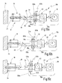
- a drill 10a is shown schematically greatly simplified.
- a drive 36a has a motor 38 and a transmission 42.
- the transmission 42 has a first output 47 and a second output 49.
- the first output 47 is associated with the first transmission stage 46.
- the second output 49 is assigned to the second transmission stage 48.
- a switching device 103a is provided with a coupling 104a, which has partial clutches 118a, 118b.
- the partial clutch 118a is assigned to the second transmission stage 48.
- the partial clutch 118b is assigned to the first transmission stage 46.
- a switching element 106a is configured to alternately selectively open or close the sub-clutch 118a or the sub-clutch 118b. Depending on the position of the switching element 106a, the tool 17 of the first transmission stage 46, 46 'or by means of the second transmission stage 48, 48' are driven.
- Fig. 9a the drill 10a is shown in the center hole configuration.
- the clutch 118a is opened, the clutch 118b is closed.
- the pilot drill 24 can be driven at a high speed range to set a pilot hole, see FIG. the arrow 52.
- the pilot drill is in the first transmission stage 46, 46 'drivable.
- the drill bit 18 can basically be decoupled from the rotational drive, or rotate together with the pilot drill 24.
- Fig. 9b the pilot drill 24 has penetrated into the workpiece 34, furthermore, the drill bit 18 has come to rest on the workpiece 34. In this case, the drill bit 18 has been moved relative to the pilot drill 24, cf. an arrow labeled 94.
- This displacement in the direction of a stop 120 can be detected and produce a switching pulse 122, which may be generated by a control device 56, cf. approximately Fig. 2 , is evaluated to drive the switching element 106a accordingly.
- the switching element 106a is displaced from the partial coupling 118b in the direction of the partial coupling 118a.
- the partial clutch 118a is closed, the partial clutch 118b is opened.
- the Tool 17 can be driven by means of the second transmission stage 48, 48 'in a low speed range, see. such as the arrow 54, which is particularly suitable for core drilling.
- At least the drill bit 18 is operated in the second speed range.
- the pilot drill 24 can be driven as it were in the second speed range, or be selectively excluded from the rotational drive.
- FIGS. 10a to 10c a further core drilling machine 10b is schematically shown greatly simplified in a core drilling operation.
- the core drilling machine 10b has one opposite the FIGS. 9a, 9b modified drive 36b on. Both the first output 47 and the second output 49 of the transmission 42 can be selectively coupled independently with the tool 17 for its rotational drive.
- the first output 47 is associated with the first transmission stage 46 and coupled via the sub-coupling 118b with the pilot drill 24 for the rotational drive.
- the second output 49 is associated with the second transmission stage 48 and coupled via the sub-coupling 118a with the drill bit 18 to the rotational drive.
- Switching elements 106b, 106c can open or close the partial clutches 118a, 118b independently of one another.
- Fig. 10a the partial clutches 118a, 118b are closed.
- the pilot drill 24 is driven in a first speed range, cf. the arrow 52.
- the drill bit 18 is simultaneously driven in a second speed range, see. the arrow 54.
- Fig. 10b If the switching element 106b of the partial clutch 118a is disengaged, the drill bit 18 is decoupled from the second output 49 of the transmission 42. The switching element 106c is engaged, so that a rotational drive of the pilot drill 24 in the first transmission stage 46 takes place. The drill 10b is in the center hole configuration. The total drive power can essentially be supplied to the pilot drill 24.
- Fig. 10c the pilot hole in the workpiece 34 is made.
- the drilling machine 10b is transferred to the core drilling configuration.
- the switching element 106c is disengaged and the switching element 106b is engaged.
- the pilot drill 24 is excluded from the rotational drive.
- the drill bit 18 is driven by means of the second transmission stage 48 in a second, low speed range, see. the arrow 54.
- the entire drive power can be applied essentially for core drilling. When penetrating the drill bit 18 in the workpiece 34, this can relocate relative to the pilot drill 24, which does not penetrate further into the workpiece 34.
- the in the Fig. 10a to 10c Embodiment shown may be approximately as a development of the in the 3 and 4 shown transmission 42 are understood.
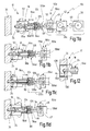
- FIGS. 11a to 11d illustrate another drive 36c in a drill 10c.
- the drive 36c corresponds in its basic structure as the drive 36a according to the FIGS. 9a, 9b ,
- a tool spindle 64 a is provided, which is designed to allow a selective immersion of the pilot drill 24 in order to prevent it from further penetration into the workpiece 34.
- the tool spindle 64a has stop elements 124, for example in the form of balls or rollers.
- the stop elements 124 are secured by a sleeve 126 in a position which allows an axial position limitation of the pilot drill 24 relative to the tool spindle 64a.
- the pilot drill 24 can not be displaced beyond the stop elements 124 against the force of a spring element 84a in the direction of the transmission 42, cf. an arrow labeled 94b.
- the pilot drill 24 can penetrate into the workpiece 34 in the center hole configuration with high feed forces, without the possibility of displacement along the tool spindle 64a beyond the stop elements 124. there can the pilot drill 24 are driven in the first speed range, approximately analogous to in the Fig. 9a, 9b shown embodiment, see. also the arrow 52.
- Fig. 11b the pilot drill 24 has penetrated into the workpiece 34 to some degree.
- the drill bit 18 comes into abutment with the workpiece 34.
- the drill bit 18 is in principle taken longitudinally displaceable relative to the tool spindle 64a independently of the pilot drill 24, cf. an arrow labeled 94a in FIG Fig. 11a ,
- the drill bit 18 may act on the sleeve 126 via plungers 96a, 96b or the like.
- a longitudinal displacement of the drill bit 18 in the direction of the gear 42 also causes a longitudinal displacement of the sleeve 126.
- the drill bit 18 may be made as one piece with the sleeve 126.
- Fig. 11c is the pilot drill 24 opposite the in Fig. 11b shown position further penetrated into the workpiece 34.
- the drill bit 18 has already been moved along the tool spindle 64a in the direction of a stop 120a.
- the sleeve 126 is moved.
- the stop members 124 are in Fig. 11c
- the position shown may also cause a switching pulse 122c, which causes about a shift of the switching element 106d to switch the switching device 103c and the gear 42, respectively.
- Fig. 11d the switching process is completed.
- the drilling machine 10c is in the core drilling configuration.
- the transmission 42 provides the second transmission stage 48, cf. the arrow 54.
- the drill bit 18 has moved the sleeve 126 against the stop 120a.
- feed forces can be transmitted to the drill bit 18, the drill bit 18 can penetrate into the workpiece 34.
- the displacement of the sleeve 126 has released the stop members 124. These are disengaged, the pilot drill 24 can dip beyond the stop elements 124 out against the force of the spring element 84a in the tool spindle 64a in the direction of the transmission 42, see. one designated 94d Arrow.
- the pilot drill 24 is substantially excluded from further penetration into the workpiece 34.
- the total drive power can be transmitted substantially to the drill bit 18.
- Fig. 12 is exemplified a state in which a core hole has been completed.
- the drill bit 18 has completely penetrated the workpiece 34.
- the pilot drill 24 has set an initial pilot bore 130, but has not penetrated beyond it into the workpiece 34.
- the bore has resulted in a drill core 128.
- the drill core 128 can be ejected from the tool bit 64a and the drill bit 18 by an axial displacement of the pilot drill 24 relative to it. The displacement can be initiated by the spring element 84a, cf. also Fig. 11 d.
- the drill 10c can be re-transferred from the core drilling configuration to the centering configuration.
- Fig. 13a shows a first adapter piece 140 with a first drill receptacle 142 for tensioning the pilot drill 24, while Fig. 13b a second adapter piece 146 with a second drill receptacle 148 for clamping the drill bit 18 shows.
- first adapter piece 140 with the pilot drill bit 24 or the second adapter piece 146 with the drill bit 18 is fastened to the tool spindle 64, either the first gear stage 46 or the second gear stage 48 is activated.
- a detection on the tool spindle 64 may be provided, which is controlled via a positive connection with a form-locking element 144 on the first adapter piece 140 or with positive-locking elements 150, 152 on the second adapter piece 146.
Landscapes
- Engineering & Computer Science (AREA)
- Mechanical Engineering (AREA)
- Mining & Mineral Resources (AREA)
- Processing Of Stones Or Stones Resemblance Materials (AREA)
- Earth Drilling (AREA)
Description
- Die Erfindung betrifft eine Bohrmaschine, insbesondere eine handgeführte Kernbohrmaschine, eine Bohrmaschinen-Werkzeug-Kombination und eine Verwendung einer solchen Bohrmaschine.
- Kernbohren ist allgemein bekannt. Beim Kernbohren zerspant ein Kernbohrer, auch als Bohrkrone bezeichnet, eine im Wesentlichen ringförmige Nut um einen Bohrkern eines zu bearbeitenden Werkstoffs. Insbesondere bei großen Bohrdurchmessern und Bohrtiefen ist das Kernbohren besonders produktiv, da nicht der gesamte Bohrungsquerschnitt zerspant werden muss. Kernbohren findet im Allgemeinen breite Anwendung im Bauwesen, etwa beim Bohren von Durchbrüchen in Mauerwerk, Beton oder Gestein.
- Aus der
US 2,345,403 A , die den Oberbegriff des Anspruchs 1 offenbart, ist eine Bohrmaschine mit einem Pilotbohrer und einer lösbaren Bohrkrone bekannt, wobei ferner ein Getriebe vorgesehen ist, das dazu ausgebildet ist, den Pilotbohrer und die Bohrkrone in entgegengesetzten Richtungen rotatorisch anzutreiben. - Zum Bohren insbesondere großer Kernlöcher werden Kernbohrgeräte oder Kernbohrmaschinen üblicherweise mit einem Stativ oder Gestell gekoppelt, das am Werkstück festgelegt wird. Ein solches Bohrstativ soll eine hinreichende Führung beim Bohrvorgang gewährleisten und kann darüber hinaus mit manuell oder motorisch antreibbaren Vorschubantrieben versehen sein. Daneben können die Bohrstative ein beim Bohren entstehendes Gegenmoment aufnehmen bzw. abstützen, dass dem Antriebsmoment entgegengerichtet ist. Somit kann ein Bediener deutlich entlastet werden, die Gefahr von Verklemmungen des Kernbohrers lässt sich deutlich reduzieren.
- Nachteilig bei stativgebundenen Kernbohrmaschinen ist der hohe Zeitbedarf zur Befestigung und zum Ausrichten des Stativs. So können etwa Stative am Mauerwerk mit einer Mehrzahl von Schraubverbindungen festgelegt werden müssen, die wiederum von Hand vorgebohrt werden müssen.
- Zum Bohren von Kernlöchern, insbesondere von Kernlöchern mit verhältnismäßig kleinen Durchmessern, können Kernbohrgeräte ferner von Hand geführt bzw. von Hand gehalten werden. Zur Verbesserung der Führung beim Bohrvorgang können dabei Werkzeuge vorgesehen sein, bei denen die Bohrkrone zum Bohren des Bohrkerns mit einem Zentrierbohrer zum Bohren einer Zentrierbohrung bzw. Pilotbohrung gekoppelt ist. Dabei ist der Zentrierbohrer üblicherweise gegenüber einer Kernbohrkrone in Richtung auf ein zu bearbeitendes Werkstück versetzt, so dass seine Spitze zu Beginn des Bohrvorgangs alleine in das Werkstück eindringen kann, ohne dass es zu einem wesentlichem Eingriff der Bohrkrone mit dem Werkstück kommt. Der Durchmesser des Zentrierbohrers ist dabei kleiner als der Durchmesser der Bohrkrone. Auf diese Weise werden zwar zwei zueinander konzentrische Bohrungen in das Werkstück eingebracht, der Zentrierbohrvorgang wird aber zur Verbesserung der Führung beim handgeführten Kernbohren in Kauf genommen.
- Eine Kernbohrmaschine ist etwa aus der
DE 10 2009 040 513 A1 bekannt. Dabei handelt es sich um eine Kernbohrmaschine mit einer Hohlbohrwelle, die mit einer Antriebseinheit in Rotation versetzt werden kann. Die Kernbohrmaschine ist ferner zur Aufnahme einer Bohrkrone und eines Zentrierbohrers ausgebildet. Es hat sich gegezeigt, dass der Zentrierbohrer die Führung der Kernbohrmaschine beim Bohren einer Kernbohrung mit der Bohrkrone verbessern kann. - Auch bei der Metallbearbeitung wird das Kernbohren genutzt. Da jedoch Kernbohrungen in Metall üblicherweise mit höherer Genauigkeit als etwa Kernbohrungen in Mauerwerk erfolgen müssen, haben zunächst vorrangig Kernbohrgeräte Verbreitung gefunden, die auf Bohrstativen oder Bohrständern geführt sind. Solche Stative können bei metallischen Werkstoffen etwa durch Magnetkraft oder mittels Unterdruck festgelegt werden. Daneben haben sich in jüngerer Zeit auch Anwendungen für ein handgeführtes Kernbohren in Metall ergeben. Es stellen sich dabei besondere Anforderungen an die Zentrierung der Bohrkrone, um etwa ein "Weglaufen" der Bohrkrone zu verhindern. Eine "weggelaufene" Bohrung sorgt für eine erhöhte Neigung zu Verklemmungen oder gar Brüchen des Werkzeugs. Daneben steigt die Wahrscheinlichkeit, dass die entstandene Bohrung nicht genutzt werden kann, da sie der erforderlichen Genauigkeit nicht entspricht.
- Vor diesem Hintergrund liegt der Erfindung die Aufgabe zugrunde, eine Bohrmaschine anzugeben, die ein schnelles und produktives Bohren von Kernbohrungen, insbesondere in metallischen Werkstoffen, bei hoher Genauigkeit erlaubt. Weiterhin soll die Bohrmaschine möglichst einfach bedienbar sein. Ferner soll eine Verwendung einer solchen Bohrmaschine zum Bohren von Kernbohrungen angegeben werden.
- Diese Aufgabe wird erfindungsgemäß gelöst durch eine Bohrmaschine, insbesondere eine handgeführte Kernbohrmaschine, mit einem Antrieb mit einem Motor, der mit einer Werkzeugspindel zu deren Antrieb koppelbar ist, wobei der Antrieb zumindest eine erste Übertragungsstufe und eine zweite Übertragungsstufe erlaubt, einer Zentrieraufnahme zur Aufnahme eines Pilotbohrers und mit einer Werkzeugaufnahme zur Aufnahme einer Bohrkrone, wobei die Bohrkrone und der Pilotbohrer im Wesentlichen konzentrisch zueinander aufnehmbar sind, wobei der Pilotbohrer, insbesondere zum Bohren einer Pilotbohrung, mittels der ersten Übertragungsstufe in einem ersten Drehzahlbereich antreibbar ist, und wobei die Bohrkrone, insbesondere zum Bohren einer Kernbohrung, mittels der zweiten Übertragungsstufe in einem zweiten Drehzahlbereich antreibbar ist, und wobei die Bohrmaschine ferner eine Schalteinrichtung aufweist, die mit dem Antrieb zusammenwirkt und dazu ausgebildet ist, den Antrieb selektiv zumindest in einer Zentrierbohrkonfiguration oder einer Kernbohrkonfiguration zu betreiben, wobei bei der Zentrierbohrkonfiguration zumindest der Pilotbohrer in der ersten Übertragungsstufe antreibbar ist, und wobei bei der Kernbohrkonfiguration zumindest die Bohrkrone in der zweiten Übertragungsstufe antreibbar ist.
- Die Aufgabe der Erfindung wird auf diese Weise gelöst.
- Erfindungsgemäß kann nämlich nunmehr beim Bohren einer Kernbohrung eine Pilotbohrung zur Zentrierung mit einer ersten Werkzeugdrehzahl vorgebohrt werden und die eigentliche Kernbohrung mit einer zweiten Werkzeugdrehzahl gebohrt werden. Somit ist einerseits eine gute Führung der Bohrmaschine beim Bohren gewährleistet. Andererseits erlaubt die erste Übertragungsstufe, den Pilotbohrer mit einer höheren Drehzahl anzutreiben, so dass der Zentriervorgang nicht zu einer wesentlichen Verlängerung der Dauer des Bohrvorgangs führt.
- Eine solche Kernbohrmaschine eignet sich insbesondere zum Einbringen von Kernbohrungen in Metall.
- Die erste Übertragungsstufe kann regelmäßig einen ersten Drehzahlbereich für den Pilotbohrer zur Verfügung stellen, der grundsätzlich höhere Werkzeugdrehzahlen erlaubt als die zweite Übertragungsstufe, die einen zweiten Drehzahlbereich für die Bohrkrone bereitstellt. Die Drehzahlen können dabei etwa auf die Durchmesser des Pilotbohrers bzw. der Bohrkrone angepasst sein. Es lässt sich somit in einfacher Weise eine geeignete Schnittgeschwindigkeit bewirken, die einerseits, insbesondere beim Bohren der Pilotbohrung, auf dem Pilotbohrer abgestimmt ist und andererseits, etwa beim Bohren der Kernbohrung, an die Bohrkrone angepasst ist.
- Das Betreiben des jeweiligen (Teil-)Werkzeugs mit einer angepassten Werkzeugdrehzahl kann dazu beitragen, die Standzeit des Werkzeugs zu erhöhen, die Wärmeentwicklung beim Bohren günstig zu beeinflussen und den Verschleiß zu verringern. Die Leistungsfähigkeit der Bohrmaschine kann insgesamt verbessert werden. Das Führen der Bohrmaschine beim Bohren der Kernbohrung über die Pilotbohrung kann in zuverlässiger Weise dazu beitragen, ein "Weglaufen" des Werkzeugs zu verhindern oder zu verringern. Die Kernbohrung kann maßhaltig ausgeführt werden.
- Zur Bereitstellung der zumindest einen ersten Übertragungsstufe und einer zumindest zweiten Übertragungsstufe kann der Antrieb etwa ein geeignetes Getriebe aufweisen. Der Antrieb kann jedoch ebenso mit einer geeigneten Ansteuerung des Motors versehen sein, die dessen Charakteristik in einer Weise beeinflusst, dass die Werkzeugspindel in verschiedenen Drehzahlbereichen antreibbar ist. Insofern kann der Antrieb etwa auch ein "virtuelles" Getriebe aufweisen.
- Ein solches "virtuelles" Getriebe kann etwa eine gezielte Beeinflussung von Erregerwicklungen eines Elektromotors erlauben. Dabei können beispielsweise Erregerwicklungen zugeschaltet oder abgeschaltet werden, oder Abschnitte der Erregerwicklungen selektiv umgepolt werden, um die Charakteristik des Elektromotors zu beeinflussen. Es können sich somit verschiedene Drehzahl-Drehmoment-Kennlinien ergeben, die eine Getriebefunktionalität ermöglichen. Diese Kennlinien können in einem Drehzahl-Drehmoment-Diagramm etwa voneinander versetzt, insbesondere parallelverschoben sein oder verschiedene Steigungen aufweisen. Insbesondere Drehzahl-Drehmoment-Kennlinien mit unterschiedlicher Steigung können in ihrer Wirkung verschiedenen Stufen etwa eines Schaltgetriebes entsprechen. Zusätzlich oder alternativ kann die Erregerspannung des Motors variiert werden, um die Antriebscharakteristik zu beeinflussen. Die Erregerspannung kann grundsätzlich hinsichtlich Frequenz, absoluter Höhe oder hinsichtlich des Signalverlaufs variiert werden. Ferner ist eine Pulsweitenmodulation der Erregerspannung denkbar.
- Es ist hinzuzufügen, dass die Aufnahme des Pilotbohrers und die Aufnahme der Bohrkrone mittelbar oder unmittelbar an der Werkzeugspindel erfolgen kann. Insbesondere kann etwa die Bohrkrone selbst zumindest einen Teil der Zentrieraufnahme für den Pilotbohrer aufweisen oder umgekehrt der Pilotbohrer einen Teil der Werkzeugaufnahme für die Bohrkrone bereitstellen. Grundsätzlich können die Bohrkrone und der Pilotbohrer als integriertes Werkzeug verstanden werden, wobei der Pilotbohrer und die Bohrkrone miteinander gekoppelt sind. Es ist ebenso denkbar, den Pilotbohrer und die Bohrkrone als separate (Teil-)Werkzeuge vorzusehen und deren Kopplung mittelbar über die Bohrmaschine bereitzustellen.
- Der Bohrvorgang kann etwa in der Zentrierbohrkonfiguration begonnen werden. Beispielsweise dann, wenn der Pilotbohrer tief genug in das Werkstück eingedrungen ist, um eine gute Führung zu gewährleisten, kann die Bohrmaschine in die Kernbohrkonfiguration überführt werden.
- Ein solches "Schalten" des Antriebs zwischen der ersten Übertragungsstufe und der zweiten Übertragungsstufe kann grundsätzlich manuell durch den Bediener erfolgen. Alternativ oder zusätzlich kann das "Schalten" automatisiert erfolgen.
- Die Schalteinrichtung kann dazu beitragen, den Bohrvorgang weiter zu vereinfachen und zu beschleunigen. Die Bohrmaschine kann besonders effizient, insbesondere auch ohne einen weiteren manuellen Steuerungseingriff, betrieben werden.
- Gemäß einer weiteren Ausgestaltung weist der Antrieb ein Getriebe, insbesondere ein mechanisches Getriebe, auf, das dem Motor und der Werkzeugspindel zwischengeschaltet ist, und das in der ersten Übertragungsstufe eine erste Übersetzung und in der zweiten Übertragungsstufe eine zweite Übersetzung bereitstellt.
- Das Getriebe kann etwa als mechanisches Getriebe mit zumindest einem Zahnradsatz ausgeführt sein. Grundsätzlich können jedoch ebenso auch Reibgetriebe, fluidische Getriebe oder Ähnliches vorgesehen sein. Das Getriebe kann ebenso als virtuelles Getriebe ausgeführt sein, wobei dabei insbesondere die Charakteristik des Motors in geeigneter Weise beeinflusst werden kann.
- Das Getriebe kann etwa als Schaltgetriebe, Verteilergetriebe oder als Kombination davon ausgebildet sein. Ein Schaltgetriebe kann zumindest einen Ausgang aufweisen, der mit verschiedenen Übersetzungen angesteuert werden kann. Ein Verteilergetriebe kann in seiner Grundgestaltung eine Mehrzahl von Ausgängen aufweisen, die grundsätzlich gleichzeitig mehrere Übersetzungen bereitstellen können.
- Es ist weiter bevorzugt, wenn das Getriebe zumindest einen ersten Ausgang und einen zweiten Ausgang aufweist, die selektiv mit der Werkzeugspindel zur Drehmitnahme koppelbar sind, wobei der erste Ausgang der ersten Übertragungsstufe zugeordnet ist und wobei der zweite Ausgang der zweiten Übertragungsstufe zugeordnet ist.
- Somit kann das Getriebe sowohl die erste Übertragungsstufe für den Pilotbohrer als auch die zweite Übertragungsstufe für die Bohrkrone bereitstellen. Dies kann grundsätzlich auch gleichzeitig erfolgen.
- Ebenso können etwa der erste Ausgang oder der zweite Ausgang in geeigneter Weise zu- oder abgeschaltet, oder etwa blockiert werden, um die Bohrkrone bzw. den Pilotbohrer selektiv im ersten Drehzahlbereich bzw. im zweiten Drehzahlbereich anzutreiben.
- Insbesondere dann, wenn der erste Ausgang mit dem zweiten Ausgang verblockt ist, kann in einfacher Weise ein Blockieren des Getriebes bzw. des Antriebs herbeigeführt werden. Ein solcher "Getriebestopp" kann etwa zum Lösen eines verklemmten Bohrwerkzeuges genutzt werden.
- Gemäß einer Weiterbildung dieser Ausgestaltung weist die Werkzeugspindel einen ersten Spindelabschnitt und einen zweiten Spindelabschnitt auf, die zueinander verdrehbar sind, wobei der erste Spindelabschnitt mit dem ersten Ausgang und dem Pilotbohrer koppelbar ist, und wobei der zweite Spindelabschnitt mit dem zweiten Ausgang und der Bohrkrone koppelbar ist.
- Auf diese Weise können grundsätzlich gleichzeitig die Zentrierbohrkonfiguration und die Kernbohrkonfiguration bereitgestellt werden. Somit kann das Getriebe etwa als Verteilergetriebe wirken, das permanent zwei Drehzahlen am Abtrieb bereitstellt. Der Pilotbohrer kann mit hoher Drehzahl in das Werkstück eindringen. Die Bohrkrone kann mit einer geeigneten, niedrigen Drehzahl angetrieben werden.
- Bei einer derartigen Gestaltung bedarf es grundsätzlich keines Schaltvorgangs für das Getriebe zwischen der Zentrierbohrkonfiguration und die Kernbohrkonfiguration. Die Bedienbarkeit der Bohrmaschine kann sich wesentlich vereinfachen.
- Es ist jedoch grundsätzlich auch denkbar, den ersten Spindelabschnitt bzw. den zweiten Spindelabschnitt selektiv mit dem ersten Ausgang bzw. dem zweiten Ausgang des Getriebes zu verbinden oder aber von diesen zu trennen. Für die Bohrmaschine können sich somit weitere Anwendungsmöglichkeiten und Betriebsmodi ergeben.
- Gemäß einem weiteren Aspekt der Erfindung weist die Schalteinrichtung zumindest eine Kupplung auf, die dazu ausgebildet ist, zumindest den Pilotbohrer oder die Bohrkrone zur selektiven Drehmitnahme mit der Werkzeugspindel zu koppeln oder freizugeben.
- Die Schalteinrichtung kann struktureller Bestandteil des Getriebes sein oder zumindest funktionell mittelbar oder unmittelbar mit diesem gekoppelt sein.
- Die Kupplung kann vielfältig ausgestaltet sein. Es können darunter eine Bremse, Sperre, ein Freilauf oder Ähnliches verstanden werden. Die Kupplung kann etwa kraftschlüssig, reibschlüssig, formschlüssig oder in geeigneter Kombination mit den zu koppelnden Elementen zusammenwirken.
- Gemäß einer weiteren Ausgestaltung der Erfindung weist die Bohrmaschine eine Steuereinrichtung auf, die dazu ausgebildet ist, abhängig von Betriebszuständen der Bohrmaschine den Antrieb selektiv in die Zentrierbohrkonfiguration oder die Kernbohrkonfiguration zu überführen.
- Hierzu kann die Steuereinrichtung etwa in geeigneter Weise mit der Schalteinrichtung zusammenwirken.
- Gemäß einer Weiterbildung dieser Ausgestaltung ist die Steuereinrichtung mit zumindest einem Sensor, insbesondere einem Kraftsensor, Wegsensor oder Anschlagdetektor, gekoppelt.
- Somit kann die Bohrmaschine grundsätzlich etwa abhängig vom Bohrfortschritt automatisiert von der Zentrierbohrkonfiguration in die Kernbohrkonfiguration überführt werden.
- Ein Kraftsensor kann etwa dazu ausgebildet sein, eine Vorschubkraft, die über den Bediener eingebracht wird, zu erfassen. Das Überschreiten oder Unterschreiten bestimmter Schwellwerte kann als Auslöser des Schaltvorgangs genutzt werden.
- Ein Wegsensor kann dazu ausgebildet sein, eine Bohrtiefe des Pilotbohrers im Werkstück zu erfassen. Somit kann etwa dann, wenn die Bohrtiefe des Pilotbohrers für eine gute Führung der Bohrmaschine ausreichend ist, die Bohrmaschine in die Kernbohrkonfiguration überführt werden.
- Ein Anschlagdetektor kann etwa dazu ausgebildet sein, ein Aufsetzen der Bohrkrone auf dem Werkstück zu erfassen. Das Aufsetzen kann einen Schaltimpuls zum Schalten des Antriebs auslösen.
- Andere Sensoren sind ohne weiteres denkbar. So können etwa verschiedene Zustandsgrößen des Antriebs als Indikator für dessen Belastung herangezogen werden. Eine mittelbare oder unmittelbare Bestimmung eines Moments am Bohrwerkzeug, also etwa am Pilotbohrer oder der Bohrkrone, ist denkbar, um das Aufsetzen bzw. ein in Eingriff bringen der Bohrkrone oder des Pilotbohrers zu erfassen. Darauf basierend kann anschließend ein Schaltvorgang ausgelöst werden.
- Es ist weiter bevorzugt, wenn, etwa nach erfolgtem Bohrvorgang, die Bohrmaschine von der Kernbohrkonfiguration in die Zentrierbohrkonfiguration überführt werden kann. Auf diese Weise kann die Bohrmaschine ohne weitere Vorbereitung für einen neuen Bohrvorgang zur Verfügung stehen.
- Es versteht sich, dass zusätzlich oder alternativ zum Schalten mittels der Steuereinrichtung ebenso eine manuelle Betätigung der Schalteinrichtung ermöglicht sein kann. Ferner kann die Schalteinrichtung dazu ausgebildet sein, selektiv in einem Automatik-Modus oder einem manuellen Modus betrieben zu werden.
- Die Flexibilität der Bohrmaschine kann sich weiter erhöhen. Insbesondere ein versierter Bediener kann die Schalteinrichtung manuell bedienen. Ein unerfahrener Bediener kann das Auslösen des Schaltvorgangs der Steuereinrichtung überlassen.
- Gemäß einem weiteren Aspekt der Erfindung ist zumindest der Pilotbohrer oder die Bohrkrone relativ zur Werkzeugspindel längsverschieblich gelagert.
- Gleichsam kann die Werkzeugspindel trotzdem zur selektiven Drehmitnahme des Pilotbohrers oder der Bohrkrone ausgebildet sein.
- Eine längsverschiebliche Lagerung der Bohrkrone oder des Pilotbohrers kann es erlauben, diese selbst als "Sensor" zu nutzen und, etwa abhängig von deren Axiallage, die Schalteinrichtung auszulösen.
- Ferner kann die Drehmitnahme des Pilotbohrers oder der Bohrkrone durch die Werkzeugspindel abhängig von deren Axiallage aktiviert oder aber deaktiviert werden. Es ist ferner vorstellbar, etwa eine Axialverschiebung der Bohrkrone zu nutzen, um den Pilotbohrer selektiv zuzuschalten oder abzuschalten. Alternativ oder zusätzlich kann die Bohrkrone etwa abhängig von der Axiallage des Pilotbohrers zu- oder abgeschaltet werden.
- Gemäß einer Weiterbildung dieser Ausgestaltung schaltet eine Relativverschiebung der Bohrkrone gegenüber der Werkzeugspindel zumindest eine Kupplung des Pilotbohrers.
- Somit kann insbesondere ein in Eingriff kommen der Bohrkrone eine Deaktivierung des Pilotbohrers ermöglichen. Auf diese Weise kann die Bohrmaschine von der Zentrierbohrkonfiguration in die Kernbohrkonfiguration überführt werden.
- Es ist anzumerken, dass insbesondere bei besonders tiefen Kernbohrungen die Pilotbohrung nicht die gesamte Tiefe der Kernbohrung aufweisen muss. Eine wesentlich geringere Pilotbohrtiefe kann gleichwohl eine gute Führung der Bohrmaschine gewährleisten. Wenn der Pilotbohrer nach Erreichen einer ausreichenden Führungstiefe deaktiviert wird, kann einerseits der Bohrvorgang beschleunigt werden, da dann im Wesentlichen die gesamte Antriebsleistung an der Bohrkrone zur Verfügung stehen kann. Ebenso kann sich die Standzeit insbesondere des Pilotbohrers erhöhen, da dieser nunmehr wesentlich seltener im Eingriff steht.
- Unter einer Deaktivierung kann einerseits ein Lösen der Drehmitnahme des Pilotbohrers durch die Werkzeugspindel verstanden werden. Ebenso kann jedoch auch eine axiale Verschiebung des Pilotbohrers relativ zur Bohrkrone ein weiteres Eindringen des Pilotbohrers in ein zu bohrendes Werkstück verhindern. Dabei kann gleichwohl weiterhin eine Drehmitnahme des Pilotbohrers durch die Werkzeugspindel gegeben sein.
- Gemäß einem weiteren Aspekt der Erfindung ist in der Zentrierbohrkonfiguration zumindest ein Anschlagelement für den Pilotbohrer vorgesehen, das eine Längsverschiebung des Pilotbohrers gegenüber der Werkzeugspindel begrenzt.
- Somit kann beim Bohren der Pilotbohrung im Wesentlichen die gesamte Vorschubkraft auf dem Pilotbohrer einwirken. Ein axiales Ausweichen des Pilotbohrers kann vermieden werden.
- Gemäß einer Weiterbildung dieser Ausgestaltung gibt eine Längsverschiebung der Bohrkrone gegenüber der Werkzeugspindel das zumindest eine Anschlagelement des Pilotbohrers selektiv frei oder rückt dieses ein.
- Somit kann die Bohrkrone in einfacher Weise den Pilotbohrer deaktivieren. Das Deaktivieren kann etwa ein Eintauchen des Pilotbohrers in die Werkzeugspindel erlauben oder eine Entkopplung der Drehmitnahme des Pilotbohrers durch die Werkzeugspindel bewirken.
- Anschlagelemente können etwa als Kugeln, Rollen, Klinken oder Ähnliches ausgestaltet sein. Das zumindest eine Anschlagelement kann zumindest kraftschlüssig oder formschlüssig mit dem Pilotbohrer zusammenwirken.
- Gemäß einem weiteren Aspekt der Erfindung ist zumindest ein Federelement vorgesehen, das eine Rückstellkraft erzeugt, die zumindest auf den Pilotbohrer oder die Bohrkrone in Richtung auf die Zentrierbohrkonfiguration einwirkt.
- Das Federelement kann allgemein als Vorspannelement verstanden werden. Das Federelement kann es etwa ermöglichen, die Bohrmaschine nach erfolgtem Bohrvorgang selbsttätig von der Kernbohrkonfiguration in die Zentrierbohrkonfiguration zu überführen.
- Daneben kann das Federelement grundsätzlich auch dazu beitragen, durch Verschiebung des Pilotbohrers einen Bohrkern aus der Bohrkrone auszuwerfen.
- Besonders bevorzugt ist eine Bohrmaschinen-Werkzeug-Kombination mit einer Bohrmaschine nach einem der oben genannten Aspekte, mit einem Werkzeug, das einen Pilotbohrer und eine Bohrkrone aufweist, wobei der Pilotbohrer und die Bohrkrone konzentrisch zueinander aufnehmbar sind, und wobei insbesondere der Pilotbohrer in der Bohrkrone aufgenommen ist, wobei der Pilotbohrer und die Bohrkrone selektiv rotatorisch antreibbar sind, wobei der Pilotbohrer, insbesondere zum Bohren einer Pilotbohrung, in einem ersten Drehzahlbereich antreibbar ist, wobei die Bohrkrone, insbesondere zum Bohren einer Kernbohrung, in einem zweiten Drehzahlbereich antreibbar ist, und wobei insbesondere zumindest der Pilotbohrer oder die Bohrkrone längsverschieblich auf der Werkzeugspindel aufgenommen sind.
- Gemäß einer weiteren Ausführung der Erfindung ist ein Adapter vorgesehen, der zur Aufnahme an der Werkzeugspindel ausgebildet ist und der eine erste Bohreraufnahme zum Spannen des Pilotbohrers aufweist, und eine zweite Bohreraufnahme zum Spannen der Bohrkrone aufweist, und der in Abhängigkeit von der Aktivierung der ersten Bohreraufnahme beim Spannen des Pilotbohrers die erste Übertragungsstufe aktiviert und bei der Aktivierung der zweiten Bohreraufnahme beim Spannen der Bohrkrone die zweite Übertragungsstufe aktiviert.
- Hierbei kann der Adapter vorteilhaft ein erstes Adapterstück mit der ersten Bohreraufnahme zum Spannen des Pilotbohrers und ein zweites Adapterstück mit der zweiten Bohreraufnahme zum Spannen der Bohrkrone aufweisen, wobei die erste oder zweite Übertragungsstufe in Abhängigkeit davon aktiviert wird, welches Adapterstück an der Werkzeugspindel befestigt ist.
- Die Aufgabe der Erfindung wird ferner gelöst durch eine Bohrmaschinen-Werkzeug-Kombination zum Bohren einer Kernbohrung, insbesondere in einem metallischen Werkstück, wobei eine Pilotbohrung im Wesentlichen in einem ersten Drehzahlbereich gebohrt wird und eine Kernbohrung im Wesentlichen in einem zweiten Drehzahlbereich gebohrt wird, und wobei der Pilotbohrer während des Bohrens der Kernbohrung in der Pilotbohrung verbleibt.
- Die Aufgabe der Erfindung wird schließlich gelöst durch die Verwendung einer Werkzeug-Kombination umfassend einen Pilotbohrer und eine Bohrkrone mit einer Bohrmaschine der vorstehend beschriebenen Art.
- Bei einer solchen Verwendung kann insbesondere bei einer handgeführten Kernbohrmaschine eine gute Führung des Werkzeugs ermöglicht sein. Der Bohrvorgang kann im Wesentlichen kontinuierlich durchgeführt werden, insbesondere ohne dass die Bohrmaschine zwischendurch abgesetzt werden muss.
- Weitere Merkmale und Vorteile der Erfindung ergeben sich aus der nachfolgenden Beschreibung mehrerer bevorzugter Ausführungsbeispiele unter Bezugnahme auf die Zeichnungen. Es zeigen:
- Fig. 1
- eine Seitenansicht einer erfindungsgemäßen Bohrmaschine mit einem Werkzeug zum Kernbohren;
- Fig. 2
- eine vereinfachte schematische Ansicht einer ersten Gestaltung der Bohrmaschine gemäß
Fig. 1 ; - Fig. 3
- einen Schnitt durch ein Getriebe einer erfindungsgemäßen Bohrmaschine;
- Fig. 4
- eine perspektivische Ansicht des Getriebes gemäß
Fig. 3 unter Auslassung des Gehäuses; - Fig. 5
- einen Schnitt durch ein gegenüber
Fig. 3 abgewandeltes Getriebe in einer Zentrierbohrkonfiguration; - Fig. 6
- das Getriebe gemäß
Fig. 5 in einer Kernbohrkonfiguration; - Fig. 7
- einen gebrochenen Schnitt durch das Getriebe gemäß
Fig. 6 entlang der Linie VII-VII; - Fig. 8
- einen Schnitt durch das Getriebe gemäß
Fig. 6 entlang der Linie VIII-VIII; - Fig. 9a, 9b
- eine schematisch stark vereinfachte Darstellung einer weiteren Ausgestaltung der Bohrmaschine gemäß
Fig. 1 beim Bohren einer Pilotbohrung; - Fig. 10a-10c
- eine weitere schematisch stark vereinfachte Darstellung noch einer weiteren Ausgestaltung der Bohrmaschine gemäß
Fig. 1 beim Bohren einer Pilotbohrung; - Fig. 11a-11d
- noch eine weitere schematisch stark vereinfachte Darstellung einer weiteren Ausgestaltung der Bohrmaschine gemäß
Fig. 1 beim Bohren einer Pilotbohrung und einer Kernbohrung; - Fig. 12
- eine vereinfachte schematische gebrochene Ansicht der Bohrmaschine gemäß
Fig. 11a-11d nach dem Kernbohrvorgang; - Fig. 13
- einen Adapter zur Befestigung an der Werkzeugspindel mit einem ersten Adapterstück zum Spannen des Pilotbohrers (
Fig. 13a ) und einem zweiten Adapterstück zum Spannen der Bohrkrone (Fig. 13b ) und zur Steuerung der Übersetzung in Abhängigkeit vom eingesetzten Adapterstück. - In
Fig. 1 ist eine Bohrmaschine dargestellt und insgesamt mit 10 bezeichnet. Die Bohrmaschine 10 ist als handgeführte Kernbohrmaschine ausgebildet. Handgeführte bzw. handgehaltene Kernbohrmaschinen können von einem Bediener zum Bohren von Kernbohrungen oder Ähnlichem verwendet werden, ohne dass es einer separaten Führungsvorrichtung, etwa eines Gestells, Stativs oder eines Bohrständers, bedarf. Somit können Kernbohrungen mit hoher Produktivität bei geringem Zeitaufwand hergestellt werden. - Die Bohrmaschine 10 weist ein Gehäuse 12 auf, das etwa einen Motor und ein Getriebe beherbergt (in
Fig. 1 nicht dargestellt). Am werkzeugseitigen Ende des Gehäuses 12 ist eine Werkzeugaufnahme 14 vorgesehen, die vorliegend eine Hülse 16 aufweist. Die Hülse 16 kann etwa durch Verschieben, Verdrehen oder eine kombinierte Bewegung zwischen einer Freigabestellung und einer Spannstellung verfahren werden. In der Spannstellung ist die Werkzeugaufnahme 14 dazu ausgebildet, ein Werkzeug 17 aufzunehmen und an der Bohrmaschine 10 festzulegen. In der Freigabestellung kann das Werkzeug 17 aus der Werkzeugaufnahme 14 entnommen werden. Ferner kann etwa ein weiteres Werkzeug 17 der Werkzeugaufnahme 14 zugeführt werden. - Das Werkzeug 17 ist vorliegend als Kernbohrwerkzeug ausgebildet. Das Werkzeug 17 weist eine Bohrkrone 18 auf, die mit einem im Wesentlichen rotationssymmetrischen Träger 20 und einem Schnittbereich 22 versehen ist. Der Träger 20 ist etwa napfförmig gestaltet und weist an seiner werkstückseitigen Umfangskante den Schnittbereich 22 auf. Der Schnittbereich 22 kann etwa eine Verzahnung aufweisen. Der Schnittbereich 22 kann mit Schneidmitteln versehen sein, insbesondere abrasiven Schneidmitteln. Alternativ oder zusätzlich ist eine segmentartige Bestückung des Schnittbereichs 22 vorstellbar. Die Verzahnung, Bestückung bzw. die Schneidmittel können insbesondere zum Zerspanen oder Trennen von Metall ausgebildet sein.
- Konzentrisch zur Bohrkrone 18 weist das Werkzeug 17 einen Pilotbohrer 24 auf. Der Pilotbohrer 24 ist dazu ausgebildet, eine Zentrierbohrung oder Pilotbohrung zu bohren, um die Bohrmaschine 10 beim Bohren einer Kernbohrung zu führen. Die Abmessungen der Kernbohrung können sich im Wesentlichen aus einem Durchmesser DK des Schnittbereichs 22 der Bohrkrone 18 und einer freien Tiefe T des Trägers 20 der Bohrkrone 18, abzüglich der Wandstärke der Stirnfläche ergeben. Der Pilotbohrer 24 weist einen Durchmesser DP auf. Der Pilotbohrer 24 kann etwa als Spiralbohrer ausgeführt sein. Insbesondere beim Bohren von Kernbohrungen in Metallwerkstoffen kann der Pilotbohrer 24 als Metallbohrer ausgebildet sein.
- Beim Bohren, insbesondere beim Bohren in Metall, ist eine sog. Schnittgeschwindigkeit, also eine Relativgeschwindigkeit zwischen dem Werkzeug und dem Werkstück von großer Bedeutung für Schnittleistung, Werkzeugstandzeit, Wärmeentwicklung und dergleichen. Insbesondere beim spanabhebenden Bohren hat die Schnittgeschwindigkeit große Auswirkungen auf die Spanbildung. Kriterien für die Auswahl einer geeigneten Schnittgeschwindigkeit können insbesondere ein Werkstoff des Werkzeugs oder ein Werkstoff des zu bearbeitenden Werkstücks sein. Bei gegebener Schnittgeschwindigkeit kann anhand des Werkzeugdurchmessers eine geeignete Werkzeugdrehzahl ermittelt werden. Beim Kernbohren mit der Bohrkrone 18 und dem Pilotbohrer 24 liegen jedoch zwei Durchmesser DK, DP vor, die sich im Regelfall deutlich voneinander unterscheiden. Der Durchmesser DK der Bohrkrone 18 kann etwa zum Durchmesser DP des Pilotbohrers 24 ein Verhältnis von 2:1, 3:1, 5:1 oder gar 10:1 oder höher aufweisen. Folglich kann es von Vorteil sein, das Verhältnis zwischen einer Drehzahl der Bohrkrone 18 und einer Drehzahl des Pilotbohrers 24 in gleicher Weise umgekehrt proportional zueinander zu gestalten. Auf diese Weise können der Pilotbohrer 24 und die Bohrkrone 18 mit zumindest ähnlichen Schnittgeschwindigkeiten betrieben werden.
- Von einer "starren" umgekehrten Proportionalität zwischen den Verhältnissen der Durchmesser und der Drehzahlen bzw. Schnittgeschwindigkeiten der Bohrkrone 18 und des Pilotbohrers 24 kann etwa dann abgewichen werden, wenn sich die Werkstoffe, insbesondere die Schneidwerkstoffe, des Schnittbereichs 22 der Bohrkrone 18 und des Pilotbohrers 24 voneinander unterscheiden. Gleichwohl kann es regelmäßig bevorzugt sein, den Pilotbohrer 24 bei Bohren regelmäßig mit einer höheren Drehzahl als die Bohrkrone 18 anzutreiben. Zu diesem Zweck eignen sich grundsätzlich verschiedene Ausgestaltungen, auf die nachfolgend näher eingegangen wird.
- Die Bohrmaschine 10 in
Fig. 1 weist ferner Griffbereiche 26a, 26b auf, an denen ein Bediener die Bohrmaschine 10 sicher aufnehmen und beim Bohren, etwa bei einer Kernbohrung, führen kann. Insbesondere bei handgeführten Kernbohrmaschinen kann ein beidhändiges Halten und Führen von Vorteil sein, etwa um ein sich beim Bohren ergebendes Gegenmoment aufzunehmen. - Am hinteren Griffbereich 26a ist ein Schalter 28 aufgenommen, mit dem die Bohrmaschine 10 selektiv aktiviert oder deaktiviert werden kann. In
Fig. 1 ist ferner eine Leitung 30 angedeutet, die etwa mit einem Netzanschluss zur Energieversorgung verbunden sein kann. Die Bohrmaschine 10 kann grundsätzlich einen elektrischen Antrieb aufweisen. Ebenso sind pneumatische oder aber hydraulische Antriebe denkbar. - Am Gehäuse 12 ist ferner ein Schalter 32 vorgesehen, der etwa mit einem Getriebe gekoppelt sein kann. Durch Betätigung des Schalters 32 kann der Bediener verschiedene Übersetzungen für das Werkzeug 17 vorwählen und insbesondere den Pilotbohrer 24 in einer ersten Übertragungsstufe und die Bohrkrone 18 in einer zweiten Übertragungsstufe betreiben.
- In
Fig. 2 ist die Bohrmaschine 10 schematisch stark vereinfacht symbolhaft dargestellt. Der äußere Aufbau der Bohrmaschine 10 kann etwa der Gestaltung inFig. 1 entsprechen. - Die Bohrmaschine 10 ist zum Bohren einer Kernbohrung in einem Werkstück 34 ausgebildet. Dabei kann es sich insbesondere um einen metallischen Werkstoff handeln. Die Bohrmaschine 10 weist einen Antrieb 36 auf, der etwa im Gehäuse 12 aufgenommen sein kann, vgl.
Fig. 1 . - Der Antrieb 36 kann einen Motor 38 umfassen, der eine rotatorische Antriebsbewegung bereitstellen kann, vgl. einen mit 40 bezeichneten Pfeil. Der Antrieb 36 weist ferner ein Getriebe 42 auf, das über den Motor 38 antreibbar ist. Das Getriebe 42 weist ein Antriebsritzel 44 auf, mit dem der Motor 38 koppelbar ist.
- Das Antriebsritzel 44 kann mit einer ersten Übertragungsstufe 46 und einer zweiten Übertragungsstufe 48 gekoppelt sein. Die erste Übertragungsstufe 46 dient dabei zum Antrieb des Pilotbohrers 24, vgl. einen gestrichelten Pfeil 46, 46'. Die zweite Übertragungsstufe 48 ist mit der Bohrkrone 18 zu deren Antrieb gekoppelt, vgl. einen Pfeil 48 und einen Blockpfeil 48'. In
Fig. 2 ist ferner schematisch angedeutet, dass die zweite Übertragungsstufe 48 eine größere Untersetzung der Antriebsbewegung 40 des Motors 38 bewirken kann als die erste Übertragungsstufe 46. - Mit anderen Worten ist das Getriebe 42 dazu ausgebildet, die Antriebsbewegung 40 des Motors 38 selektiv in eine Rotation des Pilotbohrers 24 um eine Längsachse 50 bei einer ersten Drehzahl zu überführen, vgl. einen mit 52 bezeichneten Pfeil. Daneben ist das Getriebe 42 dazu ausgebildet, die Antriebsbewegung 40 des Motors 38 selektiv in eine Rotation der Bohrkrone 18 um die Längsachse 50 bei einer zweiten Drehzahl zu überführen, vgl. einen mit 54 bezeichneten Pfeil. Dabei kann die erste Drehzahl 52 grundsätzlich höher als die zweite Drehzahl 54 sein. Der Pilotbohrer 24 kann "schneller" rotieren und somit trotz seines geringeren Durchmessers DP mit einer günstigen Schnittgeschwindigkeit betrieben werden. Die Bohrkrone 18 kann bei grundsätzlich gleicher Drehzahl des Motors 38 "langsamer" rotieren.
- Verschiedene Einrichtungen können mit dem Antrieb 36 bzw. dem Getriebe 42 gekoppelt sein, um den Antrieb 36 etwa während verschiedener Abschnitte eines Bohrvorgangs zu veranlassen, bspw. die erste Übertragungsstufe 46 oder die zweite Übertragungsstufe 48 selektiv zu aktivieren oder aber zu deaktivieren. Hierzu kann etwa der Schalter 32 zur Anwendung kommen, vgl. auch
Fig. 1 . Der Schalter 32 inFig. 2 weist etwa drei Schaltstellungen auf. Beispielhaft kann in einer ersten Schaltstellung I ein Antrieb des Pilotbohrers 24 mittels der ersten Übertragungsstufe 46 gewährleistet sein. In dieser Schaltstufe I kann insbesondere eine Pilotbohrung gesetzt werden, wobei vorzugsweise noch kein Eingriff der Bohrkrone 18 in das Werkstück 34 erfolgt. In einer zweiten Schaltstufe II kann dagegen etwa die Bohrkrone 18 aktiviert werden bzw. mittels der zweiten Übertragungsstufe 48 angetrieben werden. Dies kann bei grundsätzlich geringerer Drehzahl und größerem Drehmoment als der Antrieb des Pilotbohrers 24 in der Schaltstufe I erfolgen. - Daneben weist der Schalter 32 eine dritte Schaltstufe III auf. Die Schaltstufe III kann etwa dazu ausgebildet sein, eine automatische Ansteuerung des Getriebes 42 zu erlauben. Hierzu kann eine Steuereinrichtung 56 vorgesehen sein, die mit Sensoren, etwa einem Kraftsensor 58 oder einem Wegsensor 60, gekoppelt sein kann. Die Sensoren 58, 60 können dazu ausgebildet sein, Zustandsgrößen der Bohrmaschine 10 zu erfassen und an die Steuereinrichtung 56 zu übermitteln. Der Wegsensor 60 kann etwa dazu ausgebildet sein, eine Eindringtiefe des Pilotbohrers 24 zu erfassen. Der Kraftsensor 58 kann etwa dazu ausgebildet sein, eine durch den Bediener aufgebrachte Vorschubkraft zu erfassen und an die Steuereinrichtung 56 zu übermitteln. Andere Sensoren sind denkbar, die etwa die Drehzahl des Motors 38, des Pilotbohrers 24 bzw. der Bohrkrone 18 erfassen. Auch Drehzahlen des Getriebes 42 können überwacht werden. Daneben ist eine Erfassung eines Drehmoments am Motor 38, am Pilotbohrer 24 oder an der Bohrkrone 18 denkbar. Ferner kann etwa eine Relativlage des Pilotbohrers 24 gegenüber der Bohrkrone 18 überwacht werden.
- Abhängig von erfassten Zustandsgrößen der Bohrmaschine 10 kann die Steuereinrichtung 56 ein automatisches Schalten des Getriebes 42 bewirken. Dabei können insbesondere die erste Übertragungsstufe 46 oder die zweite Übertragungsstufe 48 selektiv zugeschaltet, abgeschaltet oder aber gesperrt werden.
- In
Fig. 3 ist das Getriebe 42, etwa der Bohrmaschine 10 gemäßFig. 2 , geschnitten dargestellt.Fig. 4 zeigt eine zugehörige perspektivische Ansicht unter Auslassung des Gehäuses 12. - Das Getriebe 42 ist mit einer Werkzeugspindel 64 gekoppelt, an der das Werkzeug 17 aufgenommen ist. Die Werkzeugspindel 64 weist einen ersten Spindelabschnitt 66 und einen zweiten Spindelabschnitt 68 auf. Die Werkzeugspindel 64 ist über Spindellager 70a, 70b im Gehäuse 12 der Bohrmaschine 10 gelagert. Daneben ist der zweite Spindelabschnitt 68 über Spindellager 72a, 72b im ersten Spindelabschnitt 66 drehbar gelagert.
- In einer Ausnehmung 74 im Inneren der Werkzeugspindel 64 ist ein Schaft 80 des Pilotbohrers 24 angeordnet. Der Pilotbohrer 24 ist ferner an einer Zentrieraufnahme 78 aufgenommen, die der Bohrkrone 18 zugeordnet ist. Die Bohrkrone 18 ist an einer Werkzeugaufnahme 76 des zweiten Spindelabschnitts 68 der Werkzeugspindel 64 aufgenommen. Der erste Spindelabschnitt 66 ist dazu ausgebildet, den Pilotbohrer 24 rotatorisch anzutreiben. Der zweite Spindelabschnitt 68 ist dazu ausgebildet, die Bohrkrone 18 rotatorisch anzutreiben. Die Spindelabschnitte 66, 68 sind relativ zueinander verdrehbar und können gleichzeitig mit verschiedenen Drehzahlen betrieben werden. Somit kann auch der Pilotbohrer 24 relativ zur Bohrkrone 18 verdreht werden.
- Der Pilotbohrer 24 ist als Spiralbohrer ausgebildet und weist eine Schneide 82 auf, die eine Zentrierspitze aufweisen kann. Der Pilotbohrer 24 ist über den Schaft 80 gegen die Kraft eines Federelements 84 in der Ausnehmung 74 des zweiten Spindelabschnitts 68 längsverschieblich angeordnet. Eine durch das Federelement 84 in Richtung auf das Werkstück 34 aufgebrachte Kraft auf den Pilotbohrer 24 kann etwa dazu genutzt werden, diesen zu verlagern, um einen Bohrkern nach erfolgter Bohrung aus dem Werkzeug 17 auszuwerfen, vgl. hierzu etwa
Fig. 12 . - Das Getriebe 42 weist eine Eingangswelle 86 auf, die über das Antriebsritzel 44 antreibbar ist, das mit einem Rad 88a gekoppelt ist. Das Antriebsritzel 44 kann ferner mit dem Motor 38 gekoppelt sein, vgl.
Fig. 2 . Die Eingangswelle 86 weist ein Ritzel 90a auf, vgl.Fig. 4 . Das Ritzel 90a ist mit einem Rad 88b einer Zwischenwelle 92 gekoppelt. Die Zwischenwelle 92 weist ferner ein Ritzel 90b und ein weiteres Ritzel 90c auf. Das Ritzel 90b ist mit einem Rad 88c gekoppelt, das am zweiten Spindelabschnitt 68 angeordnet ist. Das Ritzel 90c ist mit einem Rad 88d gekoppelt, das am ersten Spindelabschnitt 66 angeordnet ist. Das Ritzel 90c und das Rad 88d sind in der ersten Übertragungsstufe 46 zugeordnet, die vorrangig zum Antrieb des Pilotbohrers 24 dient. Das Ritzel 90b und das Rad 88c sind der zweiten Übertragungsstufe 48 zugeordnet, die vorrangig zum Antrieb der Bohrkrone 18 dient. Die Bohrkrone 18 kann grundsätzlich mit einer geringeren Drehzahl als der Pilotbohrer 24 angetrieben werden. - Das in den
Figuren 3 und 4 gezeigte Getriebe 42 kann als Verteilergetriebe verstanden werden. Das Getriebe 42 ist dazu ausgebildet, gleichzeitig mittels der ersten Übertragungsstufe 46 eine erste Drehzahl am ersten Spindelabschnitt 66 und mittels der zweiten Übertragungsstufe 48 eine zweite Drehzahl am zweiten Spindelabschnitt 68 bereitzustellen. Somit können der Pilotbohrer 24 und die Bohrkrone 18 grundsätzlich gleichzeitig in jeweils geeigneten Drehzahlbereichen angetrieben werden. - Ferner können grundsätzlich auch Elemente vorgesehen sein, die dazu ausgebildet sind, selektiv zumindest den Antrieb oder einen Vorschub des Pilotbohrers 24 oder der Bohrkrone 18 zu unterbinden.
- In Zusammenschau ist in den
Figuren 5 bis 8 eine weitere Ausgestaltung eines Getriebes 42a gezeigt, das grundsätzlich ebenso in der Kernbohrmaschine 10 gemäßFig. 1 verbaut sein kann. - Das Getriebe 42a weist einen der Gestaltung des Getriebes 42 gemäß
Fig. 3 ähnlichen Grundaufbau auf. Es ist beim Getriebe 42a jedoch eine abgewandelte Funktionalität vorgesehen. - Das Getriebe 42a ist schaltbar. Das Schalten des Getriebes 42a kann grundsätzlich manuell über den Schalter 32 erfolgen, vgl.
Fig. 1 und 2 . Daneben ist ein automatisiertes Schalten abhängig von Betriebszuständen der Bohrmaschine 10 durch die Steuereinrichtung 56 möglich, vgl. etwaFig. 2 . - Um eine Schaltfunktionalität zu erlauben, ist die Bohrkrone 18 gegenüber der Werkzeugspindel 64 längsverschieblich ausgebildet, vgl. ein mit 94 bezeichneten Pfeil. Die Werkzeugspindel 64 ist in den
Figuren 5 bis 8 im Gegensatz zur inFig. 3 gezeigten Ausgestaltung im Wesentlichen einstückig ausgebildet. Somit ist die Werkzeugspindel 64 grundsätzlich dazu ausgebildet, die Bohrkrone 18 und den Pilotbohrer 24 gemeinsam mit der gleichen Drehzahl anzutreiben. - Das Getriebe 42a ist jedoch schaltbar, so dass etwa bei einem Kernbohrvorgang zunächst ein erster Drehzahlbereich vorgesehen sein kann, bei dem der Pilotbohrer 24 in das Werkstück 34 eindringt. Hiernach kann ein Schaltvorgang erfolgen, danach kann im Wesentlichen die Bohrkrone 18 in einem zweiten Drehzahlbereich angetrieben werden und in das Werkstück 34 eindringen. Der Pilotbohrer 24 kann grundsätzlich parallel im gleichen Drehzahlbereich mitlaufen. Es ist jedoch auch vorstellbar, die Drehmitnahme des Pilotbohrers 24 durch die Spindel 64 zu unterbinden, oder aber den Pilotbohrer 24 am weiteren Eindringen in das Werkstück 34 zu hindern. Hierzu kann etwa vorgesehen sein, den Pilotbohrer 24 in die Ausnehmung 74 der Werkzeugspindel 64 eintauchen zu lassen, wenn die Bohrkrone 18 mit dem Werkstück 34 in Eingriff kommt. Eine solche Ausgestaltung wird beispielhaft nachfolgend anhand der
Figuren 11a-11d näher erläutert. - In
Fig. 5 ist die Bohrkrone 18 an ihrem maschinenseitigen Ende mit Stößeln 96a, 96b gekoppelt und kann diese bei einer Längsverschiebung in Richtung auf das Getriebe 42a relativ zur Spindel 64 verschieben. Die Stößel 96a, 96b sind mit einer Scheibe 98 gekoppelt und können über diese auf ein Druckstück 100 einwirken. Das Druckstück 100 ist durch ein Federelement 102 in Richtung auf das Werkzeug 17 vorgespannt. - Das Druckstück 100 ist dazu ausgebildet, eine Schalteinrichtung 103 zu betätigen, die eine Kupplung 104 aufweist. Hierzu ist das Druckstück 100 mit einem Schaltelement 106 gekoppelt, das etwa als Schaltschieber ausgebildet sein kann. Die Kupplung 104 weist Mitnahmeelemente 110a, 110b auf, die etwa als Kugeln ausgebildet sein können. Die Mitnahmeelemente 110a, 110b können durch das Schaltelement 106 selektiv in Ausnehmungen 112a, 112b der Räder 88d, 88c eingerückt werden. Somit kann die Schalteinrichtung 103 selektiv zumindest einen Antrieb der Werkzeugspindel 64 mittels der ersten Übertragungsstufe 46 oder der zweiten Übertragungsstufe 48 bewirken, vgl. auch
Fig. 6 . - Zu diesem Zweck weist das Schaltelement 106 Raststellen 108a, 108b auf, die die Mitnahmeelemente 110a, 110b abhängig von der Lage des Schaltelements 106 selektiv aufnehmen können, so dass diese aus den Ausnehmungen 112a, 112b ausrücken können.
- In
Fig. 5 ist das Getriebe 42a etwa in einer Zentrierbohrkonfiguration dargestellt. Die Bohrkrone 18 ist nicht in Richtung auf das Getriebe 42a entlang der Werkzeugspindel 64 verschoben. Insbesondere das Federelement 102 kann dabei über das Schaltelement 106, das Druckstück 100, die Scheibe 98 und die Stößel 96a, 96b auf die Bohrkrone 18 einwirken. Mit anderen Worten kann das Federelement 102 dazu beitragen, die Bohrkrone 18 in Richtung auf die Zentrierbohrkonfiguration zu verlagern. In dieser Konfiguration ist das Schaltelement 106 derart bezüglich der Werkzeugspindel 64 angeordnet, dass das Mitnahmeelement 110a aus der Raststelle 108a austreten und in die Ausnehmung 112a des Rades 88d einrücken kann. Das Mitnahmeelement 110b ist aus der Ausnehmung 112b des Rades 88c ausgerückt und in der Raststelle 108b aufgenommen. - Somit wirkt in der in
Fig. 5 gezeigten Konfiguration eine von der Eingangswelle 86 auf die Zwischenwelle 92 übertragene Rotation über das Rad 88d, das der ersten Übertragungsstufe 46 zugehörig ist, auf die Werkzeugspindel 64 ein. Das Rad 88c, das der zweiten Übertragungsstufe 48 zugeordnet ist, ist von der Werkzeugspindel 64 entkoppelt. In der Zentrierbohrkonfiguration kann der Pilotbohrer 24 in einem hohen Drehzahlbereich angetrieben werden, um eine Pilotbohrung zu bohren. - In den
Figuren 6 bis 8 ist das Getriebe 42a etwa in einer Kernbohrkonfiguration dargestellt. Das Schalten der Schalteinrichtung 103 kann durch ein Verschieben der Bohrkrone 18 relativ zur Werkzeugspindel 64 bewirkt werden, vgl. auch den Pfeil 94. Das Verschieben kann etwa durch eine Anlage der Bohrkrone 18 am Werkstück 34 bewirkt werden, vgl. auchFig. 9a und 9b . - Eine Längsführung 114 an der Bohrkrone 18, die mit einem Mitnahmeelement 116 zusammenwirkt, erlaubt eine gewisse Längsverschiebung der Bohrkrone 18 relativ zur Werkzeugspindel 64, obgleich dabei weiterhin eine Drehmitnahme der Bohrkrone 18 gewährleistet ist. Das Mitnahmeelement 116 ist an der Werkzeugspindel 64 aufgenommen. Die Längsverschiebung der Bohrkrone 18 hat in
Fig. 6 ebenso eine Längsverschiebung der Stößel 96a, 96b, der Scheibe 98, des Druckstücks 100 und des Schaltelements 106 in Richtung auf das Getriebe 42a bewirkt. Im Gegensatz zur inFig. 5 gezeigten Zentrierbohrkonfiguration ist in der Kernbohrkonfiguration das Mitnahmeelement 110a aus der Ausnehmung 112a ausgerückt und von der Raststelle 108a aufgenommen, vgl. auchFig. 8 . Das Mitnahmeelement 110b hingegen ist in die Ausnehmung 112b eingerückt und aus der Raststelle 108b hervorgetreten, vgl. auchFig. 7 . Somit ist das Rad 88c, das der zweiten Übertragungsstufe 48 zugeordnet ist, zur Drehmitnahme mit der Werkzeugspindel 64 verbunden. Das Rad 88d, das der ersten Übertragungsstufe 46 zugeordnet ist, ist von der Werkzeugspindel 64 entkoppelt. In der Kernbohrkonfiguration wird die Werkzeugspindel 64 und die Bohrkrone 18 in einem für diese geeigneten Drehzahlbereich angetrieben, der grundsätzlich geringere Drehzahlen als in der Zentrierbohrkonfiguration ermöglicht. - Es ist grundsätzlich vorstellbar, die Schalteinrichtung 103 mit einem Schalter zur manuellen Betätigung, etwa dem Schalter 32, zu koppeln. Somit kann der Bediener einerseits vom automatisierten Schaltvorgang (durch die Verlagerung der Bohrkrone 18) profitieren, andererseits das Getriebe 42a manuell in eine geeignete Stellung überführen.
- In den
Figuren 9a und 9b ist das Setzen eines Pilotlochs eines beispielhaften Kernbohrvorgangs angedeutet. Eine Bohrmaschine 10a ist dabei schematisch stark vereinfacht dargestellt. Ein Antrieb 36a weist einen Motor 38 und ein Getriebe 42 auf. Das Getriebe 42 weist einen ersten Ausgang 47 und einen zweiten Ausgang 49 auf. Der erste Ausgang 47 ist der ersten Übertragungsstufe 46 zugehörig. Der zweite Ausgang 49 ist der zweiten Übertragungsstufe 48 zugeordnet. Eine Schalteinrichtung 103a ist mit einer Kupplung 104a versehen, die Teilkupplungen 118a, 118b aufweist. Die Teilkupplung 118a ist der zweiten Übertragungsstufe 48 zugeordnet. Die Teilkupplung 118b ist der ersten Übertragungsstufe 46 zugeordnet. Ein Schaltelement 106a ist dazu ausgebildet, wechselseitig selektiv die Teilkupplung 118a oder die Teilkupplung 118b zu öffnen oder zu schließen. Abhängig von der Stellung des Schaltelements 106a kann das Werkzeug 17 der ersten Übertragungsstufe 46, 46' oder mittels der zweiten Übertragungsstufe 48, 48' angetrieben werden. - In
Fig. 9a ist die Bohrmaschine 10a in der Zentrierbohrkonfiguration gezeigt. Die Kupplung 118a ist geöffnet, die Kupplung 118b geschlossen. In dieser Konfiguration kann der Pilotbohrer 24 in einem hohen Drehzahlbereich angetrieben werden, um eine Pilotbohrung zu setzen, vgl. den Pfeil 52. Der Pilotbohrer ist in der ersten Übertragungsstufe 46, 46' antreibbar. Dabei kann die Bohrkrone 18 grundsätzlich von der Drehmitnahme entkoppelt sein, oder aber gemeinsam mit dem Pilotbohrer 24 rotieren. - In
Fig. 9b ist der Pilotbohrer 24 in das Werkstück 34 eingedrungen, ferner ist die Bohrkrone 18 zur Anlage am Werkstück 34 gekommen. Dabei ist die Bohrkrone 18 relativ zum Pilotbohrer 24 verschoben worden, vgl. einen mit 94 bezeichneten Pfeil. Dieses Verschieben in Richtung auf einen Anschlag 120 kann detektiert werden und einen Schaltimpuls 122 erzeugen, der etwa von einer Steuereinrichtung 56, vgl. etwaFig. 2 , ausgewertet wird, um das Schaltelement 106a entsprechend anzusteuern. InFig. 9b ist das Schaltelement 106a von der Teilkupplung 118b in Richtung auf die Teilkupplung 118a verlagert. Die Teilkupplung 118a ist geschlossen, die Teilkupplung 118b geöffnet. Das Werkzeug 17 kann mittels der zweiten Übertragungsstufe 48, 48' in einem niedrigen Drehzahlbereich angetrieben werden, vgl. etwa den Pfeil 54, der besonders zum Kernbohren geeignet ist. - In der Kernbohrkonfiguration wird zumindest die Bohrkrone 18 im zweiten Drehzahlbereich betrieben. Der Pilotbohrer 24 kann gleichsam ebenso im zweiten Drehzahlbereich angetrieben werden, oder aber selektiv von der Drehmitnahme ausgenommen sein.
- In den
Figuren 10a bis 10c ist eine weitere Kernbohrmaschine 10b bei einem Kernbohrvorgang schematisch stark vereinfacht dargestellt. - Die Kernbohrmaschine 10b weist einen gegenüber den
Figuren 9a, 9b abgewandelten Antrieb 36b auf. Sowohl der erste Ausgang 47 als auch der zweite Ausgang 49 des Getriebes 42 können unabhängig voneinander selektiv mit dem Werkzeug 17 zu dessen Drehmitnahme gekoppelt werden. Der erste Ausgang 47 ist der ersten Übertragungsstufe 46 zugehörig und über die Teilkupplung 118b mit dem Pilotbohrer 24 zu dessen Drehmitnahme gekoppelt. Der zweite Ausgang 49 ist der zweiten Übertragungsstufe 48 zugeordnet und über die Teilkupplung 118a mit der Bohrkrone 18 zu deren Drehmitnahme gekoppelt. - Schaltelemente 106b, 106c können die Teilkupplungen 118a, 118b unabhängig voneinander öffnen oder schließen. In
Fig. 10a sind die Teilkupplungen 118a, 118b geschlossen. Der Pilotbohrer 24 wird in einem ersten Drehzahlbereich angetrieben, vgl. den Pfeil 52. Die Bohrkrone 18 wird gleichzeitig in einem zweiten Drehzahlbereich angetrieben, vgl. den Pfeil 54. - In
Fig. 10b ist das Schaltelement 106b der Teilkupplung 118a ausgerückt, die Bohrkrone 18 ist vom zweiten Ausgang 49 des Getriebes 42 entkoppelt. Das Schaltelement 106c ist eingerückt, so dass eine Drehmitnahme des Pilotbohrers 24 in der ersten Übertragungsstufe 46 erfolgt. Die Bohrmaschine 10b befindet sich in der Zentrierbohrkonfiguration. Die gesamte Antriebsleistung kann im Wesentlichen dem Pilotbohrer 24 zugeführt werden. - In
Fig. 10c ist die Pilotbohrung im Werkstück 34 hergestellt. Die Bohrmaschine 10b ist in die Kernbohrkonfiguration überführt. Hierzu ist das Schaltelement 106c ausgerückt und das Schaltelement 106b eingerückt. Der Pilotbohrer 24 ist von der Drehmitnahme ausgeschlossen. Die Bohrkrone 18 wird mittels der zweiten Übertragungsstufe 48 in einen zweiten, niedrigen Drehzahlbereich angetrieben, vgl. den Pfeil 54. Die gesamte Antriebsleistung kann im Wesentlichen zum Kernbohren aufgebracht werden. Beim Eindringen der Bohrkrone 18 in das Werkstück 34 kann sich diese relativ zum Pilotbohrer 24 verlagern, der nicht weiter in das Werkstück 34 eindringt. - Die in den
Fig. 10a bis 10c gezeigte Ausgestaltung kann etwa als eine Weiterbildung des in denFig. 3 und 4 gezeigten Getriebes 42 verstanden werden. - Die
Figuren 11a bis 11d veranschaulichen einen weiteren Antrieb 36c bei einer Bohrmaschine 10c. Der Antrieb 36c entspricht in seinem Grundaufbau etwa dem Antrieb 36a gemäß denFiguren 9a, 9b . - Daneben ist jedoch eine Werkzeugspindel 64a vorgesehen, die dazu ausgebildet ist, ein selektives Eintauchen des Pilotbohrers 24 zu erlauben, um diesen vom weiteren Eindringen in das Werkstück 34 abzuhalten. Die Werkzeugspindel 64a weist Anschlagelemente 124 auf, etwa in Form von Kugeln oder Rollen. Die Anschlagelemente 124 sind durch eine Hülse 126 in einer Lage gesichert, die eine axiale Lagebegrenzung des Pilotbohrers 24 gegenüber der Werkzeugspindel 64a ermöglicht. In der in
Fig. 11a gezeigten Konfiguration kann der Pilotbohrer 24 nicht über die Anschlagelemente 124 hinaus gegen die Kraft eines Federelements 84a in Richtung auf das Getriebe 42 verschoben werden, vgl. einen mit 94b bezeichneten Pfeil. - Der Pilotbohrer 24 kann in der Zentrierbohrkonfiguration mit hohen Vorschubkräften in das Werkstück 34 eindringen, ohne dass es zu einer Verlagerung entlang der Werkzeugspindel 64a über die Anschlagelemente 124 hinaus kommen kann. Dabei kann der Pilotbohrer 24 im ersten Drehzahlbereich angetrieben werden, etwa analog zur in den
Fig. 9a, 9b gezeigten Ausgestaltung, vgl. auch den Pfeil 52. - In
Fig. 11b ist der Pilotbohrer 24 zu einem gewissen Grad in das Werkstück 34 eingedrungen. Die Bohrkrone 18 kommt zur Anlage an das Werkstück 34. Die Bohrkrone 18 ist grundsätzlich unabhängig vom Pilotbohrer 24 relativ zur Werkzeugspindel 64a längsverschieblich auf dieser aufgenommen, vgl. einen mit 94a bezeichneten Pfeil inFig. 11a . Die Bohrkrone 18 kann über Stößel 96a, 96b oder Ähnliches auf die Hülse 126 einwirken. Eine Längsverschiebung der Bohrkrone 18 in Richtung auf das Getriebe 42 bewirkt ebenso eine Längsverschiebung der Hülse 126. Alternativ kann die Bohrkrone 18 etwa mit der Hülse 126 einstückig ausgeführt sein. - In
Fig. 11c ist der Pilotbohrer 24 gegenüber der inFig. 11b gezeigten Stellung noch weiter in das Werkstück 34 eingedrungen. Die Bohrkrone 18 ist bereits ein Stück entlang der Werkzeugspindel 64a in Richtung auf einen Anschlag 120a verschoben. Ebenso ist die Hülse 126 verschoben. Die Anschlagelemente 124 sind jedoch inFig. 11c weiterhin durch die Hülse 126 gesichert, so dass ein axiales Verschieben des Pilotbohrers 24 über die Anschlagelemente 124 gerade noch unterbunden wird. Die inFig. 11c gezeigte Stellung kann ferner ein Schaltimpuls 122c bewirken, der etwa eine Verlagerung des Schaltelements 106d bewirkt, um die Schalteinrichtung 103c bzw. das Getriebe 42 zu schalten. - In
Fig. 11d ist der Schaltvorgang abgeschlossen. Die Bohrmaschine 10c befindet sich in der Kernbohrkonfiguration. Das Getriebe 42 stellt die zweite Übertragungsstufe 48 bereit, vgl. den Pfeil 54. - Die Bohrkrone 18 hat die Hülse 126 gegen den Anschlag 120a verschoben. Somit können Vorschubkräfte auf die Bohrkrone 18 übertragen werden, die Bohrkrone 18 kann in das Werkstück 34 eindringen. Das Verschieben der Hülse 126 hat die Anschlagelemente 124 freigegeben. Diese sind ausgerückt, der Pilotbohrer 24 kann über die Anschlagelemente 124 hinaus gegen die Kraft des Federelementes 84a in die Werkzeugspindel 64a in Richtung auf das Getriebe 42 eintauchen, vgl. einen mit 94d bezeichneten Pfeil. Dabei ist der Pilotbohrer 24 im Wesentlichen von weiterem Eindringen in das Werkstück 34 ausgenommen. Somit kann die gesamte Antriebsleistung im Wesentlichen auf die Bohrkrone 18 übertragen werden.
- In
Fig. 12 ist beispielhaft ein Zustand dargestellt, bei dem eine Kernbohrung abgeschlossen wurde. Die Bohrkrone 18 hat das Werkstück 34 vollständig durchdrungen. Der Pilotbohrer 24 hat eine initiale Pilotbohrung 130 gesetzt, ist jedoch über diese hinaus nicht weiter in das Werkstück 34 eingedrungen. Die Bohrung hat einen Bohrkern 128 ergeben. Der Bohrkern 128 kann etwa durch eine Axialverschiebung des Pilotbohrers 24 relativ zur Werkzeugspindel 64a und zur Bohrkrone 18 aus dieser ausgeworfen werden. Die Verschiebung kann durch das Federelement 84a eingeleitet werden, vgl. auchFig. 11 d. Gleichzeitig kann dabei die Bohrmaschine 10c von der Kernbohrkonfiguration erneut in die Zentrierbohrkonfiguration überführt werden. - In
Fig. 13 ist schließlich ein Adapter mit zwei Adapterstücken zum Spannen des Pilotbohrers 24 bzw. zum Spannen der Bohrkrone 18 gezeigt. -
Fig. 13a zeigt ein erstes Adapterstück 140 mit einer ersten Bohreraufnahme 142 zum Spannen des Pilotbohrers 24, währendFig. 13b ein zweites Adapterstück 146 mit einer zweiten Bohreraufnahme 148 zum Spannen der Bohrkrone 18 zeigt. Je nachdem, ob das erste Adapterstück 140 mit dem Pilotbohrer 24 oder das zweite Adapterstück 146 mit der Bohrkrone 18 an der Werkzeugspindel 64 befestigt wird, wird entweder die erste Übersetzungsstufe 46 oder die zweite Übersetzungsstufe 48 aktiviert. Hierzu kann beispielsweise eine Erkennung an der Werkzeugspindel 64 vorgesehen sein, die über einen Formschluss mit einem Formschlusselement 144 am ersten Adapterstück 140 bzw. mit Formschlusselementen 150, 152 am zweiten Adapterstück 146 gesteuert wird.
Claims (14)
- Bohrmaschine, insbesondere handgeführte Kernbohrmaschine, mit einem Antrieb (36) mit einem Motor (38), der mit einer Werkzeugspindel (64) zu deren Antrieb koppelbar ist, wobei der Antrieb (36) zumindest eine erste Übertragungsstufe (46) und eine zweite Übertragungsstufe (48) erlaubt, einer Zentrieraufnahme (78) zur Aufnahme eines Pilotbohrers (24) und mit einer Werkzeugaufnahme (76) zur Aufnahme einer Bohrkrone (18), wobei die Bohrkrone (18) und der Pilotbohrer (24) im Wesentlichen konzentrisch zueinander aufnehmbar sind, wobei der Pilotbohrer (24), insbesondere zum Bohren einer Pilotbohrung, mittels der ersten Übertragungsstufe (46) in einem ersten Drehzahlbereich antreibbar ist, und wobei die Bohrkrone (18), insbesondere zum Bohren einer Kernbohrung, mittels der zweiten Übertragungsstufe (48) in einem zweiten Drehzahlbereich antreibbar ist, gekennzeichnet durch eine Schalteinrichtung (103), die mit dem Antrieb (36) zusammenwirkt und dazu ausgebildet ist, den Antrieb (36) selektiv zumindest in einer Zentrierbohrkonfiguration oder einer Kernbohrkonfiguration zu betreiben, wobei bei der Zentrierbohrkonfiguration zumindest der Pilotbohrer (24) in der ersten Übertragungsstufe (46) antreibbar ist, und wobei bei der Kernbohrkonfiguration zumindest die Bohrkrone (18) in der zweiten Übertragungsstufe (48) antreibbar ist.
- Bohrmaschine (10) nach Anspruch 1, dadurch gekennzeichnet, dass der Antrieb (36) ein Getriebe (42), insbesondere ein mechanisches Getriebe, aufweist, das dem Motor (38) und der Werkzeugspindel (64) zwischengeschaltet ist, und das in der ersten Übertragungsstufe (46) eine erste Übersetzung und in der zweiten Übertragungsstufe (48) eine zweite Übersetzung bereitstellt, wobei das Getriebe (42) vorzugsweise zumindest einen ersten Ausgang (47) und einen zweiten Ausgang (49) aufweist, die selektiv mit der Werkzeugspindel (64) zur Drehmitnahme koppelbar sind, wobei der erste Ausgang (47) der ersten Übertragungsstufe (46) zugeordnet ist und wobei der zweite Ausgang (49) der zweiten Übertragungsstufe (48) zugeordnet ist.
- Bohrmaschine (10) nach Anspruch 2, dadurch gekennzeichnet, dass die Werkzeugspindel (64) einen ersten Spindelabschnitt (66) und einen zweiten Spindelabschnitt (68) aufweist, die zueinander verdrehbar sind, wobei der erste Spindelabschnitt (66) mit dem ersten Ausgang (47) und dem Pilotbohrer (24) koppelbar ist, und wobei der zweite Spindelabschnitt (68) mit dem zweiten Ausgang (49) und der Bohrkrone (18) koppelbar ist.
- Bohrmaschine (10) nach einem der vorhergehenden Ansprüche, dadurch gekennzeichnet, dass die Schalteinrichtung (103) zumindest eine Kupplung (104) aufweist, die dazu ausgebildet ist, zumindest den Pilotbohrer (24) oder die Bohrkrone (18) zur selektiven Drehmitnahme mit der Werkzeugspindel (64) zu koppeln oder freizugeben.
- Bohrmaschine (10) nach einem der vorhergehenden Ansprüche, gekennzeichnet durch eine Steuereinrichtung (56), die dazu ausgebildet ist, abhängig von Betriebszuständen der Bohrmaschine (10) den Antrieb (36) selektiv in die Zentrierbohrkonfiguration oder die Kernbohrkonfiguration zu überführen.
- Bohrmaschine (10) nach Anspruch 5, dadurch gekennzeichnet, dass die Steuereinrichtung (56) mit zumindest einem Sensor (58, 60), insbesondere einem Kraftsensor, Wegsensor oder Anschlagdetektor, gekoppelt ist.
- Bohrmaschine (10) nach einem der vorhergehenden Ansprüche, dadurch gekennzeichnet, dass zumindest der Pilotbohrer (24) oder die Bohrkrone (18) relativ zur Werkzeugspindel (64) längsverschieblich gelagert ist.
- Bohrmaschine (10) nach Anspruch 7, dadurch gekennzeichnet, dass eine Relativverschiebung der Bohrkrone (18) gegenüber der Werkzeugspindel (64) zumindest eine Kupplung (118b) des Pilotbohrers (24) schaltet.
- Bohrmaschine (10) nach Anspruch 7 oder 8, dadurch gekennzeichnet, dass in der Zentrierbohrkonfiguration zumindest ein Anschlagelement (124) für den Pilotbohrer (24) vorgesehen ist, das eine Längsverschiebung des Pilotbohrers (24) gegenüber der Werkzeugspindel (64) begrenzt.
- Bohrmaschine (10) nach einem der Ansprüche 7 bis 9, dadurch gekennzeichnet, dass eine Längsverschiebung der Bohrkrone (18) gegenüber der Werkzeugspindel (64) das zumindest eine Anschlagelement (124) des Pilotbohrers (24) selektiv freigibt oder einrückt.
- Bohrmaschine (10) nach einem der vorhergehenden Ansprüche, dadurch gekennzeichnet, dass zumindest ein Federelement (84, 102) vorgesehen ist, das eine Rückstellkraft erzeugt, die zumindest auf den Pilotbohrer (24) oder die Bohrkrone (18) in Richtung auf die Zentrierbohrkonfiguration einwirkt.
- Bohrmaschine nach einem der vorhergehenden Ansprüche, gekennzeichnet durch einen Adapter, der zur Aufnahme an der Werkzeugspindel (64) ausgebildet ist und der eine erste Bohreraufnahme (142) zum Spannen des Pilotbohrers (24) aufweist, und eine zweite Bohreraufnahme (148) zum Spannen der Bohrkrone (18), aufweist, und der in Abhängigkeit von der Aktivierung der ersten Bohreraufnahme (142) beim Spannen des Pilotbohrers (24) die erste Übertragungsstufe (46) aktiviert und bei der Aktivierung der zweiten Bohreraufnahme (148) beim Spannen der Bohrkrone (18) die zweite Übertragungsstufe (48) aktiviert.
- Bohrmaschine nach Anspruch 12, dadurch gekennzeichnet, dass der Adapter ein erstes Adapterstück (140) mit der ersten Bohreraufnahme (148) zum Spannen des Pilotbohrers (24) und ein zweites Adapterstück (146) mit der zweiten Bohreraufnahme(148) zum Spannen der Bohrkrone (18) aufweist, wobei die erste oder zweite Übertragungsstufe (46, 48) in Abhängigkeit davon aktiviert wird, welches Adapterstück (140, 146) an der Werkzeugspindel (64) befestigt ist.
- Bohrmaschinen-Werkzeug-Kombination mit einer Bohrmaschine (10) nach einem der vorhergehenden Ansprüche, mit einem Werkzeug (17), das einen Pilotbohrer (24) und eine Bohrkrone (18) aufweist, wobei der Pilotbohrer (24) und die Bohrkrone (18) konzentrisch zueinander aufnehmbar sind, und wobei insbesondere der Pilotbohrer (24) an der Bohrkrone (18) aufgenommen ist, dadurch gekennzeichnet, dass der Pilotbohrer (24) und die Bohrkrone (18) selektiv rotatorisch antreibbar sind, wobei der Pilotbohrer (24), insbesondere zum Bohren einer Pilotbohrung, in einem ersten Drehzahlbereich antreibbar ist, wobei die Bohrkrone (18), insbesondere zum Bohren einer Kernbohrung, in einem zweiten Drehzahlbereich antreibbar ist, und wobei insbesondere zumindest der Pilotbohrer (24) oder die Bohrkrone (18) längsverschieblich auf der Werkzeugspindel (64) aufgenommen sind.
Applications Claiming Priority (1)
| Application Number | Priority Date | Filing Date | Title |
|---|---|---|---|
| DE102011100278A DE102011100278A1 (de) | 2011-04-28 | 2011-04-28 | Bohrmaschine, insbesondere handgeführte Bohrmaschine |
Publications (2)
| Publication Number | Publication Date |
|---|---|
| EP2517814A1 EP2517814A1 (de) | 2012-10-31 |
| EP2517814B1 true EP2517814B1 (de) | 2014-12-03 |
Family
ID=45887985
Family Applications (1)
| Application Number | Title | Priority Date | Filing Date |
|---|---|---|---|
| EP12160060.5A Active EP2517814B1 (de) | 2011-04-28 | 2012-03-19 | Bohrmaschine, insbesondere handgeführte Kernbohrmaschine |
Country Status (4)
| Country | Link |
|---|---|
| US (1) | US9216459B2 (de) |
| EP (1) | EP2517814B1 (de) |
| CN (1) | CN102756139B (de) |
| DE (1) | DE102011100278A1 (de) |
Families Citing this family (10)
| Publication number | Priority date | Publication date | Assignee | Title |
|---|---|---|---|---|
| DE102012110213B4 (de) * | 2012-10-25 | 2020-10-08 | C. & E. Fein Gmbh | Kernbohrmaschine |
| DE102012110214B4 (de) * | 2012-10-25 | 2020-10-08 | C. & E. Fein Gmbh | Kernbohrmaschine |
| ITCR20130019A1 (it) * | 2013-09-04 | 2015-03-05 | Ital Res & Innovation Srl | Sistema di trasmissione a due alberi coassiali |
| DE102015003909A1 (de) | 2015-03-27 | 2016-09-29 | TRACTO-TECHNlK GmbH & Co. KG | Deckschichtbohrvorrichtung und Verfahren zum Bohren eines Kerns in eine Deckschicht |
| JP6862429B2 (ja) * | 2015-09-03 | 2021-04-21 | ストライカー・コーポレイション | ドリルビット上を摺動するプローブを含む一体形深さゲージを有する、動力外科用ドリル |
| US10339831B2 (en) * | 2015-11-20 | 2019-07-02 | United Arab Emirates University | Smart drill guide device for muscle training of hand drilling operations |
| EP3299100A1 (de) | 2016-09-23 | 2018-03-28 | HILTI Aktiengesellschaft | Kernbohrmeissel |
| CN107415057B (zh) * | 2017-09-18 | 2023-07-07 | 鲁东大学 | 一种墙壁方形线盒开孔钻头 |
| US10779850B2 (en) * | 2018-03-22 | 2020-09-22 | Gyrus Acmi, Inc. | Rotational tissue cutting control device |
| CN116985274B (zh) * | 2023-09-14 | 2024-04-16 | 中国二十二冶集团有限公司 | 一种穿墙电缆沟防辐射施工装置及施工方法 |
Citations (1)
| Publication number | Priority date | Publication date | Assignee | Title |
|---|---|---|---|---|
| CH312072A (de) * | 1953-02-16 | 1955-12-31 | Franz Brenner Maschinen Und We | Vorrichtung zur Herstellung von Bohrungen grösseren Durchmessers im Mauerwerk, beispielsweise für Steckdosen, Ofenrohre und dergleichen. |
Family Cites Families (14)
| Publication number | Priority date | Publication date | Assignee | Title |
|---|---|---|---|---|
| US1195145A (en) * | 1916-08-15 | Tijvglt | ||
| US192793A (en) * | 1877-07-03 | Improvement in wood-boring machines | ||
| US1202782A (en) * | 1912-02-19 | 1916-10-31 | Albert Blauvelt | Drill. |
| US2345403A (en) * | 1941-03-19 | 1944-03-28 | Mcgrew Wallace Milton | Drill conduit for walls |
| US2838962A (en) * | 1953-08-25 | 1958-06-17 | Curtis Corp | Machine tool |
| US2813280A (en) * | 1955-10-12 | 1957-11-19 | Herman M Huffman | Machine tool for drilling and tapping holes |
| DE1950599A1 (de) | 1969-10-08 | 1971-04-15 | Basf Ag | Thermoplastische Formmassen |
| FR2421594A1 (fr) * | 1977-06-20 | 1979-11-02 | Micro Mega Sa | Tete de contre-angle pour piece a main dentaire |
| US4306570A (en) * | 1980-08-20 | 1981-12-22 | Matthews Larry S | Counter rotating biopsy needle |
| DE19717031C1 (de) * | 1997-04-23 | 1998-10-01 | Duss Maschf | Bohrmaschine zur Erzeugung von Ausnehmungen in Wänden |
| DE19950599A1 (de) * | 1999-09-17 | 2001-03-22 | Klemm Bohrtechnik Zweigniederl | Bohrwerkzeug in Form einer Felsbohrschnecke mit Imlochhammer |
| US8465491B2 (en) * | 2006-06-01 | 2013-06-18 | Osteo Innovations Llc | Bone drill |
| WO2010126896A1 (en) * | 2009-04-27 | 2010-11-04 | Visible Assets, Inc | Tool sensor, system and method |
| DE102009040513A1 (de) | 2009-09-02 | 2011-03-03 | C. & E. Fein Gmbh | Kernbohrmaschine mit austauschbarer Bohrkrone |
-
2011
- 2011-04-28 DE DE102011100278A patent/DE102011100278A1/de not_active Withdrawn
-
2012
- 2012-03-19 EP EP12160060.5A patent/EP2517814B1/de active Active
- 2012-04-27 US US13/458,244 patent/US9216459B2/en active Active
- 2012-04-28 CN CN201210134166.3A patent/CN102756139B/zh not_active Expired - Fee Related
Patent Citations (1)
| Publication number | Priority date | Publication date | Assignee | Title |
|---|---|---|---|---|
| CH312072A (de) * | 1953-02-16 | 1955-12-31 | Franz Brenner Maschinen Und We | Vorrichtung zur Herstellung von Bohrungen grösseren Durchmessers im Mauerwerk, beispielsweise für Steckdosen, Ofenrohre und dergleichen. |
Also Published As
| Publication number | Publication date |
|---|---|
| CN102756139B (zh) | 2016-03-16 |
| US9216459B2 (en) | 2015-12-22 |
| EP2517814A1 (de) | 2012-10-31 |
| US20120275874A1 (en) | 2012-11-01 |
| DE102011100278A1 (de) | 2012-10-31 |
| CN102756139A (zh) | 2012-10-31 |
Similar Documents
| Publication | Publication Date | Title |
|---|---|---|
| EP2517814A1 (de) | Bohrmaschine, insbesondere handgeführte Kernbohrmaschine | |
| DE4019895C2 (de) | Verfahren und Vorrichtung zur Steuerung des Betriebs von Elektrohandgeräten | |
| EP1621286B1 (de) | Bohrmaschine, insbesondere Kernlochbohrmaschine | |
| DE60201794T2 (de) | Revolverwerkzeughalter | |
| DE19951040B4 (de) | Sägeblattbefestigungs- und Lösemechanismus für eine Stichsäge | |
| DE3932660C2 (de) | Schlagbohrmaschine mit mechanischer Schlagübertragung | |
| DE69306626T2 (de) | Tragbare Bohrmaschine mit periodisch unterbrochenem Vorschub | |
| DE2242944B2 (de) | Bohrhammer | |
| EP2038090A1 (de) | Elektrohandwerkzeug | |
| EP2517811A1 (de) | Bohrvorrichtung | |
| DD140114A5 (de) | Werkzeugmaschine | |
| EP0566926A1 (de) | Getriebeeinrichtung einer handgeführten Werkzeugmaschine | |
| DE2165066A1 (de) | Schlagbohrmaschine | |
| EP2489473A2 (de) | Schraubersystem mit Magazinschraubvorsatz | |
| DE976044C (de) | Vorrichtung zum Befestigen von Werkzeugen in der Spindel und Hinausdruecken derselben aus der Spindel einer Werkzeugmaschine | |
| DE3316111A1 (de) | Elektrohandwerkzeug mit steuerung fuer verschiedene funktionen | |
| DE102012110214B4 (de) | Kernbohrmaschine | |
| EP1992436A1 (de) | Motorbetriebenen Arbeits-Spindel für eine Werkzeug-Maschine | |
| DE2156153B2 (de) | ||
| EP0995551B1 (de) | Handführbare Werkzeugmaschine, insbesondere Schrauber oder Bohrschrauber | |
| DE2916499C2 (de) | ||
| DE3527971A1 (de) | Grossloch - bohrvorrichtung | |
| DE102012110213B4 (de) | Kernbohrmaschine | |
| DE3333856C2 (de) | Werkzeugaufnahme für Mehrnuthammerbohrer für einen elektropneumatischen Bohrhammer | |
| EP0302998A2 (de) | Werkzeugrevolver für Werkzeugmaschinen |
Legal Events
| Date | Code | Title | Description |
|---|---|---|---|
| PUAI | Public reference made under article 153(3) epc to a published international application that has entered the european phase |
Free format text: ORIGINAL CODE: 0009012 |
|
| AK | Designated contracting states |
Kind code of ref document: A1 Designated state(s): AL AT BE BG CH CY CZ DE DK EE ES FI FR GB GR HR HU IE IS IT LI LT LU LV MC MK MT NL NO PL PT RO RS SE SI SK SM TR |
|
| AX | Request for extension of the european patent |
Extension state: BA ME |
|
| 17P | Request for examination filed |
Effective date: 20130111 |
|
| GRAP | Despatch of communication of intention to grant a patent |
Free format text: ORIGINAL CODE: EPIDOSNIGR1 |
|
| RIC1 | Information provided on ipc code assigned before grant |
Ipc: B23B 51/04 20060101AFI20140527BHEP Ipc: B28D 1/04 20060101ALI20140527BHEP Ipc: B23B 45/00 20060101ALI20140527BHEP Ipc: B28D 1/14 20060101ALI20140527BHEP |
|
| INTG | Intention to grant announced |
Effective date: 20140612 |
|
| GRAS | Grant fee paid |
Free format text: ORIGINAL CODE: EPIDOSNIGR3 |
|
| GRAA | (expected) grant |
Free format text: ORIGINAL CODE: 0009210 |
|
| AK | Designated contracting states |
Kind code of ref document: B1 Designated state(s): AL AT BE BG CH CY CZ DE DK EE ES FI FR GB GR HR HU IE IS IT LI LT LU LV MC MK MT NL NO PL PT RO RS SE SI SK SM TR |
|
| REG | Reference to a national code |
Ref country code: GB Ref legal event code: FG4D Free format text: NOT ENGLISH |
|
| REG | Reference to a national code |
Ref country code: AT Ref legal event code: REF Ref document number: 699063 Country of ref document: AT Kind code of ref document: T Effective date: 20141215 Ref country code: CH Ref legal event code: EP |
|
| REG | Reference to a national code |
Ref country code: IE Ref legal event code: FG4D Free format text: LANGUAGE OF EP DOCUMENT: GERMAN |
|
| REG | Reference to a national code |
Ref country code: DE Ref legal event code: R096 Ref document number: 502012001709 Country of ref document: DE Effective date: 20150115 |
|
| REG | Reference to a national code |
Ref country code: NL Ref legal event code: VDEP Effective date: 20141203 |
|
| PG25 | Lapsed in a contracting state [announced via postgrant information from national office to epo] |
Ref country code: LT Free format text: LAPSE BECAUSE OF FAILURE TO SUBMIT A TRANSLATION OF THE DESCRIPTION OR TO PAY THE FEE WITHIN THE PRESCRIBED TIME-LIMIT Effective date: 20141203 Ref country code: FI Free format text: LAPSE BECAUSE OF FAILURE TO SUBMIT A TRANSLATION OF THE DESCRIPTION OR TO PAY THE FEE WITHIN THE PRESCRIBED TIME-LIMIT Effective date: 20141203 Ref country code: ES Free format text: LAPSE BECAUSE OF FAILURE TO SUBMIT A TRANSLATION OF THE DESCRIPTION OR TO PAY THE FEE WITHIN THE PRESCRIBED TIME-LIMIT Effective date: 20141203 Ref country code: NO Free format text: LAPSE BECAUSE OF FAILURE TO SUBMIT A TRANSLATION OF THE DESCRIPTION OR TO PAY THE FEE WITHIN THE PRESCRIBED TIME-LIMIT Effective date: 20150303 Ref country code: NL Free format text: LAPSE BECAUSE OF FAILURE TO SUBMIT A TRANSLATION OF THE DESCRIPTION OR TO PAY THE FEE WITHIN THE PRESCRIBED TIME-LIMIT Effective date: 20141203 |
|
| REG | Reference to a national code |
Ref country code: LT Ref legal event code: MG4D |
|
| PG25 | Lapsed in a contracting state [announced via postgrant information from national office to epo] |
Ref country code: RS Free format text: LAPSE BECAUSE OF FAILURE TO SUBMIT A TRANSLATION OF THE DESCRIPTION OR TO PAY THE FEE WITHIN THE PRESCRIBED TIME-LIMIT Effective date: 20141203 Ref country code: HR Free format text: LAPSE BECAUSE OF FAILURE TO SUBMIT A TRANSLATION OF THE DESCRIPTION OR TO PAY THE FEE WITHIN THE PRESCRIBED TIME-LIMIT Effective date: 20141203 Ref country code: GR Free format text: LAPSE BECAUSE OF FAILURE TO SUBMIT A TRANSLATION OF THE DESCRIPTION OR TO PAY THE FEE WITHIN THE PRESCRIBED TIME-LIMIT Effective date: 20150304 Ref country code: CY Free format text: LAPSE BECAUSE OF FAILURE TO SUBMIT A TRANSLATION OF THE DESCRIPTION OR TO PAY THE FEE WITHIN THE PRESCRIBED TIME-LIMIT Effective date: 20141203 Ref country code: LV Free format text: LAPSE BECAUSE OF FAILURE TO SUBMIT A TRANSLATION OF THE DESCRIPTION OR TO PAY THE FEE WITHIN THE PRESCRIBED TIME-LIMIT Effective date: 20141203 Ref country code: SE Free format text: LAPSE BECAUSE OF FAILURE TO SUBMIT A TRANSLATION OF THE DESCRIPTION OR TO PAY THE FEE WITHIN THE PRESCRIBED TIME-LIMIT Effective date: 20141203 |
|
| PG25 | Lapsed in a contracting state [announced via postgrant information from national office to epo] |
Ref country code: EE Free format text: LAPSE BECAUSE OF FAILURE TO SUBMIT A TRANSLATION OF THE DESCRIPTION OR TO PAY THE FEE WITHIN THE PRESCRIBED TIME-LIMIT Effective date: 20141203 Ref country code: RO Free format text: LAPSE BECAUSE OF FAILURE TO SUBMIT A TRANSLATION OF THE DESCRIPTION OR TO PAY THE FEE WITHIN THE PRESCRIBED TIME-LIMIT Effective date: 20141203 Ref country code: CZ Free format text: LAPSE BECAUSE OF FAILURE TO SUBMIT A TRANSLATION OF THE DESCRIPTION OR TO PAY THE FEE WITHIN THE PRESCRIBED TIME-LIMIT Effective date: 20141203 Ref country code: PT Free format text: LAPSE BECAUSE OF FAILURE TO SUBMIT A TRANSLATION OF THE DESCRIPTION OR TO PAY THE FEE WITHIN THE PRESCRIBED TIME-LIMIT Effective date: 20150403 Ref country code: SK Free format text: LAPSE BECAUSE OF FAILURE TO SUBMIT A TRANSLATION OF THE DESCRIPTION OR TO PAY THE FEE WITHIN THE PRESCRIBED TIME-LIMIT Effective date: 20141203 |
|
| PG25 | Lapsed in a contracting state [announced via postgrant information from national office to epo] |
Ref country code: IS Free format text: LAPSE BECAUSE OF FAILURE TO SUBMIT A TRANSLATION OF THE DESCRIPTION OR TO PAY THE FEE WITHIN THE PRESCRIBED TIME-LIMIT Effective date: 20150403 Ref country code: PL Free format text: LAPSE BECAUSE OF FAILURE TO SUBMIT A TRANSLATION OF THE DESCRIPTION OR TO PAY THE FEE WITHIN THE PRESCRIBED TIME-LIMIT Effective date: 20141203 |
|
| REG | Reference to a national code |
Ref country code: DE Ref legal event code: R097 Ref document number: 502012001709 Country of ref document: DE |
|
| PLBE | No opposition filed within time limit |
Free format text: ORIGINAL CODE: 0009261 |
|
| STAA | Information on the status of an ep patent application or granted ep patent |
Free format text: STATUS: NO OPPOSITION FILED WITHIN TIME LIMIT |
|
| PG25 | Lapsed in a contracting state [announced via postgrant information from national office to epo] |
Ref country code: DK Free format text: LAPSE BECAUSE OF FAILURE TO SUBMIT A TRANSLATION OF THE DESCRIPTION OR TO PAY THE FEE WITHIN THE PRESCRIBED TIME-LIMIT Effective date: 20141203 Ref country code: MC Free format text: LAPSE BECAUSE OF FAILURE TO SUBMIT A TRANSLATION OF THE DESCRIPTION OR TO PAY THE FEE WITHIN THE PRESCRIBED TIME-LIMIT Effective date: 20141203 Ref country code: LU Free format text: LAPSE BECAUSE OF FAILURE TO SUBMIT A TRANSLATION OF THE DESCRIPTION OR TO PAY THE FEE WITHIN THE PRESCRIBED TIME-LIMIT Effective date: 20150319 |
|
| REG | Reference to a national code |
Ref country code: CH Ref legal event code: PL |
|
| 26N | No opposition filed |
Effective date: 20150904 |
|
| PG25 | Lapsed in a contracting state [announced via postgrant information from national office to epo] |
Ref country code: IT Free format text: LAPSE BECAUSE OF FAILURE TO SUBMIT A TRANSLATION OF THE DESCRIPTION OR TO PAY THE FEE WITHIN THE PRESCRIBED TIME-LIMIT Effective date: 20141203 |
|
| REG | Reference to a national code |
Ref country code: FR Ref legal event code: ST Effective date: 20151130 |
|
| REG | Reference to a national code |
Ref country code: IE Ref legal event code: MM4A |
|
| PG25 | Lapsed in a contracting state [announced via postgrant information from national office to epo] |
Ref country code: IE Free format text: LAPSE BECAUSE OF NON-PAYMENT OF DUE FEES Effective date: 20150319 Ref country code: LI Free format text: LAPSE BECAUSE OF NON-PAYMENT OF DUE FEES Effective date: 20150331 Ref country code: CH Free format text: LAPSE BECAUSE OF NON-PAYMENT OF DUE FEES Effective date: 20150331 |
|
| PG25 | Lapsed in a contracting state [announced via postgrant information from national office to epo] |
Ref country code: FR Free format text: LAPSE BECAUSE OF NON-PAYMENT OF DUE FEES Effective date: 20150331 Ref country code: SI Free format text: LAPSE BECAUSE OF FAILURE TO SUBMIT A TRANSLATION OF THE DESCRIPTION OR TO PAY THE FEE WITHIN THE PRESCRIBED TIME-LIMIT Effective date: 20141203 |
|
| GBPC | Gb: european patent ceased through non-payment of renewal fee |
Effective date: 20160319 |
|
| PG25 | Lapsed in a contracting state [announced via postgrant information from national office to epo] |
Ref country code: MT Free format text: LAPSE BECAUSE OF FAILURE TO SUBMIT A TRANSLATION OF THE DESCRIPTION OR TO PAY THE FEE WITHIN THE PRESCRIBED TIME-LIMIT Effective date: 20141203 |
|
| PG25 | Lapsed in a contracting state [announced via postgrant information from national office to epo] |
Ref country code: GB Free format text: LAPSE BECAUSE OF NON-PAYMENT OF DUE FEES Effective date: 20160319 |
|
| PG25 | Lapsed in a contracting state [announced via postgrant information from national office to epo] |
Ref country code: BG Free format text: LAPSE BECAUSE OF FAILURE TO SUBMIT A TRANSLATION OF THE DESCRIPTION OR TO PAY THE FEE WITHIN THE PRESCRIBED TIME-LIMIT Effective date: 20141203 Ref country code: SM Free format text: LAPSE BECAUSE OF FAILURE TO SUBMIT A TRANSLATION OF THE DESCRIPTION OR TO PAY THE FEE WITHIN THE PRESCRIBED TIME-LIMIT Effective date: 20141203 Ref country code: HU Free format text: LAPSE BECAUSE OF FAILURE TO SUBMIT A TRANSLATION OF THE DESCRIPTION OR TO PAY THE FEE WITHIN THE PRESCRIBED TIME-LIMIT; INVALID AB INITIO Effective date: 20120319 |
|
| PG25 | Lapsed in a contracting state [announced via postgrant information from national office to epo] |
Ref country code: BE Free format text: LAPSE BECAUSE OF NON-PAYMENT OF DUE FEES Effective date: 20150331 |
|
| PG25 | Lapsed in a contracting state [announced via postgrant information from national office to epo] |
Ref country code: TR Free format text: LAPSE BECAUSE OF FAILURE TO SUBMIT A TRANSLATION OF THE DESCRIPTION OR TO PAY THE FEE WITHIN THE PRESCRIBED TIME-LIMIT Effective date: 20141203 |
|
| REG | Reference to a national code |
Ref country code: AT Ref legal event code: MM01 Ref document number: 699063 Country of ref document: AT Kind code of ref document: T Effective date: 20170319 |
|
| PG25 | Lapsed in a contracting state [announced via postgrant information from national office to epo] |
Ref country code: MK Free format text: LAPSE BECAUSE OF FAILURE TO SUBMIT A TRANSLATION OF THE DESCRIPTION OR TO PAY THE FEE WITHIN THE PRESCRIBED TIME-LIMIT Effective date: 20141203 |
|
| PG25 | Lapsed in a contracting state [announced via postgrant information from national office to epo] |
Ref country code: AT Free format text: LAPSE BECAUSE OF NON-PAYMENT OF DUE FEES Effective date: 20170319 |
|
| PG25 | Lapsed in a contracting state [announced via postgrant information from national office to epo] |
Ref country code: AL Free format text: LAPSE BECAUSE OF FAILURE TO SUBMIT A TRANSLATION OF THE DESCRIPTION OR TO PAY THE FEE WITHIN THE PRESCRIBED TIME-LIMIT Effective date: 20141203 |
|
| PGFP | Annual fee paid to national office [announced via postgrant information from national office to epo] |
Ref country code: DE Payment date: 20250319 Year of fee payment: 14 |