EP2518372B1 - Fahrzeug und steuerungsverfahren dafür - Google Patents
Fahrzeug und steuerungsverfahren dafür Download PDFInfo
- Publication number
- EP2518372B1 EP2518372B1 EP10839060.0A EP10839060A EP2518372B1 EP 2518372 B1 EP2518372 B1 EP 2518372B1 EP 10839060 A EP10839060 A EP 10839060A EP 2518372 B1 EP2518372 B1 EP 2518372B1
- Authority
- EP
- European Patent Office
- Prior art keywords
- torque
- clamping force
- transmission member
- continuously variable
- rotation
- Prior art date
- Legal status (The legal status is an assumption and is not a legal conclusion. Google has not performed a legal analysis and makes no representation as to the accuracy of the status listed.)
- Not-in-force
Links
- 238000000034 method Methods 0.000 title claims description 19
- 230000005540 biological transmission Effects 0.000 claims description 172
- 230000007246 mechanism Effects 0.000 claims description 19
- 238000013016 damping Methods 0.000 claims description 18
- 238000011144 upstream manufacturing Methods 0.000 claims description 15
- 238000001514 detection method Methods 0.000 claims description 12
- 238000006073 displacement reaction Methods 0.000 claims description 10
- 230000001133 acceleration Effects 0.000 claims description 3
- 230000009467 reduction Effects 0.000 description 67
- 239000003921 oil Substances 0.000 description 26
- 230000008859 change Effects 0.000 description 12
- 239000010720 hydraulic oil Substances 0.000 description 9
- 239000000446 fuel Substances 0.000 description 7
- 230000001276 controlling effect Effects 0.000 description 5
- 230000003111 delayed effect Effects 0.000 description 4
- 238000010586 diagram Methods 0.000 description 4
- 230000006870 function Effects 0.000 description 4
- 230000009471 action Effects 0.000 description 3
- 230000002596 correlated effect Effects 0.000 description 3
- 230000000875 corresponding effect Effects 0.000 description 3
- 238000005461 lubrication Methods 0.000 description 3
- 230000001143 conditioned effect Effects 0.000 description 2
- 230000000694 effects Effects 0.000 description 2
- 230000004913 activation Effects 0.000 description 1
- 230000001934 delay Effects 0.000 description 1
- 238000007599 discharging Methods 0.000 description 1
- 229920001971 elastomer Polymers 0.000 description 1
- 239000000806 elastomer Substances 0.000 description 1
- 239000002828 fuel tank Substances 0.000 description 1
- 238000002347 injection Methods 0.000 description 1
- 239000007924 injection Substances 0.000 description 1
- 230000010354 integration Effects 0.000 description 1
- 230000002452 interceptive effect Effects 0.000 description 1
- 230000001050 lubricating effect Effects 0.000 description 1
- 238000012544 monitoring process Methods 0.000 description 1
- 239000011347 resin Substances 0.000 description 1
- 229920005989 resin Polymers 0.000 description 1
- 230000004044 response Effects 0.000 description 1
Images


Classifications
-
- F—MECHANICAL ENGINEERING; LIGHTING; HEATING; WEAPONS; BLASTING
- F16—ENGINEERING ELEMENTS AND UNITS; GENERAL MEASURES FOR PRODUCING AND MAINTAINING EFFECTIVE FUNCTIONING OF MACHINES OR INSTALLATIONS; THERMAL INSULATION IN GENERAL
- F16H—GEARING
- F16H61/00—Control functions within control units of change-speed- or reversing-gearings for conveying rotary motion ; Control of exclusively fluid gearing, friction gearing, gearings with endless flexible members or other particular types of gearing
- F16H61/66—Control functions within control units of change-speed- or reversing-gearings for conveying rotary motion ; Control of exclusively fluid gearing, friction gearing, gearings with endless flexible members or other particular types of gearing specially adapted for continuously variable gearings
- F16H61/662—Control functions within control units of change-speed- or reversing-gearings for conveying rotary motion ; Control of exclusively fluid gearing, friction gearing, gearings with endless flexible members or other particular types of gearing specially adapted for continuously variable gearings with endless flexible members
- F16H61/66272—Control functions within control units of change-speed- or reversing-gearings for conveying rotary motion ; Control of exclusively fluid gearing, friction gearing, gearings with endless flexible members or other particular types of gearing specially adapted for continuously variable gearings with endless flexible members characterised by means for controlling the torque transmitting capability of the gearing
-
- F—MECHANICAL ENGINEERING; LIGHTING; HEATING; WEAPONS; BLASTING
- F16—ENGINEERING ELEMENTS AND UNITS; GENERAL MEASURES FOR PRODUCING AND MAINTAINING EFFECTIVE FUNCTIONING OF MACHINES OR INSTALLATIONS; THERMAL INSULATION IN GENERAL
- F16H—GEARING
- F16H55/00—Elements with teeth or friction surfaces for conveying motion; Worms, pulleys or sheaves for gearing mechanisms
- F16H55/02—Toothed members; Worms
- F16H55/14—Construction providing resilience or vibration-damping
-
- F—MECHANICAL ENGINEERING; LIGHTING; HEATING; WEAPONS; BLASTING
- F16—ENGINEERING ELEMENTS AND UNITS; GENERAL MEASURES FOR PRODUCING AND MAINTAINING EFFECTIVE FUNCTIONING OF MACHINES OR INSTALLATIONS; THERMAL INSULATION IN GENERAL
- F16H—GEARING
- F16H57/00—General details of gearing
- F16H57/0006—Vibration-damping or noise reducing means specially adapted for gearings
-
- F—MECHANICAL ENGINEERING; LIGHTING; HEATING; WEAPONS; BLASTING
- F16—ENGINEERING ELEMENTS AND UNITS; GENERAL MEASURES FOR PRODUCING AND MAINTAINING EFFECTIVE FUNCTIONING OF MACHINES OR INSTALLATIONS; THERMAL INSULATION IN GENERAL
- F16H—GEARING
- F16H9/00—Gearings for conveying rotary motion with variable gear ratio, or for reversing rotary motion, by endless flexible members
- F16H9/02—Gearings for conveying rotary motion with variable gear ratio, or for reversing rotary motion, by endless flexible members without members having orbital motion
- F16H9/04—Gearings for conveying rotary motion with variable gear ratio, or for reversing rotary motion, by endless flexible members without members having orbital motion using belts, V-belts, or ropes
- F16H9/12—Gearings for conveying rotary motion with variable gear ratio, or for reversing rotary motion, by endless flexible members without members having orbital motion using belts, V-belts, or ropes engaging a pulley built-up out of relatively axially-adjustable parts in which the belt engages the opposite flanges of the pulley directly without interposed belt-supporting members
- F16H9/16—Gearings for conveying rotary motion with variable gear ratio, or for reversing rotary motion, by endless flexible members without members having orbital motion using belts, V-belts, or ropes engaging a pulley built-up out of relatively axially-adjustable parts in which the belt engages the opposite flanges of the pulley directly without interposed belt-supporting members using two pulleys, both built-up out of adjustable conical parts
- F16H9/18—Gearings for conveying rotary motion with variable gear ratio, or for reversing rotary motion, by endless flexible members without members having orbital motion using belts, V-belts, or ropes engaging a pulley built-up out of relatively axially-adjustable parts in which the belt engages the opposite flanges of the pulley directly without interposed belt-supporting members using two pulleys, both built-up out of adjustable conical parts only one flange of each pulley being adjustable
Definitions
- the present invention relates to a vehicle and a method for controlling the same, and more particularly, to control of a vehicle having a belt-type continuously variable transmission.
- a belt-type continuously variable transmission mounted on a vehicle such as a saddle-riding type vehicle includes one in which the interval between sheaves for sandwiching a belt is changed by an actuator.
- the belt may likely slip relative to the sheaves upon sudden torque fluctuation occurring at the drive wheel due to running on a bad conditioned road. Such slip of the belt is not preferable in view of durability of the belt and the sheaves.
- Patent Document 1 Japanese Patent Laid-open Publication No. 2003-269591
- the closest prior-art document US 6,290,620 B1 describes a continuously variable transmission and method for preventing transmission belt slippage in the case of a sudden change in load torque on the transmission.
- the approach includes one or both of inserting a lag in the transmission with a torsional spring damper or elastomer damper device between the device to be driven and an output shaft of the secondary pulley of the transmission, and inserting a lag in a hydraulic pressure control loop of the transmission compensating for a difference between the rate of torque transmission between the device to be driven and the transmission, and a response rate of the hydraulic pressure control loop to a sudden change in load torque.
- a force for clamping the belt by the sheaves (hereinafter referred to as a clamping force) is increased when the rotation speed of the drive wheel is changed.
- a clamping force a force for clamping the belt by the sheaves
- the clamping force is increased upon estimation, based on a value obtained in integration with an amount of change in the rotation speed of the drive wheel, to the effect that the road on which the vehicle is running is in a bad condition.
- the clamping force is kept increasing even though the torque fluctuation occurring is relatively so small that slip of the belt will not be caused, torque transmission efficiency of the continuously variable transmission may be deteriorated.
- the present invention has been conceived in view of the above described situation, and mainly aims to provide a vehicle and a method for controlling the vehicle capable of preventing slip of the belt of a continuously variable transmission at appropriate timing.
- a vehicle according to the present invention comprises the features of claim 1.
- a method for controlling a vehicle according to a present invention is a method comprising the steps of claim 12.
- the vehicle is a saddle-riding type vehicle or the like.
- a saddle-riding type vehicle is a vehicle in which a user bestrides the seat, including, e.g., a two-wheeled motor vehicle (scooter), a four-wheeled buggy, a snowmobile, and the like.
- the vehicle may be a four-wheeled vehicle in which two or more users sits side by side in the vehicle width direction.
- timing for transmission of torque fluctuation occurring at a drive wheel to the continuously variable transmission is delayed by a torque damping mechanism, it is possible to increase the clamping force by the time when the torque fluctuation is transmitted to the continuously variable transmission. Further, occurrence of torque fluctuation at a drive wheel can be detected based on the state of the torque damping mechanism, it is possible to increase or decrease the clamping force in accordance with a time for transmission of each torque fluctuation to the continuously variable transmission. For example, by increasing the clamping forces of each pair of the stationary sheave and the movable sheave in accordance with a time for transmission of torque fluctuation to the continuously variable transmission, it is possible to prevent slip of the belt.
- FIG. 1 is a side view of a two-wheeled motor vehicle 1 as a vehicle according to one embodiment of the present invention.
- a front fork 4 is provided rotatably and inclined forward and downward.
- a front wheel 2 as a follower wheel is rotatably supported at the lower end of the front fork 4.
- a steering bar 6 extending in the left-right direction is provided to the upper end of the front fork 4.
- An accelerator grip (not shown) for operation by a driver is provided to the right end of the steering bar 6.
- An engine 20 is provided in the lower rear part of the two-wheeled motor vehicle 1.
- the engine 20 includes a cylinder body 21 and a crank case 23. Rotation of the engine 20 is decelerated by the continuously variable transmission 30 and then transmitted to the rear wheel 3 being as a drive wheel. Further, a control device 10 for controlling the engine 20 and the continuously variable transmission 30 is provided above the engine 20.
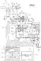
- FIG. 2 schematically shows a torque transmission path and a hydraulic circuit 50 included in the two-wheeled motor vehicle 1.
- a clutch 61, the continuously variable transmission 30, and a cam damper 9 as a torque damping mechanism are provided on the torque transmission path extending from the engine 20 to the rear wheel 3.
- An inlet pipe 24 and an exhaustion pipe 27 are connected to the cylinder body 21 of the engine 20.
- a fuel supply device 26 for supplying fuel from a fuel tank (not shown) to the cylinder body 21 is provided.
- the fuel supply device 26 may be an electronically controlled fuel injection device subjected to control by the control device 10 or a carburetor.
- a throttle body 25 is connected to the inlet pipe 24.
- a throttle valve 25a for adjusting the amount of air flowing into the inlet pipe 24 is provided.
- the throttle valve 25a may be an electronically controlled valve subjected to control by the control device 10 or a valve connected via a wire to the accelerator grip of the steering bar 6.
- the piston 21a provided inside the cylinder body 21 is linked to a crank shaft 23a. When the piston 21a reciprocates due to fuel being combusted, the crank shaft 23a is caused to rotate, as a result of which the engine 20 outputs torque.
- the clutch 61 is provided between the engine 20 and the continuously variable transmission 30, that is, upstream of the continuously variable transmission 30 on the torque transmission path.
- the clutch 61 transmits a torque output from the engine 20 to the continuously variable transmission 30 or inhibits transmission of the torque to the continuously variable transmission 30.
- the clutch 61 is a centrifugal clutch for automatic connection or disconnection depending on the rotation speed of the engine 20.
- the clutch 61 includes a driving member 61a for integral rotation with the crank shaft 23a and a driven member 61c for integral rotation with a primary shaft 36 provided to the continuously variable transmission 30.
- the drive member 61a moves in the radial direction due to a centrifugal force to be brought into contact with the driven member 61c.
- the driven member 61c rotates integrally with the drive member 61a due to a friction force relative to the drive member 61a, whereby the torque of the engine 20 is transmitted via the clutch 61 to the primary shaft 36.
- the continuously variable transmission 30 is a belt-type continuously variable transmission, and includes a first pulley (primary pulley) 31 for integral rotation with the primary shaft 36, a second pulley (secondary pulley) 32 for integral rotation with the secondary shaft 34. Further, the continuously variable transmission 30 has an annular belt 33 wound around the first pulley 31 and the second pulley 32 for transmitting the rotation of the first pulley 31 to the second pulley 32.
- the belt 33 is, e.g., a metallic belt or a resin belt.
- the first pulley 31 includes a first movable sheave (primary sliding sheave) 31a provided for movement in the axial direction of the primary shaft 36 and a first stationary sheave (primary fixed sheave) 31b provided opposite to the first movable sheave 31a in the axial direction.
- the second pulley 32 includes a second movable sheave (secondary sliding sheave) 32a provided for movement in the axial direction of the secondary shaft 34 and a second stationary sheave (secondary fixed sheave) 32b provided opposite to the second movable sheave 32a in the axial direction.
- the reduction ratio of the continuously variable transmission 30 is changed. That is, when the first movable sheave 31a has moved to be closest to the first stationary sheave 31b and the second movable sheave 32a has moved to be farthest from the second stationary sheave 32b, the top reduction ratio (the minimum reduction ratio) is resulted.
- the low reduction ratio (the maximum reduction ratio) is resulted.
- the reduction ratio of the continuously variable transmission 30 changes between the top and the low.
- the continuously variable transmission 30 is a continuously variable transmission of which reduction ratio is controlled by means of hydraulic pressure.
- a first hydraulic chamber (primary hydraulic chamber) 51 is provided to the first pulley 31, to which hydraulic oil is supplied from the second oil passage 59b, and the first movable sheave 31a moves in the axial direction according to the hydraulic pressure in the first hydraulic chamber 51. That is, a first hydraulic actuator 51a for generating a clamping force (first clamping force) for clamping the belt 33 by the first movable sheave 31a and the first stationary sheave 31b is provided to the first pulley 31.
- a second hydraulic chamber (secondary hydraulic chamber) 52 is provided to the second pulley 32, to which hydraulic oil is supplied from the first oil passage 59a, and the second movable sheave 32a moves in the axial direction according to the hydraulic pressure in the second hydraulic chamber 52. That is, a second hydraulic second actuator 52a for generating a clumping force (second lamping force) for clamping the belt 22 by the second movable sheave 32a and the second stationary sheave 32b is provided to the second pulley 32.
- a cam damper 9 is provided between the continuously variable transmission 30 and the rear wheel 3, that is, downstream of the continuously variable transmission 30 on the torque transmission path.
- the rotation having been transmitted from the first pulley 31 of the continuously variable transmission 30 to the second pulley 32 via the belt 22 is further transmitted from the secondary shaft 34 via the cam damper 9 to the axle of the rear wheel 3.
- the cam damper 9 is one example of a torque damping mechanism, and delays timing for transmission of torque fluctuation occurring either upstream or downstream of the cam damper 9 to the other.
- the cam damper 9 includes a first shaft mounted member 92 that is mounted on an intermediate shaft 37, a second shaft mounted member 94, and an elastic member 96, such as a spring or the like, for urging the second shaft mounted member 94 toward the first shaft mounted member 92.
- the first shaft mounted member 92 is mounted for rotation relative to the intermediate shaft 37.
- a following gear 92b is mounted on the first shaft mounted member 92, and meshed with a drive gear 34b provided to the secondary shaft 34 extending from the continuously variable transmission 30.
- the first shaft mounted member 92 rotates integrally with the secondary shaft 34 being as an upstream torque transmission member.
- the second shaft mounted member 94 is spline connected to the intermediate shaft 37 so as to move in the axial direction but be fixed in the circumferential direction.
- the second shaft mounted member 94 rotates integrally with the intermediate shaft 37 being as a downstream torque transmission member.
- the drive shaft 38, linked to the intermediate shaft 37 via a bevel gear, and the axle 39 of the rear wheel 3, linked to the drive shaft 38 via a bevel gear, are also examples of the downstream torque transmission member.
- a concave portion 92a is formed being open toward the second shaft mounted member 94.
- a cam surface 92c that is different in the depth at respective positions thereon in the circumferential direction is formed. Specifically, the cam surface 92c expands in the circumferential direction so as to become deeper as it goes toward the center of the circumferential direction.
- a convex portion 94c is formed projecting toward the first shaft mounted member 92.
- the convex portion 94c has a semi-spherical tip end, and is inserted into the concave portion 92a formed on the first shaft mounted member 92 and urged onto the cam surface 92c by the elastic member 96.
- the position in the circumferential direction of the convex portion 94c in the concave portion 92a is automatically determined at a position where a force with which the cam surface 92c presses the convex portion 94c in the axial direction is balanced with a force with which the elastic member 96 presses the second shaft mounted member 94 in the axial direction.
- a force with which the cam surface 92c presses the convex portion 94c has a correspondence to the magnitude relation of the torque of the secondary shaft 34 and that of the intermediate shaft 37.
- the position in the axial direction of the second shaft mounted member 94 having the convex portion 94c as well is automatically determined. That is, the second shaft mounted member 94 is a displacement member that moves in the axial direction according to the relationship between the torque of the secondary shaft 34 and that of the intermediate shaft 37.
- a back torque input from the rear wheel 3 and transmitted via the axle 39, the drive axis 38, and the intermediate shaft 37 to the cam damper 9 is damped by the action of the elastic member 96 included in the cam damper 9, so that timing for transmission of the back torque to the continuously variable transmission 30 positioned upstream of the cam damper 9 is delayed.
- a back torque input into the rear wheel 3 presents a rectangular waveform that sharply rises
- a back torque transmitted to the continuously variable transmission 30 presents a waveform that gradually rises, which is due to an action of the elastic member 96 included in the cam damper 9.
- the two-wheeled motor vehicle 1 has a brake device 100 for applying brake control to the rear wheel 3.
- the brake device 100 has a real wheel rotation sensor 101 provided in the vicinity of the axle of the rear wheel 3.
- the rear wheel rotation sensor 101 is a rotation detection unit for outputting a pulse signal having a frequency in accordance with the rotation speed of the rear wheel 3.
- the brake device 100 implements brake control, such as anti-lock brake system (ABS), or the like, by utilizing the rotation speed of the rear wheel 3, calculated based on a pulse signal from the rear wheel rotation sensor 101.
- ABS anti-lock brake system
- the hydraulic circuit 50 shown in FIG. 2 is a circuit for generating a hydraulic pressure in accordance with an electric signal input from the transmission control device 14 in the first hydraulic chamber 51 and the second hydraulic chamber 52.
- the hydraulic circuit 50 includes a transmission control valve 55 and a clamping force control valve 56.
- the transmission control valve 55 includes a solenoid valve that operates according to a current supplied from the transmission control device 14 and a pressure reducing valve that operates according to a signal pressure output from the solenoid valve.
- the clamping force control valve 56 includes a solenoid valve that operates according to a current supplied from the transmission control device 14 and a relief valve that operates according to a signal pressure output from the solenoid valve.
- the oil pump 58 is provided so as to operate following the rotation of the engine 20. Specifically, the oil pump 58 sucks hydraulic oil held in the oil sump 57, and supplies to the first oil passage 59a.
- the first oil passage 59a is connected to the second hydraulic chamber 52 and also to the clamping force control valve 56 via an oil passage 59c.
- An oil passage 59d connected to a lubrication path for lubricating the respective parts of the engine 20 and a lubrication path adjusting valve 71 for adjusting the hydraulic pressure in the lubrication path are connected to the clamping force control valve 56.
- the clamping force control valve 56 introduces hydraulic oil from the first oil passage 59a.
- the clamping force control valve 56 operates by adjusting the amount of hydraulic oil to be discharged into the oil passage 59d such that the hydraulic pressure (line pressure) of the first oil passage 59a and that of the second hydraulic chamber 52 become a hydraulic pressure in accordance with the current input from the transmission control device 14.
- the transmission control valve 55 is connected to the first oil passage 59a via the oil passage 59e and also to the first hydraulic chamber 51 via the second oil passage 59b. Further, a discharge path 59f is connected to the transmission control valve 55.
- the transmission control valve 55 generates a hydraulic pressure in accordance with the current input from the transmission control device 14 in the first hydraulic chamber 51. That is, by supplying hydraulic oil introduced from the first oil passage 59a via the oil passage 59e to the second oil passage 59b and also discharging the hydraulic oil in the second oil passage 59b to the discharge path 59f, the transmission control valve 55 operates such that the hydraulic pressure in the first hydraulic chamber 51 becomes one in accordance with the current input from the transmission control device 14.
- a throttle sensor 25b for determining the throttle opening is provided to the throttle body 25.
- the throttle sensor 25b is made using, e.g., a potentiometer, and outputs an electric signal in accordance with the throttle opening.
- An engine rotation speed sensor 23b for outputting a pulse signal having a frequency in accordance with the rotation speed of the crank shaft 23a is provided to the engine 20.
- a primary rotation speed sensor 36a for outputting a pulse signal having a frequency in accordance with the rotation speed of the primary shaft 36 and a secondary rotation speed sensor 34a for outputting a pulse signal having a frequency in accordance with the rotation speed of the secondary shaft 34 are provided to the continuously variable transmission 30.
- a rear wheel rotation sensor 3a as a rotation detection unit for outputting a pulse signal having a frequency in accordance with the rotation speed of the rear wheel 3 is provided.
- engine rotation speed sensor 23b, primary rotation speed sensor 36b, secondary rotation speed sensor 34a, and rear wheel rotation sensor 3a are made respectively using, e.g., a rotation sensor including an electromagnetic pickup and a magnetoresistive element.
- a hydraulic pressure sensor 81 including a diaphragm or a piezo element for outputting an electric signal in accordance with the hydraulic pressure of the first oil passage 59a is provided to the first oil passage 59a.
- a hydraulic pressure sensor 82 similarly including a diaphragm or a piezo element for outputting an electric signal in accordance with the hydraulic pressure of the second oil passage 59b is provided to the second oil passage 59b.
- the control device 10 includes a transmission control device 14 and valve drive circuits 13, 15.
- the transmission control device 14 includes a storage unit 49 made using a RAM (Random Access Memory) and a ROM (Read Only Memory) and a control unit 40 including a microprocessor for executing a program stored beforehand in the storage unit 49.
- a map and a threshold for use in processing by the control unit 40 are stored in advance besides the program executed by the control unit 40.
- Signals output from the engine rotation speed sensor 23b, the primary rotation speed sensor 36a, the secondary rotation speed sensor 34a, and the rear wheel rotation sensor 3a are input to the control unit 40. Based on these output signals, the control unit 40 calculates the engine rotation speed, the rotation speed of the primary shaft 36 (hereinafter referred to as a primary rotation speed), the rotation speed of the secondary shaft 34 (hereinafter referred to as a secondary rotation speed), and the rotation speed of the rear wheel 3. Further, the control unit 40 multiplies the rotation speed of the rear wheel 3 by the gear ratio between the intermediate shaft 37 and the axle 39 to thereby calculate the rotation speed of the intermediate shaft 37. Note that in calculation of the rotation speed of the intermediate shaft 37, the rotation speed of the rear wheel 3 calculated based on a pulse signal from the rear wheel rotation sensor 101 included in the brake device 100 may be used.
- signals output from the hydraulic pressure sensors 81, 82 and the throttle sensor 25b as well are input to the control unit 40.
- the control unit 40 determines the hydraulic pressure of the first hydraulic chamber 51 (hereinafter referred to as a primary pressure), the hydraulic pressure of the second hydraulic chamber 52 (hereinafter referred to as a secondary pressure), and the throttle opening. Based on these information items, the control unit 40 causes the transmission control valve 55 and the clamping force control valve 56 to operate to thereby control the continuously variable transmission 30. Control by the control unit 40 will be described later in detail.
- the respective sensors are connected to the control unit 40 via an interface circuit (not shown) including an A/D converter, or the like, and signals output from the respective sensors are converted in the interface circuit into signals that can be processed by the control unit 40.
- the valve drive circuit 13 supplies a current in accordance with a signal input from the control unit 40 to the solenoid valve that constitutes the transmission control valve 55 to thereby activate the transmission control valve 55. Further, the valve drive circuit 15 supplies a current in accordance with a signal input from the control unit 40 to the solenoid valve that constitutes the clamping force control valve 56 to thereby activate the clamping force control valve 56.
- control device 10 has an engine control device 12 connected thereto via a bus. Signals output from the throttle sensor 25b, the engine rotation speed sensor 23b, and the like, are input also to the engine control device 12 via signal lines (not shown), and based on these output signals, the engine control device 12 controls ignition timing for an ignition plug 29 and the amount of fuel to be injected by the fuel supply device 26.
- FIG. 5 is a block diagram showing a function of the control unit 40 of the transmission control device 14.
- the control unit 40 includes, as functions thereof, a reduction ratio control unit 41 and a clamping force control unit 42.
- the reduction ratio control unit 41 activates the transmission control valve 55 to change the clamping force of the first pulley 31 relative to that of the second pulley 32 to thereby control the reduction ratio.
- the clamping force control unit 42 activates the clamping force control valve 56 to generate a hydraulic pressure free from slip of the belt 33 in the first oil passage 59a and the second hydraulic chamber 52.
- the control unit 40 includes, as functions thereof, an actual reduction ratio calculation unit 43, a secondary clamping force calculation unit 44, and a state information obtaining unit 46.
- the actual reduction ratio calculation unit 43 calculates the reduction ratio of the continuously variable transmission 30.
- the actual reduction ratio calculation unit 43 calculates the reduction ratio of the continuously variable transmission 30, based on the secondary rotation speed (hereinafter referred to as a secondary rotation speed Sspd) and a primary rotation speed (hereinafter referred to as an actual primary rotation speed Pspd).
- the secondary clamping force calculation unit 44 calculates the clamping force of the second pulley 32 (hereinafter referred to as a secondary clamping force Fs).
- the secondary clamping force Fs includes a clamping force generated according to the secondary pressure and a clamping force generated according to the centrifugal force of the hydraulic oil in the second hydraulic chamber 52.
- the secondary clamping force calculation unit 44 calculates the secondary clamping force Fs, based on, e.g., the hydraulic pressure detected by the hydraulic pressure sensor 81 (hereinafter referred to as an actual secondary pressure Ps) and the secondary rotation speed Sspd.
- the state information obtaining unit 46 determines whether or not a back torque has been input into the rear wheel 3. A method for determining occurrence of a back torque will be described later in detail. Upon determination that a back torque has been input into the rear wheel 3, the clamping force control unit 42 executes clamping force changing processing to be described later.
- the clamping force control unit 42 controls the hydraulic pressure of the first oil passage 59a and that of the second hydraulic chamber 52, based on a torque output from the engine 20 (hereinafter referred to as an engine torque T) and a reduction ratio calculated by the actual reduction ratio calculation unit 43 (hereinafter referred to as an actual reduction ratio Rt). Processing by the clamping force control unit 42 is executed as follows, for example.
- the clamping force control unit 42 calculates the engine torque T, based on the throttle opening (hereinafter referred to as a throttle opening Th) and the engine rotation speed (hereinafter referred to as an engine rotation speed Espd). Then, the clamping force control unit 42 calculates a target clamping force of the second pulley 32 (hereinafter referred to as a target secondary clamping force Fs-tg), based on the engine torque T and the actual reduction ratio Rt. For example, with reference to a map and a relational expression stored in the storage unit 49, the clamping force control unit 42 calculates a target secondary clamping force Fs-tg corresponding to the engine torque T and the actual reduction ratio Rt.
- a target secondary clamping force Fs-tg corresponding to the engine torque T and the actual reduction ratio Rt.
- the clamping force control unit 42 calculates a target secondary pressure Ps-tg, based on the target secondary clamping force Fs-tg, calculated as described above. Further, the clamping force control unit 42 supplies a current from the valve drive circuit 15 to the solenoid forming the clamping force control valve 56 such that the actual secondary pressure Ps becomes the same as the target secondary pressure Ps-tg. After activation of the transmission control device 14, the clamping force control unit 42 repetitively executes the above described processing for every predetermined cycle. As a result, the secondary pressure and the hydraulic pressure of the first oil passage 59a are gradually changed, based on a change in the throttle opening Th and the actual reduction ratio Rt.
- the reduction ratio control unit 41 sets a target reduction ratio (hereinafter referred to as a target reduction ratio Rt-tg), based on a driving condition, such as the throttle opening Th, the secondary rotation speed Sspd, and so forth, and controls the reduction ratio such that the actual reduction ratio Rt becomes the same as the target reduction ratio Rt-tg.
- a target reduction ratio Rt-tg a target reduction ratio
- the reduction ratio control unit 41 includes a target reduction ratio calculation unit 41a, a target primary pressure calculation unit 41b, and a valve operation processing unit 41c.
- the target reduction ratio calculation unit 41a calculates a target reduction ratio Rt-tg, based on the throttle opening Th, the secondary rotation speed Sspd, and a vehicle speed obtained based on the rotation speed of the rear wheel 3 (hereinafter referred to as a vehicle speed V). For example, with reference to a map for correlating a throttle opening, a vehicle speed, and a primary rotation speed (hereinafter referred to as a transmission control map) and a relational expression, the target reduction ratio calculation unit 41a calculates a target primary rotation speed Pspd-tg correlated to the throttle opening Th and the vehicle speed V. Thereafter, the target reduction ratio calculation unit 41a divides the target primary rotation speed Pspd-tg by the secondary rotation speed Sspd to thereby calculate the target reduction ratio Rt-tg.
- the target primary pressure calculation unit 41b calculates a target primary pressure (hereinafter referred to as a target primary pressure Pp-tg), based on the actual reduction ratio Rt and the target reduction ratio Rt-tg. This processing by the target primary pressure calculation unit 41b is executed as follows, for example.
- the target primary pressure calculation unit 41b calculates a speed by which to change the reduction ratio (hereinafter referred to as a transmission speed Drt), based on the difference between the actual reduction ratio Rt and the target reduction ratio Rt-tg. For example, with reference to a map for correlating the difference between an actual reduction ratio and a target reduction ratio and a transmission speed (hereinafter referred to as a transmission speed map) and a relational expression, the target primary pressure calculation unit 41b calculates a transmission speed Drt correlated to the difference between the actual reduction ratio Rt calculated by the actual reduction ratio calculation unit 43 and the target reduction ratio Rt-tg calculated by the target reduction ratio calculation unit 41a.
- a transmission speed Drt a speed by which to change the reduction ratio
- the target primary pressure calculation unit 41b adds or subtracts a force in accordance with the transmission speed Drt to or from the clamping force of the first pulley 31 necessary to maintain the current reduction ratio to determine the obtained value as the target clamping force of the first pulley 31 (hereinafter referred to as a target primary clamping force Fp-tg).
- Fpk is a clamping force of the first pulley 31 necessary to maintain the current reduction ratio, being, e.g., a product (Fs ⁇ Rf) of the ratio between the clamping force of the second pulley 32 described above and that of the first pulley 31 (hereinafter referred to as a thrust force ratio Rf).
- the target primary pressure calculation unit 41b calculates a thrust force ratio Rf corresponding to the actual reduction ratio Rt, calculated by the actual reduction ratio calculation unit 43, then calculates the target primary clamping force Fp-tg, based on the thrust force ratio Rf and the secondary clamping force Fs, that is, a clamping force calculated by the secondary clamping force calculation unit 44.
- k indicates a coefficient determined based on the reduction ratio and the primary rotation speed
- the target primary pressure calculation unit 41b calculates a coefficient k correlated to the actual reduction ratio Rt and the actual primary rotation speed Pspd, with reference to the map, wherein Pspd is an actual primary rotation speed determined by the primary rotation speed sensor 36a, as described above.
- the target primary pressure calculation unit 41b calculates the target primary pressure Pp-tg, based on the target primary clamping force Fp-tg, calculated as described above. For example, because the clamping force of the first pulley 31 includes a centrifugal force generated through rotation of the hydraulic oil in the first hydraulic chamber 51, the target primary pressure calculation unit 41b calculates the target primary pressure Pp-tg, based on the actual primary rotation speed Pspd and the pressure receiving area of the first pulley 31 (the area of a portion of the first movable sheave 31a for receiving the hydraulic pressure).
- the valve operation processing unit 41c controls a current to be supplied from the valve drive circuit 13 to the transmission control valve 55 such that the hydraulic pressure of the first hydraulic chamber 51, determined by the hydraulic pressure sensor 82 (hereinafter referred to as an actual primary pressure Pp), becomes the same as the target primary pressure Pp-tg.
- the valve operation processing unit 41c calculates an instruction value, based on the difference between the target primary pressure Pp-tg and the actual primary pressure Pp, and outputs the instruction value to the valve drive circuit 13.
- the valve drive circuit 13 supplies a current of a value in accordance with the instruction value to the transmission control valve 55.
- the difference between the target primary pressure Pp-tg and the actual primary pressure Pp is solved, and the actual reduction ratio Rt becomes closer to the target reduction ratio Rt-tg.
- the target primary pressure calculation unit 41b repetitively executes the above described processing to thereby sequentially update the target primary pressure Pp-tg. That is, every change of the actual reduction ratio Rt toward the target reduction ratio Rt-tg, the target primary pressure calculation unit 41b newly calculates a target primary pressure Pp-tg, based on the difference between the changed actual reduction ratio Rt and the target reduction ratio Rt-tg.
- the valve operation processing unit 41c outputs an instruction value calculated based on the newly calculated target primary pressure Pp-tg and the actual primary pressure Pp to the valve drive circuit 13. As a result, the actual reduction ratio Rt becomes further closer to the target reduction ratio Rt-tg.
- the transmission speed Drt calculated based on the difference between the actual reduction ratio Rt and the target reduction ratio Rt-tg becomes 0.
- the target primary pressure calculation unit 41b calculates a hydraulic pressure corresponding to the clamping force Fpk of the first pulley 31 necessary to maintain the reduction ratio as the target primary pressure Pp-tg.
- the actual reduction ratio Rt is maintained at the target reduction ratio Rt-tg.
- FIG. 6 is a flowchart of an example processing executed by the control unit 40.
- the state information obtaining unit 46 obtains information on a state of the cam damper 9, and determines whether or not a back torque has been input into the rear wheel 3 (S1).
- a first example method for detecting occurrence of a back torque whether or not a back torque has been input into the rear wheel 3 is determined based on whether or not a difference equal to or larger than a predetermined difference is caused between the rotation speed of the secondary shaft 34 and that of the intermediate shaft 37, shown in FIG. 3 .
- a second example method for detecting occurrence of a back torque whether or not a back torque has been input into the rear wheel 3 is determined based on whether or not a phase difference equal to or larger than a predetermined phase difference is caused between the rotation of the secondary shaft 34 and that of the intermediate shaft 37, shown in FIG. 3 . That is, when a back torque is input into the rear wheel 3, in the cam damper 9, the position in the circumferential direction of the convex portion 94c of the second shaft mounted member 94 inserted in the concave portion 92a of the first shaft mounted member 92 is displaced, which causes a phase difference between the rotation of the secondary shaft 34 and that of the intermediate shaft 37.
- phase difference when a phase difference equal to or larger than a predetermined phase difference is caused between the rotation of the secondary shaft 34 and that of the intermediate shaft 37, it is determined that a back torque has been input into the rear wheel 3. Specifically, when the phase of the rotation of the intermediate shaft 37 is delayed relative to that of the secondary shaft 34, it is determined that a back torque has been input into the rear wheel 3.
- phase difference is determined by monitoring a displacement between a pulse signal from the secondary rotation speed sensor 34a and that from the rear wheel rotation sensor 3a, as shown in Fig. 2 .
- a third example method for detecting occurrence of a back torque whether or not a back torque has been input into the rear wheel 3 is determined based on whether or not the second shaft mounted member 94 included in the cam damper 9, shown in FIG. 3 , is displaced in the axial direction by an amount equal to or larger than a predetermined amount. That is, when a back torque is input into the rear wheel 3, in the cam damper 9, a relationship between a force with which the cam surface 92c presses the convex portion 94c in the axial direction and a force with which the elastic member 96 presses the second shaft mounted member 94 in the axial direction is changed, which causes the second shaft mounted member 94 to move in the axial direction.
- FIG. 9 a relationship between a force with which the cam surface 92c presses the convex portion 94c in the axial direction and a force with which the elastic member 96 presses the second shaft mounted member 94 in the axial direction is changed, which causes the second shaft mounted member 94 to move in the
- a displacement sensor 99 for determining the position in the axial direction of the second shaft mounted member 94 is provided so that whether or not a back torque has been input into the rear wheel 3 is determined based on a displacement of the second shaft mounted member 94 in the axial direction. Specifically, when the second shaft mounted member 94 moves in a direction departing from the first shaft mounted member 92, that is, when the second shaft mounted member 94 moves in the direction opposite from the direction in which the second shaft mounted member 94 presses the elastic member 96, it is determined that a back torque has been input into the rear wheel 3.
- the clamping force changing processing unit 42i of the clamping force control unit 42 starts clamping force changing processing for increasing the clamping force of the second pulley 32 (S2). Then, after elapse of a predetermined period of time after the start of the clamping force changing processing (S3: YES), the clamping force changing processing unit 42i ends the clamping force changing processing (S4).
- the clamping force changing processing unit 42i adds a positive value to the target secondary pressure Ps-tg calculated as is in the normal processing described above, to thereby correct the target secondary pressure Ps-tg (hereinafter referred to as a corrected target secondary pressure Ps-tg#). Then, the clamping force control unit 42 supplies a current from the valve drive circuit 15 to the solenoid of the clamping force control valve 56 such that the actual secondary pressure Ps becomes the same as the corrected target secondary pressure Ps-tg#. With the above, the clamping force of the second pulley 32 increases more than in the normal processing.
- the target primary pressure calculation unit 41b calculates the target primary clamping force Fp-tg and the target primary pressure Pp-tg, based on the secondary clamping force Fs calculated by the secondary clamping force calculation unit 44.
- the clamping force of the first pulley 31 as well increases more than in the normal processing along with the increase of the clamping force of the second pulley 32. In this manner, as the clamping forces of the first pulley 31 and the second pulley 32 both increase, slip of the belt 33 can be prevented.
- the clamping force changing processing unit 42i increases the clamping forces of the first pulley 31 and the second pulley 32 such that the torque capacity of the continuously variable transmission 30 satisfies a predetermined condition.
- the torque capacity of the continuously variable transmission 30 means the maximum value of a torque which the continuously variable transmission 30 can transmit, and application of a torque in excess of the torque capacity causes slip of the belt 33.
- the torque capacity of the continuously variable transmission 30 and the clamping forces of the first pulley 31 and the second pulley 32 have a linear relationship determined beforehand.
- the clamping force changing processing unit 42i uses a value for the continuously variable transmission 30 to satisfy a predetermined condition.
- a value to be added to the target secondary pressure Ps-tg may be a predetermined constant value or, in the case where a condition to be satisfied by the torque capacity of the continuously variable transmission 30 is changeable, may be determined every change of the condition.
- the clamping force changing processing unit 42i increases the clamping forces of the first pulley 31 and the second pulley 32 such that the torque capacity of the continuously variable transmission 30 becomes higher than that of the clutch 61.
- the torque capacity of the clutch 61 made using a centrifugal clutch will change according to the engine rotation speed.
- the clamping force changing processing unit 42i determines a value to be added to the target secondary pressure Ps-tg such that the torque capacity of the continuously variable transmission 30 becomes slightly higher than the torque capacity of the clutch 61 that is estimated based on the engine rotation speed.
- the clamping force changing processing unit 42i may increase the clamping forces of the first pulley 31 and the second pulley 32 such that the torque capacity of the continuously variable transmission 30 becomes higher than that of the cam damper 9.
- the torque capacity of the cam damper 9 is a torque at a time when the convex portion 94c of the second shaft mounted member 94, shown in FIG. 3 , escapes from the concave portion 92a of the first shaft mounted member 92.
- the clamping force changing processing unit 42i determines a value to be added to the target secondary pressure Ps-tg such that the torque capacity of the continuously variable transmission 30 becomes higher than the torque capacity of the cam damper 9.
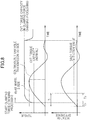
- FIG. 8 explains timing for executing the clamping force changing processing.
- a back torque input into the rear wheel 3 a back torque transmitted via the cam damper 9 to the continuously variable transmission 30, and the torque capacity of the continuously variable transmission 30 (CVT torque capacity)
- CVT torque capacity the torque capacity of the continuously variable transmission 30
- change as time passes in the difference in the rotation speed between the secondary shaft 34 and the intermediate shaft 37 corresponds to a change as time passes in a back torque transmitted via the cam damper 9 to the continuously variable transmission 30.
- Time T1 indicates a period of time elapsed until the magnitude of a back torque transmitted to the continuously variable transmission 30 becomes the same as the torque capacity of the continuously variable transmission 30 in the normal processing after the back torque is input into the rear wheel 3.
- Time T2 indicates a period of time elapsed, after input of a back torque into the rear wheel 3 until detection of back torque occurrence.
- Time T3 indicates a period of time elapsed after start of the clamping force changing processing until completion of increase of the torque capacity of the continuously variable transmission 30.
- a back torque detection value is set such that time T2 has a value equal to or smaller than a value obtained by subtracting time T3 from time T1.
- the cam damper 9 for delaying timing for transmission of a back torque input into the rear wheel 3 to the continuously variable transmission 30 it is possible to increase the clamping forces of the first pulley 31 and the second pulley 32 by the time when a back torque is transmitted to the continuously variable transmission 30. Further, as input of a back torque is detected based on the state of the cam damper 9, it is possible to increase or decrease the clamping forces of the first pulley 31 and the second pulley 32 in accordance with a time for transmission of a back torque to the continuously variable transmission 30.
- whether or not a back torque has been input into the rear wheel 3 is determined based on whether or not a difference equal to or larger than a predetermined difference is caused between the rotation speed of the secondary shaft 34 and that of the intermediate shaft 37, shown in FIG. 3 .
- This enables detection of a displacement in the circumferential direction of the convex portion 94c of the second shaft mounted member 94 inserted in the concave portion 92a of the first shaft mounted member 92.
- whether or not a back torque has been input into the rear wheel 3 is determined based on whether or not a phase difference equal to or larger than a predetermined phase difference is caused between the rotation of the secondary shaft 34 and that of the intermediate shaft 37, shown in FIG. 3 .
- This enables detection of a displacement in the circumferential direction of the convex portion 94c of the second shaft mounted member 94 inserted in the concave portion 92a of the first shaft mounted member 92.
- whether or not a back torque has been input into the rear wheel 3 is determined based on whether or not the second shaft mounted member 94 included in the cam damper 9 shown in FIG. 3 has been moved in the axial direction by an amount larger than a predetermined amount. This enables detection of a displacement in the axial direction of the second shaft mounted member 94.
- the rotation speed of the intermediate shaft 37 which is used in determination as to whether or not a back torque has been input into the rear wheel 3, is calculated based on a signal output from the rear wheel rotation sensor 3a for determining the rotation speed of the rear wheel 3.
- a rear wheel rotation sensor 3a is generally equipped to the two-wheeled motor vehicle 1
- use of the rotation speed of the rear wheel 3 obtained from a signal output from the rear wheel rotation sensor 3a eliminates the need of separate provision of a sensor for determining the rotation speed of the intermediate shaft 37.
- the rotation speed of the intermediate shaft 37 which is used in determination as to whether or not a back torque has been input into the rear wheel 3, may be calculated based on a signal output from the rear wheel rotation sensor 101 included in the brake device 100.
- a rear wheel rotation sensor 101 is generally equipped to the brake device 100 for implementing the ABS, use of the rotation speed of the rear wheel 3 obtained from a signal output from the rear wheel rotation sensor 101 eliminates the need of separate provision of a sensor for determining the rotation speed of the intermediate shaft 37.
- the clamping force changing processing unit 42i increases the clamping forces of the first pulley 31 and the second pulley 32 such that the torque capacity of the continuously variable transmission 30 becomes higher than the torque capacity of the clutch 61.
- the clamping force changing processing unit 42i increases the clamping forces of the first pulley 31 and the second pulley 32 such that the torque capacity of the continuously variable transmission 30 becomes higher than the torque capacity of the cam damper 9.
- the clutch 61 made using a centrifugal clutch is used. This enables a simpler and smaller device structure in the size, compared to a technique utilizing an electronically-controlled clutch to prevent back torque transmission.
- hydraulic actuators are used as the first actuator 51a and the second actuator 52b for changing the transmission gear ratio of the continuously variable transmission 30 in the above embodiment, this is not limiting, and an actuator, such as a motor, may be employed.
- the elastic member 96 made using a coil spring is used as the cam damper 9, this is not limiting, and a cam damper including a conical spring may be used. Further, a cam damper is not limiting, and any torque interfering mechanism for delaying timing for transmission of a back torque input into the rear wheel 3 to the continuously variable transmission 30 by an action of an elastic member is applicable.
Landscapes
- Engineering & Computer Science (AREA)
- General Engineering & Computer Science (AREA)
- Mechanical Engineering (AREA)
- Control Of Transmission Device (AREA)
Claims (12)
- Ein Fahrzeug (1), das folgende Merkmale aufweist:einen Motor (20);ein kontinuierlich veränderliches Getriebe (30) zum Empfangen eines Drehmoments von dem Motor (20), das eine stationäre Scheibe (31 b, 32b), eine bewegbare Scheibe (31 a, 32a), die gegenüber der stationären Scheibe (31 b, 32b) vorgesehen ist und in der Lage ist, sich relativ zu derselben zu bewegen, und eine Betätigungsvorrichtung (51 a, 52a) zum Bewegen der bewegbaren Scheibe (31 a, 32a) umfasst;eine Steuervorrichtung (10) zum Antreiben der Betätigungseinrichtung (51a, 52a), um eine Klemmkraft zu steuern, die eine Kraft zum Klemmen eines Riemens (33) durch die stationäre Scheibe (31 b, 32b) und die bewegbare Scheibe (31 a, 32a) darstellt;ein Antriebsrad (3) zum Empfangen eines Drehmoments von dem kontinuierlich veränderlichen Getriebe (30); undeinen Drehmomentdämpfungsmechanismus (9), der auf einem Drehmomentübertragungsweg zwischen dem kontinuierlich veränderlichen Getriebe (30) und dem Antriebsrad (3) vorgesehen ist, zum Verzögern einer Zeitsteuerung für eine Übertragung einer Drehmomentfluktuation mit einer negativen Winkelbeschleunigung, die an einem nachgeschalteten Drehmomentübertragungsbauglied (37) auftritt, das nachgeschaltet zu dem Drehmomentdämpfungsmechanismus (9) positioniert ist, zu einem vorgeschalteten Drehmomentübertragungsbauglied (34), das vorgeschaltet zu dem Drehmomentdämpfungsmechanismus (9) positioniert ist, indem eine Drehrichtung des nachgeschalteten Drehmomentübertragungsbauglieds (37) als positiv definiert wird,dadurch gekennzeichnet, dass die Steuervorrichtung (10) folgende Merkmale umfasst:eine Zustandsinformationenerhaltungseinheit (46) zum Erhalten, als Informationen, die einen Zustand des Drehmomentdämpfungsmechanismus (9) beschreiben, vonInformationen über die Drehung des vorgeschalteten Drehmomentübertragungsbauglieds (34) und Informationen über die Drehung des nachgeschalteten Drehmomentübertragungsbauglieds (37), oderPositionsinformationen über ein Verschiebungsbauglied (94) in dem Drehmomentdämpfungsmechanismus (9), das sich gemäß einer Beziehung zwischen einem Drehmoment des vorgeschalteten Drehmomentübertragungsbauglieds (34) und einem Drehmoment des nachgeschalteten Drehmomentübertragungsbauglieds (37) bewegt, undeine Klemmkraftänderungsverarbeitungseinheit (42i) zum Erhöhen der Klemmkraft, wenn ein Auftreten einer Drehmomentfluktuation an dem nachgeschalteten Drehmomentübertragungsbauglied (37) basierend auf dem Zustand des Drehmomentdämpfungsmechanismus (9) erfasst wird.
- Das Fahrzeug (1) gemäß Anspruch 1, bei dem
die Klemmkraftänderungsverarbeitungseinheit (42i) die Klemmkraft erhöht, wenn eine Phasendifferenz gleich wie oder größer als eine vorbestimmte Phasendifferenz zwischen der Drehung des vorgeschalteten Drehmomentübertragungsbauglieds (34) und der Drehung des nachgeschalteten Drehmomentübertragungsbauglieds (37) verursacht wird. - Das Fahrzeug (1) gemäß Anspruch 1, bei dem
die Klemmkraftänderungsverarbeitungseinheit (42i) die Klemmkraft erhöht, wenn eine Differenz gleich wie oder größer als eine vorbestimmte Differenz zwischen einer Drehgeschwindigkeit des vorgeschalteten Drehmomentübertragungsbauglieds (34) und einer Drehgeschwindigkeit des nachgeschalteten Drehmomentübertragungsbauglieds (37) verursacht wird. - Das Fahrzeug (1) gemäß Anspruch 1, bei dem
die Klemmkraftänderungsverarbeitungseinheit (42i) die Klemmkraft basierend auf einer Position des Verschiebungsbauglieds (94) verändert. - Das Fahrzeug (1) gemäß Anspruch 2 oder 3, das ferner folgende Merkmale aufweist:eine Bremsvorrichtung (100) mit einer Dreherfassungseinheit (101) zum Erfassen einer Drehung des Antriebsrads (3) zum Bremsen des Antriebsrads (3) basierend auf einer Drehgeschwindigkeit des Antriebsrads (3), wobeidie Zustandsinformationserhaltungseinheit (46) die Informationen über die Drehung des nachgeschalteten Drehmomentübertragungsbauglieds (37) von der Dreherfassungseinheit (101) erhält.
- Das Fahrzeug (1) gemäß Anspruch 2 oder 3, bei dem die Zustandsinformationserhaltungseinheit (46) die Informationen über die Drehung des nachgeschalteten Drehmomentübertragungsbauglieds (37) von einer Dreherfassungseinheit (101) zum Erfassen einer Drehung des Antriebsrads (3) erhält.
- Das Fahrzeug (1) gemäß Anspruch 1, das ferner eine Kupplung (61) aufweist, die auf dem Drehmomentübertragungsweg vorgesehen ist, wobei die Klemmkraftänderungsverarbeitungseinheit (42i) die Klemmkraft erhöht, sodass eine Drehmomentkapazität des kontinuierlich veränderlichen Getriebes (30) höher wird als eine Drehmomentkapazität der Kupplung (61).
- Das Fahrzeug (1) gemäß Anspruch 1, bei dem die Klemmkraftänderungsverarbeitungseinheit (42i) die Klemmkraft erhöht, sodass eine Drehmomentkapazität des kontinuierlich veränderlichen Getriebes (30) höher wird als eine Drehmomentkapazität des Drehmomentdämpfungsmechanismus (9).
- Das Fahrzeug (1) gemäß Anspruch 1, bei dem
der Drehmomentdämpfungsmechanismus (9) ein Nockendämpfer ist, der folgende Merkmale umfasst:ein erstes Bauglied (92), das mit dem vorgeschalteten Drehmomentübertragungsbauglied (34) verbunden ist,ein zweites Bauglied (94), das mit dem nachgeschalteten Drehmomentübertragungsbauglied (37) verbunden ist, undein elastisches Bauglied (96) zum Drücken eines konvexen Abschnitts (94c), der entweder auf dem ersten Bauglied (92) oder dem zweiten Bauglied (94) gebildet ist, zu einer Nockenoberfläche (92c) in einem konkaven Abschnitt (92a), der auf dem anderen gebildet ist. - Das Fahrzeug (1) gemäß Anspruch 1, das ferner eine Fliehkraftkupplung (61) aufweist, die auf dem Drehmomentübertragungsweg vorgesehen ist.
- Das Fahrzeug (1) gemäß Anspruch 1, bei dem der Riemen (33) des kontinuierlich veränderlichen Getriebes (30) ein Metallriemen ist.
- Ein Verfahren zum Steuern eines Fahrzeugs (1), das folgende Merkmale umfasst:einen Motor (20),ein kontinuierlich veränderliches Getriebe (30) zum Empfangen eines Drehmoments von dem Motor (20), das eine stationäre Scheibe (31 b, 32b), eine bewegbare Scheibe (31 a, 32a), die gegenüber der stationären Scheibe (31 b, 32b) vorgesehen ist und in der Lage ist, sich relativ zu derselben zu bewegen, und eine Betätigungsvorrichtung (51 a, 52a) zum Bewegen der bewegbaren Scheibe (31 a, 32a) umfasst;eine Steuervorrichtung (10) zum Antreiben der Betätigungseinrichtung (51a, 52a), um eine Klemmkraft zu steuern, die eine Kraft zum Klemmen eines Riemens (33) durch die stationäre Scheibe (31 b, 32b) und die bewegbare Scheibe (31 a, 32a) darstellt;ein Antriebsrad (3) zum Empfangen eines Drehmoments von dem kontinuierlich veränderlichen Getriebe (30); undeinen Drehmomentdämpfungsmechanismus (9), der auf einem Drehmomentübertragungsweg zwischen dem kontinuierlich veränderlichen Getriebe (30) und dem Antriebsrad (3) vorgesehen ist, zum Verzögern einer Zeitsteuerung für eine Übertragung einer Drehmomentfluktuation mit einer negativen Winkelbeschleunigung, die an einem nachgeschalteten Drehmomentübertragungsbauglied (37) auftritt, das nachgeschaltet zu dem Drehmomentdämpfungsmechanismus (9) positioniert ist, zu einem vorgeschalteten Drehmomentübertragungsbauglied (34), das vorgeschaltet zu dem Drehmomentdämpfungsmechanismus (9) positioniert ist, indem eine Drehrichtung des nachgeschalteten Drehmomentübertragungsbauglieds (37) als positiv definiert wird,dadurch gekennzeichnet, dass das Verfahren folgende Schritte umfasst:Erhalten, als Informationen, die einen Zustand des Drehmomentdämpfungsmechanismus (9) beschreiben, vonInformationen über die Drehung des vorgeschalteten Drehmomentübertragungsbauglieds (34) und Informationen über die Drehung des nachgeschalteten Drehmomentübertragungsbauglieds (37), oderPositionsinformationen über ein Verschiebungsbauglied (94) in dem Drehmomentdämpfungsmechanismus (9), das sich gemäß einer Beziehung zwischen einem Drehmoment des vorgeschalteten Drehmomentübertragungsbauglieds (34) und einem Drehmoment des nachgeschalteten Drehmomentübertragungsbauglieds (37) bewegt, undErhöhen der Klemmkraft, wenn ein Auftreten einer Drehmomentfluktuation an dem nachgeschalteten Drehmomentübertragungsbauglied (37) basierend auf dem Zustand des Drehmomentdämpfungsmechanismus (9) erfasst wird.
Applications Claiming Priority (2)
| Application Number | Priority Date | Filing Date | Title |
|---|---|---|---|
| JP2009292220 | 2009-12-24 | ||
| PCT/JP2010/068677 WO2011077823A1 (ja) | 2009-12-24 | 2010-10-22 | 車両及びその制御方法 |
Publications (3)
| Publication Number | Publication Date |
|---|---|
| EP2518372A1 EP2518372A1 (de) | 2012-10-31 |
| EP2518372A4 EP2518372A4 (de) | 2015-07-01 |
| EP2518372B1 true EP2518372B1 (de) | 2017-01-04 |
Family
ID=44195368
Family Applications (1)
| Application Number | Title | Priority Date | Filing Date |
|---|---|---|---|
| EP10839060.0A Not-in-force EP2518372B1 (de) | 2009-12-24 | 2010-10-22 | Fahrzeug und steuerungsverfahren dafür |
Country Status (4)
| Country | Link |
|---|---|
| US (1) | US8753248B2 (de) |
| EP (1) | EP2518372B1 (de) |
| JP (1) | JP5685200B2 (de) |
| WO (1) | WO2011077823A1 (de) |
Families Citing this family (4)
| Publication number | Priority date | Publication date | Assignee | Title |
|---|---|---|---|---|
| CN107218362B (zh) * | 2017-07-13 | 2019-12-24 | 桐乡市常新农机专业合作社 | 一种用于纺织厂机床轴承的传动装置 |
| US10641391B2 (en) * | 2018-04-23 | 2020-05-05 | GM Global Technology Operations LLC | System and method for CVT clamp control based on oncoming conditions in a vehicle propulsion system |
| WO2020040183A1 (ja) * | 2018-08-22 | 2020-02-27 | ヤマハ発動機株式会社 | リーン車両 |
| EP3994375B1 (de) * | 2019-07-01 | 2024-12-18 | TEAM Industries, Inc. | Stufenlos schaltbares getriebe mit einheitlicher klemmenbetätigung |
Family Cites Families (15)
| Publication number | Priority date | Publication date | Assignee | Title |
|---|---|---|---|---|
| JPS6192332A (ja) | 1984-10-12 | 1986-05-10 | Kawasaki Heavy Ind Ltd | 動力伝達機構の緩衝装置 |
| JPS6228524A (ja) | 1985-07-31 | 1987-02-06 | Suzuki Motor Co Ltd | カムダンパ |
| JPH0674839B2 (ja) * | 1985-11-29 | 1994-09-21 | 株式会社豊田中央研究所 | 無段変速機用油圧制御装置 |
| JPS6346931A (ja) | 1987-06-11 | 1988-02-27 | Nissan Motor Co Ltd | 無段変速機の変速比制御方法 |
| JPH0763628A (ja) | 1993-08-31 | 1995-03-10 | Ntn Corp | ドライブシャフト及びその軸トルク測定方法 |
| US6547692B1 (en) * | 1999-06-12 | 2003-04-15 | Robert Bosch Gmbh | System for adjusting the tension of the continuous belt component of a CVT |
| US6290620B1 (en) * | 1999-06-25 | 2001-09-18 | Hamilton Sundstrand Corporation | Continuously variable transmission with control arrangement and method for reducing impact of shock load |
| US6634982B2 (en) * | 1999-12-24 | 2003-10-21 | Aisin Aw Co., Ltd. | Automatic speed changer controller, automatic speed changer control method, and recording medium having program for method recorded thereon |
| JP2003269591A (ja) | 2002-03-14 | 2003-09-25 | Toyota Motor Corp | 路面状態検出装置および無段変速機の制御装置 |
| CN100394082C (zh) | 2003-01-29 | 2008-06-11 | 本田技研工业株式会社 | 车辆控制系统 |
| JP3892403B2 (ja) | 2003-01-29 | 2007-03-14 | 本田技研工業株式会社 | 車両の制御装置 |
| JP4151607B2 (ja) * | 2004-05-06 | 2008-09-17 | トヨタ自動車株式会社 | ベルト式無段変速機 |
| US7739019B2 (en) * | 2004-12-20 | 2010-06-15 | Gm Global Technology Operations, Inc. | Rough road detection |
| JP5048952B2 (ja) | 2006-02-06 | 2012-10-17 | 富士重工業株式会社 | 車両用制御装置 |
| JP2008286594A (ja) | 2007-05-16 | 2008-11-27 | Jtekt Corp | 車両用トルク伝達装置 |
-
2010
- 2010-10-22 US US13/518,399 patent/US8753248B2/en not_active Expired - Fee Related
- 2010-10-22 WO PCT/JP2010/068677 patent/WO2011077823A1/ja not_active Ceased
- 2010-10-22 JP JP2011547379A patent/JP5685200B2/ja active Active
- 2010-10-22 EP EP10839060.0A patent/EP2518372B1/de not_active Not-in-force
Non-Patent Citations (1)
| Title |
|---|
| None * |
Also Published As
| Publication number | Publication date |
|---|---|
| WO2011077823A1 (ja) | 2011-06-30 |
| JPWO2011077823A1 (ja) | 2013-05-02 |
| EP2518372A4 (de) | 2015-07-01 |
| US8753248B2 (en) | 2014-06-17 |
| EP2518372A1 (de) | 2012-10-31 |
| US20120264566A1 (en) | 2012-10-18 |
| JP5685200B2 (ja) | 2015-03-18 |
Similar Documents
| Publication | Publication Date | Title |
|---|---|---|
| US8337363B2 (en) | Gear change control device, straddle-type vehicle, and gear change control method | |
| US7445107B2 (en) | Hydraulic clutch control system and method | |
| CA2874520C (en) | Shift control device for automatic transmission | |
| EP2557012A1 (de) | Steuervorrichtung für ein fahrzeug | |
| JP6092791B2 (ja) | 無段変速機の変速制御装置 | |
| EP2602463A1 (de) | Fahrzeug und antriebssteuervorrichtung für ein fahrzeug | |
| EP2518372B1 (de) | Fahrzeug und steuerungsverfahren dafür | |
| EP3054197B1 (de) | Steuerungsvorrichtung für einen stufenschaltgetriebemechanismus und system | |
| JP4897639B2 (ja) | 無段変速機の制御装置 | |
| US8844401B2 (en) | Accelerator pedal depression force control device | |
| EP2913504A1 (de) | Antriebsvorrichtung für ein fahrzeug | |
| US8360190B2 (en) | Two-wheeled motor vehicle | |
| JP5865484B2 (ja) | 車両の動力伝達機構の制御装置 | |
| US10252719B2 (en) | Control device for continuously variable transmission | |
| JP5708185B2 (ja) | 車両制御装置 | |
| JP7448430B2 (ja) | 惰性走行制御装置 | |
| KR101293315B1 (ko) | 타력 주행 시 라인압 제어가 가능한 무단변속기 및 그 라인압 제어방법 | |
| JP6106485B2 (ja) | 無段変速機の制御装置 | |
| JP2006046517A (ja) | 無段変速機の制御装置 | |
| JP6190759B2 (ja) | 車両の制御装置 | |
| JP2010265918A (ja) | 無段変速機の制御装置および制御方法 | |
| JP6205617B2 (ja) | 自動変速機の制御装置 | |
| JP2015113904A (ja) | 油圧制御装置 | |
| JP2008208828A (ja) | 車両、その制御装置および制御方法、並びにアイドルスピードコントロール装置の異常検出装置およびアイドルスピードコントロール装置の異常検出方法 | |
| JP2014169749A (ja) | 車両の動力伝達機構の制御装置 |
Legal Events
| Date | Code | Title | Description |
|---|---|---|---|
| PUAI | Public reference made under article 153(3) epc to a published international application that has entered the european phase |
Free format text: ORIGINAL CODE: 0009012 |
|
| 17P | Request for examination filed |
Effective date: 20120622 |
|
| AK | Designated contracting states |
Kind code of ref document: A1 Designated state(s): AL AT BE BG CH CY CZ DE DK EE ES FI FR GB GR HR HU IE IS IT LI LT LU LV MC MK MT NL NO PL PT RO RS SE SI SK SM TR |
|
| DAX | Request for extension of the european patent (deleted) | ||
| RA4 | Supplementary search report drawn up and despatched (corrected) |
Effective date: 20150601 |
|
| RIC1 | Information provided on ipc code assigned before grant |
Ipc: F16H 59/68 20060101ALI20150526BHEP Ipc: F16H 61/12 20100101AFI20150526BHEP |
|
| GRAP | Despatch of communication of intention to grant a patent |
Free format text: ORIGINAL CODE: EPIDOSNIGR1 |
|
| INTG | Intention to grant announced |
Effective date: 20160720 |
|
| GRAS | Grant fee paid |
Free format text: ORIGINAL CODE: EPIDOSNIGR3 |
|
| GRAA | (expected) grant |
Free format text: ORIGINAL CODE: 0009210 |
|
| AK | Designated contracting states |
Kind code of ref document: B1 Designated state(s): AL AT BE BG CH CY CZ DE DK EE ES FI FR GB GR HR HU IE IS IT LI LT LU LV MC MK MT NL NO PL PT RO RS SE SI SK SM TR |
|
| REG | Reference to a national code |
Ref country code: GB Ref legal event code: FG4D |
|
| REG | Reference to a national code |
Ref country code: CH Ref legal event code: EP |
|
| REG | Reference to a national code |
Ref country code: AT Ref legal event code: REF Ref document number: 859572 Country of ref document: AT Kind code of ref document: T Effective date: 20170115 |
|
| REG | Reference to a national code |
Ref country code: IE Ref legal event code: FG4D |
|
| REG | Reference to a national code |
Ref country code: DE Ref legal event code: R096 Ref document number: 602010039421 Country of ref document: DE |
|
| REG | Reference to a national code |
Ref country code: LT Ref legal event code: MG4D Ref country code: NL Ref legal event code: MP Effective date: 20170104 |
|
| REG | Reference to a national code |
Ref country code: AT Ref legal event code: MK05 Ref document number: 859572 Country of ref document: AT Kind code of ref document: T Effective date: 20170104 |
|
| PG25 | Lapsed in a contracting state [announced via postgrant information from national office to epo] |
Ref country code: NL Free format text: LAPSE BECAUSE OF FAILURE TO SUBMIT A TRANSLATION OF THE DESCRIPTION OR TO PAY THE FEE WITHIN THE PRESCRIBED TIME-LIMIT Effective date: 20170104 |
|
| PG25 | Lapsed in a contracting state [announced via postgrant information from national office to epo] |
Ref country code: HR Free format text: LAPSE BECAUSE OF FAILURE TO SUBMIT A TRANSLATION OF THE DESCRIPTION OR TO PAY THE FEE WITHIN THE PRESCRIBED TIME-LIMIT Effective date: 20170104 Ref country code: LT Free format text: LAPSE BECAUSE OF FAILURE TO SUBMIT A TRANSLATION OF THE DESCRIPTION OR TO PAY THE FEE WITHIN THE PRESCRIBED TIME-LIMIT Effective date: 20170104 Ref country code: NO Free format text: LAPSE BECAUSE OF FAILURE TO SUBMIT A TRANSLATION OF THE DESCRIPTION OR TO PAY THE FEE WITHIN THE PRESCRIBED TIME-LIMIT Effective date: 20170404 Ref country code: GR Free format text: LAPSE BECAUSE OF FAILURE TO SUBMIT A TRANSLATION OF THE DESCRIPTION OR TO PAY THE FEE WITHIN THE PRESCRIBED TIME-LIMIT Effective date: 20170405 Ref country code: IS Free format text: LAPSE BECAUSE OF FAILURE TO SUBMIT A TRANSLATION OF THE DESCRIPTION OR TO PAY THE FEE WITHIN THE PRESCRIBED TIME-LIMIT Effective date: 20170504 Ref country code: FI Free format text: LAPSE BECAUSE OF FAILURE TO SUBMIT A TRANSLATION OF THE DESCRIPTION OR TO PAY THE FEE WITHIN THE PRESCRIBED TIME-LIMIT Effective date: 20170104 |
|
| PG25 | Lapsed in a contracting state [announced via postgrant information from national office to epo] |
Ref country code: ES Free format text: LAPSE BECAUSE OF FAILURE TO SUBMIT A TRANSLATION OF THE DESCRIPTION OR TO PAY THE FEE WITHIN THE PRESCRIBED TIME-LIMIT Effective date: 20170104 Ref country code: SE Free format text: LAPSE BECAUSE OF FAILURE TO SUBMIT A TRANSLATION OF THE DESCRIPTION OR TO PAY THE FEE WITHIN THE PRESCRIBED TIME-LIMIT Effective date: 20170104 Ref country code: PT Free format text: LAPSE BECAUSE OF FAILURE TO SUBMIT A TRANSLATION OF THE DESCRIPTION OR TO PAY THE FEE WITHIN THE PRESCRIBED TIME-LIMIT Effective date: 20170504 Ref country code: AT Free format text: LAPSE BECAUSE OF FAILURE TO SUBMIT A TRANSLATION OF THE DESCRIPTION OR TO PAY THE FEE WITHIN THE PRESCRIBED TIME-LIMIT Effective date: 20170104 Ref country code: PL Free format text: LAPSE BECAUSE OF FAILURE TO SUBMIT A TRANSLATION OF THE DESCRIPTION OR TO PAY THE FEE WITHIN THE PRESCRIBED TIME-LIMIT Effective date: 20170104 Ref country code: RS Free format text: LAPSE BECAUSE OF FAILURE TO SUBMIT A TRANSLATION OF THE DESCRIPTION OR TO PAY THE FEE WITHIN THE PRESCRIBED TIME-LIMIT Effective date: 20170104 Ref country code: LV Free format text: LAPSE BECAUSE OF FAILURE TO SUBMIT A TRANSLATION OF THE DESCRIPTION OR TO PAY THE FEE WITHIN THE PRESCRIBED TIME-LIMIT Effective date: 20170104 Ref country code: BG Free format text: LAPSE BECAUSE OF FAILURE TO SUBMIT A TRANSLATION OF THE DESCRIPTION OR TO PAY THE FEE WITHIN THE PRESCRIBED TIME-LIMIT Effective date: 20170404 |
|
| REG | Reference to a national code |
Ref country code: DE Ref legal event code: R097 Ref document number: 602010039421 Country of ref document: DE |
|
| PG25 | Lapsed in a contracting state [announced via postgrant information from national office to epo] |
Ref country code: SK Free format text: LAPSE BECAUSE OF FAILURE TO SUBMIT A TRANSLATION OF THE DESCRIPTION OR TO PAY THE FEE WITHIN THE PRESCRIBED TIME-LIMIT Effective date: 20170104 Ref country code: EE Free format text: LAPSE BECAUSE OF FAILURE TO SUBMIT A TRANSLATION OF THE DESCRIPTION OR TO PAY THE FEE WITHIN THE PRESCRIBED TIME-LIMIT Effective date: 20170104 Ref country code: CZ Free format text: LAPSE BECAUSE OF FAILURE TO SUBMIT A TRANSLATION OF THE DESCRIPTION OR TO PAY THE FEE WITHIN THE PRESCRIBED TIME-LIMIT Effective date: 20170104 Ref country code: RO Free format text: LAPSE BECAUSE OF FAILURE TO SUBMIT A TRANSLATION OF THE DESCRIPTION OR TO PAY THE FEE WITHIN THE PRESCRIBED TIME-LIMIT Effective date: 20170104 Ref country code: IT Free format text: LAPSE BECAUSE OF FAILURE TO SUBMIT A TRANSLATION OF THE DESCRIPTION OR TO PAY THE FEE WITHIN THE PRESCRIBED TIME-LIMIT Effective date: 20170104 |
|
| PLBE | No opposition filed within time limit |
Free format text: ORIGINAL CODE: 0009261 |
|
| STAA | Information on the status of an ep patent application or granted ep patent |
Free format text: STATUS: NO OPPOSITION FILED WITHIN TIME LIMIT |
|
| PG25 | Lapsed in a contracting state [announced via postgrant information from national office to epo] |
Ref country code: DK Free format text: LAPSE BECAUSE OF FAILURE TO SUBMIT A TRANSLATION OF THE DESCRIPTION OR TO PAY THE FEE WITHIN THE PRESCRIBED TIME-LIMIT Effective date: 20170104 Ref country code: SM Free format text: LAPSE BECAUSE OF FAILURE TO SUBMIT A TRANSLATION OF THE DESCRIPTION OR TO PAY THE FEE WITHIN THE PRESCRIBED TIME-LIMIT Effective date: 20170104 |
|
| 26N | No opposition filed |
Effective date: 20171005 |
|
| PG25 | Lapsed in a contracting state [announced via postgrant information from national office to epo] |
Ref country code: SI Free format text: LAPSE BECAUSE OF FAILURE TO SUBMIT A TRANSLATION OF THE DESCRIPTION OR TO PAY THE FEE WITHIN THE PRESCRIBED TIME-LIMIT Effective date: 20170104 |
|
| PG25 | Lapsed in a contracting state [announced via postgrant information from national office to epo] |
Ref country code: MC Free format text: LAPSE BECAUSE OF FAILURE TO SUBMIT A TRANSLATION OF THE DESCRIPTION OR TO PAY THE FEE WITHIN THE PRESCRIBED TIME-LIMIT Effective date: 20170104 |
|
| REG | Reference to a national code |
Ref country code: CH Ref legal event code: PL |
|
| REG | Reference to a national code |
Ref country code: IE Ref legal event code: MM4A |
|
| REG | Reference to a national code |
Ref country code: FR Ref legal event code: ST Effective date: 20180629 |
|
| PG25 | Lapsed in a contracting state [announced via postgrant information from national office to epo] |
Ref country code: LU Free format text: LAPSE BECAUSE OF NON-PAYMENT OF DUE FEES Effective date: 20171022 Ref country code: LI Free format text: LAPSE BECAUSE OF NON-PAYMENT OF DUE FEES Effective date: 20171031 Ref country code: CH Free format text: LAPSE BECAUSE OF NON-PAYMENT OF DUE FEES Effective date: 20171031 |
|
| REG | Reference to a national code |
Ref country code: BE Ref legal event code: MM Effective date: 20171031 |
|
| PG25 | Lapsed in a contracting state [announced via postgrant information from national office to epo] |
Ref country code: BE Free format text: LAPSE BECAUSE OF NON-PAYMENT OF DUE FEES Effective date: 20171031 Ref country code: FR Free format text: LAPSE BECAUSE OF NON-PAYMENT OF DUE FEES Effective date: 20171031 |
|
| PG25 | Lapsed in a contracting state [announced via postgrant information from national office to epo] |
Ref country code: MT Free format text: LAPSE BECAUSE OF NON-PAYMENT OF DUE FEES Effective date: 20171022 |
|
| PG25 | Lapsed in a contracting state [announced via postgrant information from national office to epo] |
Ref country code: IE Free format text: LAPSE BECAUSE OF NON-PAYMENT OF DUE FEES Effective date: 20171022 |
|
| PGFP | Annual fee paid to national office [announced via postgrant information from national office to epo] |
Ref country code: DE Payment date: 20181019 Year of fee payment: 9 |
|
| PGFP | Annual fee paid to national office [announced via postgrant information from national office to epo] |
Ref country code: GB Payment date: 20181019 Year of fee payment: 9 |
|
| PG25 | Lapsed in a contracting state [announced via postgrant information from national office to epo] |
Ref country code: HU Free format text: LAPSE BECAUSE OF FAILURE TO SUBMIT A TRANSLATION OF THE DESCRIPTION OR TO PAY THE FEE WITHIN THE PRESCRIBED TIME-LIMIT; INVALID AB INITIO Effective date: 20101022 |
|
| PG25 | Lapsed in a contracting state [announced via postgrant information from national office to epo] |
Ref country code: CY Free format text: LAPSE BECAUSE OF NON-PAYMENT OF DUE FEES Effective date: 20170104 |
|
| PG25 | Lapsed in a contracting state [announced via postgrant information from national office to epo] |
Ref country code: MK Free format text: LAPSE BECAUSE OF FAILURE TO SUBMIT A TRANSLATION OF THE DESCRIPTION OR TO PAY THE FEE WITHIN THE PRESCRIBED TIME-LIMIT Effective date: 20170104 |
|
| PG25 | Lapsed in a contracting state [announced via postgrant information from national office to epo] |
Ref country code: TR Free format text: LAPSE BECAUSE OF FAILURE TO SUBMIT A TRANSLATION OF THE DESCRIPTION OR TO PAY THE FEE WITHIN THE PRESCRIBED TIME-LIMIT Effective date: 20170104 |
|
| REG | Reference to a national code |
Ref country code: DE Ref legal event code: R119 Ref document number: 602010039421 Country of ref document: DE |
|
| PG25 | Lapsed in a contracting state [announced via postgrant information from national office to epo] |
Ref country code: AL Free format text: LAPSE BECAUSE OF FAILURE TO SUBMIT A TRANSLATION OF THE DESCRIPTION OR TO PAY THE FEE WITHIN THE PRESCRIBED TIME-LIMIT Effective date: 20170104 Ref country code: DE Free format text: LAPSE BECAUSE OF NON-PAYMENT OF DUE FEES Effective date: 20200501 |
|
| GBPC | Gb: european patent ceased through non-payment of renewal fee |
Effective date: 20191022 |
|
| PG25 | Lapsed in a contracting state [announced via postgrant information from national office to epo] |
Ref country code: GB Free format text: LAPSE BECAUSE OF NON-PAYMENT OF DUE FEES Effective date: 20191022 |