EP3994375B1 - Stufenlos schaltbares getriebe mit einheitlicher klemmenbetätigung - Google Patents
Stufenlos schaltbares getriebe mit einheitlicher klemmenbetätigung Download PDFInfo
- Publication number
- EP3994375B1 EP3994375B1 EP20743516.5A EP20743516A EP3994375B1 EP 3994375 B1 EP3994375 B1 EP 3994375B1 EP 20743516 A EP20743516 A EP 20743516A EP 3994375 B1 EP3994375 B1 EP 3994375B1
- Authority
- EP
- European Patent Office
- Prior art keywords
- drive
- driven
- clutch
- cam
- torque
- Prior art date
- Legal status (The legal status is an assumption and is not a legal conclusion. Google has not performed a legal analysis and makes no representation as to the accuracy of the status listed.)
- Active
Links
Images






Classifications
-
- F—MECHANICAL ENGINEERING; LIGHTING; HEATING; WEAPONS; BLASTING
- F16—ENGINEERING ELEMENTS AND UNITS; GENERAL MEASURES FOR PRODUCING AND MAINTAINING EFFECTIVE FUNCTIONING OF MACHINES OR INSTALLATIONS; THERMAL INSULATION IN GENERAL
- F16H—GEARING
- F16H55/00—Elements with teeth or friction surfaces for conveying motion; Worms, pulleys or sheaves for gearing mechanisms
- F16H55/32—Friction members
- F16H55/52—Pulleys or friction discs of adjustable construction
- F16H55/56—Pulleys or friction discs of adjustable construction of which the bearing parts are relatively axially adjustable
-
- F—MECHANICAL ENGINEERING; LIGHTING; HEATING; WEAPONS; BLASTING
- F16—ENGINEERING ELEMENTS AND UNITS; GENERAL MEASURES FOR PRODUCING AND MAINTAINING EFFECTIVE FUNCTIONING OF MACHINES OR INSTALLATIONS; THERMAL INSULATION IN GENERAL
- F16H—GEARING
- F16H61/00—Control functions within control units of change-speed- or reversing-gearings for conveying rotary motion ; Control of exclusively fluid gearing, friction gearing, gearings with endless flexible members or other particular types of gearing
- F16H61/66—Control functions within control units of change-speed- or reversing-gearings for conveying rotary motion ; Control of exclusively fluid gearing, friction gearing, gearings with endless flexible members or other particular types of gearing specially adapted for continuously variable gearings
- F16H61/662—Control functions within control units of change-speed- or reversing-gearings for conveying rotary motion ; Control of exclusively fluid gearing, friction gearing, gearings with endless flexible members or other particular types of gearing specially adapted for continuously variable gearings with endless flexible members
- F16H61/6625—Control functions within control units of change-speed- or reversing-gearings for conveying rotary motion ; Control of exclusively fluid gearing, friction gearing, gearings with endless flexible members or other particular types of gearing specially adapted for continuously variable gearings with endless flexible members controlling shifting exclusively as a function of torque
-
- F—MECHANICAL ENGINEERING; LIGHTING; HEATING; WEAPONS; BLASTING
- F16—ENGINEERING ELEMENTS AND UNITS; GENERAL MEASURES FOR PRODUCING AND MAINTAINING EFFECTIVE FUNCTIONING OF MACHINES OR INSTALLATIONS; THERMAL INSULATION IN GENERAL
- F16H—GEARING
- F16H61/00—Control functions within control units of change-speed- or reversing-gearings for conveying rotary motion ; Control of exclusively fluid gearing, friction gearing, gearings with endless flexible members or other particular types of gearing
- F16H61/66—Control functions within control units of change-speed- or reversing-gearings for conveying rotary motion ; Control of exclusively fluid gearing, friction gearing, gearings with endless flexible members or other particular types of gearing specially adapted for continuously variable gearings
- F16H61/662—Control functions within control units of change-speed- or reversing-gearings for conveying rotary motion ; Control of exclusively fluid gearing, friction gearing, gearings with endless flexible members or other particular types of gearing specially adapted for continuously variable gearings with endless flexible members
- F16H61/66254—Control functions within control units of change-speed- or reversing-gearings for conveying rotary motion ; Control of exclusively fluid gearing, friction gearing, gearings with endless flexible members or other particular types of gearing specially adapted for continuously variable gearings with endless flexible members controlling of shifting being influenced by a signal derived from the engine and the main coupling
- F16H61/66268—Control functions within control units of change-speed- or reversing-gearings for conveying rotary motion ; Control of exclusively fluid gearing, friction gearing, gearings with endless flexible members or other particular types of gearing specially adapted for continuously variable gearings with endless flexible members controlling of shifting being influenced by a signal derived from the engine and the main coupling using purely mechanical sensing or control means
-
- F—MECHANICAL ENGINEERING; LIGHTING; HEATING; WEAPONS; BLASTING
- F16—ENGINEERING ELEMENTS AND UNITS; GENERAL MEASURES FOR PRODUCING AND MAINTAINING EFFECTIVE FUNCTIONING OF MACHINES OR INSTALLATIONS; THERMAL INSULATION IN GENERAL
- F16H—GEARING
- F16H61/00—Control functions within control units of change-speed- or reversing-gearings for conveying rotary motion ; Control of exclusively fluid gearing, friction gearing, gearings with endless flexible members or other particular types of gearing
- F16H61/66—Control functions within control units of change-speed- or reversing-gearings for conveying rotary motion ; Control of exclusively fluid gearing, friction gearing, gearings with endless flexible members or other particular types of gearing specially adapted for continuously variable gearings
- F16H61/662—Control functions within control units of change-speed- or reversing-gearings for conveying rotary motion ; Control of exclusively fluid gearing, friction gearing, gearings with endless flexible members or other particular types of gearing specially adapted for continuously variable gearings with endless flexible members
- F16H61/66272—Control functions within control units of change-speed- or reversing-gearings for conveying rotary motion ; Control of exclusively fluid gearing, friction gearing, gearings with endless flexible members or other particular types of gearing specially adapted for continuously variable gearings with endless flexible members characterised by means for controlling the torque transmitting capability of the gearing
-
- F—MECHANICAL ENGINEERING; LIGHTING; HEATING; WEAPONS; BLASTING
- F16—ENGINEERING ELEMENTS AND UNITS; GENERAL MEASURES FOR PRODUCING AND MAINTAINING EFFECTIVE FUNCTIONING OF MACHINES OR INSTALLATIONS; THERMAL INSULATION IN GENERAL
- F16H—GEARING
- F16H63/00—Control outputs from the control unit to change-speed- or reversing-gearings for conveying rotary motion or to other devices than the final output mechanism
- F16H63/02—Final output mechanisms therefor; Actuating means for the final output mechanisms
- F16H63/04—Final output mechanisms therefor; Actuating means for the final output mechanisms a single final output mechanism being moved by a single final actuating mechanism
- F16H63/06—Final output mechanisms therefor; Actuating means for the final output mechanisms a single final output mechanism being moved by a single final actuating mechanism the final output mechanism having an indefinite number of positions
- F16H63/062—Final output mechanisms therefor; Actuating means for the final output mechanisms a single final output mechanism being moved by a single final actuating mechanism the final output mechanism having an indefinite number of positions electric or electro-mechanical actuating means
-
- F—MECHANICAL ENGINEERING; LIGHTING; HEATING; WEAPONS; BLASTING
- F16—ENGINEERING ELEMENTS AND UNITS; GENERAL MEASURES FOR PRODUCING AND MAINTAINING EFFECTIVE FUNCTIONING OF MACHINES OR INSTALLATIONS; THERMAL INSULATION IN GENERAL
- F16H—GEARING
- F16H9/00—Gearings for conveying rotary motion with variable gear ratio, or for reversing rotary motion, by endless flexible members
- F16H9/02—Gearings for conveying rotary motion with variable gear ratio, or for reversing rotary motion, by endless flexible members without members having orbital motion
- F16H9/04—Gearings for conveying rotary motion with variable gear ratio, or for reversing rotary motion, by endless flexible members without members having orbital motion using belts, V-belts, or ropes
- F16H9/12—Gearings for conveying rotary motion with variable gear ratio, or for reversing rotary motion, by endless flexible members without members having orbital motion using belts, V-belts, or ropes engaging a pulley built-up out of relatively axially-adjustable parts in which the belt engages the opposite flanges of the pulley directly without interposed belt-supporting members
- F16H9/16—Gearings for conveying rotary motion with variable gear ratio, or for reversing rotary motion, by endless flexible members without members having orbital motion using belts, V-belts, or ropes engaging a pulley built-up out of relatively axially-adjustable parts in which the belt engages the opposite flanges of the pulley directly without interposed belt-supporting members using two pulleys, both built-up out of adjustable conical parts
- F16H9/18—Gearings for conveying rotary motion with variable gear ratio, or for reversing rotary motion, by endless flexible members without members having orbital motion using belts, V-belts, or ropes engaging a pulley built-up out of relatively axially-adjustable parts in which the belt engages the opposite flanges of the pulley directly without interposed belt-supporting members using two pulleys, both built-up out of adjustable conical parts only one flange of each pulley being adjustable
-
- F—MECHANICAL ENGINEERING; LIGHTING; HEATING; WEAPONS; BLASTING
- F16—ENGINEERING ELEMENTS AND UNITS; GENERAL MEASURES FOR PRODUCING AND MAINTAINING EFFECTIVE FUNCTIONING OF MACHINES OR INSTALLATIONS; THERMAL INSULATION IN GENERAL
- F16H—GEARING
- F16H61/00—Control functions within control units of change-speed- or reversing-gearings for conveying rotary motion ; Control of exclusively fluid gearing, friction gearing, gearings with endless flexible members or other particular types of gearing
- F16H61/66—Control functions within control units of change-speed- or reversing-gearings for conveying rotary motion ; Control of exclusively fluid gearing, friction gearing, gearings with endless flexible members or other particular types of gearing specially adapted for continuously variable gearings
- F16H61/662—Control functions within control units of change-speed- or reversing-gearings for conveying rotary motion ; Control of exclusively fluid gearing, friction gearing, gearings with endless flexible members or other particular types of gearing specially adapted for continuously variable gearings with endless flexible members
- F16H61/66272—Control functions within control units of change-speed- or reversing-gearings for conveying rotary motion ; Control of exclusively fluid gearing, friction gearing, gearings with endless flexible members or other particular types of gearing specially adapted for continuously variable gearings with endless flexible members characterised by means for controlling the torque transmitting capability of the gearing
- F16H2061/66277—Control functions within control units of change-speed- or reversing-gearings for conveying rotary motion ; Control of exclusively fluid gearing, friction gearing, gearings with endless flexible members or other particular types of gearing specially adapted for continuously variable gearings with endless flexible members characterised by means for controlling the torque transmitting capability of the gearing by optimising the clamping force exerted on the endless flexible member
Definitions
- the invention relates to the field of infinitely variable transmission systems.
- Continuously variable transmission (CVT) or infinitely variable transmission (IVT) systems for off road utility vehicles, on road vehicles, golf carts, snowmobiles, industrial implements, energy conversion/storage devices, etc. comprise a drive clutch (sheave) and a driven clutch (sheave) in which torque is communicated between the two by a flexible, endless loop member such as a belt.
- the drive clutch employs the use of an RPM sensitive (centrifugal) drive clutch that is operational communication with an engine and a torque sensitive driven clutch that is in operational communication with a transmission.
- FR 1 106 748 A discloses an infinitely variable transmission system comprising:a drive clutch including, a drive post configured to be coupled to a motor to transfer torque between the motor and the drive post, two movable drive sheave members mounted on the drive post, and a drive torque sensitive assembly configured to move the movable drive sheave members axially on the drive post based at least on torque applied to the drive torque sensitive assembly through the drive post; a driven clutch, the drive clutch and driven clutch configured to transfer torque and rotation between each other with an endless loop member of the transmission system, the driven clutch including, a driven post configured to be coupled to a drivetrain to transfer torque between the driven post and the drivetrain, two movable driven sheave members mounted on the driven post, and a driven torque sensitive assembly configured to move the movable driven sheave members axially on the driven post based at least on torque applied to the driven torque sensitive assembly through the endless loop member.
- US 6 743 129 B1 discloses a clutch with no relative rotational movement between the sheaves.
- US 2005/277502 discloses a clutch system for belted constant velocity transmission.
- a uniform clamp actuated shift infinitely variable transmission as defined by claim 1.
- a vehicle including the uniform clamp actuated shift infinitely variable transmission, as defined in claim 9. Additional features are set out in the dependent claims.
- Embodiments provide a CVT/IVT system that incorporates a torque sensitive assembly in both the drive clutch and the driven clutch. Further embodiments provide a sheave with a torque sensitive assembly and actuator arrangement.
- the UCAS IVT system includes a drive clutch and a driven clutch is provided.
- the drive clutch included a drive post, a movable drive sheave member, a fixed drive sheave member and a drive torque sensitive assembly.
- the drive post is configured to be coupled to a motor.
- the movable drive sheave member is mounted on the drive post.
- the fixed drive sheave member is mounted on the drive post.
- the drive torque sensitive assembly is configured to move the movable drive sheave member axially on the drive post in relation to the fixed drive sheave member based at least on torque applied to the drive torque sensitive assembly through the drive post.
- the drive clutch and driven clutch are configured to transfer torque and rotation between each other with an endless loop member of the transmission system.
- the driven clutch includes a driven post, a movable driven sheave member, a fixed driven sheave member and a driven torque sensitive assembly.
- the driven post is configured to be coupled to a drivetrain.
- the movable driven sheave member is mounted on the driven post.
- the fixed driven sheave member is mounted on the driven post.
- the driven torque sensitive assembly is configured to move the movable driven sheave member axially on the driven post in relation to the fixed driven sheave member based at least on torque applied to the driven torque sensitive assembly through the endless loop member.
- the driven torque sensitive assembly comprises a driven spider coupled to the driven post, the rotation of the driven spider being fixed to the rotation of the driven post.
- the driven spider includes at least one driven spider arm.
- a driven cam roller is rotatably coupled on each of the at least one driven spider arm.
- a driven cam is coupled to the movable driven sheave member, wherein the driven cam has at least one cutout portion forming driven cam profile surfaces.
- Each driven cam roller is positioned within a cutout portion of the at least one cutout portion, wherein each driven cam roller engages associated driven cam profile surfaces to transfer torque and rotation between the driven spider and driven cam.
- At least one actuator is coupled to one of the movable drive sheave member of the drive clutch and the movable driven sheave member of the driven clutch to selectively move the respective one of the movable drive sheave member and the movable driven sheave member independent of the respective drive torque sensitive assembly and driven torque sensitive assembly to achieve at least one of a uniform clamping of the endless loop member between the drive clutch and the driven clutch, and a ratio change across the UCAS IVT system.
- a vehicle having the uniform clamp actuated shift infinitely variable transmission (UCAS IVT) system is provided.
- the vehicle includes a motor, a drivetrain and the UCAS IVT system.
- the motor is used to generate engine torque and rotation.
- Embodiments provide a uniform clamp actuated shift infinitely variable transmission (UCAS IVT) system that implements torque elements in both the drive clutch and the driven clutch of the IVT.
- the UCAS IVT system provides a dual torque sensitive system that reduces/eliminates the requirement for an actuator to supply full belt clamp force necessary to transmit or couple torque/power between sheaves in an IVT system in certain situations.
- Advantages to this design includes the ability to use smaller actuators to selectively control the shifting of the IVT, a lower force requirement that allows the actuator to complete a shift sequence faster and less energy required to power the actuator.
- some embodiments of the UCAS IVT system are capable of sensing torque in both directions, driving (from a drive clutch to a driven clutch) and back driving (from the driven clutch to the drive clutch).
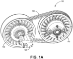
- Figures 1A through 3 illustrated one embodiment of a UCAS IVT system 100.
- Figure 1A illustrates a side perspective view UCAS IVT system 100
- Figure 1B illustrates an unassembled side view of the UCAS IVT system 100
- Figure 2 illustrates a cross-sectional side view of the UCAS IVT system.
- UCAS IVT system 100 in this example embodiment, includes a drive clutch 102 and a driven clutch 140 (or variable diameter pulleys or sheaves) that are rotationally coupled to transfer torque via an endless loop member 130.
- the endless loop member 130 may be, but is not limited to, a belt.
- Each sheave (or pulley) 102 and 140 includes its own torque sensitive assembly (200 and 240 respectively) discussed further in detail below.
- the drive clutch 102 is configured to be operationally coupled to a motor (such as motor 502 of Figure 11 ) while the driven clutch 140 is configured to be operationally coupled to a drivetrain (or the rest of a drivetrain) of a vehicle (such as vehicle 500 of Figure 11 ).
- the UCAS IVT system 100 further includes an actuator 120 that is operationally coupled to the drive clutch 102.
- the drive clutch 102 and driven clutch 140 each include a pair of fixed and movable sheave members discussed below that selectively vary the location of the endless loop member 130 in relation to a central axis 121 and 157 (illustrated in Figure 3 ) of the respective clutch 102 and 140 to selectively change the gear ratio of the respective clutch 102 and 140.
- the actuator 120 is used to control the gear ratio of the drive clutch 102 and driven clutch 140 independent of torque forces experienced by the drive clutch 102 and driven clutch 140 in embodiments.
- the drive clutch 102 includes a movable drive sheave member 101 and a fixed drive sheave member 103.
- a drive cam 104 (drive torque sensitive cam) is axially and rotationally fixed (coupled) to the moveable drive sheave member 101.
- the drive cam 104 is further axially and rotationally free about a central shaft 106 (or drive post 106) of the drive clutch 102.
- the fixed drive sheave member 103 is coupled to the drive post 106.
- the fixed drive sheave member 103 (stationary drive sheave member) is axially fixed but rotationally free about the drive post 106.
- the fixed drive sheave member 103 may be rotationally fixed to the drive post 106.
- tied drive rollers 109 that are mounted on a portion of the moveable drive sheave member 101 via mounting rod 107 and holding pin 111 arrangement are used.
- the tied drive rollers 109 are received in holding tracks 180 of the fixed drive sheave member 103.
- the holding tracks 180 associated with the fixed drive sheave member 103 may be straight, angled or curved.
- the movable drive sheave member 101 of the drive clutch 102 is slidably mounded on the drive post 106 while being rotationally free about the drive shaft 106.
- the actuator 120 is coupled to an actuator cup 117 in this example.
- the actuator 120 is configured to selectively push the drive cam 104 to move the movable drive sheave member 101 closer to the fixed drive sheave member 103 to engage the belt 130 (clamp down on the belt) as discussed below.
- the drive clutch 102 in this example embodiment further includes a bearing 124 that is positioned between an end portion of the drive post 106 and an opening in an end hub portion of the fixed drive sheave member 103.
- a retaining clip 123 positioned within a groove in the drive post retains in part the bearing 124 in a desired location on the drive post 106.
- Spacer members 125 and 126 are used to establish a pre-set minimum spacing between the fixed drive sheave member 103 and the movable drive sheave member to establish a sheave travel limit at a high ratio condition. The spacer members 125 and 126 are not needed in embodiments that maintain tension across the belt 130 at full low ratio.
- a drive torque sensitive assembly 200 of the drive clutch 102 includes the drive cam 104, a drive bias seat member 132, a drive bias member 116 and a drive spider 114.
- the drive bias seat member 132 is received within a hub portion of the movable drive sheave member 101 around the drive post 106 and is positioned to engage a first end of the drive bias member 116.
- the drive bias member 116 is a spring in this embodiment.
- a second end of the drive bias member 116 is positioned to engage a central ring portion of the drive spider 114.
- the drive bias member 116 provides a select bias force on the drive spider 114 away from an end of the hub portion the movable drive sheave member 101.
- the drive spider 114 includes arms that extend out in an opposite fashion from the central ring portion.
- Rotationally mounted on the arms of the drive spider 114 are drive cam rollers 112. They are mounted on the arms via C-clip 113 and washer 115 arrangement in this example embodiment.
- a retaining clip 133 at least in part prevents axial movement of the drive spider 114 along the drive post 106. Further, a spline arrangement between and inner surface of the central ring portion of the drive spider 114 and the drive post 105 locks rotation of the drive spider 114 with the rotation of the drive post 106.
- the drive cam 104 is coupled to the movable drive sheave member 101 via fasteners 134.
- the actuator cup 117 engages the drive cam 104 and is used by the actuator 120 to selectively move the movable drive sheave member 101 closer to the fixed drive sheave member 103.
- a bearing 135 is positioned around a portion of the actuator cup 117 and inner portion of the drive cam 104 in this embodiment to allow for rotation to occur between the actuator cup 117 and the drive cam 104.
- Retaining members 137 and 138 are used in part to retain a location of the bearing 136 in a desired position.
- the driven clutch 140 has a similar configuration as the drive clutch 102 including a movable drive sheave member 143 and a fixed driven sheave member 141 that are mounted on a driven post 146.
- the fixed driven sheave member 141 is axially fixed on the driven post 146 while the moveable driven sheave member 143 is able to axially move on the driven post 146.
- the movable driven sheave member 143 of the driven clutch 140 is slidably mounded on the driven post 146. In one embodiment the moveable driven sheave member 143 is also rotationally free about the driven post 146.
- the driven clutch 140 includes driven torque sensitive assembly 240 that includes a driven cam 144, a driven spider 150, a driven bias member 160 and a driven bias seat member 164.
- the driven cam 144 (torque sensitive cam) is axially and rotationally fixed (coupled) to the moveable driven sheave member 143 via fasteners 161.
- the driven cam 144 is further axially and rotationally free about the central driven post 146.
- the driven bias seat member 164 is received within a hub portion of the movable driven sheave member 143 around the driven post 146 and is positioned to engage a first end of the driven bias member 160.
- the driven bias member 160 is a spring in this embodiment.
- a second end of the driven bias member 160 is positioned to engage a central ring portion of the driven spider 150.
- the driven bias member 160 provides a select bias force on the driven spider 150 away from an end of the hub portion the movable driven sheave member 143.
- the driven spider 150 includes arms that extend in an opposite fashion from the central ring portion. Rotationally mounted on the arms of the driven spider 150 are driven cam rollers 152. They are mounted on the arms via C-clip 151 and washer 155 arrangement in this example embodiment.
- a retaining clip 162 at least in part prevents axial movement of the driven spider 150 along the driven post 146. Further, a spline arrangement between and inner surface of the central ring portion of the driven spider 150 and the driven post 146 locks rotation of the driven spider 150 with the rotation of the driven post 146.
- the fixed driven sheave member 141 of the driven clutch 140 is axially fixed to the central shaft 146 but rotationally free in an embodiment.
- the fixed driven sheave member 141 is uncoupled from the movable driven sheave member 143
- the fixed driven sheave member 141 is rotationally fixed to the driven post 146.
- tied rollers 166 that are mounted on a portion of the moveable driven sheave member 141 via mounting rod 167 and retaining pin 168 arrangement are used. The tied rollers 166 are received in respective holding tracks 169 of the fixed driven sheave members 141.
- a bearing 174 that mounted around an end portion of driven post 146 and is positioned to engage a portion of a hub portion of the fixed driven sheave member 141.
- Bearing 174 is axially fixed in a position on the driven post 146 by at least a retaining member 176.
- Spacing members 170 and 172 are used to establish a pre-set minimum spacing between the fixed driven sheave member 141 and the movable driven sheave member 143. Spacing members 170 and 172 are only required if the system is configured such that the belt 130 could de-couple completely from clutch 102.
- FIG. 2 illustrates the UCAS IVT system 100 in a low ratio.
- the moveable drive sheave member 101 of the drive clutch 102 is spaced away from the fixed drive sheave member 103 such that the belt 130 is allowed to operate at a small effective diameter about a central axis 121 of the drive clutch 102, on sheave faces 101a and 103a of the respective drive sheave members 101 and 103.
- the amount of force applied between sheave faces 101a and 103a and belt side faces 130a and 130b varies with the amount of torque being supplied to the drive post 106, and the amount of torque being resisted by the driven clutch 140.
- the function of the bias members 116 and 160 is to initiate clamp force between sheave faces 101a and 103a of the drive clutch 102 and belt faces 141a and 143s of the driven clutch 140 until the torque elements (the respective drive and driven torque sensing assemblies 200 and 240) in each sheave 102 and 140 can synchronize and transmit clamp force.
- a bias member compression spring
- the actuator 120 is used to manipulate the toque sensing assembly 200 of the drive clutch 102, an actuator may be applied to a driven clutch 104 in another embodiment.
- FIG 3 illustrates the UCAS IVT system 100 in a high ratio configuration.
- the high ratio configuration is achieved by torque forces causing the movable drive sheave member 101 to move closer to the fixed drive sheave member 103 which causing the belt 130 to ride up along the sheave faces 101a and 103a of the respective movable and fixed drive sheave members 101 and 103 such that the belt 130 is positioned farther away from the central axis 121 of the drive clutch 102.
- torque forces in the UCAS IVT system 100 do not necessarily result in movement of the moveable sheave member of either sheave.
- the overall goal of this configuration is to balance the clamp loads of the drive and driven clutches 102 and 140 regardless of the moveable sheave member position or effective belt wrap diameter about either sheave (ratio). Sheave movements (shifts) are meant to be controlled by the actuator 120. Some residual shift bias/clamp force bias can be present or even designed into the system to default the UCAS IVT system 100 to a desired position.
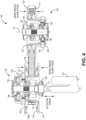
- Figure 4 illustrates an engine braking situation.
- the actuator 120 of the UCAS IVT system 100 may be activated to create an activation force to push the movable drive sheave member 101 of the drive clutch 102 towards the fixed drive sheave member 103 to create a drive clutch clamp force on the endless loop member 130.
- a drive clutch clamp force may be further generated as the result of torque received via the belt from the driven clutch 140 once an initial clamp force to establish torque communication between the clutches 102 and 140 is established.
- the clamping force provided by the driven clutch 140 may be added on to the clamping force provided by the actuator 120. This allows the force needed to be supplied by the actuator 120 to be relatively small.
- drive torque sensing assembly 200 of the drive clutch 102 includes drive cam 104.
- Drive cam 104 includes a cam hub portion 104a with cutout portions 205 that define cam profile surfaces 207a and 207b.
- the drive cam rollers 112 rotationally mounted on the arms of the drive spider 114 are positioned within respective cutout portions 205 in the drive cam 104 to engage the respective cam profile surfaces 207a and 207b of the drive cam 104. Rotation and torque are input into the cam profile surfaces by the drive cam rollers 112.
- the driven bias member 160 (compression spring) provides an initiation clamp force between the sheave faces and the belt faces to allow the torque sensitive elements to synchronize.
- the bulk of the clamp load is produced by the torque sensing assemblies 200 and 240.
- both the torque sensing assemblies 200 and 240 include a bias member 116 and 160, while in other embodiments only one of the torque sensing assemblies includes a bias member, as the initiation force can be supplied by an actuator 120 if desired.
- only one compression spring is used in one of the torque sensing assemblies that is not in operational communication with an actuator.
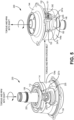
- FIG. 5 A low ratio configuration where torque and RPMs (rotation) are introduced in the drive post 106 of the drive clutch 102 via motor is illustrated in Figure 5 .
- Torque and rotation indicated by arrow 220, are in turn communicated to the cam assembly 104 via the drive cam rollers 112 of the drive spider 110.
- the torque and rotation are then communicated to the driven cam 144 of the driven torque sensing assembly 240 of the driven clutch 140 via the belt 130.
- the driven cam 144 in turn communicates the torque and rotation, indicated via arrow 242 to the spider 150 which is coupled to the driven post 146 that delivers the torque and RPM to the drivetrain.
- Figure 6 illustrates a high ratio configuration of the torque sensing assemblies 200 and 240 of the respective drive and driven clutch 102 and 140.
- torque and rotation are introduced in the drive post 106 of the drive clutch 102 via a motor or power source.
- the torque and rotation indicated by arrow 222, are in turn communicated to the drive cam 104 via the drive cam rollers 112 of the drive spider 114.
- drive cam roller 112 has moved along the cam profile surface 207a.
- the torque and rotation are then communicated to the driven cam 144 of driven torque sensing assembly 240 of the driven clutch 140 via the endless loop member 130.
- the driven cam 144 of the driven clutch 140 in turn communicates the torque and rotation, indicated by arrow 244, to the driven spider 150 which is coupled to the driven post 146 of the driven clutch 140 to deliver the torque and rotation to the drivetrain.
- drive bias member 116 of the drive torque sensing assembly 200 is illustrated.
- Drive bias member 116 provides a force load that is additive to a clamp load produced by torque cam elements of the drive torque sensing assembly 200.
- the bias member 116 provides an initiation clamp force between the sheave faces and the belt faces in each clutch to allow the torque sensitive elements to synchronize.
- the bulk of the clamp load may be produced by the torque cam elements of the drive torque sensing assembly 200.
- only the clutch 102 or 140 that is not in communication with the actuator 120 needs a bias member or compression spring in an embodiment.
- FIG. 7 illustrates a reverse torque configuration of the torque sensing assemblies 200 and 240 of the respective drive and driven clutches 102 and 140.
- torque and rotation is coming into the driven post 146 of the driven torque sensing assembly 240 of the driven clutch 140 from the drivetrain.
- the RPM of the driven post 146 divided by the belt contact diameter of the drive clutch 102 vs driven clutch 140 (CVT ratio) must be greater than the RPM of the drive post 106.
- the torque and rotation coming into the driven post 146 of the driven clutch 140 causes the driven spider 150 to rotate its arms towards cam profile surface 247b causing the driven cam rollers 152 to engage cam profile surface 247b. This is indicated by arrow 246.
- Torque and rotation on the driven cam 144 via driven cam rollers 152 are then communicated to drive cam 104 of the drive torque sensing assembly 200 of the drive clutch 102 via the endless loop member 130.
- This torque and rotation causes the drive cam 104 to rotate such that the cam profile surface 207b will engage the drive cam rollers 112 of spider 114 of drive torque sensing assembly 200. This is indicated by arrow 222.
- the drive cam roller 112 engaging cam profile surface 107b of the drive cam 104 will assert a force on the drive spider 114 and the drive post 106 to rotate as illustrated.
- the angled cam profile surfaces 247a and 247b in each cutout portion 245 of the driven cam 144 of the driven clutch 140 acts against the associated driven cam roller 152 of the drive spider 150 to generate a belt clamp force in the driven clutch 140.
- the drive and driven torque sensitive assemblies 200 and 240 in the respective drive clutch 102 and the driven clutch 140 generate a variable amount of clamp load in the respective drive clutch 102 and driven clutch 140 based on torque input supplied across the UCAS IVT system 100.
- the cam angles of the angled cam profile surfaces 207a, 207b, 247a and 247b of each respective drive and driven cam 104 and 144 are variable based a corresponding working diameter of the endless loop member 130 (belt). Moreover, the cam angles of the angled cam profile surfaces 207a, 207b, 247a and 247b of each cam 104 and 144 are configured to produce equivalent belt clamp load on each of the drive clutch 102 and the driven clutch 140 for all relative belt working diameters/IVT ratios.
- An effective "shifting force" in embodiments is equivalent in each clutch 102 and 140 for all relative belt working diameters/IVT ratios and torque inputs.
- a supplemental force must be supplied by an external actuator, such as actuator 120.
- the actuator 120 may include an electric, hydraulic, pneumatic, magnetic etc. actuation.
- each clutch 102 and 140 can be tailored to produce a net zero, or balanced level of shifting force. For any belt running diameter combination and level of torque being transmitted, neither clutch 102 or 140 will necessarily have a tendency to overpower the other to force a change in belt running diameter on either clutch 102 or 140.
- Required belt clamp to transmit power at each clutch 102 and 140 is produced by the associated torque sensitive assemblies 200 and 240. If an actuator 120 (electronic, hydraulic, pneumatic, magnetic) is used to facilitate the shifting function (change in belt running diameter in either pulley), the force required by the actuator 120 is greatly reduced. If RPM sensitive (centrifugal) elements, for example fly weights, are used to facilitate the shifting function, the size of those elements can be greatly reduced.
- a UCAS IVT system force graph 300 is illustrated.
- the graph 300 illustrates the sheave displacement for the driven clutch 140 and the drive clutch 102 for a given belt force in an example embodiment.
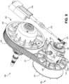
- Figures 9 through 11 illustrates another embodiment of a UCAS IVT 400.
- Figure 9 illustrates a side perspective view of the UCAS IVT 400
- Figure 10 illustrates a cross sectional top view of the UCAS IVT 400
- Figure 11 further illustrates an unassembled side view of the drive clutch 402 of UCAS IVT 400.
- UCAS IVT 400 includes a drive clutch 402 and a driven clutch 444 that are in operational communication to transfer torque and rotation via endless loop member such as a belt 431.
- the drive clutch 402 includes a fixed drive sheave member 410 that is mounted on a drive post 426 in an axially and rotationally fixed connection.
- a movable drive sheave member 412 is slidable mounted on the drive post 426.
- Mounted on the drive post 426 between the fixed drive sheave member 410 and the movable drive sheave member 412 is idler bearing 407.
- a spacer 409 Positioned between the movable drive sheave member 412 and the drive post 426 is a spacer 409 that allows the movable drive sheave member 412 to slide axially out of contact with the idler bearing 407.
- the spacer 409 is seated against a shoulder of the drive post 426 via drive spider 430 with a jam nut 421.
- the moveable drive sheave member 402 in this embodiment includes two cam assemblies.
- the first cam assembly is part of a drive torque sensitive assembly that works similar to the torque sensitive assemblies described above.
- This drive torque sensitive assembly includes the drive spider 430 and drive cam 406.
- the drive spider 430 is rotationally fixed to the drive post 426.
- Rollers 420 are rotationally coupled to ends of arms of the drive spider 430 and are positioned within cutout sections 425 of drive cam 406.
- the rollers 420 of the drive spider 430 selectively engage angled cam profile surfaces of the cutout sections 425 of the drive cam to transfer torque and rotation.
- the drive cam 425 is coupled to the movable drive sheave member 412 via fasteners 417.
- the second cam assembly is part of an activation system to selectively move the moveable drive sheave member 412 independent from the drive torque sensitive assembly.
- the activation assembly includes an activation cam 404.
- the activation can 404 has cutout sections 411 or portions and roller guide cutout sections 405. Rollers 420, that are rotationally mounted on arms of an activation spider 426, are positioned within the roller guide cutout sections 405 of the activation cam 404.
- a bearing 432 is positioned between a post extending end portion 406a of the drive cam 404 and the activation spider 426 to allow the activation spider to rotate in relation to the drive cam 404.
- the bearing 432 and activation spider 426 are retained on the post extending end portion 406a of the drive cam 406 via retaining member 427 and 429.
- a spider guide 435 with extending spider guide arms 435a and 435b is locked rotationally and axially to a chassis (not shown) with fasteners.
- a central portion of the spider guide 435 is mounted on a post extending end portion 404a of the activation cam 404 via retaining members 436 and 437.
- the spider guide arms 435a and 435b are received in the cutout sections 411 of the activation cam 404 to reach the activation spider 426.
- Sleeve bushings 423 in passages in the activation spider 426 receive ends of the spider guide arms 435a and 435b.
- the spider guide 435 prevents the actuator spider 427 from rotating as the actuator cam 404 pivots (rotates) due to actuator 470 travel.
- the actuator spider 426 is limited to axial travel only and transmits axial force (originating from the actuator 470) to the activation cam 404 (which is rotating at a high speed) via bearing 432. Axial travel of the actuator 470 is communicated to the movable drive sheave member 412.
- the torque sensitive assemblies in the drive and driven clutch 402 and 440 work similar to torque sensitive assemblies 200 and 240 described above.
- a different activation arrangement is used in the drive clutch 402.
- the activation arrangement includes the actuator 470 and the activation cam 404 arrangement.
- An elongated activation member 472 with an attachment member 474 is operationally coupled to the actuator 470.
- the attachment member 474 is pivotally coupled to an activation bracket 466.
- Activation bracket 466 is connected to the actuation cam 404 that pivots relative to the actuation cam spider 426 to convert rotational torque from the actuation cam 404 to linear force at the actuation spider 426, and ultimately the moveable drive sheave member 412 of drive clutch 402.
- Rotational movement of the activation bracket 466 via the actuator 470 rotates the actuation cam 404.
- the cam rollers 428 of the activation spider 426 ride in the angled roller guide cutout sections 405 of the actuation cam 404 as the actuator 470 rotates the actuation cam 404.
- Rotation of the activation cam 404 axially moves the actuation spider 426 and actuator bearing 432. Since the movable drive sheave member 412 is in operational communication with the activation spider 426 via drive cam 406, axial movement of the activation spider 426 axially moves the movable drive sheave member 412.
- rotation of the actuation cam 404 via the actuator 470 is used achieve a desired, supplemental clamp pressure on the belt 431 at the drive clutch 402 in addition to bulk clamp forces generated by torque loads across drive cam 406 and drive spider 430.
- an actuator may be operationally coupled to its associated sheave in a direct or indirect connection configuration.
- an intermediate mechanical system between the actuator and associated sheave can be employed to achieve a desirable mounting location of the actuator, to convert a linier actuator motion to a rotational motion or vice-versa, and to employ a mechanical advantage (force multiplier) between the actuator and associated sheave.
- the actuator may be coupled to either the drive or driven clutch.
- a bias member compression spring
- bias members may not be included.
- a vehicle 500 that implements a UCAS IVT of an example embodiment is illustrated.
- the vehicle is illustrated as including a motor 502 that provides engine torque and rotation.
- a drive post of a drive clutch 102 of the UCAS IVT is operationally coupled to the motor 502.
- a belt 130 communicates torque and rotation between the drive clutch and the driven clutch 140.
- the driven clutch 140 includes a driven post that is operationally coupled to communicate torque and rotation to the drivetrain.
- the drivetrain in this example includes a transmission 510, rear prop shaft 522, a rear differential 524, rear half shafts 526a and 526b and wheels 528a and 528b.
- the drivetrain, in this example further includes a front prop shaft 516, a front differential 521, front half shafts 518a and 518b and front wheels 520a and 520b.
- the actuator 120 controls the drive clutch 102 to achieve ratio change across system 100 or 400 as described above.
- a controller 504 controls the actuator 120 based on operation instruction stored in a memory and sensor information received by sensors 506.
- the sensors 506 may include motor sensors, transmission sensors, brake sensors, gear selection sensors, throttle position sensor, ground speed sensors, inclination sensors, temperature sensors, suspension travel sensors, etc.
- controller 504 may include any one or more of a processor, microprocessor, a digital signal processor (DSP), an application specific integrated circuit (ASIC), a field program gate array (FPGA), or equivalent discrete or integrated logic circuitry.
- controller 504 may include multiple components, such as any combination of one or more microprocessors, one or more controllers, one or more DSPs, one or more ASICs, one or more FPGAs, as well as other discrete or integrated logic circuitry.
- the functions attributed to the controller 504 herein may be embodied as software, firmware, hardware or any combination thereof.
- the controller 504 may be part of a system controller, such as an engine control unit or transmission control unit, or a component controller.
- the memory may include computer-readable operating instructions that, when executed by the controller provides functions of the UCAS IVT system.
- the computer readable instructions may be encoded within the memory 507.
- Memory 507 may comprise computer readable storage media including any volatile, nonvolatile, magnetic, optical, or electrical media, such as, but not limited to, a random access memory (RAM), read-only memory (ROM), non-volatile RAM (NVRAM), electrically-erasable programmable ROM (EEPROM), flash memory, or any other storage medium.
- RAM random access memory
- ROM read-only memory
- NVRAM non-volatile RAM
- EEPROM electrically-erasable programmable ROM
- flash memory or any other storage medium.
Landscapes
- Engineering & Computer Science (AREA)
- General Engineering & Computer Science (AREA)
- Mechanical Engineering (AREA)
- Transmissions By Endless Flexible Members (AREA)
Claims (11)
- Stufenloses schaltbares Getriebe mit einheitlicher Klemmenbetätigung, nachfolgend hierin UCAS-IVT-System genannt, wobei das UCAS-IVT-System (100, 400) Folgendes umfasst:eine Antriebskupplung (102, 402), beinhaltendeinen Antriebspfosten (106, 426), der konfiguriert ist, um an einen Motor (502) gekoppelt zu sein, um Drehmoment zwischen dem Motor (502) und dem Antriebspfosten (106, 426) zu übertragen,ein bewegbares Antriebsscheibenelement (101, 412), das an dem Antriebspfosten (106, 426) montiert ist,ein festes Antriebsscheibenelement (103, 410), das an dem Antriebspfosten (106, 426) montiert ist, undeine antriebsdrehmomentempfindliche Baugruppe (200), die konfiguriert ist, um das bewegbare Antriebsscheibenelement (101, 412) axial auf dem Antriebspfosten (106, 426) in Bezug auf das feste Antriebsscheibenelement (103, 410) zu bewegen, basierend zumindest auf Drehmoment, das auf die antriebsdrehmomentempfindliche Baugruppe (200) durch den Antriebspfosten (106, 426) angewendet wird;eine angetriebene Kupplung (140, 440), wobei die Antriebskupplung (102, 402) und die angetriebene Kupplung (140, 440) konfiguriert sind, um Drehmoment und Drehung zwischeneinander mit einem Endlosschleifenelement des Getriebesystems (130, 431) zu übertragen, wobei die angetriebene Kupplung (140, 440) Folgendes beinhaltet,einen angetriebenen Pfosten (146, 446), der konfiguriert ist, um an einen Antriebsstrang gekoppelt zu sein, um Drehmoment zwischen dem angetriebenen Pfosten (146, 446) und dem Antriebsstrang zu übertragen,ein bewegbares angetriebenes Scheibenelement (143, 444), das an dem angetriebenen Pfosten (146, 446) montiert ist,ein festes angetriebenes Scheibenelement (141, 442), das an dem angetriebenen Pfosten (146, 446) montiert ist, undeine angetriebene drehmomentempfindliche Baugruppe (240), die konfiguriert ist, um das bewegbare angetriebene Scheibenelement (143, 444) axial auf dem angetriebenen Pfosten (146, 446) in Bezug auf das feste angetriebene Scheibenelement (141, 442) zu bewegen, basierend zumindest auf Drehmoment, das auf die angetriebene drehmomentempfindliche Baugruppe (240) durch das Endlosschleifenelement (130, 431) angewendet wird;wobei die angetriebene drehmomentempfindliche Baugruppe (240) Folgendes umfasst:eine angetriebene Spinne (150), die an den angetriebenen Pfosten (146) gekoppelt ist, wobei Drehung der angetriebenen Spinne (150) an die Drehung des angetriebenen Pfostens (146) fixiert ist und die angetriebene Spinne (150) zumindest einen angetriebenen Spinnenarm beinhaltet,eine angetriebene Nockenrolle (152), die drehbar an jeden von dem zumindest einen angetriebenen Spinnenarm gekoppelt ist;eine angetriebene Nocke (144), die an das bewegbare angetriebene Scheibenelement (141) gekoppelt ist, wobei die angetriebene Nocke (144) zumindest einen ausgeschnittenen Abschnitt (245) aufweist, der angetriebene Nockenprofiloberflächen (247a, 247b) bildet, wobei die angetriebene Nockenrolle (152) innerhalb eines ausgeschnittenen Abschnittes (245) des zumindest einen ausgeschnittenen Abschnittes (245) positioniert ist, wobei jede angetriebene Nockenrolle (152) assoziierte angetriebene Nockenprofiloberflächen (247a, 247b) in Eingriff nimmt, um Drehmoment und Drehung zwischen der angetriebenen Spinne (150) und der angetriebenen Nocke (144) zu übertragen; undzumindest einen Aktor (120, 460), der an eines von dem bewegbaren Antriebsscheibenelement (101, 412) der Antriebskupplung (102, 402) und dem bewegbaren angetriebenen Scheibenelement (143, 444) der angetriebenen Kupplung (140, 440) gekoppelt ist, um das jeweilige eine von dem bewegbaren Antriebsscheibenelement (101, 412) und dem bewegbaren angetriebenen Scheibenelement (143, 444) unabhängig von der jeweiligen antriebsdrehmomentempfindlichen Baugruppe (200) und angetriebenen drehmomentempfindlichen Baugruppe (240) selektiv zu bewegen, um zumindest eines von Folgendem zu erreichen: eine gleichmäßigen Klemmung des Endlosschleifenelements (130, 431) zwischen der Antriebskupplung (102, 402) und der angetriebenen Kupplung (140, 440); und eine Verhältnisänderung über das UCAS-IVT-System (100, 400).
- UCAS-IVT-System (100, 400) nach Anspruch 1, wobei die Antriebskupplung (102) ferner Folgendes umfasst:eine Aktivierungsspinne (114, 430), die Aktivierungsrollen (212, 420) beinhaltet, wobei die Aktivierungsspinne (114, 430) konfiguriert ist, um sich axial zu bewegen; undeine Aktivierungsnocke (104, 404) mit Rollenführungsausschnittsabschnitten (205), wobei die Aktivierungsrollen (212, 420) innerhalb der Rollenführungsausschnittsabschnitte (205) der Aktivierungsnocke (104, 404) aufgenommen sind, wobei der zumindest eine Aktor (120, 460) an die Aktivierungsnocke (104, 404) wirkgekoppelt ist, um die Aktivierungsnocke (104, 404) selektiv zu drehen, um zu bewirken, dass die Aktivierungsspinne (114, 430) ein assoziiertes eines von dem bewegbaren Antriebsscheibenelement (101) und dem bewegbaren angetriebenen Scheibenelement (143) unabhängig von der antriebsdrehmomentempfindlichen Baugruppe (200) bewegt.
- UCAS-IVT-System (400) nach Anspruch 2, ferner umfassend;ein längliches Aktivierungselement (462), das an den zumindest einen Aktor (440) wirkgekoppelt ist;ein Befestigungselement (464), das an ein Ende des länglichen Aktivierungselements (462) wirkgekoppelt ist; undeine Aktivierungshalterung (466), die an die Aktivierungsnocke (404) wirkgekoppelt ist, wobei das Befestigungselement (464) schwenkbar an die Aktivierungshalterung (466) gekoppelt ist.
- UCAS-IVT-System (100) nach Anspruch 1, wobei der zumindest eine Aktor (120) konfiguriert ist, um eines von dem bewegbaren Antriebsscheibenelement (101) und dem bewegbaren angetriebenen Scheibenelement (141) zu schieben, um eines von gleichmäßiger Klemmung des Endlosschleifenelements (130) und Klemmvorspannung zu erreichen, um eine Änderung des Verhältnisses über das UCAS-IVT-System (100) zu produzieren.
- UCAS-IVT-System (100, 400) nach Anspruch 1, ferner umfassend;zumindest einen Sensor (506) zum Erzeugen von Sensorinformationen, wobei der zumindest eine Sensor (506) zumindest eines von einem Motorsensor, einem Getriebesensor, einem Bremssensor, einem Gangsensor, einem Gangwahlsensor, einem Drosselpositionssensor, einem Bodengeschwindigkeitssensor, einem Neigungssensor, einem Temperatursensor und einem Aufhängungswegsensor ist;zumindest einen Speicher (507) zum Speichern von zumindest Betriebsanweisungen, die Funktionen des UCAS-IVT-Systems (100, 400) bereitstellen; undeine Steuerung (504), die konfiguriert ist, um den Aktor (120, 460) basierend auf den gespeicherten Betriebsanweisungen und den Sensorinformationen zu steuern.
- UCAS-IVT-System (100, 400) nach Anspruch 1, wobei die antriebsdrehmomentempfindliche Baugruppe (200) ferner Folgendes umfasst:eine Antriebsspinne (114), die an den Antriebspfosten (106) gekoppelt ist, wobei Drehung der Antriebsspinne (114) an die Drehung des Antriebspfostens (106) fixiert ist, wobei die Antriebsspinne (114) zumindest einen Antriebsspinnenarm beinhaltet;eine Antriebsnockenrolle (112), die drehbar an jeden Antriebsspinnenarm gekoppelt ist;eine Antriebsnocke (104), die an das bewegbare Antriebsscheibenelement (101) gekoppelt ist, wobei die Antriebsnocke (104) zumindest einen ausgeschnittenen Abschnitt (205) aufweist, der Antriebsnockenprofiloberflächen (207a, 207b) bildet, wobei jede Antriebsnockenrolle (112) innerhalb eines ausgeschnittenen Abschnittes (205) des zumindest einen ausgeschnittenen Abschnittes (205) positioniert ist, wobei jede Antriebsnockenrolle (112) konfiguriert ist, um assoziierte Antriebsnockenprofiloberflächen (207a, 207b) in Eingriff zu nehmen, um Drehmoment und Drehung zwischen der Antriebsspinne (114) und der Antriebsnocke (104) zu kommunizieren.
- UCAS-IVT-System nach Anspruch 1, wobei die antriebsdrehmomentempfindliche Baugruppe (200) ferner Folgendes umfasst:
ein Antriebsvorspannelement (116), das konfiguriert ist, um eine ausgewählte Vorspannkraft auf das bewegbare Antriebsscheibenelement (101, 412) auszuüben, um eine Klemmkraft auf das Endlosschleifenelement (130, 431) zu initiieren. - UCAS-IVT-System nach Anspruch 1, wobei die angetriebene drehmomentempfindliche Baugruppe (240) ferner Folgendes umfasst:
ein angetriebenes Vorspannelement (160), das konfiguriert ist, um eine ausgewählte Vorspannkraft auf das bewegbare angetriebene Scheibenelement (141) auszuüben, um eine Klemmkraft auf das Endlosschleifenelement (130, 431) zu initiieren. - Fahrzeug (500) mit dem stufenlosen schaltbaren Getriebe mit einheitlicher Klemmenbetätigung (UCAS-IVT-System) nach einem der Ansprüche 1 bis 8, wobei das Fahrzeug (500) Folgendes umfasst:den Motor (502), der konfiguriert ist, um Triebwerksdrehmoment und Drehung zu erzeugen; undein Getriebe (510) des Antriebsstrangs (510, 516, 518a, 518b, 520a, 520b, 521, 522, 524, 526a, 526b, 528a, 528b), das an den angetriebenen Pfosten wirkgekoppelt ist.
- Fahrzeug nach Anspruch 9, ferner umfassend:zumindest einen Sensor (506) zum Erzeugen von Sensorinformationen, wobei der zumindest eine Sensor (506) zumindest eines von einem Motorsensor, einem Getriebesensor, einem Bremssensor, einem Gangsensor, einem Gangwahlsensor, einem Drosselpositionssensor, einem Bodengeschwindigkeitssensor, einem Neigungssensor, einem Temperatursensor und einem Aufhängungswegsensor ist;zumindest einen Speicher (507) zum Speichern von zumindest Betriebsanweisungen, die Funktionen des UCAS-IVT-Systems (100, 400) bereitstellen; undeine Steuerung (504), die konfiguriert ist, um den zumindest einen Aktor (120, 460) basierend auf den gespeicherten Betriebsanweisungen und den Sensorinformationen zu steuern.
- Fahrzeug nach Anspruch 9, wobei der zumindest eine Aktor konfiguriert ist, um eines von dem bewegbaren Antriebsscheibenelement und dem bewegbaren angetriebenen Scheibenelement zu schieben, um eines von dem bewegbaren Antriebsscheibenelement und dem angetriebenen Scheibenelement selektiv zu bewegen.
Applications Claiming Priority (2)
| Application Number | Priority Date | Filing Date | Title |
|---|---|---|---|
| US201962869181P | 2019-07-01 | 2019-07-01 | |
| PCT/US2020/040442 WO2021003232A1 (en) | 2019-07-01 | 2020-07-01 | Uniform clamp actuated shift infinitely variable transmission system |
Publications (2)
| Publication Number | Publication Date |
|---|---|
| EP3994375A1 EP3994375A1 (de) | 2022-05-11 |
| EP3994375B1 true EP3994375B1 (de) | 2024-12-18 |
Family
ID=71728986
Family Applications (1)
| Application Number | Title | Priority Date | Filing Date |
|---|---|---|---|
| EP20743516.5A Active EP3994375B1 (de) | 2019-07-01 | 2020-07-01 | Stufenlos schaltbares getriebe mit einheitlicher klemmenbetätigung |
Country Status (7)
| Country | Link |
|---|---|
| US (1) | US11592100B2 (de) |
| EP (1) | EP3994375B1 (de) |
| CN (1) | CN114127446B (de) |
| CA (1) | CA3145546A1 (de) |
| ES (1) | ES3004391T3 (de) |
| MX (1) | MX2022000005A (de) |
| WO (1) | WO2021003232A1 (de) |
Families Citing this family (4)
| Publication number | Priority date | Publication date | Assignee | Title |
|---|---|---|---|---|
| US11732786B2 (en) * | 2021-07-30 | 2023-08-22 | Textron Innovations Inc. | Continuously variable transmission having tunable acceleration and deceleration |
| WO2023192166A1 (en) * | 2022-03-29 | 2023-10-05 | Gates Corporation | Cam-controlled continuously variable transmission systems |
| CN121443867A (zh) * | 2023-07-19 | 2026-01-30 | 蒂姆工业公司 | 具有选定的每分钟转数输出的无级变速器 |
| AU2024287226A1 (en) * | 2024-01-02 | 2025-08-21 | Polaris Industries Inc. | Driven clutch for continuously variable transmission |
Citations (3)
| Publication number | Priority date | Publication date | Assignee | Title |
|---|---|---|---|---|
| US3043152A (en) * | 1960-03-14 | 1962-07-10 | Reimers Getriebe Kg | Hydraulic control mechanism for infinitely variable gears |
| US4982822A (en) * | 1986-12-01 | 1991-01-08 | Borg-Warner Corporation | Control system for controlling the line pressure in a continuously variable transmission |
| US20180172150A1 (en) * | 2016-12-16 | 2018-06-21 | Ecole De Technologie Superieure | Electromechanically actuated continuously variable transmission system and method of controlling thereof |
Family Cites Families (69)
| Publication number | Priority date | Publication date | Assignee | Title |
|---|---|---|---|---|
| US2050358A (en) * | 1933-11-13 | 1936-08-11 | Isaac E Mcelroy | Variable speed pulley |
| US2283392A (en) * | 1940-12-05 | 1942-05-19 | F L Dryg | Variable speed pulley |
| US2651208A (en) * | 1949-10-06 | 1953-09-08 | Patentverwertung Reimers W Gmbh | Pulley for variable speed transmissions |
| FR1106748A (fr) | 1954-06-01 | 1955-12-22 | Variateur de vitesse | |
| DE1081733B (de) * | 1958-07-19 | 1960-05-12 | Reimers Getriebe K G | Steuereinrichtung an stufenlos verstellbaren Getrieben mit zwischen axial verschiebbaren Kegelscheibenpaaren laufenden Zugmittelstraengen und hydraulischer Verstelleinrichtung |
| US3052132A (en) * | 1958-12-12 | 1962-09-04 | Reimers Getriebe Kg | Control mechanism for infinitely variable gears |
| US3110188A (en) * | 1961-01-16 | 1963-11-12 | Reimers Getriebe Kg | Infinitely variable cone pulley gear |
| US3110189A (en) * | 1961-01-25 | 1963-11-12 | Reimers Getriebe Kg | Infinitely variable pulley gear |
| DE1650803B1 (de) * | 1967-07-25 | 1971-07-08 | Piv Antrieb Reimers Kg Werner | Stufenlos einstellbares kegelscheiben umschlingungs getriebe |
| DE2539094C2 (de) * | 1975-09-03 | 1977-09-08 | PIV Antrieb Werner Reimers KG, 6380 Bad Homburg | Stufenlos einstellbares Kegelscheibengetriebe |
| US4005609A (en) * | 1976-01-19 | 1977-02-01 | Bendall Wilfrid H | Automatic variable speed transmission |
| JPS5717153Y2 (de) * | 1976-11-12 | 1982-04-09 | ||
| US4348197A (en) * | 1980-01-28 | 1982-09-07 | Dayco Corporation | Torque-sensing pulley and drive system |
| DE3028490C2 (de) * | 1980-07-26 | 1983-01-13 | P.I.V. Antrieb Werner Reimers GmbH & Co KG, 6380 Bad Homburg | Stufenlos einstellbares Kegelscheibengetriebe |
| US4380444A (en) * | 1981-04-27 | 1983-04-19 | John Dolza | Variable ratio belt drive |
| US4523917A (en) * | 1983-12-27 | 1985-06-18 | Dana Corporation | Variable pitch diameter torque sensing pulley assembly |
| EP0383282B1 (de) * | 1989-02-16 | 1994-04-20 | Bando Chemical Industries, Limited | Kegelscheibengetriebe |
| DE3917466C1 (de) * | 1989-05-30 | 1990-09-20 | P.I.V. Antrieb Werner Reimers Gmbh & Co Kg, 6380 Bad Homburg, De | |
| DE4120540C1 (de) * | 1991-06-21 | 1992-11-05 | Dr.Ing.H.C. F. Porsche Ag, 7000 Stuttgart, De | |
| IN189939B (de) * | 1993-12-20 | 2003-05-17 | Torotrak Dev Ltd | |
| US5720681A (en) * | 1996-03-18 | 1998-02-24 | Benson; Steven R. | Torque responsive actuation device |
| JP3513314B2 (ja) * | 1996-02-20 | 2004-03-31 | 富士重工業株式会社 | 車両用無段変速装置の制御装置 |
| JPH09317844A (ja) * | 1996-05-28 | 1997-12-12 | Bando Chem Ind Ltd | 無段変速機 |
| JP3217285B2 (ja) * | 1996-12-06 | 2001-10-09 | バンドー化学株式会社 | 車両用無段変速機及びそれを用いた芝刈り用トラクタ |
| JP3796916B2 (ja) * | 1997-08-25 | 2006-07-12 | マツダ株式会社 | トロイダル式無段変速機の制御装置 |
| DE19857709B4 (de) * | 1997-12-22 | 2006-03-23 | Luk Gs Verwaltungs Kg | Getriebe |
| US6120399A (en) * | 1998-06-11 | 2000-09-19 | Product Research And Development, Inc. | Continuously variable transmission driven element |
| US6146295A (en) * | 1998-06-25 | 2000-11-14 | Mor; John Matthew | Encapsulated roller for helical bearing surfaces |
| DE19912963B4 (de) * | 1999-03-23 | 2005-05-19 | Dr.Ing.H.C. F. Porsche Ag | Vorrichtung und Verfahren zum Steuern eines selbsttätig schaltenden Getriebes |
| US6231477B1 (en) * | 1999-05-21 | 2001-05-15 | Daimlerchrysler Corporation | Apparatus and method for providing automatic shift modes in an automatic transmission |
| US6743129B1 (en) * | 1999-11-29 | 2004-06-01 | Team Industries, Inc. | Clutch with no relative rotation |
| US6569043B2 (en) * | 1999-11-29 | 2003-05-27 | Team Industries, Inc. | Clutch with a one-way torque carrying bearing |
| US6379274B1 (en) * | 1999-11-29 | 2002-04-30 | Cvtech R & D Inc. | Driven pulley |
| JP4752089B2 (ja) * | 2000-05-17 | 2011-08-17 | トヨタ自動車株式会社 | ベルト式無段変速機 |
| DE10139121A1 (de) * | 2000-09-08 | 2002-03-21 | Luk Lamellen & Kupplungsbau | Anpreßsystem |
| JP3750523B2 (ja) * | 2000-12-12 | 2006-03-01 | トヨタ自動車株式会社 | 車両用無段変速機の変速制御装置 |
| FR2824376B1 (fr) * | 2001-05-04 | 2003-07-04 | Commerciale Et D Engineering S | Transmission de vitesse pour tondeuse a gazon automotrice et tondeuse equipee d'une telle transmission |
| FR2841190B1 (fr) | 2002-06-21 | 2009-11-06 | Luk Lamellen & Kupplungsbau | Procede de commande et/ou de reglage d'une boite de vitesse et strategie de changements de rapports pour une boite de vitesses |
| US7207920B2 (en) * | 2003-10-01 | 2007-04-24 | Pivario Ab | V-belt continuously variable transmission for a vehicle engine |
| DE10351983B4 (de) | 2003-11-07 | 2007-07-05 | Audi Ag | Getriebesteuervorrichtung mit mehreren parametrierbaren Getriebesteuerfunktionen und entsprechendes Getriebesteuerverfahren |
| US7300370B2 (en) * | 2004-05-26 | 2007-11-27 | Gordon Wood | Clutch system for belted constant velocity transmission |
| US7771300B2 (en) * | 2005-05-02 | 2010-08-10 | Purdue Research Foundation | Devices for electrically assisting and actuating continuously variable transmissions |
| FR2889866B1 (fr) * | 2005-07-29 | 2007-10-19 | France Reducteurs Soc Par Acti | Variateur de vitesse a courroie et engin automoteur a vitesse d'avancement variable equipe d'un tel variateur |
| JP4842741B2 (ja) * | 2006-09-01 | 2011-12-21 | ヤマハ発動機株式会社 | 鞍乗型車両 |
| JP4941133B2 (ja) * | 2007-07-03 | 2012-05-30 | トヨタ自動車株式会社 | 車両用無段変速機の変速制御装置 |
| JP4577342B2 (ja) * | 2007-09-10 | 2010-11-10 | トヨタ自動車株式会社 | 油圧制御装置 |
| JP4818337B2 (ja) * | 2008-09-17 | 2011-11-16 | 本田技研工業株式会社 | 車両の制御装置 |
| JP4725634B2 (ja) * | 2008-11-13 | 2011-07-13 | トヨタ自動車株式会社 | 無段変速機 |
| JP5170255B2 (ja) * | 2008-12-02 | 2013-03-27 | トヨタ自動車株式会社 | シーブ位置決め装置 |
| WO2011032252A1 (en) * | 2009-09-15 | 2011-03-24 | Consortium De Recherche Brp - Université De Sherbrooke S.E.N.C. | Method of controlling a hydraulic continuously variable transmission |
| US8565990B2 (en) * | 2009-11-13 | 2013-10-22 | Ford Global Technologies, Llc. | Vehicle and method for controlling engine start in a vehicle |
| US20110152020A1 (en) * | 2009-12-23 | 2011-06-23 | Brind Amour Francois | Electronically controlled continuously variable transmission with axially movable torque transmitting mechanism |
| US8753248B2 (en) * | 2009-12-24 | 2014-06-17 | Yamaha Hatsudoki Kabushiki Kaisha | Vehicle and method for controlling the same |
| DE102010030495B3 (de) * | 2010-06-24 | 2011-11-03 | Zf Friedrichshafen Ag | Verfahren zum Betreiben einer Getriebeeinrichtung |
| JP5337137B2 (ja) * | 2010-12-06 | 2013-11-06 | 富士重工業株式会社 | 車両の変速制御装置 |
| US9429235B2 (en) * | 2011-10-14 | 2016-08-30 | Polaris Industries Inc. | Primary clutch electronic CVT |
| CA2886623A1 (en) * | 2012-09-28 | 2014-04-03 | Brp-Powertrain Gmbh & Co. Kg | Pneumatically assisted continuously variable transmission |
| JP2014074424A (ja) | 2012-10-03 | 2014-04-24 | Yamaha Motor Co Ltd | 鞍乗型車両 |
| US9057439B2 (en) * | 2013-03-14 | 2015-06-16 | Team Industries, Inc. | Infinitely variable transmission with IVT traction ring controlling assemblies |
| JP5906262B2 (ja) | 2014-01-15 | 2016-04-20 | 富士重工業株式会社 | 無段変速機の変速制御装置 |
| CN106461036B (zh) * | 2014-03-31 | 2019-05-28 | 庞巴迪动力产品公司 | 无级变速器主动带轮 |
| US9759313B2 (en) * | 2014-11-26 | 2017-09-12 | Polaris Industries Inc. | Electronic shifting of a transmission |
| US20170082193A1 (en) * | 2015-09-17 | 2017-03-23 | Dana Limited | Simulated stepped gear ratio control method for a ball-type continuously variable transmission |
| US10486705B2 (en) * | 2015-10-12 | 2019-11-26 | Team Industries, Inc. | Shift control |
| WO2017152983A1 (en) * | 2016-03-10 | 2017-09-14 | Punch Powertrain N.V. | Continuously variable transmission and method for transferring torque |
| WO2019030586A1 (en) * | 2017-08-10 | 2019-02-14 | Agco Corporation | Torque-sensing variable speed belt drive with helical strut |
| US20190092312A1 (en) * | 2017-09-26 | 2019-03-28 | Team Industries, Inc. | Multi-mode cvt controller |
| WO2019182951A1 (en) * | 2018-03-19 | 2019-09-26 | Polaris Industries Inc. | Electronic cvt with friction clutch |
| JP7207336B2 (ja) * | 2020-01-09 | 2023-01-18 | トヨタ自動車株式会社 | ベルト式無段変速機のベルト滑り診断装置 |
-
2020
- 2020-07-01 CA CA3145546A patent/CA3145546A1/en active Pending
- 2020-07-01 MX MX2022000005A patent/MX2022000005A/es unknown
- 2020-07-01 US US16/918,184 patent/US11592100B2/en active Active
- 2020-07-01 EP EP20743516.5A patent/EP3994375B1/de active Active
- 2020-07-01 WO PCT/US2020/040442 patent/WO2021003232A1/en not_active Ceased
- 2020-07-01 CN CN202080049057.4A patent/CN114127446B/zh active Active
- 2020-07-01 ES ES20743516T patent/ES3004391T3/es active Active
Patent Citations (3)
| Publication number | Priority date | Publication date | Assignee | Title |
|---|---|---|---|---|
| US3043152A (en) * | 1960-03-14 | 1962-07-10 | Reimers Getriebe Kg | Hydraulic control mechanism for infinitely variable gears |
| US4982822A (en) * | 1986-12-01 | 1991-01-08 | Borg-Warner Corporation | Control system for controlling the line pressure in a continuously variable transmission |
| US20180172150A1 (en) * | 2016-12-16 | 2018-06-21 | Ecole De Technologie Superieure | Electromechanically actuated continuously variable transmission system and method of controlling thereof |
Also Published As
| Publication number | Publication date |
|---|---|
| US11592100B2 (en) | 2023-02-28 |
| CN114127446A (zh) | 2022-03-01 |
| ES3004391T3 (en) | 2025-03-12 |
| WO2021003232A1 (en) | 2021-01-07 |
| EP3994375A1 (de) | 2022-05-11 |
| CN114127446B (zh) | 2025-09-02 |
| US20210003203A1 (en) | 2021-01-07 |
| CA3145546A1 (en) | 2021-01-07 |
| MX2022000005A (es) | 2022-03-17 |
Similar Documents
| Publication | Publication Date | Title |
|---|---|---|
| US11592100B2 (en) | Uniform clamp actuated shift infinitely variable transmission system | |
| JP6926379B2 (ja) | 連続可変変速機 | |
| CN104302949B (zh) | 无限变速式无级变速器、连续变速式无级变速器、方法、组件、子组件以及其部件 | |
| CA2926292C (en) | Cvt drive clutch | |
| EP0219223A2 (de) | Übertragungssysteme | |
| CA2555055A1 (en) | Transmission and constant speed accessory drive | |
| US20150024882A1 (en) | Driven Clutch with Engine Braking for a Continuously Variable Transmission | |
| US5057061A (en) | Continuously variable speed transmission | |
| US5004082A (en) | Starting device of an automatic transmission for vehicle | |
| US7163477B1 (en) | Continuously variable transmission with decoupled centrifugal weight | |
| JP2747803B2 (ja) | ベルト式自動変速機 | |
| CA2951857C (en) | A continuously variable transmission system, electromechanically operated, and its associated control method | |
| JP5310299B2 (ja) | ベルト式無段変速機を備える車両 | |
| US6317672B1 (en) | Controller for infinite speed ratio transmission | |
| JP2004169719A (ja) | トロイダル型無段変速機及び無段変速装置 | |
| TWI278407B (en) | Continuously variable ratio drive | |
| JP3162328B2 (ja) | 車載用vベルト式自動変速機 | |
| JPH10252880A (ja) | トロイダル型無段変速機の変速制御装置 | |
| CN100504120C (zh) | 换档机构的控制系统 | |
| EP0969229A2 (de) | Stufenloses Getriebe | |
| JPH0676824B2 (ja) | 無段変速機のライン圧制御装置 | |
| JPH0647350B2 (ja) | 自動車用無段変速装置 | |
| JP2000179674A (ja) | パワートレインの制御装置 | |
| JP2000179669A (ja) | パワートレインの制御装置 | |
| KR200207525Y1 (ko) | 무단변속기 |
Legal Events
| Date | Code | Title | Description |
|---|---|---|---|
| STAA | Information on the status of an ep patent application or granted ep patent |
Free format text: STATUS: UNKNOWN |
|
| STAA | Information on the status of an ep patent application or granted ep patent |
Free format text: STATUS: THE INTERNATIONAL PUBLICATION HAS BEEN MADE |
|
| PUAI | Public reference made under article 153(3) epc to a published international application that has entered the european phase |
Free format text: ORIGINAL CODE: 0009012 |
|
| STAA | Information on the status of an ep patent application or granted ep patent |
Free format text: STATUS: REQUEST FOR EXAMINATION WAS MADE |
|
| 17P | Request for examination filed |
Effective date: 20220121 |
|
| AK | Designated contracting states |
Kind code of ref document: A1 Designated state(s): AL AT BE BG CH CY CZ DE DK EE ES FI FR GB GR HR HU IE IS IT LI LT LU LV MC MK MT NL NO PL PT RO RS SE SI SK SM TR |
|
| DAV | Request for validation of the european patent (deleted) | ||
| DAX | Request for extension of the european patent (deleted) | ||
| STAA | Information on the status of an ep patent application or granted ep patent |
Free format text: STATUS: EXAMINATION IS IN PROGRESS |
|
| P01 | Opt-out of the competence of the unified patent court (upc) registered |
Effective date: 20230520 |
|
| 17Q | First examination report despatched |
Effective date: 20230609 |
|
| GRAP | Despatch of communication of intention to grant a patent |
Free format text: ORIGINAL CODE: EPIDOSNIGR1 |
|
| STAA | Information on the status of an ep patent application or granted ep patent |
Free format text: STATUS: GRANT OF PATENT IS INTENDED |
|
| INTG | Intention to grant announced |
Effective date: 20240712 |
|
| GRAS | Grant fee paid |
Free format text: ORIGINAL CODE: EPIDOSNIGR3 |
|
| GRAA | (expected) grant |
Free format text: ORIGINAL CODE: 0009210 |
|
| STAA | Information on the status of an ep patent application or granted ep patent |
Free format text: STATUS: THE PATENT HAS BEEN GRANTED |
|
| AK | Designated contracting states |
Kind code of ref document: B1 Designated state(s): AL AT BE BG CH CY CZ DE DK EE ES FI FR GB GR HR HU IE IS IT LI LT LU LV MC MK MT NL NO PL PT RO RS SE SI SK SM TR |
|
| REG | Reference to a national code |
Ref country code: CH Ref legal event code: EP |
|
| REG | Reference to a national code |
Ref country code: DE Ref legal event code: R096 Ref document number: 602020043356 Country of ref document: DE |
|
| REG | Reference to a national code |
Ref country code: IE Ref legal event code: FG4D |
|
| REG | Reference to a national code |
Ref country code: ES Ref legal event code: FG2A Ref document number: 3004391 Country of ref document: ES Kind code of ref document: T3 Effective date: 20250312 |
|
| REG | Reference to a national code |
Ref country code: LT Ref legal event code: MG9D |
|
| PG25 | Lapsed in a contracting state [announced via postgrant information from national office to epo] |
Ref country code: HR Free format text: LAPSE BECAUSE OF FAILURE TO SUBMIT A TRANSLATION OF THE DESCRIPTION OR TO PAY THE FEE WITHIN THE PRESCRIBED TIME-LIMIT Effective date: 20241218 |
|
| PG25 | Lapsed in a contracting state [announced via postgrant information from national office to epo] |
Ref country code: FI Free format text: LAPSE BECAUSE OF FAILURE TO SUBMIT A TRANSLATION OF THE DESCRIPTION OR TO PAY THE FEE WITHIN THE PRESCRIBED TIME-LIMIT Effective date: 20241218 |
|
| PG25 | Lapsed in a contracting state [announced via postgrant information from national office to epo] |
Ref country code: BG Free format text: LAPSE BECAUSE OF FAILURE TO SUBMIT A TRANSLATION OF THE DESCRIPTION OR TO PAY THE FEE WITHIN THE PRESCRIBED TIME-LIMIT Effective date: 20241218 |
|
| PG25 | Lapsed in a contracting state [announced via postgrant information from national office to epo] |
Ref country code: NO Free format text: LAPSE BECAUSE OF FAILURE TO SUBMIT A TRANSLATION OF THE DESCRIPTION OR TO PAY THE FEE WITHIN THE PRESCRIBED TIME-LIMIT Effective date: 20250318 |
|
| REG | Reference to a national code |
Ref country code: NL Ref legal event code: MP Effective date: 20241218 |
|
| PG25 | Lapsed in a contracting state [announced via postgrant information from national office to epo] |
Ref country code: LV Free format text: LAPSE BECAUSE OF FAILURE TO SUBMIT A TRANSLATION OF THE DESCRIPTION OR TO PAY THE FEE WITHIN THE PRESCRIBED TIME-LIMIT Effective date: 20241218 Ref country code: GR Free format text: LAPSE BECAUSE OF FAILURE TO SUBMIT A TRANSLATION OF THE DESCRIPTION OR TO PAY THE FEE WITHIN THE PRESCRIBED TIME-LIMIT Effective date: 20250319 |
|
| PG25 | Lapsed in a contracting state [announced via postgrant information from national office to epo] |
Ref country code: RS Free format text: LAPSE BECAUSE OF FAILURE TO SUBMIT A TRANSLATION OF THE DESCRIPTION OR TO PAY THE FEE WITHIN THE PRESCRIBED TIME-LIMIT Effective date: 20250318 |
|
| PG25 | Lapsed in a contracting state [announced via postgrant information from national office to epo] |
Ref country code: NL Free format text: LAPSE BECAUSE OF FAILURE TO SUBMIT A TRANSLATION OF THE DESCRIPTION OR TO PAY THE FEE WITHIN THE PRESCRIBED TIME-LIMIT Effective date: 20241218 |
|
| REG | Reference to a national code |
Ref country code: AT Ref legal event code: MK05 Ref document number: 1752451 Country of ref document: AT Kind code of ref document: T Effective date: 20241218 |
|
| PG25 | Lapsed in a contracting state [announced via postgrant information from national office to epo] |
Ref country code: SM Free format text: LAPSE BECAUSE OF FAILURE TO SUBMIT A TRANSLATION OF THE DESCRIPTION OR TO PAY THE FEE WITHIN THE PRESCRIBED TIME-LIMIT Effective date: 20241218 |
|
| PG25 | Lapsed in a contracting state [announced via postgrant information from national office to epo] |
Ref country code: PL Free format text: LAPSE BECAUSE OF FAILURE TO SUBMIT A TRANSLATION OF THE DESCRIPTION OR TO PAY THE FEE WITHIN THE PRESCRIBED TIME-LIMIT Effective date: 20241218 |
|
| PG25 | Lapsed in a contracting state [announced via postgrant information from national office to epo] |
Ref country code: IS Free format text: LAPSE BECAUSE OF FAILURE TO SUBMIT A TRANSLATION OF THE DESCRIPTION OR TO PAY THE FEE WITHIN THE PRESCRIBED TIME-LIMIT Effective date: 20250418 |
|
| PG25 | Lapsed in a contracting state [announced via postgrant information from national office to epo] |
Ref country code: PT Free format text: LAPSE BECAUSE OF FAILURE TO SUBMIT A TRANSLATION OF THE DESCRIPTION OR TO PAY THE FEE WITHIN THE PRESCRIBED TIME-LIMIT Effective date: 20250421 |
|
| PG25 | Lapsed in a contracting state [announced via postgrant information from national office to epo] |
Ref country code: EE Free format text: LAPSE BECAUSE OF FAILURE TO SUBMIT A TRANSLATION OF THE DESCRIPTION OR TO PAY THE FEE WITHIN THE PRESCRIBED TIME-LIMIT Effective date: 20241218 |
|
| PGFP | Annual fee paid to national office [announced via postgrant information from national office to epo] |
Ref country code: FR Payment date: 20250523 Year of fee payment: 6 |
|
| PG25 | Lapsed in a contracting state [announced via postgrant information from national office to epo] |
Ref country code: RO Free format text: LAPSE BECAUSE OF FAILURE TO SUBMIT A TRANSLATION OF THE DESCRIPTION OR TO PAY THE FEE WITHIN THE PRESCRIBED TIME-LIMIT Effective date: 20241218 Ref country code: AT Free format text: LAPSE BECAUSE OF FAILURE TO SUBMIT A TRANSLATION OF THE DESCRIPTION OR TO PAY THE FEE WITHIN THE PRESCRIBED TIME-LIMIT Effective date: 20241218 |
|
| PG25 | Lapsed in a contracting state [announced via postgrant information from national office to epo] |
Ref country code: SK Free format text: LAPSE BECAUSE OF FAILURE TO SUBMIT A TRANSLATION OF THE DESCRIPTION OR TO PAY THE FEE WITHIN THE PRESCRIBED TIME-LIMIT Effective date: 20241218 |
|
| PG25 | Lapsed in a contracting state [announced via postgrant information from national office to epo] |
Ref country code: CZ Free format text: LAPSE BECAUSE OF FAILURE TO SUBMIT A TRANSLATION OF THE DESCRIPTION OR TO PAY THE FEE WITHIN THE PRESCRIBED TIME-LIMIT Effective date: 20241218 |
|
| PG25 | Lapsed in a contracting state [announced via postgrant information from national office to epo] |
Ref country code: IT Free format text: LAPSE BECAUSE OF FAILURE TO SUBMIT A TRANSLATION OF THE DESCRIPTION OR TO PAY THE FEE WITHIN THE PRESCRIBED TIME-LIMIT Effective date: 20241218 |
|
| PG25 | Lapsed in a contracting state [announced via postgrant information from national office to epo] |
Ref country code: SE Free format text: LAPSE BECAUSE OF FAILURE TO SUBMIT A TRANSLATION OF THE DESCRIPTION OR TO PAY THE FEE WITHIN THE PRESCRIBED TIME-LIMIT Effective date: 20241218 |
|
| REG | Reference to a national code |
Ref country code: DE Ref legal event code: R097 Ref document number: 602020043356 Country of ref document: DE |
|
| PGFP | Annual fee paid to national office [announced via postgrant information from national office to epo] |
Ref country code: ES Payment date: 20250804 Year of fee payment: 6 |
|
| PG25 | Lapsed in a contracting state [announced via postgrant information from national office to epo] |
Ref country code: DK Free format text: LAPSE BECAUSE OF FAILURE TO SUBMIT A TRANSLATION OF THE DESCRIPTION OR TO PAY THE FEE WITHIN THE PRESCRIBED TIME-LIMIT Effective date: 20241218 |
|
| PGFP | Annual fee paid to national office [announced via postgrant information from national office to epo] |
Ref country code: DE Payment date: 20250528 Year of fee payment: 6 |
|
| PLBE | No opposition filed within time limit |
Free format text: ORIGINAL CODE: 0009261 |
|
| STAA | Information on the status of an ep patent application or granted ep patent |
Free format text: STATUS: NO OPPOSITION FILED WITHIN TIME LIMIT |
|
| REG | Reference to a national code |
Ref country code: CH Ref legal event code: L10 Free format text: ST27 STATUS EVENT CODE: U-0-0-L10-L00 (AS PROVIDED BY THE NATIONAL OFFICE) Effective date: 20251029 |
|
| 26N | No opposition filed |
Effective date: 20250919 |
|
| REG | Reference to a national code |
Ref country code: CH Ref legal event code: H13 Free format text: ST27 STATUS EVENT CODE: U-0-0-H10-H13 (AS PROVIDED BY THE NATIONAL OFFICE) Effective date: 20260224 |
|
| PG25 | Lapsed in a contracting state [announced via postgrant information from national office to epo] |
Ref country code: LU Free format text: LAPSE BECAUSE OF NON-PAYMENT OF DUE FEES Effective date: 20250701 |
|
| GBPC | Gb: european patent ceased through non-payment of renewal fee |
Effective date: 20250701 |
|
| REG | Reference to a national code |
Ref country code: BE Ref legal event code: MM Effective date: 20250731 |
|
| PG25 | Lapsed in a contracting state [announced via postgrant information from national office to epo] |
Ref country code: GB Free format text: LAPSE BECAUSE OF NON-PAYMENT OF DUE FEES Effective date: 20250701 |
|
| PG25 | Lapsed in a contracting state [announced via postgrant information from national office to epo] |
Ref country code: BE Free format text: LAPSE BECAUSE OF NON-PAYMENT OF DUE FEES Effective date: 20250731 |
|
| PG25 | Lapsed in a contracting state [announced via postgrant information from national office to epo] |
Ref country code: CH Free format text: LAPSE BECAUSE OF NON-PAYMENT OF DUE FEES Effective date: 20250731 |