EP2518855A2 - Schaltungskoordinierung verteilter Gleichstrom-Gleichstrom-Umwandler für hocheffiziente photovoltaische Kraftwerke - Google Patents
Schaltungskoordinierung verteilter Gleichstrom-Gleichstrom-Umwandler für hocheffiziente photovoltaische Kraftwerke Download PDFInfo
- Publication number
- EP2518855A2 EP2518855A2 EP20120157063 EP12157063A EP2518855A2 EP 2518855 A2 EP2518855 A2 EP 2518855A2 EP 20120157063 EP20120157063 EP 20120157063 EP 12157063 A EP12157063 A EP 12157063A EP 2518855 A2 EP2518855 A2 EP 2518855A2
- Authority
- EP
- European Patent Office
- Prior art keywords
- converter
- power
- converters
- power plant
- string
- Prior art date
- Legal status (The legal status is an assumption and is not a legal conclusion. Google has not performed a legal analysis and makes no representation as to the accuracy of the status listed.)
- Withdrawn
Links
Images




Classifications
-
- H—ELECTRICITY
- H02—GENERATION; CONVERSION OR DISTRIBUTION OF ELECTRIC POWER
- H02M—APPARATUS FOR CONVERSION BETWEEN AC AND AC, BETWEEN AC AND DC, OR BETWEEN DC AND DC, AND FOR USE WITH MAINS OR SIMILAR POWER SUPPLY SYSTEMS; CONVERSION OF DC OR AC INPUT POWER INTO SURGE OUTPUT POWER; CONTROL OR REGULATION THEREOF
- H02M3/00—Conversion of DC power input into DC power output
- H02M3/02—Conversion of DC power input into DC power output without intermediate conversion into AC
- H02M3/04—Conversion of DC power input into DC power output without intermediate conversion into AC by static converters
- H02M3/10—Conversion of DC power input into DC power output without intermediate conversion into AC by static converters using discharge tubes with control electrode or semiconductor devices with control electrode
- H02M3/145—Conversion of DC power input into DC power output without intermediate conversion into AC by static converters using discharge tubes with control electrode or semiconductor devices with control electrode using devices of a triode or transistor type requiring continuous application of a control signal
- H02M3/155—Conversion of DC power input into DC power output without intermediate conversion into AC by static converters using discharge tubes with control electrode or semiconductor devices with control electrode using devices of a triode or transistor type requiring continuous application of a control signal using semiconductor devices only
- H02M3/156—Conversion of DC power input into DC power output without intermediate conversion into AC by static converters using discharge tubes with control electrode or semiconductor devices with control electrode using devices of a triode or transistor type requiring continuous application of a control signal using semiconductor devices only with automatic control of output voltage or current, e.g. switching regulators
- H02M3/158—Conversion of DC power input into DC power output without intermediate conversion into AC by static converters using discharge tubes with control electrode or semiconductor devices with control electrode using devices of a triode or transistor type requiring continuous application of a control signal using semiconductor devices only with automatic control of output voltage or current, e.g. switching regulators including plural semiconductor devices as final control devices for a single load
- H02M3/1584—Conversion of DC power input into DC power output without intermediate conversion into AC by static converters using discharge tubes with control electrode or semiconductor devices with control electrode using devices of a triode or transistor type requiring continuous application of a control signal using semiconductor devices only with automatic control of output voltage or current, e.g. switching regulators including plural semiconductor devices as final control devices for a single load with a plurality of power processing stages connected in parallel
-
- H—ELECTRICITY
- H02—GENERATION; CONVERSION OR DISTRIBUTION OF ELECTRIC POWER
- H02J—ELECTRIC POWER NETWORKS; CIRCUIT ARRANGEMENTS OR SYSTEMS FOR SUPPLYING OR DISTRIBUTING ELECTRIC POWER; SYSTEMS FOR STORING ELECTRIC ENERGY
- H02J3/00—Circuit arrangements for AC mains or AC distribution networks
- H02J3/38—Arrangements for feeding a single network from two or more generators or sources in parallel; Arrangements for feeding already energised networks from additional generators or sources in parallel
- H02J3/381—Dispersed generators
-
- H—ELECTRICITY
- H02—GENERATION; CONVERSION OR DISTRIBUTION OF ELECTRIC POWER
- H02J—ELECTRIC POWER NETWORKS; CIRCUIT ARRANGEMENTS OR SYSTEMS FOR SUPPLYING OR DISTRIBUTING ELECTRIC POWER; SYSTEMS FOR STORING ELECTRIC ENERGY
- H02J3/00—Circuit arrangements for AC mains or AC distribution networks
- H02J3/38—Arrangements for feeding a single network from two or more generators or sources in parallel; Arrangements for feeding already energised networks from additional generators or sources in parallel
- H02J3/46—Controlling the sharing of generated power between the generators, sources or networks
-
- H—ELECTRICITY
- H02—GENERATION; CONVERSION OR DISTRIBUTION OF ELECTRIC POWER
- H02J—ELECTRIC POWER NETWORKS; CIRCUIT ARRANGEMENTS OR SYSTEMS FOR SUPPLYING OR DISTRIBUTING ELECTRIC POWER; SYSTEMS FOR STORING ELECTRIC ENERGY
- H02J2101/00—Supply or distribution of decentralised, dispersed or local electric power generation
- H02J2101/20—Dispersed power generation using renewable energy sources
- H02J2101/22—Solar energy
- H02J2101/24—Photovoltaics
- H02J2101/25—Photovoltaics involving maximum power point tracking control for photovoltaic sources
-
- H—ELECTRICITY
- H02—GENERATION; CONVERSION OR DISTRIBUTION OF ELECTRIC POWER
- H02M—APPARATUS FOR CONVERSION BETWEEN AC AND AC, BETWEEN AC AND DC, OR BETWEEN DC AND DC, AND FOR USE WITH MAINS OR SIMILAR POWER SUPPLY SYSTEMS; CONVERSION OF DC OR AC INPUT POWER INTO SURGE OUTPUT POWER; CONTROL OR REGULATION THEREOF
- H02M1/00—Details of apparatus for conversion
- H02M1/0003—Details of control, feedback or regulation circuits
- H02M1/0032—Control circuits allowing low power mode operation, e.g. in standby mode
-
- H—ELECTRICITY
- H02—GENERATION; CONVERSION OR DISTRIBUTION OF ELECTRIC POWER
- H02M—APPARATUS FOR CONVERSION BETWEEN AC AND AC, BETWEEN AC AND DC, OR BETWEEN DC AND DC, AND FOR USE WITH MAINS OR SIMILAR POWER SUPPLY SYSTEMS; CONVERSION OF DC OR AC INPUT POWER INTO SURGE OUTPUT POWER; CONTROL OR REGULATION THEREOF
- H02M1/00—Details of apparatus for conversion
- H02M1/0067—Converter structures employing plural converter units, other than for parallel operation of the units on a single load
-
- H—ELECTRICITY
- H02—GENERATION; CONVERSION OR DISTRIBUTION OF ELECTRIC POWER
- H02M—APPARATUS FOR CONVERSION BETWEEN AC AND AC, BETWEEN AC AND DC, OR BETWEEN DC AND DC, AND FOR USE WITH MAINS OR SIMILAR POWER SUPPLY SYSTEMS; CONVERSION OF DC OR AC INPUT POWER INTO SURGE OUTPUT POWER; CONTROL OR REGULATION THEREOF
- H02M1/00—Details of apparatus for conversion
- H02M1/0083—Converters characterised by their input or output configuration
- H02M1/0093—Converters characterised by their input or output configuration wherein the output is created by adding a regulated voltage to or subtracting it from an unregulated input
-
- Y—GENERAL TAGGING OF NEW TECHNOLOGICAL DEVELOPMENTS; GENERAL TAGGING OF CROSS-SECTIONAL TECHNOLOGIES SPANNING OVER SEVERAL SECTIONS OF THE IPC; TECHNICAL SUBJECTS COVERED BY FORMER USPC CROSS-REFERENCE ART COLLECTIONS [XRACs] AND DIGESTS
- Y02—TECHNOLOGIES OR APPLICATIONS FOR MITIGATION OR ADAPTATION AGAINST CLIMATE CHANGE
- Y02B—CLIMATE CHANGE MITIGATION TECHNOLOGIES RELATED TO BUILDINGS, e.g. HOUSING, HOUSE APPLIANCES OR RELATED END-USER APPLICATIONS
- Y02B70/00—Technologies for an efficient end-user side electric power management and consumption
- Y02B70/10—Technologies improving the efficiency by using switched-mode power supplies [SMPS], i.e. efficient power electronics conversion e.g. power factor correction or reduction of losses in power supplies or efficient standby modes
-
- Y—GENERAL TAGGING OF NEW TECHNOLOGICAL DEVELOPMENTS; GENERAL TAGGING OF CROSS-SECTIONAL TECHNOLOGIES SPANNING OVER SEVERAL SECTIONS OF THE IPC; TECHNICAL SUBJECTS COVERED BY FORMER USPC CROSS-REFERENCE ART COLLECTIONS [XRACs] AND DIGESTS
- Y02—TECHNOLOGIES OR APPLICATIONS FOR MITIGATION OR ADAPTATION AGAINST CLIMATE CHANGE
- Y02E—REDUCTION OF GREENHOUSE GAS [GHG] EMISSIONS, RELATED TO ENERGY GENERATION, TRANSMISSION OR DISTRIBUTION
- Y02E10/00—Energy generation through renewable energy sources
- Y02E10/50—Photovoltaic [PV] energy
- Y02E10/56—Power conversion systems, e.g. maximum power point trackers
Definitions
- This invention relates generally to photovoltaic (PV) power plants, and more particularly, to a system and method for coordinating the switching of distributed dc-dc converters associated with PV modules to yield highly efficient photovoltaic power plants.
- PV photovoltaic
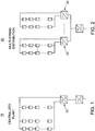
- PV plant architectures take several forms starting from the conventional central inverter system to a fully distributed system as shown in Figures 1-4 , all of which can be considered to have multiple dc-dc power converters.
- Figure 1 illustrates a PV plant architecture 10 that employs a two-stage central inverter 12.
- Figure 2 illustrates a PV plant architecture 20 that employs a string combiner distribution of dc-dc converters 22.
- Figure 3 illustrates a PV plant architecture 30 that employs a string distribution of dc-dc converters 32.
- Figure 4 illustrates a PV plant architecture 40 that employs a module level distribution of dc-dc converters 42.
- Power converters are designed to have high efficiency over a range of its operating power. Maintaining power converter operation within this power range will result in significant energy savings. PV modules are not at their rated power for most of their operating time; therefore the dc-dc converter stage(s) associated with them are always operated at partial load and in many cases at light load. Well-designed power converters have a high efficiency that is relatively constant for a wide load range. Converter losses however, constitute a larger percentage of the input power as this power level becomes smaller and consequently, light load efficiency of these converters fall sharply.
- Distributed PV plant architectures such as described above have benefits in increasing the energy yield of the plant.
- Distributed PV plant architectures provide, for example, more operational flexibility due to the availability of multiple dc-dc or dc-ac converters that can be controlled to operate simultaneously and share the generated power or switched in and out when needed.
- distributed PV plant architectures provide increased energy yield and operational flexibility, they still suffer from reduced power conversion efficiency at partial and/or light loading in PV power plants.
- a string level maximum power point distributed photovoltaic (PV) power plant comprises:
- a method of operating a string level maximum power point distributed photovoltaic (PV) power plant comprises:
- a string level maximum power point distributed photovoltaic (PV) power plant comprises a plurality of distributed dc-dc converters configured to switch in coordination with one another such that at least one dc-dc converter transfers power to a common dc-bus based upon the total system power available from one or more corresponding strings of PV modules, and further such that each dc-dc converter transferring power to the common dc-bus continues to operate within its optimal efficiency range to increase the energy yield of the PV power plant.
- PV photovoltaic
- the embodiments described herein provide increased power conversion efficiency of a solar plant by selectively operating a number of dc-dc converters that is sufficient to handle the power generated by the PV modules while operating in their highest efficiency operating region since each converter will see a higher input power to process than when all converters are operated all the time. Consequently, the individual operational converter efficiency will remain higher for a wider range of total input power.
- PV plant architectures take several forms starting from the conventional central inverter system to a fully distributed system such as described herein with reference to Figures 1-4 . All of the PV plant architectures depicted in Figures 2-4 can be considered to have multiple dc-dc converters. Selective operation of converters becomes inapplicable in the case of module level distribution such as illustrated in Figure 4 because it may result in the total shutdown of an associated module, which contradicts the desired result of maximizing the plant energy yield. Selective operation of converters is otherwise applicable for fully distributed PV plant architectures such as illustrated in Figures 2-3 .
- Dc-dc converters connected to PV strings can be stacked in a string combiner box 52 located at a central location with respect to the strings such as depicted in Figure 5 that illustrates a distributed PV architecture 50 with a single dc-dc converter 54 per string operating with selective converter switching according to one embodiment.
- the power flow is controlled by means of sets of switches 53, which can either be semiconductor devices or mechanical switches.
- the terminals 56 of each string are led to the combiner box 52.
- a sufficient number of dc-dc converters 54 are operated to transfer power to a corresponding dc-bus 58, i.e. for partial loading, some converters 54 are switched out and multiple strings are connected in parallel to feed other converters 54 such as depicted in Figure 5 .
- local controllers 51 operate to ensure proper current sharing between converters 54 when several strings are connected to each operational converter 54.
- the efficiency of a system of string level converters processing partial power with equal current sharing is significantly improved when coordinated switching of the appropriate number of converters 54 is used as compared to independently operating strings of dc-dc converters 54.
- coordinated switching provides an improvement at light loads when compared to a central high power dc-dc converter, which still maintains a slightly higher efficiency at high load conditions.
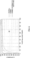
- Figure 6 is a graph 60 illustrating an efficiency comparison between central, distributed dc-dc converters per string and distributed dc-dc converters per string with coordinated switching according to one embodiment that comprises a set of 14 strings, each rated at 3kWp and connected to a string combiner, thus providing a total of 42kWp.
- the results illustrate that string converters with coordinated switching start showing a system efficiency improvement when the PV panels produce less than 50% of their rated power; and this improvement increases significantly as the power is reduced. Further, selectively switched dc-dc converters can be seen to surpass a central dc-dc converter processing this power below about 25% of generation capacity.
- the input power flow to the dc-dc converters is controlled by a number of switches. These switches, which may be mechanical switches or semiconductor switches, can be within or external to the power converter. Converter switches in interleaved topologies such as in Figures 9 and 12 can also be coordinated in a way that controls power flow between the channels of the interleaved dc-dc converters. Control signals for these switches can be provided either through local controllers or a central control unit. In addition to the topologies in Figures 9 and 12 , coordinated switching can be applied in a similar manner to any interleaved dc-dc converter topology with any number of channels.
- team operation of string converters advantageously allows coordination of a global maximum power point (MPPT) search.
- MPPT global maximum power point
- Performing a global MPPT search with a central dc-dc converter causes a significant power drop during the time period of the sweep. This can be transformed into several small power reductions if the MPPT search is performed on individual converters such that overall plant generation is not significantly affected for a plant architecture that employs team operation of string converters.
- a central controller can be used to implement a time shifted global MPPT sweep for all the converters being controlled by the central controller.
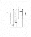
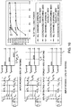
- Figure 7 is a timing diagram 70 illustrating timing of a global MPPT sweep for a plurality of different string converters according to one embodiment.
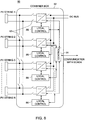
- Figure 8 illustrates coordinated switching string converters with a central controller per combiner box 82 and power flow directing switches 83 according to one embodiment that is suitable for implementing a time shifted global MPPT sweep such as described herein with reference to Figure 7 .
- the desired central control can be implemented on a plant level such as illustrated in Figure 5 according to one embodiment, or can be implemented with a controller 84 placed in each combiner box 82 communicating with local converter controllers 86 such as depicted in Figure 8 .
- Figure 9 illustrates an interleaved buck-boost string dc-dc converter topology 90 that is suitable for use in a coordinated switching process according to one embodiment.
- the switching frequency and the number of operational channels together determine the delay between each channel switching pulses. The result of this operation is the desired higher partial load efficiency characteristic.
- Figure 10 illustrates the operational stages and resulting partial load efficiency characteristic of the interleaved buck-boost string converter 90 depicted in Figure 9 at different levels of input power for a 5.25kW converter split into three channels of 1.75kW power rating.
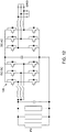
- Figure 11 illustrates a conventional two-stage central PV inverter topology 110.
- Figure 12 illustrates team operation of the dc-dc stage of the two-stage central PV inverter depicted in Figure 11 according to one embodiment. More specifically, the same switching coordination concepts and principles described herein before can be applied to the conventional two-stage central PV inverter topology 110 by systematically choosing how many legs of the input boost converter 120 are operated such that the overall converter efficiency is increased over a wide load range such as illustrated for one embodiment in Figure 13 .
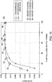
- Figure 13 is a graph 130 illustrating efficiency curves of the dc-dc stage portion for the two-stage central PV inverter with the coordinated switching dc-dc stage 120 depicted in Figure 12 according to one embodiment. Operation of the two-stage central PV inverter using one leg of the dc-dc stage 120, two legs of the dc-dc stage 120 and three legs of the dc-dc stage 120 are shown. The efficiency of the dc-dc stage 120 using switching coordination can be seen to exceed the efficiency of the dc-dc stage 120 using conventional operating techniques for input power below about 70% of the PV plant rated generation.
- Coordinated switching of distributed dc-dc converters advantageously provides a high and constant overall efficiency curve for the dc conversion stage of the PV power plant.
- coordinated switching of distributed dc-dc converters as described herein advantageously allows for coordinated MPPT global searches in a manner such that they do not all coincide at the same time, thus preventing the occurrence of significant dips in the PV plant output power and allowing the individual global searches to be performed in a shorter time.
- the local MPPT search it can either be centralized or made independent for each of the dc-dc converters
- the concepts and principles described herein can be extended to two-stage solar inverters incorporating interleaved or paralleled input dc-dc stages. Further, for PV plants with multi-string dc-dc converters that feed into a central inverter as shown in Figure 2 , the dc-dc converters can also be operated with coordinated switching according to the amount of power being generated by the plant.
- the PV power plant may comprise, without limitation, one or more dc-dc converters and at least one string of PV modules.
- Each dc-dc converter receives power from at least one corresponding string of PV modules.
- At least one dc-dc converter is configured to transfer power to a common dc-bus based upon the total system power available from each corresponding string of PV modules such that each dc-dc converter transferring power to the common dc-bus continues to operate within its optimal efficiency range to increase the energy yield of the PV power plant.
Landscapes
- Engineering & Computer Science (AREA)
- Power Engineering (AREA)
- Direct Current Feeding And Distribution (AREA)
- Dc-Dc Converters (AREA)
- Control Of Electrical Variables (AREA)
- Photovoltaic Devices (AREA)
Applications Claiming Priority (1)
| Application Number | Priority Date | Filing Date | Title |
|---|---|---|---|
| US13/097,196 US8829715B2 (en) | 2011-04-29 | 2011-04-29 | Switching coordination of distributed dc-dc converters for highly efficient photovoltaic power plants |
Publications (2)
| Publication Number | Publication Date |
|---|---|
| EP2518855A2 true EP2518855A2 (de) | 2012-10-31 |
| EP2518855A3 EP2518855A3 (de) | 2013-10-16 |
Family
ID=45819005
Family Applications (1)
| Application Number | Title | Priority Date | Filing Date |
|---|---|---|---|
| EP20120157063 Withdrawn EP2518855A3 (de) | 2011-04-29 | 2012-02-27 | Schaltungskoordinierung verteilter Gleichstrom-Gleichstrom-Umwandler für hocheffiziente photovoltaische Kraftwerke |
Country Status (4)
| Country | Link |
|---|---|
| US (1) | US8829715B2 (de) |
| EP (1) | EP2518855A3 (de) |
| JP (1) | JP2012235677A (de) |
| CN (1) | CN102761294A (de) |
Cited By (4)
| Publication number | Priority date | Publication date | Assignee | Title |
|---|---|---|---|---|
| EP2770539A1 (de) * | 2013-02-20 | 2014-08-27 | Total Marketing Services | Elektronisches Verwaltungssystem für Stromerzeugungszellen, Stromerzeugungssystem und Verfahren zur elektronischen Verwaltung des Energieflusses |
| EP2797196A1 (de) * | 2013-04-25 | 2014-10-29 | Kabushiki Kaisha Yaskawa Denki | Netzkopplungsvorrichtung |
| WO2018162215A1 (en) * | 2017-03-07 | 2018-09-13 | Abb Schweiz Ag | A photovoltaic power plant system |
| WO2019091485A1 (en) * | 2017-11-13 | 2019-05-16 | Huawei Technologies Co., Ltd. | System and device for exporting power, and method of configuring thereof |
Families Citing this family (26)
| Publication number | Priority date | Publication date | Assignee | Title |
|---|---|---|---|---|
| US20130076144A1 (en) * | 2011-09-28 | 2013-03-28 | General Electric Company | System and method for limiting photovoltaic string voltage |
| EP2587334A1 (de) * | 2011-10-24 | 2013-05-01 | Imec | Neukonfigurierbare PV-Konfiguration |
| US8793028B2 (en) * | 2011-11-21 | 2014-07-29 | General Electric Company | System and method for determining potential power of inverters during curtailment mode |
| US10411477B2 (en) * | 2012-03-26 | 2019-09-10 | Pika Energy, Inc. | Distributed substring architecture for maximum power point tracking of energy sources |
| US9389288B2 (en) | 2012-09-14 | 2016-07-12 | General Electric Company | System and method for maintaining soft switching condition in a gradient coil driver circuit |
| CN103872939B (zh) * | 2012-12-18 | 2016-12-28 | 比亚迪股份有限公司 | 一种双路升压电路逆变器系统及其控制方法 |
| JP6191403B2 (ja) * | 2013-01-24 | 2017-09-06 | オムロン株式会社 | パワーコンディショナ、太陽電池システム、および異常判定方法 |
| US9748772B2 (en) | 2013-02-14 | 2017-08-29 | Abb Schweiz Ag | Method of controlling a solar power plant, a power conversion system, a DC/AC inverter and a solar power plant |
| DE102014101809B4 (de) * | 2014-02-13 | 2020-02-20 | Skytron Energy Gmbh | Verfahren zur Steuerung einer regenerativen Energieerzeugungsanlage und Regenerative Energieerzeugungsanlage |
| CN104201885A (zh) * | 2014-09-15 | 2014-12-10 | 浙江昱能科技有限公司 | 光伏系统的优化器及其电力转换电路 |
| US20160079914A1 (en) * | 2014-09-16 | 2016-03-17 | Junbo Wu | Integrated tracker controller |
| JP6211739B1 (ja) * | 2014-09-24 | 2017-10-11 | アーベーベー・シュバイツ・アーゲー | Pvプラントのdc部分における設置エラーを判断するための方法および当該方法を実行するためのdc部分の集電箱 |
| AU2015364718B2 (en) | 2014-12-16 | 2019-11-28 | Marici Holdings The Netherlands B.V. | Energy panel arrangement power dissipation |
| US10348094B2 (en) | 2015-01-28 | 2019-07-09 | Abb Schweiz Ag | Energy panel arrangement shutdown |
| WO2016134356A1 (en) | 2015-02-22 | 2016-08-25 | Abb Technology Ag | Photovoltaic string reverse polarity detection |
| US10027277B2 (en) | 2015-03-25 | 2018-07-17 | Zyntony, Inc. | Short-string parallel-DC optimizer for photovoltaic systems |
| FR3036369B1 (fr) * | 2015-05-18 | 2018-08-24 | Rool'in | Roue de vehicule equipee de cellules solaires |
| CN105141249B (zh) * | 2015-09-15 | 2018-01-12 | 河海大学常州校区 | 一种失配条件下光伏阵列动态组态重构拓扑电路及方法 |
| US20170077709A1 (en) * | 2015-09-15 | 2017-03-16 | Abb Technology Ltd. | Pv system having distributed dc-dc converters |
| US10256732B2 (en) | 2015-10-16 | 2019-04-09 | General Electric Company | Power conversion system and method of operating the same |
| US20170170739A1 (en) * | 2015-12-11 | 2017-06-15 | National Chung-Shan Institute Of Science & Technology | Solar power converter with isolated bipolar full-bridge resonant circuit |
| GB2551753A (en) * | 2016-06-29 | 2018-01-03 | Liu Xiongwei | Apparatus for use in a solar photovoltaic power system and methods of operating the same |
| CN112585835B (zh) * | 2018-08-10 | 2024-07-05 | 维斯塔斯风力系统集团公司 | 混合动力发电厂 |
| EP4708672A2 (de) | 2020-12-31 | 2026-03-11 | Huawei Digital Power Technologies Co., Ltd. | Fotovoltaisches stromerzeugungssystem, fotovoltaischer wechselrichter und gleichstromkombiniererkasten |
| WO2022227083A1 (zh) * | 2021-04-30 | 2022-11-03 | 华为数字能源技术有限公司 | 一种功率变换器盒及光伏系统 |
| JP2023113377A (ja) * | 2022-02-03 | 2023-08-16 | ダイヤゼブラ電機株式会社 | 太陽光発電システム及びパワーコンディショナ |
Family Cites Families (17)
| Publication number | Priority date | Publication date | Assignee | Title |
|---|---|---|---|---|
| JP2001268800A (ja) | 2000-03-16 | 2001-09-28 | Kawasaki Steel Corp | 太陽光発電制御方法及び装置 |
| JP3747313B2 (ja) * | 2000-04-27 | 2006-02-22 | シャープ株式会社 | 系統連系インバータ装置 |
| US7339287B2 (en) | 2002-06-23 | 2008-03-04 | Powerlynx A/S | Power converter |
| JP4776348B2 (ja) | 2005-11-11 | 2011-09-21 | シャープ株式会社 | インバータ装置 |
| EP2025051B1 (de) | 2006-06-06 | 2014-12-31 | Ideal Power Inc. | Universeller stromrichter |
| US7787270B2 (en) * | 2007-06-06 | 2010-08-31 | General Electric Company | DC-DC and DC-AC power conversion system |
| CN101904073B (zh) | 2007-10-15 | 2014-01-08 | Ampt有限公司 | 高效太阳能电力系统 |
| JP2009148149A (ja) * | 2007-11-20 | 2009-07-02 | Nissin Electric Co Ltd | 昇降圧チョッパ回路の制御方法 |
| US9263895B2 (en) * | 2007-12-21 | 2016-02-16 | Sunpower Corporation | Distributed energy conversion systems |
| CN101488668A (zh) * | 2008-04-30 | 2009-07-22 | 江苏南自通华新能源电力有限公司 | 可重构分布式接入并网逆变器 |
| JP5297836B2 (ja) | 2009-02-20 | 2013-09-25 | シャープ株式会社 | 発電システム |
| US9442504B2 (en) | 2009-04-17 | 2016-09-13 | Ampt, Llc | Methods and apparatus for adaptive operation of solar power systems |
| CN101867291A (zh) * | 2009-04-17 | 2010-10-20 | 吕斌 | 户用太阳能光伏逆变器 |
| JP5302096B2 (ja) * | 2009-05-15 | 2013-10-02 | 株式会社Nttファシリティーズ | 太陽光発電システム及び制御方法 |
| EP2280469B1 (de) * | 2009-07-30 | 2016-07-06 | Nxp B.V. | Photovoltaische Einheit, Gleichstromwandler dafür und Verfahren zu deren Betrieb |
| CN101702523B (zh) * | 2009-11-20 | 2011-08-24 | 南京航空航天大学 | 一种分布式模块化并网发电系统的控制方法 |
| KR101097260B1 (ko) * | 2009-12-15 | 2011-12-22 | 삼성에스디아이 주식회사 | 계통 연계형 전력 저장 시스템 및 전력 저장 시스템 제어 방법 |
-
2011
- 2011-04-29 US US13/097,196 patent/US8829715B2/en active Active
-
2012
- 2012-02-23 JP JP2012036902A patent/JP2012235677A/ja not_active Ceased
- 2012-02-27 EP EP20120157063 patent/EP2518855A3/de not_active Withdrawn
- 2012-02-29 CN CN2012100603512A patent/CN102761294A/zh active Pending
Non-Patent Citations (1)
| Title |
|---|
| None |
Cited By (9)
| Publication number | Priority date | Publication date | Assignee | Title |
|---|---|---|---|---|
| EP2770539A1 (de) * | 2013-02-20 | 2014-08-27 | Total Marketing Services | Elektronisches Verwaltungssystem für Stromerzeugungszellen, Stromerzeugungssystem und Verfahren zur elektronischen Verwaltung des Energieflusses |
| WO2014128202A1 (en) * | 2013-02-20 | 2014-08-28 | Total Marketing Services | Electronic management system for electricity generating cells, electricity generating system and method for electronically managing energy flow |
| EP2797196A1 (de) * | 2013-04-25 | 2014-10-29 | Kabushiki Kaisha Yaskawa Denki | Netzkopplungsvorrichtung |
| WO2018162215A1 (en) * | 2017-03-07 | 2018-09-13 | Abb Schweiz Ag | A photovoltaic power plant system |
| EP3373433B1 (de) * | 2017-03-07 | 2020-04-29 | ABB Schweiz AG | Eine photovoltaik-stromerzeugungsanlage |
| US11228178B2 (en) | 2017-03-07 | 2022-01-18 | Marici Holdings The Netherlands B.V. | Photovoltaic power plant system |
| WO2019091485A1 (en) * | 2017-11-13 | 2019-05-16 | Huawei Technologies Co., Ltd. | System and device for exporting power, and method of configuring thereof |
| US10673246B2 (en) | 2017-11-13 | 2020-06-02 | Futurewei Technologies, Inc. | System and device for exporting power, and method of configuring thereof |
| US11515709B2 (en) | 2017-11-13 | 2022-11-29 | Huawei Digital Power Technologies Co., Ltd. | System and device for exporting power, and method of configuring thereof |
Also Published As
| Publication number | Publication date |
|---|---|
| US20120274139A1 (en) | 2012-11-01 |
| EP2518855A3 (de) | 2013-10-16 |
| JP2012235677A (ja) | 2012-11-29 |
| CN102761294A (zh) | 2012-10-31 |
| US8829715B2 (en) | 2014-09-09 |
Similar Documents
| Publication | Publication Date | Title |
|---|---|---|
| US8829715B2 (en) | Switching coordination of distributed dc-dc converters for highly efficient photovoltaic power plants | |
| US20240332434A1 (en) | Refined Solar Panel String Converter Topology | |
| US20230084452A1 (en) | Enhanced system and method for string balancing | |
| EP2475061B1 (de) | Steuergerät-Anordnung für ein elektrisches Stromübertragungssystem einer Windturbine | |
| CN103346673B (zh) | 一种多路并联的dc-dc变换器控制系统及方法 | |
| US11720135B2 (en) | Systems and methods for quick dissipation of stored energy from input capacitors of power inverters | |
| EP2773036B1 (de) | Verfahren zur Gleichstrom-Wechselstrom-Umwandlung | |
| US10651735B2 (en) | Series stacked DC-DC converter with serially connected DC power sources and capacitors | |
| US20160344192A1 (en) | Systems and methods for quick dissipation of stored energy from input capacitors of power inverters | |
| JP2013536512A (ja) | 電源から電力を抽出するためのスイッチング回路および関連方法 | |
| WO2014121826A1 (en) | Solar power plant, method of controlling a solar power plant and a dc/dc conversion system | |
| WO2011008944A4 (en) | Smart and scalable power inverters | |
| CN103119840B (zh) | 双向dc调节器 | |
| Agamy et al. | Dc-dc converter topology assessment for large scale distributed photovoltaic plant architectures | |
| CN117751500A (zh) | 一种光伏功率转换装置 | |
| CN113364025A (zh) | 风力发电单元、海上送端换流站、输电系统及输电方法 | |
| CN106505945B (zh) | 用于操作光伏系统的方法 | |
| WO2013098844A2 (en) | Grid tie inverter | |
| KR20230005700A (ko) | 멀티레벨 구조를 가지는 전력변환장치 |
Legal Events
| Date | Code | Title | Description |
|---|---|---|---|
| PUAI | Public reference made under article 153(3) epc to a published international application that has entered the european phase |
Free format text: ORIGINAL CODE: 0009012 |
|
| AK | Designated contracting states |
Kind code of ref document: A2 Designated state(s): AL AT BE BG CH CY CZ DE DK EE ES FI FR GB GR HR HU IE IS IT LI LT LU LV MC MK MT NL NO PL PT RO RS SE SI SK SM TR |
|
| AX | Request for extension of the european patent |
Extension state: BA ME |
|
| RIC1 | Information provided on ipc code assigned before grant |
Ipc: H02J 3/38 20060101AFI20130415BHEP Ipc: H02M 3/158 20060101ALI20130415BHEP |
|
| PUAL | Search report despatched |
Free format text: ORIGINAL CODE: 0009013 |
|
| AK | Designated contracting states |
Kind code of ref document: A3 Designated state(s): AL AT BE BG CH CY CZ DE DK EE ES FI FR GB GR HR HU IE IS IT LI LT LU LV MC MK MT NL NO PL PT RO RS SE SI SK SM TR |
|
| AX | Request for extension of the european patent |
Extension state: BA ME |
|
| RIC1 | Information provided on ipc code assigned before grant |
Ipc: H02J 3/38 20060101AFI20130906BHEP Ipc: H02M 3/158 20060101ALI20130906BHEP |
|
| 17P | Request for examination filed |
Effective date: 20140416 |
|
| RBV | Designated contracting states (corrected) |
Designated state(s): AL AT BE BG CH CY CZ DE DK EE ES FI FR GB GR HR HU IE IS IT LI LT LU LV MC MK MT NL NO PL PT RO RS SE SI SK SM TR |
|
| STAA | Information on the status of an ep patent application or granted ep patent |
Free format text: STATUS: THE APPLICATION IS DEEMED TO BE WITHDRAWN |
|
| 18D | Application deemed to be withdrawn |
Effective date: 20170901 |