EP2519030A1 - Capteur acoustique et microphone - Google Patents
Capteur acoustique et microphone Download PDFInfo
- Publication number
- EP2519030A1 EP2519030A1 EP11770990A EP11770990A EP2519030A1 EP 2519030 A1 EP2519030 A1 EP 2519030A1 EP 11770990 A EP11770990 A EP 11770990A EP 11770990 A EP11770990 A EP 11770990A EP 2519030 A1 EP2519030 A1 EP 2519030A1
- Authority
- EP
- European Patent Office
- Prior art keywords
- diaphragm
- acoustic sensor
- slit
- acoustic
- sensor according
- Prior art date
- Legal status (The legal status is an assumption and is not a legal conclusion. Google has not performed a legal analysis and makes no representation as to the accuracy of the status listed.)
- Granted
Links
Images


Classifications
-
- G—PHYSICS
- G01—MEASURING; TESTING
- G01H—MEASUREMENT OF MECHANICAL VIBRATIONS OR ULTRASONIC, SONIC OR INFRASONIC WAVES
- G01H11/00—Measuring mechanical vibrations or ultrasonic, sonic or infrasonic waves by detecting changes in electric or magnetic properties
-
- H—ELECTRICITY
- H04—ELECTRIC COMMUNICATION TECHNIQUE
- H04R—LOUDSPEAKERS, MICROPHONES, GRAMOPHONE PICK-UPS OR LIKE ACOUSTIC ELECTROMECHANICAL TRANSDUCERS; ELECTRIC HEARING AIDS; PUBLIC ADDRESS SYSTEMS
- H04R19/00—Electrostatic transducers
- H04R19/005—Electrostatic transducers using semiconductor materials
-
- G—PHYSICS
- G01—MEASURING; TESTING
- G01H—MEASUREMENT OF MECHANICAL VIBRATIONS OR ULTRASONIC, SONIC OR INFRASONIC WAVES
- G01H15/00—Measuring mechanical or acoustic impedance
-
- H—ELECTRICITY
- H04—ELECTRIC COMMUNICATION TECHNIQUE
- H04R—LOUDSPEAKERS, MICROPHONES, GRAMOPHONE PICK-UPS OR LIKE ACOUSTIC ELECTROMECHANICAL TRANSDUCERS; ELECTRIC HEARING AIDS; PUBLIC ADDRESS SYSTEMS
- H04R19/00—Electrostatic transducers
- H04R19/04—Microphones
-
- H—ELECTRICITY
- H04—ELECTRIC COMMUNICATION TECHNIQUE
- H04R—LOUDSPEAKERS, MICROPHONES, GRAMOPHONE PICK-UPS OR LIKE ACOUSTIC ELECTROMECHANICAL TRANSDUCERS; ELECTRIC HEARING AIDS; PUBLIC ADDRESS SYSTEMS
- H04R1/00—Details of transducers, loudspeakers or microphones
- H04R1/02—Casings; Cabinets ; Supports therefor; Mountings therein
- H04R1/04—Structural association of microphone with electric circuitry therefor
-
- H—ELECTRICITY
- H04—ELECTRIC COMMUNICATION TECHNIQUE
- H04R—LOUDSPEAKERS, MICROPHONES, GRAMOPHONE PICK-UPS OR LIKE ACOUSTIC ELECTROMECHANICAL TRANSDUCERS; ELECTRIC HEARING AIDS; PUBLIC ADDRESS SYSTEMS
- H04R1/00—Details of transducers, loudspeakers or microphones
- H04R1/06—Arranging circuit leads; Relieving strain on circuit leads
-
- H—ELECTRICITY
- H04—ELECTRIC COMMUNICATION TECHNIQUE
- H04R—LOUDSPEAKERS, MICROPHONES, GRAMOPHONE PICK-UPS OR LIKE ACOUSTIC ELECTROMECHANICAL TRANSDUCERS; ELECTRIC HEARING AIDS; PUBLIC ADDRESS SYSTEMS
- H04R2410/00—Microphones
- H04R2410/03—Reduction of intrinsic noise in microphones
-
- H—ELECTRICITY
- H04—ELECTRIC COMMUNICATION TECHNIQUE
- H04R—LOUDSPEAKERS, MICROPHONES, GRAMOPHONE PICK-UPS OR LIKE ACOUSTIC ELECTROMECHANICAL TRANSDUCERS; ELECTRIC HEARING AIDS; PUBLIC ADDRESS SYSTEMS
- H04R7/00—Diaphragms for electromechanical transducers; Cones
- H04R7/02—Diaphragms for electromechanical transducers; Cones characterised by the construction
- H04R7/04—Plane diaphragms
- H04R7/06—Plane diaphragms comprising a plurality of sections or layers
-
- H—ELECTRICITY
- H10—SEMICONDUCTOR DEVICES; ELECTRIC SOLID-STATE DEVICES NOT OTHERWISE PROVIDED FOR
- H10W—GENERIC PACKAGES, INTERCONNECTIONS, CONNECTORS OR OTHER CONSTRUCTIONAL DETAILS OF DEVICES COVERED BY CLASS H10
- H10W70/00—Package substrates; Interposers; Redistribution layers [RDL]
- H10W70/60—Insulating or insulated package substrates; Interposers; Redistribution layers
- H10W70/67—Insulating or insulated package substrates; Interposers; Redistribution layers characterised by their insulating layers or insulating parts
- H10W70/68—Shapes or dispositions thereof
- H10W70/681—Shapes or dispositions thereof comprising holes not having chips therein, e.g. for outgassing, underfilling or bond wire passage
-
- H—ELECTRICITY
- H10—SEMICONDUCTOR DEVICES; ELECTRIC SOLID-STATE DEVICES NOT OTHERWISE PROVIDED FOR
- H10W—GENERIC PACKAGES, INTERCONNECTIONS, CONNECTORS OR OTHER CONSTRUCTIONAL DETAILS OF DEVICES COVERED BY CLASS H10
- H10W90/00—Package configurations
- H10W90/701—Package configurations characterised by the relative positions of pads or connectors relative to package parts
- H10W90/751—Package configurations characterised by the relative positions of pads or connectors relative to package parts of bond wires
- H10W90/753—Package configurations characterised by the relative positions of pads or connectors relative to package parts of bond wires between laterally-adjacent chips
Definitions
- the present invention relates to an acoustic sensor and a microphone. Specifically, the present invention relates to an acoustic sensor of a capacitance type, manufactured by means of a MEMS (Micro Electro Mechanical System) technique or micromachining technique. Further, the present invention relates to a microphone using the acoustic sensor.
- MEMS Micro Electro Mechanical System
- a method for increasing an S/N ratio of the acoustic sensor first, there is a method of increasing sensitivity of the acoustic sensor.
- a method of widening an area of a diaphragm In order to increase the sensitivity of the acoustic sensor of the capacitance type, there can be adopted a method of widening an area of a diaphragm and a method of reducing spring properties of the diaphragm to increase a displacement amount of the diaphragm.
- the former method of widening the area of the diaphragm reduction in size of the acoustic sensor is hindered.
- a method of decreasing the spring properties of the diaphragm since the displacement amount of the diaphragm increases, durability of the acoustic sensor decreases.
- a second method for increasing the S/N ratio of the acoustic sensor is to reduce noise of the acoustic sensor.
- the noise of the acoustic sensor of the capacitance type thermal noise generated in an air gap formed between the diaphragm (movable electrode plate) and a back plate (fixed electrode plate) are problematical.
- the thermal noise in the air gap is noise generated by a mechanism shown in Fig. 1(A) .
- air molecules ⁇ present inside an air gap 13 between a diaphragm 11 and a back plate 12, namely a semi-enclosed space are collided with the diaphragm 11 due to fluctuations (thermal motion).
- Microforce due to the collision with the air molecules ⁇ is applied to the diaphragm 11, and the microforce applied to the diaphragm 11 fluctuates at random. Therefore, the diaphragm 11 vibrates due to the collision with the air molecules ⁇ , to generate electric noise in a vibration sensor.
- noise attributed to such thermal noise is large, and the S/N ratio thus deteriorates.
- the noise attributed to such thermal noise is alleviated by increasing an opening ratio of an acoustic hole 14 opened in the back plate 12 as shown in Fig. 1 (B) , to facilitate passage of air inside the air gap 13 through the acoustic hole 14. Further, the noise is also alleviated by widening the air gap 13 between the diaphragm 11 and the back plate 12.
- a capacitance of a capacitor configured by the diaphragm 11 and the back plate 12 decreases. For this reason, with the method of simply reducing noise, the sensitivity of the acoustic sensor decreases simultaneously with reduction in noise, and hence it has not been possible to improve the S/N ratio of the acoustic sensor.
- Patent Document 1 discloses a microphone of a difference sensing system aimed at improving the S/N ratio.
- this microphone 21 as shown in Fig. 2 , two acoustic sensors 23a, 23b are provided on one substrate 22, and vertical configurations of both sensors 23a, 23b are inverted to each other. That is, in one acoustic sensor 23a, a fixed plate 25a having acoustic holes 26a is formed above a diaphragm 24a, to constitute a capacitor for acoustic sensing. In the other acoustic sensor 23b, a diaphragm 24b is formed above a fixed plate 25b having acoustic holes 26b, to constitute a capacitor for acoustic sensing.
- sensing signals outputted from the diaphragms 24a, 24b in the acoustic sensors 23a, 23b when both acoustic sensors 23a, 23b detect the same acoustic vibration, sensing signals with phases displaced 180° are outputted from both sensors 23a, 23b.
- the output of the acoustic sensor 23a and the output of the acoustic sensor 23b are inputted into a signal processing circuit (ASIC), and subjected to subtraction processing inside the signal processing circuit. This results in adding up of the acoustic detection signals detected by both sensors 23a, 23b, whereby the detection sensitivity of the microphone 21 improves, and the S/N ratio is expected to improve.
- ASIC signal processing circuit
- Patent Document 2 discloses another conventional microphone.
- This microphone 31 basically has a similar structure to that of the microphone 21 of Patent Document 1.
- a plurality of independent acoustic sensors 33a, 33b, ... having the same structure are provided on a common substrate 32. That is, any of the acoustic sensors 33a, 33b, ... is formed with a diaphragm 34 as opposed to the top surface of a fixed plate 35 in which acoustic holes 36 are opened.
- a signal processing circuit 37 is provided on the top surface of the substrate 32, and an output of each of the acoustic sensors 33a, 33b, ...
- the output of each of the acoustic sensors 33a, 33b, ... is subjected to addition processing in the signal processing circuit 37 so that the improvement in S/N ratio is expected.
- each sensor since the plurality of independent acoustic sensors are provided, disagreement of the acoustic characteristics other than the sensitivity tend to occur among each sensor. For example, since the frequency characteristics, phases and the like are influenced by a back chamber and a vent hole, each sensor tends to have different characteristics.
- the plurality of independent acoustic sensors need to be arranged in array on the substrate, there has been a problem of the microphone being not reducible in size.
- the present invention was made in view of the technical problems as described above, and has an object to provide an acoustic sensor capable of improving an S/N ratio of a sensor without preventing reduction in size of the sensor, and a microphone using the acoustic sensor.
- An acoustic sensor of the present invention is an acoustic sensor including: a substrate, having a hollow section; a thin film-like diaphragm, arranged above the substrate so as to cover the hollow section; a movable electrode plate, formed on the diaphragm; a back plate, fixed to the top surface of the substrate so as to be opposed to the diaphragm; and a fixed electrode plate, provided on the back plate in a position opposed to the movable electrode plate, characterized in that the diaphragm and the movable electrode plate are substantially divided into a plurality of areas, and a plurality of parallelly connected capacitors are configured by the respective divided movable electrode plates and the fixed electrode plate.
- the movable electrode plate may be provided on the diaphragm, or the diaphragm itself may serve as a movable electrode plate.
- the diaphragm is only substantially divided into the plurality of areas, the capacitance and the sensitivity with respect to the acoustic vibration remain substantially unchanged from those before division of the diaphragm. Meanwhile, since each divided area of the diaphragm can move almost independently, each area is displaced in an independent and discontinuous manner with respect to thermal noise, and when noise in each area is added up, the noise cancels one another, so as to be reduced. This results in improvement in S/N ratio of the acoustic sensor. Furthermore, the diaphragm is divided into the plurality of areas to perform acoustic detection in each area, thereby not preventing reduction in size of the acoustic sensor.
- One embodiment of the acoustic sensor according to the present invention has a feature in that the diaphragm and the movable electrode plate are divided by the slit.
- the opening in the diaphragm and the movable electrode plate becomes wider, air tends to leak through the diaphragm and the movable electrode plate, leading to deterioration in low-frequency characteristics of the acoustic sensor.
- the opening for dividing the diaphragm and the movable electrode plate can be made narrow, so as to prevent deterioration in low-frequency characteristics of the acoustic sensor and prevent a decrease in sensitivity thereof.
- Another embodiment of the acoustic sensor formed with the slit has a feature in that the slit is formed in a position passing through a maximal displacement place of the diaphragm.
- the slit is provided so as to pass through the maximal displacement place of the diaphragm, it is possible to increase the S/N ratio improving effect of the acoustic sensor.
- Still another embodiment of the acoustic sensor formed with the slit has a feature in that the respective areas of the diaphragm divided by the slit respectively have the maximal displacement places with the slit provided therebetween.
- the respective areas of the divided diaphragm respectively have the maximal displacement places with the slit provided therebetween it is possible to increase the S/N ratio improving effect of the acoustic sensor.
- Yet another embodiment of the acoustic sensor formed with the slit has a feature in that the slit is located on a line segment connecting any two supporting places out of supporting places of the diaphragm.
- the slit is formed on the line segment connecting the supporting places of the diaphragm, a displacement of the end of the slit can be made small so that a stress concentration at the end of the slit can be made small.
- the slit may be partially interrupted, and the respective areas of the diaphragm, which are located on both sides of the slit with the slit provided therebetween, may be partially connected to each other through the interrupted portion of the slit.
- Yet another embodiment of the acoustic sensor formed with the slit has a feature in that the width of the slit is not larger than 10 ⁇ m.
- a roll-off frequency may become as high as 500 Hz to cause deterioration in low-frequency characteristics, and hence the width of the slit is desirably not larger than 10 ⁇ m as in this embodiment.
- Yet another embodiment of the acoustic sensor formed with the slit has a feature in that a length of the slit is not smaller than a half of a distance across length of the diaphragm in an extending direction of the slit.
- a length of the slit is shorter than a half of the width of the diaphragm, discontinuity of the displacement among each area of the diaphragm divided by the slit is impaired, and the effect of reducing noise as a whole deteriorates, whereby the length of the slit is desirably not smaller than a half of the distance across length of the diaphragm in the extending direction of the slit.
- the shape of the diaphragm is not particularly restricted in the acoustic sensor according to the present invention, the diaphragm in circular form or rectangular form is desirably used in terms of the characteristics of the acoustic sensor.
- Yet another embodiment of the acoustic sensor according to the present invention has a feature in that an edge of the diaphragm is supported by the substrate or the back plate at a plurality of supporting places, and a void is provided in at least one place between the adjacent supporting places out of the supporting places.
- Yet another embodiment of the acoustic sensor according to the present invention has a feature in that an acoustic vibration reaches the diaphragm through the hollow section.
- a volume of the back chamber can be made large, so as to improve the sensitivity of the acoustic sensor.
- a microphone according to the present invention is a microphone provided with: the acoustic sensor according to the present invention; and a circuit for processing a signal outputted from the acoustic sensor.
- the microphone of the present invention using the acoustic sensor of the present invention, it is possible to improve the S/N ratio of the microphone.
- the means for solving the above problems in the present invention has features in appropriate combination of the above described constitutional elements, and the present invention enables a large number of variations by combination of such constitutional elements.
- FIG. 4 is a sectional view showing an acoustic sensor 41 of Embodiment 1.
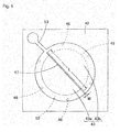
- Fig. 5 is a plan view of the acoustic sensor 41.
- Fig. 6 is a plan view showing a state where a canopy section 44 has been removed from the acoustic sensor 41.
- This acoustic sensor 41 is a capacitance type element produced through use of the MEMS technique. As shown in Fig. 4 , in the acoustic sensor 41, a diaphragm 43 (vibration electrode plate) is provided on the top surface of a silicon substrate 42 (semiconductor substrate) via an anchor 46, and to the top thereof, the canopy section 44 is fixed via a minute air gap 50 (void).
- a diaphragm 43 vibration electrode plate
- a back chamber 45 (hollow section) penetrating from the front surface to the back surface is opened.
- the inner peripheral surface of the back chamber 45 may be a vertical surface or be inclined in taper form.
- a plurality of anchors 46 for supporting the under surface of an outer edge of a diaphragm 43 are provided at almost regular intervals on the top surface of the silicon substrate 42. Further, on the top surface of the silicon substrate 42, a base section 51 is formed so as to surround the diaphragm 43.
- the anchor 46 and the base section 51 are formed of SiO 2 .
- the diaphragm 43 is formed in substantially circular form.
- the diaphragm 43 is formed of a polysilicon thin film having conductivity, and the diaphragm 43 itself serves as a movable electrode plate.
- the diaphragm 43 is arranged on the silicon substrate 42 so as to cover a space above the back chamber 45, and supported by the anchors 46 at almost regular intervals on the silicon substrate 42. Therefore, the diaphragm 43 is supported in the air, and between the adjacent anchors 46, a narrow vent hole 52 for allowing passage of an acoustic vibration is formed between the lower surface of the outer periphery of the diaphragm 43 and the top surface of the silicon substrate 42. Further, a strip-like leading wire 53 is extended outward from the diaphragm 43.
- the diaphragm 43 In the case of fixing a whole perimeter of the diaphragm 43 to the silicon substrate 42, binding force of the diaphragm 43 becomes stronger, leading to an increase in spring properties of the diaphragm 43 and a decrease in sensitivity of the acoustic sensor 41. For this reason, the diaphragm 43 is supported by the anchors 46 at regular intervals, to form the vent hole 52 (void) between each of the anchors 46, as described above.
- the diaphragm 43 is uniformly divided into two portions by a linear slit 47 with a small width positioned so as to pass through the center as the maximal displacement place of the diaphragm 43. However, this is not that the diaphragm 43 is completely divided into two portions by the slit 47, but those are mechanically and electrically connected in the vicinity of the end of the slit 47.
- diaphragms 43a, 43b two areas that are in semicircular form of the diaphragm 43 divided by the slit 47. Both diaphragms 43a, 43b are formed in an identical shape with an identical size.
- the canopy section 44 is formed by providing a fixed electrode plate 49 made of polysilicon on the under surface of the back plate 48 (fixed film) made of SiN.
- the canopy section 44 is formed in dorm form, having a hollow portion therebelow and covering the diaphragm 43 with the hollow portion.
- the minute air gap 50 (void) is formed between the under surface of the canopy section 44 (i.e., the under surface of the fixed electrode plate 49) and the top surface of the diaphragm 43.
- the fixed electrode plate 49 and the diaphragm 43 are opposed to each other, to constitute a capacitor.
- a large number of acoustic holes 54 for allowing passage of an acoustic vibration are punched so as to penetrate from the top surface to the under surface.
- the acoustic holes 54 are regularly arrayed.
- the acoustic holes 54 are arrayed in triangular form along three directions forming angles of 120° with respect to one another, but the holes may be arranged in rectangular form, concentric form or some other form.
- a minute stopper 55 in columnar form protrudes from the under surface of the canopy section 44.
- the stopper 55 protrudes integrally from the under surface of the back plate 48, and penetrates the fixed electrode plate 49 to protrude from the under surface of the canopy section 44.
- the stopper 55 has insulating properties since being made of SiN as is the back plate 48. This stopper 55 is one to prevent the diaphragm 43 from adhering to the fixed electrode plate 49 and not being separated therefrom due to electrostatic force.
- a protective film 56 is continuously extended from the whole of the outer edge of the canopy-like back plate 48.
- the protective film 56 covers the base section 51 and an area on the outside thereof.
- the leading wire 53 is fixed to the base section 51, and a leading wire 57 extracted from the fixed electrode plate 49 is also fixed to the top surface of the base section 51.
- the protective film 56 is formed with an opening, through which a movable-side electrode pad 58 is formed on the top surface of the leading wire 53, and the movable-side electrode pad 58 is conducted to the diaphragm 43 through the leading wire 53.
- a fixed-side electrode pad 59 provided on the top surface of the back plate 48 is conducted to the leading wire 57 via a through hole or the like, and conducted further to the fixed electrode plate 49.
- the diaphragm 43 is divided into two portions, the diaphragm 43a and the diaphragm 43b.
- one acoustic sensing section 60a is configured by a capacitor made up of the diaphragm 43a and an area of the fixed electrode plate 49 which is opposed to the diaphragm 43a.
- the other acoustic sensing section 60b is configured by a capacitor made up of the diaphragm 43b and an area of the fixed electrode plate 49 which is opposed to the diaphragm 43b.
- both sensing sections 60a, 60b are integrally formed in the same place inside the canopy section 44, and have the same configuration, the same shape and the same size, substantially having identical characteristics.
- this acoustic sensor 41 when an acoustic vibrations passes through the acoustic holes 54 and enters the air gap 50 inside the canopy section 44, the diaphragms 43a, 43b as the thin films vibrate with the same phase by the acoustic vibration.
- the diaphragms 43a, 43b vibrate and a gap distance between each of the diaphragms 43a, 43b and the fixed electrode plate 49 changes, a capacitance of each of the sensing sections 60a, 60b changes.
- the diaphragm 43a and the diaphragm 43b are electrically conducted to each other, and the fixed electrode plate 49 is common therebetween. Furthermore, the acoustic sensing sections 60a, 60b are provided in the same position on the substrate 42, and both sensing sections 60a, 60b sense an acoustic vibration with the same phase. For this reason, even with the diaphragms 43a, 43b separated from each other by the slit 47, the capacitance and the sensitivity of the acoustic sensor 41 with respect to an acoustic vibration remain substantially unchanged from those before formation of the slit 47.
- the diaphragms 43a, 43b can be discontinuously displaced on both side of the slit 47.
- thermal noise generated in the acoustic sensing section 60a and thermal noise generated in the acoustic sensing section 60b are sensed as signals with different phases. Therefore, when the noise of each of the sensing sections 60a, 60b is added up, the noise cancels one another, so as to be reduced. This results in improvement in S/N ratio of the acoustic sensor 41.
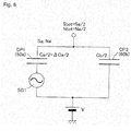
- Fig. 7 represents an equivalent circuit obtained by simplifying the acoustic sensor 41.
- the two acoustic sensing sections 60a, 60b separated by the slit 47 is denoted by two parallelly connected variable capacitors CP1, CP2.
- the two variable capacitors GP1, CP2 have the same performance.
- signal generating sources for an acoustic vibration, noise and the like are represented by alternators SG1, SG2 which are serially connected to the variable capacitors CP1, CP2, respectively.
- the acoustic sensing section 60a is represented by a circuit serially connecting the variable capacitor CP1 and the alternator SG1
- the acoustic sensing section 60b is represented by a circuit serially connecting the variable capacitor CP2 and the alternator SG2.
- the acoustic sensor 41 is represented by an equivalent circuit parallelly connecting both serial-connection circuits.
- the alternator SG2 of the acoustic sensing section 60b is omitted, and it is considered that the capacitance of the variable capacitor CP1 remains unchanged.
- the capacitor CP2 of the acoustic sensing section 60b parallelly connected to the acoustic sensing section 60a acts as a parasitic capacitance on the acoustic sensing section 60a, to alleviate the sensitivity of the acoustic sensing section 60a.
- a sensitivity output Stot made from the acoustic sensor 41 (i.e., a sensitivity output inputted into the signal processing circuit) is reduced into half as expressed in the following formula.
- a noise output Ntot made from the acoustic sensor 41 is expressed by the following formula as a noise output Nb of the acoustic sensing section 60b is reduced into half.
- the sensitivity outputs Sa, Sb and the noise outputs Na, Nb are simultaneously generated in the acoustic sensing sections 60a, 60b, as shown in Fig. 7 .
- the sensitivity output and the noise output are separately considered.
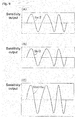
- the sensitivity output with the respective diaphragms 43a, 43b sensing the acoustic vibration arranged in highly proximate positions inside the same canopy section 44, both diaphragms 43a, 43b are vibrating with the same phase and amplitude at the same time.
- the variable capacitor CP1 of the acoustic sensing section 60a and the variable capacitor CP2 of the acoustic sensing section 60b are parallelly connected to each other.
- the sensitivity output Stot of the acoustic sensor 41 is obtained as the sum of the sensitivity outputs Sa/2, Sb/2 of the respective acoustic sensing sections 60a, 60b, having been obtained above.
- Stot Sa / 2 + Sb / 2
- Stot Sa ( Fig. 9(C) ) in the acoustic sensor 41, and indicates that, even by provision of the slit 47, the sensitivity output Stot of the acoustic sensor 41 remains unchanged from that before provision of the slit 47.
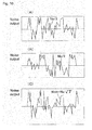
- noise is derived from thermal noise
- noise of the acoustic sensing section 60a and noise of the acoustic sensing section 60b serve as independent signals with nonuniform phases and amplitudes, as shown in Figs. 10(A) and 10(B) .
- Figs. 10(A) and 10(B) show independent signals with nonuniform phases and amplitudes.
- Na Nb
- the sensitivity output Stot of the acoustic sensor 41 is obtained by addition and the noise output Ntot thereof is obtained by calculation at the time of performing an addition of dispersions.
- the S/N ratio of the acoustic sensor 41 is ⁇ (2)Sa/Na, and as compared with the case of the slit 47 being not provided, the S/N ratio becomes ⁇ (2) times as large (or improves by 3dB).
- the noise output decreased by 3dB due to provision of the slit 47. Therefore, the S/N ratio increased by + 3dB by provision of the slit 47.
- the S/N ratio of the acoustic sensor 41 can be improved by provision of the slit 47 in the diaphragm 43.
- a length L (see Fig. 6 ) of the slit 47 desirably crosses not less than 50% of the width of the diaphragm 43. That is, the length L of the slit 47 is desirably a length not smaller than a half of the width of the diaphragm 43 on a line as extension of the slit 47.
- the slit 47 is provided for the purpose of isolating a displacement on the diaphragm 43a side and a displacement on the diaphragm 43b side from each other so as to make them discontinuous, and if the length L of the slit 47 is smaller than a half of the width of the diaphragm 43, the discontinuity of the displacements on the diaphragm 43a side and the diaphragm 43b side is impaired.
- a width W (see Fig. 6 ) of the slit 47 is desirably not larger than 10 ⁇ m. This is because, if the width W of the slit 47 is excessively large, an amount of air, which passes through the slit 47 and leaks to the back chamber 45 through the air gap 50, increases and the roll-off frequency increases, leading to deterioration in low-frequency characteristics of the acoustic sensor 41.
- the roll-off frequency Froll-off is a frequency at the moment of decrease in sensitivity output by given dB on the low frequency side as shown in Fig. 11 .
- Froll - off ⁇ 1 / Rventholl ⁇ Cbackchamber Therefore, when the width W of the slit 47 increases, the acoustic resistance Rventhole decreases and the roll-off frequency Froll-off increases, leading to deterioration in low-frequency characteristics of the acoustic sensor 41.
- the roll-off frequency Froll-off is not larger than 50 Hz when the width W of the slit 47 is 1 ⁇ m, and the roll-off frequency Froll-off is 500 Hz when the width of the slit 47 is 10 ⁇ m.
- the width W of the slit 47 is desirably not larger than 10 ⁇ m.
- total force of pressure applied to each portion of the diaphragm due to thermal noise acts on the maximal displacement place of the diaphragm when the diaphragm has rigidity. Since the maximal displacement place of the diaphragm 43 before formation of the slit 47 is located at the center thereof, it is desirable that the slit 47 be formed so as to pass through the center of the diaphragm 43 and the respective divided diaphragms 43a, 43b have the maximal displacement places on both sides of the slit 47 with the slit provided therebetween.
- Embodiment 1 above as the most preferable embodiment, it has been configured such that the diaphragms 43a, 43b have the same shape and size, and the acoustic sensing sections 60a, 60b substantially have the same characteristics.
- the present invention is not necessarily restricted to such an embodiment, but the diaphragms 43a, 43b may have different shapes or different sizes and the acoustic sensing sections 60a, 60b may have different characteristics.
- Fig. 12 is a plan view of an acoustic sensor 61 according to Embodiment 2 of the present invention.
- Fig. 13 is a plan view of the acoustic sensor 61 in a state where the canopy section 44 has been removed.
- a plurality of (three in the illustrative example) slits 47 are provided in the diaphragm 43, to divide the diaphragm 43 into not less than three areas (four areas in the illustrative example) so as to provide a plurality of substantially independent diaphragms 43a, 43b, .... Then, each of the diaphragms 43a, 43b, ... and the common fixed electrode plate 49 constitute a plurality of acoustic sensing sections 60a, 60b, ... (capacitors).
- the acoustic sensor 61 of Embodiment 2 is one where the number of division of the diaphragm 43 is larger than that in the acoustic sensor 41 of Embodiment 1. Even when the number of slits 47 increases to increase the number of division of diaphragm 43 in such a manner (the shape and area of each of the diaphragms 43a, 43b, ... may differ), it is possible to increase the S/N ratio of the acoustic sensor 61 in a similar reason to in Embodiment 1. Further, when the number of division of the diaphragm 43 increases, the effect of reducing noise of the acoustic sensor 61 to increase the S/N ratio is enhanced in accordance with the increase.
- Fig. 14 is a sectional view of an acoustic sensor 62 according to Embodiment 3 of the present invention.
- Fig. 15 is a plan view of the acoustic sensor 62 of Embodiment 3.
- the diaphragm 43 is not supported by the anchors 46 as in Embodiment 1, but is simply placed on the top surface of the silicon substrate 42.
- a protrusion 71 to be brought into contact with the top surface of the diaphragm 43 is protruded downward. Therefore, when a voltage is applied between the diaphragm 43 and the fixed electrode plate 49, the diaphragm 43 is pulled up by electrostatic attractive force toward the fixed electrode plate 49.
- the diaphragm 43 pulled up upward comes into contact with the lower end surface of the protrusion 71 and is fixed thereto, and the fixed air gap 50 is formed between the diaphragm 43 and the fixed electrode plate 49.
- a capacitance of a capacitor configured by the diaphragm 43 and the fixed electrode plate 49 changes, and the acoustic vibration is thus detected.
- the diaphragm 43 is provided with one slit (or may be a plurality of slits) 47 and the divided diaphragms 43a, 43b and the fixed electrode plate 49 constitute the two acoustic sensing sections 60a, 60b. Accordingly, also in this acoustic sensor 62, it is possible to improve the S/N ratio of the acoustic sensor 62 as in the case of Embodiment 1.
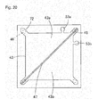
- Fig. 16 is an exploded perspective view of an acoustic sensor 63 according to Embodiment 4 of the present invention.
- Fig. 17 is a plan view showing a state where the canopy section 44 has been removed from the acoustic sensor 63.
- This acoustic sensor 63 is one using a rectangular diaphragm 34.
- the back chamber 45 in columnar form is opened in the silicon substrate 42, and the diaphragm 43 is arranged on the top surface of the silicon substrate 42 so as to cover the upper-surface opening of the back chamber 45.
- Leg sections 72 are provided at four corners of the diaphragm 43, and each of the legs 72 is fixed to the diaphragm 43 by the anchor 46 provided on the top surface of the silicon substrate 42.
- the diaphragm 43 is divided into the diaphragms 43a and 43b by the slit 47 in a diagonal direction.
- the canopy section 44 is also formed in substantially rectangular form so as to cover the rectangular diaphragm 43.
- FIG. 17 represents a displacement amount of the diaphragm 43 during displacement thereof due to acoustic vibrations by means of contours, and the displacement amount is larger at a position closer to the center.
- the center is the maximal displacement place, and forming the slit 47 so as to pass through the maximal displacement place of the diaphragm 43 can increase the S/N ratio improving effect of the acoustic sensor 63.
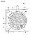
- Fig. 18 is a plan view of an acoustic sensor 64 according to Embodiment 5 of the present invention.
- Fig. 19 is a plan view showing a state where the canopy section 44 has been removed from the acoustic sensor 64.
- the slit 47 is formed from the end to the end of the diaphragm 43 so as to pass through the center of the diaphragm 43. Therefore, in the diaphragm 43, the two diaphragm 43a, 43b are completely separated by the slit 47. Both diaphragms 43a, 43b as thus separated are connected by the leading wire 53 in bifurcated form formed on the top surface of the silicon substrate 42.
- leading wires 53a, 53b may be separately provided in the respective diaphragms 43a, 43b. These leading wires 53a, 53b may be connected to each other outside the acoustic sensor, or connected inside the signal processing circuit (ASIC).
- ASIC signal processing circuit
- the slit 47 in the diaphragm 43, it is preferably provided so as to pass through the maximal displacement place of the diaphragm 43, but the direction of the slit 47 is not particularly restricted.
- the slit 47 has been provided in a direction in which the fixed places of the rectangular diaphragm 43 are connected, namely the diagonal direction of the diaphragm 43, but this is not necessarily restrictive.
- the slit 47 may be formed in a parallel direction to the sides of the rectangular diaphragm 43. In this case, since it is a direction in which the centers of the right and left vent holes 52 are connected to each other, either the divided diaphragm 43a or 43b is supported in cantilever form.
- the slit 47 may be inclined from the diagonal direction of the diaphragm 43 or the direction parallel to the sides thereof.
- the divided diaphragms 43a, 43b are supported in cantilever form when the direction of the slit 47 is not toward the fixed places of the diaphragm 43.
- the diaphragm 43 tends to be broken under the influence of the stress concentration.
- the slit 47 is desirably set in a direction in which the fixed places of the diaphragm 43 are connected as in Embodiment 4.
- Each diaphragm formed on each side of the slit may pass through the slit so as to be connected to each other.
- one slit 47 is partially interrupted and it is as if the two slits 47 are linearly arrayed. Therefore, the diaphragms 43a, 43b located on both sides of the slit 47 with the slit provided therebetween are partially connected to each other through the interrupted portion of the slit 47. There is no problem even with such a form so long as a length of the interrupted portion of the 47 is not excessively large.
- Fig. 24 is a sectional view of a MEMS microphone using an acoustic sensor of each of the above embodiments.
- Fig. 25 is a plan view of the microphone in a state where a cover has been removed.
- This microphone 81 is one housing an acoustic sensor 65 and a signal processing circuit 84 (ASIC) inside a package made up of a circuit substrate 82 and a cover 83.
- the acoustic sensor 65 and the signal processing circuit 84 are mounted on the top surface of the circuit substrate 82. Electrode pads 58, 59 of the acoustic sensor 65 are respectively connected to pads 85a, 85b of the signal processing circuit 84 by bonding wires 91.
- a plurality of terminals 88 for electrically connecting the microphone 81 with the outside are provided on the under surface of the circuit substrate 82, and electrode sections 89a to 89c, 90a, 90b, which are conducted with the terminal 88, are provided on the top surface of the circuit substrate 82.
- Respective pads 86a to 86c, 87a, 87b of the signal processing circuit 84 mounted on the circuit substrate 82 are respectively connected to the electrode sections 89a to 89c, 90a, 90b by bonding wires 92. It is to be noted that the pad of the signal processing circuit 84 has a function of supplying power to the acoustic sensor 65, and a function of outputting a capacity change signal of the acoustic sensor 65 to the outside.
- the cover 83 is attached to the top surface of the circuit substrate 82 so as to cover the acoustic sensor 65 and the signal processing circuit 84.
- a sound introduction port 93 for introducing an acoustic vibration into the package is opened on the top surface of the cover 83.
- the package has a function of an electromagnetic shield, protecting the microphone 81 from electrical disturbance and mechanical shock from the outside.
- an acoustic vibration having entered the package through the sound introduction port 93 is detected by the acoustic sensor 65 and subjected to predetermined signal processing by the signal processing circuit 84, and is then outputted.
- the microphone 81 with a high S/N ratio is formed.
- Fig. 26 shows a microphone 94 with a different structure.
- the sound introduction port 93 is opened not in the cover 83 but in the circuit substrate 82 in a position opposed to the under surface of the hollow section of the silicon substrate 42.
- the hollow section of the silicon substrate 42 serves as a front chamber 95, and the space inside the package serves as the back chamber 45. According to such a form, the volume of the back chamber 45 can be increased, so as to further improve the sensitivity of the microphone 81.
Landscapes
- Physics & Mathematics (AREA)
- Acoustics & Sound (AREA)
- Engineering & Computer Science (AREA)
- Signal Processing (AREA)
- General Physics & Mathematics (AREA)
- Electrostatic, Electromagnetic, Magneto- Strictive, And Variable-Resistance Transducers (AREA)
- Pressure Sensors (AREA)
- Micromachines (AREA)
Applications Claiming Priority (2)
| Application Number | Priority Date | Filing Date | Title |
|---|---|---|---|
| JP2011036903A JP4924853B1 (ja) | 2011-02-23 | 2011-02-23 | 音響センサ及びマイクロフォン |
| PCT/JP2011/056248 WO2012114535A1 (fr) | 2011-02-23 | 2011-03-16 | Capteur acoustique et microphone |
Publications (3)
| Publication Number | Publication Date |
|---|---|
| EP2519030A1 true EP2519030A1 (fr) | 2012-10-31 |
| EP2519030A4 EP2519030A4 (fr) | 2013-05-08 |
| EP2519030B1 EP2519030B1 (fr) | 2014-10-22 |
Family
ID=46243844
Family Applications (1)
| Application Number | Title | Priority Date | Filing Date |
|---|---|---|---|
| EP11770990.7A Not-in-force EP2519030B1 (fr) | 2011-02-23 | 2011-03-16 | Capteur acoustique et microphone |
Country Status (6)
| Country | Link |
|---|---|
| US (1) | US8351625B2 (fr) |
| EP (1) | EP2519030B1 (fr) |
| JP (1) | JP4924853B1 (fr) |
| KR (1) | KR101318332B1 (fr) |
| CN (1) | CN102771143B (fr) |
| WO (1) | WO2012114535A1 (fr) |
Cited By (3)
| Publication number | Priority date | Publication date | Assignee | Title |
|---|---|---|---|---|
| WO2017069701A1 (fr) * | 2015-10-21 | 2017-04-27 | Agency For Science, Technology And Research | Transducteur d'ultrasons et son procédé de fabrication |
| EP3201122A4 (fr) * | 2014-10-02 | 2018-05-30 | Chirp Microsystems Inc. | Transducteurs ultrasoniques micro-usinés ayant une structure de membrane à fentes |
| US20210306728A1 (en) * | 2020-03-27 | 2021-09-30 | Tdk Corporation | Microphone Component and Method for Fabricating Microphone Component |
Families Citing this family (43)
| Publication number | Priority date | Publication date | Assignee | Title |
|---|---|---|---|---|
| US9380380B2 (en) | 2011-01-07 | 2016-06-28 | Stmicroelectronics S.R.L. | Acoustic transducer and interface circuit |
| JP5872163B2 (ja) | 2011-01-07 | 2016-03-01 | オムロン株式会社 | 音響トランスデューサ、および該音響トランスデューサを利用したマイクロフォン |
| US9980052B2 (en) * | 2011-11-14 | 2018-05-22 | Tdk Corporation | MEMS-microphone with reduced parasitic capacitance |
| JP5252104B1 (ja) | 2012-05-31 | 2013-07-31 | オムロン株式会社 | 静電容量型センサ、音響センサ及びマイクロフォン |
| JP5928163B2 (ja) | 2012-05-31 | 2016-06-01 | オムロン株式会社 | 静電容量型センサ、音響センサ及びマイクロフォン |
| JP6028479B2 (ja) * | 2012-09-14 | 2016-11-16 | オムロン株式会社 | 静電容量型センサ、音響センサ及びマイクロフォン |
| GB2506174A (en) * | 2012-09-24 | 2014-03-26 | Wolfson Microelectronics Plc | Protecting a MEMS device from excess pressure and shock |
| US10154330B2 (en) | 2013-07-03 | 2018-12-11 | Harman International Industries, Incorporated | Gradient micro-electro-mechanical systems (MEMS) microphone |
| JP6149628B2 (ja) * | 2013-09-13 | 2017-06-21 | オムロン株式会社 | 音響トランスデューサ及びマイクロフォン |
| JP6179300B2 (ja) * | 2013-09-13 | 2017-08-16 | オムロン株式会社 | 音響トランスデューサ、およびマイクロホン |
| JP6179297B2 (ja) * | 2013-09-13 | 2017-08-16 | オムロン株式会社 | 音響トランスデューサ及びマイクロフォン |
| US9510107B2 (en) * | 2014-03-06 | 2016-11-29 | Infineon Technologies Ag | Double diaphragm MEMS microphone without a backplate element |
| JP6252767B2 (ja) * | 2014-03-14 | 2017-12-27 | オムロン株式会社 | 静電容量型トランスデューサ |
| US20150296305A1 (en) * | 2014-04-10 | 2015-10-15 | Knowles Electronics, Llc | Optimized back plate used in acoustic devices |
| JP6481265B2 (ja) * | 2014-06-18 | 2019-03-13 | 新日本無線株式会社 | Mems素子 |
| US9955246B2 (en) * | 2014-07-03 | 2018-04-24 | Harman International Industries, Incorporated | Gradient micro-electro-mechanical systems (MEMS) microphone with varying height assemblies |
| CN104113812A (zh) * | 2014-08-11 | 2014-10-22 | 苏州敏芯微电子技术有限公司 | 电容式微硅麦克风及其制造方法 |
| JP6467837B2 (ja) * | 2014-09-25 | 2019-02-13 | オムロン株式会社 | 音響トランスデューサ及びマイクロフォン |
| KR101601120B1 (ko) | 2014-10-17 | 2016-03-08 | 현대자동차주식회사 | 마이크로폰 및 그 제조 방법 |
| CN106303868B (zh) * | 2015-06-12 | 2024-01-16 | 钰太芯微电子科技(上海)有限公司 | 一种高信噪比传感器及麦克风 |
| KR101713748B1 (ko) * | 2015-12-09 | 2017-03-08 | 현대자동차주식회사 | 마이크로폰 및 그 제조 방법 |
| US10129651B2 (en) * | 2015-12-18 | 2018-11-13 | Robert Bosch Gmbh | Center-fixed MEMS microphone membrane |
| JP6241982B1 (ja) * | 2016-08-31 | 2017-12-06 | 株式会社トライフォース・マネジメント | 力覚センサ |
| CN107920318B (zh) * | 2016-10-08 | 2020-05-01 | 中芯国际集成电路制造(上海)有限公司 | Mems麦克风及其形成方法 |
| US10798508B2 (en) * | 2016-12-29 | 2020-10-06 | Gmems Tech Shenzhen Limited | Process of fabricating lateral mode capacitive microphone |
| US12075222B2 (en) * | 2016-12-29 | 2024-08-27 | Gmems Tech Shenzhen Limited | Process of fabricating capacitive microphone comprising moveable single conductor and stationary composite conductor |
| US12069455B2 (en) * | 2016-12-29 | 2024-08-20 | Gmems Tech Shenzhen Limited | Process of fabricating lateral mode capacitive microphone including a capacitor plate with sandwich structure |
| US11765534B2 (en) * | 2016-12-29 | 2023-09-19 | Gmems Tech Shenzhen Limited | Capacitive microphone with two signal outputs that are additive inverse of each other |
| US11601763B2 (en) * | 2016-12-29 | 2023-03-07 | Gmems Tech Shenzhen Limited | Lateral mode capacitive microphone including a capacitor plate with sandwich structure for ultra high performance |
| US11765533B2 (en) * | 2016-12-29 | 2023-09-19 | Gmems Tech Shenzhen Limited | Capacitive microphone with two signal outputs that are additive inverse of each other |
| US12075223B2 (en) * | 2016-12-29 | 2024-08-27 | Gmems Tech Shenzhen Limited | Process of fabricating capacitive microphone comprising movable composite conductor and stationary single conductor |
| JP6745774B2 (ja) | 2017-09-20 | 2020-08-26 | 株式会社東芝 | センサ及び電子機器 |
| CN109534277B (zh) * | 2017-09-22 | 2021-05-04 | 中芯国际集成电路制造(上海)有限公司 | Mems麦克风及其形成方法 |
| KR102499855B1 (ko) * | 2018-05-03 | 2023-02-13 | 주식회사 디비하이텍 | 멤스 마이크로폰 이를 포함하는 멤스 마이크로폰 패키지 및 이의 제조 방법 |
| KR102486584B1 (ko) * | 2018-05-03 | 2023-01-10 | 주식회사 디비하이텍 | 멤스 마이크로폰, 이를 포함하는 멤스 마이크로폰 패키지 및 이의 제조 방법 |
| JP7147335B2 (ja) * | 2018-07-31 | 2022-10-05 | Tdk株式会社 | Memsマイクロフォン |
| CN109660927B (zh) * | 2018-12-29 | 2024-04-12 | 华景科技无锡有限公司 | 一种麦克风芯片及麦克风 |
| TWI770543B (zh) * | 2020-06-29 | 2022-07-11 | 美律實業股份有限公司 | 麥克風結構 |
| CN111711901B (zh) * | 2020-08-19 | 2020-12-22 | 共达电声股份有限公司 | Mems传感器芯片 |
| CN113132876B (zh) * | 2021-03-01 | 2023-08-04 | 歌尔微电子股份有限公司 | 微机电麦克风及电子设备 |
| US12287280B2 (en) * | 2022-08-17 | 2025-04-29 | Invensense, Inc. | Photoacoustic gas sensors with improved signal-to-noise ratio |
| CN115914962B (zh) * | 2023-01-05 | 2023-05-30 | 苏州敏芯微电子技术股份有限公司 | 麦克风组件、制备方法及电子设备 |
| CN118566532B (zh) * | 2024-07-04 | 2025-01-28 | 深圳市晶扬电子有限公司 | 气流传感器以及气流传感器封装结构 |
Family Cites Families (11)
| Publication number | Priority date | Publication date | Assignee | Title |
|---|---|---|---|---|
| JPS62213400A (ja) * | 1986-03-13 | 1987-09-19 | Sony Corp | コンデンサ形マイクロホン |
| JPH0726887B2 (ja) * | 1986-05-31 | 1995-03-29 | 株式会社堀場製作所 | コンデンサマイクロフオン型検出器用ダイアフラム |
| JP4101785B2 (ja) * | 2003-09-11 | 2008-06-18 | アオイ電子株式会社 | コンデンサーマイクロフォン及びその作製方法 |
| WO2007024909A1 (fr) * | 2005-08-23 | 2007-03-01 | Analog Devices, Inc. | Systeme multi-microphones |
| GB0605576D0 (en) * | 2006-03-20 | 2006-04-26 | Oligon Ltd | MEMS device |
| JP4770605B2 (ja) | 2006-06-26 | 2011-09-14 | ヤマハ株式会社 | 平衡出力マイクロホンおよび平衡出力マイクロホンの製造方法 |
| CN101346014B (zh) * | 2007-07-13 | 2012-06-20 | 清华大学 | 微机电系统麦克风及其制备方法 |
| JP2009124474A (ja) * | 2007-11-15 | 2009-06-04 | Yamaha Corp | 静電型スピーカ |
| KR101113366B1 (ko) * | 2008-02-20 | 2012-03-02 | 오므론 가부시키가이샤 | 정전 용량형 진동 센서 |
| JP4419103B1 (ja) * | 2008-08-27 | 2010-02-24 | オムロン株式会社 | 静電容量型振動センサ |
| IT1395550B1 (it) * | 2008-12-23 | 2012-09-28 | St Microelectronics Rousset | Trasduttore acustico integrato in tecnologia mems e relativo processo di fabbricazione |
-
2011
- 2011-02-23 JP JP2011036903A patent/JP4924853B1/ja not_active Expired - Fee Related
- 2011-03-16 EP EP11770990.7A patent/EP2519030B1/fr not_active Not-in-force
- 2011-03-16 CN CN201180001987.3A patent/CN102771143B/zh not_active Expired - Fee Related
- 2011-03-16 KR KR1020117025833A patent/KR101318332B1/ko active Active
- 2011-03-16 WO PCT/JP2011/056248 patent/WO2012114535A1/fr not_active Ceased
- 2011-03-16 US US13/318,261 patent/US8351625B2/en active Active
Cited By (7)
| Publication number | Priority date | Publication date | Assignee | Title |
|---|---|---|---|---|
| EP3201122A4 (fr) * | 2014-10-02 | 2018-05-30 | Chirp Microsystems Inc. | Transducteurs ultrasoniques micro-usinés ayant une structure de membrane à fentes |
| US10293377B2 (en) | 2014-10-02 | 2019-05-21 | Chirp Microsystems | Micromachined ultrasonic transducers with a slotted membrane structure |
| WO2017069701A1 (fr) * | 2015-10-21 | 2017-04-27 | Agency For Science, Technology And Research | Transducteur d'ultrasons et son procédé de fabrication |
| US11229927B2 (en) | 2015-10-21 | 2022-01-25 | Agency For Science, Technology And Research | Ultrasound transducer and method of forming ihe same |
| US20210306728A1 (en) * | 2020-03-27 | 2021-09-30 | Tdk Corporation | Microphone Component and Method for Fabricating Microphone Component |
| US11736845B2 (en) * | 2020-03-27 | 2023-08-22 | Tdk Corporation | Microphone component and method for fabricating microphone component |
| US12096170B2 (en) | 2020-03-27 | 2024-09-17 | Tdk Corporation | Microphone component and method for fabricating microphone component |
Also Published As
| Publication number | Publication date |
|---|---|
| US8351625B2 (en) | 2013-01-08 |
| US20120213400A1 (en) | 2012-08-23 |
| JP4924853B1 (ja) | 2012-04-25 |
| EP2519030B1 (fr) | 2014-10-22 |
| CN102771143A (zh) | 2012-11-07 |
| KR20120128538A (ko) | 2012-11-27 |
| CN102771143B (zh) | 2015-04-22 |
| EP2519030A4 (fr) | 2013-05-08 |
| KR101318332B1 (ko) | 2013-10-16 |
| JP2012175508A (ja) | 2012-09-10 |
| WO2012114535A1 (fr) | 2012-08-30 |
Similar Documents
| Publication | Publication Date | Title |
|---|---|---|
| EP2519030B1 (fr) | Capteur acoustique et microphone | |
| EP2605545A1 (fr) | Capteur acoustique et microphone | |
| TWI622552B (zh) | 微機電系統設備與製程 | |
| CN104469640B (zh) | 声响转换器及麦克风 | |
| CN107404697B (zh) | 具有梳齿式电极的mems声换能器及对应的制造方法 | |
| CN104469578B (zh) | 声响转换器及麦克风 | |
| US20160037266A1 (en) | Capacitance type sensor, acoustic sensor, and microphone | |
| JP6028479B2 (ja) | 静電容量型センサ、音響センサ及びマイクロフォン | |
| JP5928163B2 (ja) | 静電容量型センサ、音響センサ及びマイクロフォン | |
| WO2016120213A1 (fr) | Dispositifs et procédés mems | |
| EP3334184B1 (fr) | Capteur acoustique et transducteur capacitif | |
| US20150078589A1 (en) | Capacitance-type transducer, acoustic sensor, and microphone | |
| CN105144750A (zh) | 声音变换器 | |
| KR101514567B1 (ko) | 음향 소자 및 이를 구비하는 마이크로폰 패키지 | |
| US20250100871A1 (en) | Electrodes for microelectromechanical system microphones | |
| US20250206600A1 (en) | Acoustic sensor devices with multiple sensing elements |
Legal Events
| Date | Code | Title | Description |
|---|---|---|---|
| PUAI | Public reference made under article 153(3) epc to a published international application that has entered the european phase |
Free format text: ORIGINAL CODE: 0009012 |
|
| 17P | Request for examination filed |
Effective date: 20120118 |
|
| AK | Designated contracting states |
Kind code of ref document: A1 Designated state(s): AL AT BE BG CH CY CZ DE DK EE ES FI FR GB GR HR HU IE IS IT LI LT LU LV MC MK MT NL NO PL PT RO RS SE SI SK SM TR |
|
| A4 | Supplementary search report drawn up and despatched |
Effective date: 20130409 |
|
| RIC1 | Information provided on ipc code assigned before grant |
Ipc: H04R 19/00 20060101ALI20130403BHEP Ipc: H04R 19/04 20060101AFI20130403BHEP |
|
| RIN1 | Information on inventor provided before grant (corrected) |
Inventor name: KASAI, TAKASHI |
|
| GRAP | Despatch of communication of intention to grant a patent |
Free format text: ORIGINAL CODE: EPIDOSNIGR1 |
|
| DAX | Request for extension of the european patent (deleted) | ||
| INTG | Intention to grant announced |
Effective date: 20140416 |
|
| GRAS | Grant fee paid |
Free format text: ORIGINAL CODE: EPIDOSNIGR3 |
|
| RAP1 | Party data changed (applicant data changed or rights of an application transferred) |
Owner name: OMRON CORPORATION |
|
| GRAA | (expected) grant |
Free format text: ORIGINAL CODE: 0009210 |
|
| AK | Designated contracting states |
Kind code of ref document: B1 Designated state(s): AL AT BE BG CH CY CZ DE DK EE ES FI FR GB GR HR HU IE IS IT LI LT LU LV MC MK MT NL NO PL PT RO RS SE SI SK SM TR |
|
| REG | Reference to a national code |
Ref country code: GB Ref legal event code: FG4D |
|
| REG | Reference to a national code |
Ref country code: CH Ref legal event code: EP |
|
| REG | Reference to a national code |
Ref country code: AT Ref legal event code: REF Ref document number: 693076 Country of ref document: AT Kind code of ref document: T Effective date: 20141115 |
|
| REG | Reference to a national code |
Ref country code: IE Ref legal event code: FG4D |
|
| REG | Reference to a national code |
Ref country code: DE Ref legal event code: R096 Ref document number: 602011010819 Country of ref document: DE Effective date: 20141204 |
|
| REG | Reference to a national code |
Ref country code: NL Ref legal event code: VDEP Effective date: 20141022 |
|
| REG | Reference to a national code |
Ref country code: AT Ref legal event code: MK05 Ref document number: 693076 Country of ref document: AT Kind code of ref document: T Effective date: 20141022 |
|
| REG | Reference to a national code |
Ref country code: LT Ref legal event code: MG4D |
|
| PG25 | Lapsed in a contracting state [announced via postgrant information from national office to epo] |
Ref country code: NO Free format text: LAPSE BECAUSE OF FAILURE TO SUBMIT A TRANSLATION OF THE DESCRIPTION OR TO PAY THE FEE WITHIN THE PRESCRIBED TIME-LIMIT Effective date: 20150122 Ref country code: PT Free format text: LAPSE BECAUSE OF FAILURE TO SUBMIT A TRANSLATION OF THE DESCRIPTION OR TO PAY THE FEE WITHIN THE PRESCRIBED TIME-LIMIT Effective date: 20150223 Ref country code: FI Free format text: LAPSE BECAUSE OF FAILURE TO SUBMIT A TRANSLATION OF THE DESCRIPTION OR TO PAY THE FEE WITHIN THE PRESCRIBED TIME-LIMIT Effective date: 20141022 Ref country code: LT Free format text: LAPSE BECAUSE OF FAILURE TO SUBMIT A TRANSLATION OF THE DESCRIPTION OR TO PAY THE FEE WITHIN THE PRESCRIBED TIME-LIMIT Effective date: 20141022 Ref country code: ES Free format text: LAPSE BECAUSE OF FAILURE TO SUBMIT A TRANSLATION OF THE DESCRIPTION OR TO PAY THE FEE WITHIN THE PRESCRIBED TIME-LIMIT Effective date: 20141022 Ref country code: NL Free format text: LAPSE BECAUSE OF FAILURE TO SUBMIT A TRANSLATION OF THE DESCRIPTION OR TO PAY THE FEE WITHIN THE PRESCRIBED TIME-LIMIT Effective date: 20141022 Ref country code: IS Free format text: LAPSE BECAUSE OF FAILURE TO SUBMIT A TRANSLATION OF THE DESCRIPTION OR TO PAY THE FEE WITHIN THE PRESCRIBED TIME-LIMIT Effective date: 20150222 |
|
| PG25 | Lapsed in a contracting state [announced via postgrant information from national office to epo] |
Ref country code: GR Free format text: LAPSE BECAUSE OF FAILURE TO SUBMIT A TRANSLATION OF THE DESCRIPTION OR TO PAY THE FEE WITHIN THE PRESCRIBED TIME-LIMIT Effective date: 20150123 Ref country code: AT Free format text: LAPSE BECAUSE OF FAILURE TO SUBMIT A TRANSLATION OF THE DESCRIPTION OR TO PAY THE FEE WITHIN THE PRESCRIBED TIME-LIMIT Effective date: 20141022 Ref country code: RS Free format text: LAPSE BECAUSE OF FAILURE TO SUBMIT A TRANSLATION OF THE DESCRIPTION OR TO PAY THE FEE WITHIN THE PRESCRIBED TIME-LIMIT Effective date: 20141022 Ref country code: SE Free format text: LAPSE BECAUSE OF FAILURE TO SUBMIT A TRANSLATION OF THE DESCRIPTION OR TO PAY THE FEE WITHIN THE PRESCRIBED TIME-LIMIT Effective date: 20141022 Ref country code: HR Free format text: LAPSE BECAUSE OF FAILURE TO SUBMIT A TRANSLATION OF THE DESCRIPTION OR TO PAY THE FEE WITHIN THE PRESCRIBED TIME-LIMIT Effective date: 20141022 Ref country code: CY Free format text: LAPSE BECAUSE OF FAILURE TO SUBMIT A TRANSLATION OF THE DESCRIPTION OR TO PAY THE FEE WITHIN THE PRESCRIBED TIME-LIMIT Effective date: 20141022 Ref country code: LV Free format text: LAPSE BECAUSE OF FAILURE TO SUBMIT A TRANSLATION OF THE DESCRIPTION OR TO PAY THE FEE WITHIN THE PRESCRIBED TIME-LIMIT Effective date: 20141022 Ref country code: PL Free format text: LAPSE BECAUSE OF FAILURE TO SUBMIT A TRANSLATION OF THE DESCRIPTION OR TO PAY THE FEE WITHIN THE PRESCRIBED TIME-LIMIT Effective date: 20141022 |
|
| REG | Reference to a national code |
Ref country code: DE Ref legal event code: R097 Ref document number: 602011010819 Country of ref document: DE |
|
| PG25 | Lapsed in a contracting state [announced via postgrant information from national office to epo] |
Ref country code: CZ Free format text: LAPSE BECAUSE OF FAILURE TO SUBMIT A TRANSLATION OF THE DESCRIPTION OR TO PAY THE FEE WITHIN THE PRESCRIBED TIME-LIMIT Effective date: 20141022 Ref country code: RO Free format text: LAPSE BECAUSE OF FAILURE TO SUBMIT A TRANSLATION OF THE DESCRIPTION OR TO PAY THE FEE WITHIN THE PRESCRIBED TIME-LIMIT Effective date: 20141022 Ref country code: SK Free format text: LAPSE BECAUSE OF FAILURE TO SUBMIT A TRANSLATION OF THE DESCRIPTION OR TO PAY THE FEE WITHIN THE PRESCRIBED TIME-LIMIT Effective date: 20141022 Ref country code: EE Free format text: LAPSE BECAUSE OF FAILURE TO SUBMIT A TRANSLATION OF THE DESCRIPTION OR TO PAY THE FEE WITHIN THE PRESCRIBED TIME-LIMIT Effective date: 20141022 Ref country code: DK Free format text: LAPSE BECAUSE OF FAILURE TO SUBMIT A TRANSLATION OF THE DESCRIPTION OR TO PAY THE FEE WITHIN THE PRESCRIBED TIME-LIMIT Effective date: 20141022 |
|
| PLBE | No opposition filed within time limit |
Free format text: ORIGINAL CODE: 0009261 |
|
| STAA | Information on the status of an ep patent application or granted ep patent |
Free format text: STATUS: NO OPPOSITION FILED WITHIN TIME LIMIT |
|
| PG25 | Lapsed in a contracting state [announced via postgrant information from national office to epo] |
Ref country code: IT Free format text: LAPSE BECAUSE OF FAILURE TO SUBMIT A TRANSLATION OF THE DESCRIPTION OR TO PAY THE FEE WITHIN THE PRESCRIBED TIME-LIMIT Effective date: 20141022 |
|
| 26N | No opposition filed |
Effective date: 20150723 |
|
| PG25 | Lapsed in a contracting state [announced via postgrant information from national office to epo] |
Ref country code: MC Free format text: LAPSE BECAUSE OF FAILURE TO SUBMIT A TRANSLATION OF THE DESCRIPTION OR TO PAY THE FEE WITHIN THE PRESCRIBED TIME-LIMIT Effective date: 20141022 Ref country code: LU Free format text: LAPSE BECAUSE OF FAILURE TO SUBMIT A TRANSLATION OF THE DESCRIPTION OR TO PAY THE FEE WITHIN THE PRESCRIBED TIME-LIMIT Effective date: 20150316 |
|
| REG | Reference to a national code |
Ref country code: CH Ref legal event code: PL |
|
| GBPC | Gb: european patent ceased through non-payment of renewal fee |
Effective date: 20150316 |
|
| REG | Reference to a national code |
Ref country code: FR Ref legal event code: ST Effective date: 20151130 |
|
| REG | Reference to a national code |
Ref country code: IE Ref legal event code: MM4A |
|
| PG25 | Lapsed in a contracting state [announced via postgrant information from national office to epo] |
Ref country code: GB Free format text: LAPSE BECAUSE OF NON-PAYMENT OF DUE FEES Effective date: 20150316 Ref country code: IE Free format text: LAPSE BECAUSE OF NON-PAYMENT OF DUE FEES Effective date: 20150316 Ref country code: CH Free format text: LAPSE BECAUSE OF NON-PAYMENT OF DUE FEES Effective date: 20150331 Ref country code: LI Free format text: LAPSE BECAUSE OF NON-PAYMENT OF DUE FEES Effective date: 20150331 |
|
| PG25 | Lapsed in a contracting state [announced via postgrant information from national office to epo] |
Ref country code: FR Free format text: LAPSE BECAUSE OF NON-PAYMENT OF DUE FEES Effective date: 20150331 Ref country code: SI Free format text: LAPSE BECAUSE OF FAILURE TO SUBMIT A TRANSLATION OF THE DESCRIPTION OR TO PAY THE FEE WITHIN THE PRESCRIBED TIME-LIMIT Effective date: 20141022 |
|
| PG25 | Lapsed in a contracting state [announced via postgrant information from national office to epo] |
Ref country code: MT Free format text: LAPSE BECAUSE OF FAILURE TO SUBMIT A TRANSLATION OF THE DESCRIPTION OR TO PAY THE FEE WITHIN THE PRESCRIBED TIME-LIMIT Effective date: 20141022 |
|
| PG25 | Lapsed in a contracting state [announced via postgrant information from national office to epo] |
Ref country code: HU Free format text: LAPSE BECAUSE OF FAILURE TO SUBMIT A TRANSLATION OF THE DESCRIPTION OR TO PAY THE FEE WITHIN THE PRESCRIBED TIME-LIMIT; INVALID AB INITIO Effective date: 20110316 Ref country code: BG Free format text: LAPSE BECAUSE OF FAILURE TO SUBMIT A TRANSLATION OF THE DESCRIPTION OR TO PAY THE FEE WITHIN THE PRESCRIBED TIME-LIMIT Effective date: 20141022 Ref country code: SM Free format text: LAPSE BECAUSE OF FAILURE TO SUBMIT A TRANSLATION OF THE DESCRIPTION OR TO PAY THE FEE WITHIN THE PRESCRIBED TIME-LIMIT Effective date: 20141022 |
|
| PG25 | Lapsed in a contracting state [announced via postgrant information from national office to epo] |
Ref country code: TR Free format text: LAPSE BECAUSE OF FAILURE TO SUBMIT A TRANSLATION OF THE DESCRIPTION OR TO PAY THE FEE WITHIN THE PRESCRIBED TIME-LIMIT Effective date: 20141022 |
|
| PG25 | Lapsed in a contracting state [announced via postgrant information from national office to epo] |
Ref country code: BE Free format text: LAPSE BECAUSE OF FAILURE TO SUBMIT A TRANSLATION OF THE DESCRIPTION OR TO PAY THE FEE WITHIN THE PRESCRIBED TIME-LIMIT Effective date: 20141022 |
|
| PG25 | Lapsed in a contracting state [announced via postgrant information from national office to epo] |
Ref country code: MK Free format text: LAPSE BECAUSE OF FAILURE TO SUBMIT A TRANSLATION OF THE DESCRIPTION OR TO PAY THE FEE WITHIN THE PRESCRIBED TIME-LIMIT Effective date: 20141022 |
|
| PG25 | Lapsed in a contracting state [announced via postgrant information from national office to epo] |
Ref country code: AL Free format text: LAPSE BECAUSE OF FAILURE TO SUBMIT A TRANSLATION OF THE DESCRIPTION OR TO PAY THE FEE WITHIN THE PRESCRIBED TIME-LIMIT Effective date: 20141022 |
|
| REG | Reference to a national code |
Ref country code: DE Ref legal event code: R081 Ref document number: 602011010819 Country of ref document: DE Owner name: MMI SEMICONDUCTOR CO., LTD., TAMA-SHI, JP Free format text: FORMER OWNER: OMRON CORP., KYOTO-SHI, JP |
|
| PGFP | Annual fee paid to national office [announced via postgrant information from national office to epo] |
Ref country code: DE Payment date: 20240130 Year of fee payment: 14 |
|
| REG | Reference to a national code |
Ref country code: DE Ref legal event code: R119 Ref document number: 602011010819 Country of ref document: DE |
|
| PG25 | Lapsed in a contracting state [announced via postgrant information from national office to epo] |
Ref country code: DE Free format text: LAPSE BECAUSE OF NON-PAYMENT OF DUE FEES Effective date: 20251001 |